Journal of Physics: Conference Series OPEN ACCESS Characterization of polarization sensitive, high efficiency dielectric gratings for formation flight interferometry To cite this article: Ke-Xun Sun et al 2009 J. Phys.: Conf. Ser. 154 012031 View the article online for updates and enhancements. You may also like Electromagnetic interaction of atoms with an evanescent light field in attenuated total reflection spectroscopy Kazuyuki Muroo - Efficient transient photocurrent generation in waveguide-type bacteriorhodopsin photocells Toshiki Yamada, Katsuyuki Kasai, Takahiro Kaji et al. - Tunable enhancement of spatial lateral shifts in periodic chiral metamaterials Yanyan Huang, Qingqing Zhu, Xiaowei Zhang et al. - Recent citations Deep-etched sinusoidal polarizing beam splitter grating Jijun Feng et al - Precise diffraction efficiency measurements of large-area greater-than- 99%-efficient dielectric gratings at the Littrow angle Patrick P. Lu et al - This content was downloaded from IP address 185.122.173.101 on 02/12/2021 at 18:23
Transcript
Journal of Physics Conference Series
OPEN ACCESS
Characterization of polarization sensitive highefficiency dielectric gratings for formation flightinterferometryTo cite this article Ke-Xun Sun et al 2009 J Phys Conf Ser 154 012031
View the article online for updates and enhancements
You may also likeElectromagnetic interaction of atoms withan evanescent light field in attenuated totalreflection spectroscopyKazuyuki Muroo
-
Efficient transient photocurrent generationin waveguide-type bacteriorhodopsinphotocellsToshiki Yamada Katsuyuki KasaiTakahiro Kaji et al
-
Tunable enhancement of spatial lateralshifts in periodic chiral metamaterialsYanyan Huang Qingqing Zhu XiaoweiZhang et al
-
Recent citationsDeep-etched sinusoidal polarizing beamsplitter gratingJijun Feng et al
-
Precise diffraction efficiencymeasurements of large-area greater-than-99-efficient dielectric gratings at theLittrow anglePatrick P Lu et al
-
This content was downloaded from IP address 185122173101 on 02122021 at 1823
Characterization of Polarization Sensitive High Efficiency Dielectric Gratings for Formation Flight Interferometry
Ke-Xun Sun Patrick Lu and Robert L Byer
Ginzton Laboratory N-119 Stanford University Stanford CA94305-4088 USA
Jerald A Britten Hoang T Nguyen James D Nissen Cindy C Larson Michael D Aasen Thomas C Carlson and Curly R Hoaglan
Lawrence Livermore National Laboratory Livermore CA 94550 USA
kxsunstanfordedu
Abstract Reflective diffraction gratings enable novel optical configurations that simplify and improve laser interferometers We have proposed an all-reflective grating interferometer that can be used in LISA type interferometers for space gravitational wave detection [1] One configuration requires a highly polarization sensitive grating We report on characterizations of a grating made atop high reflective dielectric layers Using a direct measurement method the diffraction efficiency at the Littrow angle for s-polarization is measured as 973 and for p-polarization 42 leading to a sp polarization diffraction ratio of 232 The depolarization from s- to p-polarization is measured to be ~17times10-4 and from p- to s-polarization 18times10-4 We derived a transfer matrix based on these measurements Furthermore we have developed a more accurate method for diffraction efficiency measurement using a grating cavity These measurements are encouraging steps taken towards the requirements of an ideal grating interferometer
1 Introduction
Grating interferometers have been proposed for ground-based gravitational wave detectors such as Laser Interferometer Gravitational Observatory (LIGO) [1] Grating interferometers may also benefit Laser Interferometer Space Antenna (LISA) by both simplifying optical configurations and enhancing instrument performance [2]
LISA [3] and other formation flights for fundamental physics must make connected distance measurements from the gravitational reference sensor (GRS) center to the GRS housing and to other spacecrafts In the Modular GRS (MGRS) design [2] we proposed using a double-sided reflective grating at the connecting points so that both the GRS internal interferometry and external inter-spacecraft interferometry can be independently optimized For the external interferometry a highly polarization-sensitive high-efficiency grating will be needed Ideally the diffraction efficiency should be near unity in the high efficiency polarization but near zero in the low efficiency polarization In addition the depolarization or the cross coupling of the two polarizations should be as low as possible
7th International LISA Symposium IOP PublishingJournal of Physics Conference Series 154 (2009) 012031 doi1010881742-65961541012031
ccopy 2009 IOP Publishing Ltd 1
Such a grating can be difficult to find if we are limited to conventional metal gratings However the exciting development of multilayer dielectric (MLD) gratings provides a promising solution [4] In this paper we report on characterizations of two high-efficiency dielectric gratings designed and fabricated at Lawrence Livermore National Laboratory Using a direct measurement method the diffraction efficiency of one grating at the Littrow angle for s-polarization is measured to be 973 and for p-polarization 42 leading to a sp polarization diffraction ratio of 232 The depolarization from s- to p- was measured to be ~17times10-4 and from p- to s- 18times10-4 Further improvement of the grating characteristics are needed However these characteristics are already very promising for an initial build of the grating interferometer described in [2]
We further report measurement results using a grating cavity for a more accurate determination of diffraction efficiency and thermal wavefront distortion measurements made to characterize grating power handling
2 Reflective Interferometry Using a Polarization Sensitive Grating
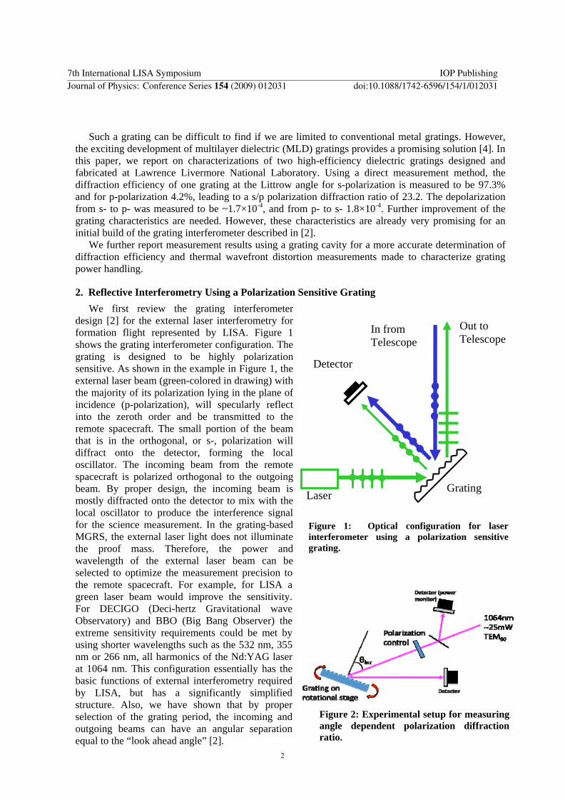
We first review the grating interferometer design [2] for the external laser interferometry for formation flight represented by LISA Figure 1 shows the grating interferometer configuration The grating is designed to be highly polarization sensitive As shown in the example in Figure 1 the external laser beam (green-colored in drawing) with the majority of its polarization lying in the plane of incidence (p-polarization) will specularly reflect into the zeroth order and be transmitted to the remote spacecraft The small portion of the beam that is in the orthogonal or s- polarization will diffract onto the detector forming the local oscillator The incoming beam from the remote spacecraft is polarized orthogonal to the outgoing beam By proper design the incoming beam is mostly diffracted onto the detector to mix with the local oscillator to produce the interference signal for the science measurement In the grating-based MGRS the external laser light does not illuminate the proof mass Therefore the power and wavelength of the external laser beam can be selected to optimize the measurement precision to the remote spacecraft For example for LISA a green laser beam would improve the sensitivity For DECIGO (Deci-hertz Gravitational wave Observatory) and BBO (Big Bang Observer) the extreme sensitivity requirements could be met by using shorter wavelengths such as the 532 nm 355 nm or 266 nm all harmonics of the NdYAG laser at 1064 nm This configuration essentially has the basic functions of external interferometry required by LISA but has a significantly simplified structure Also we have shown that by proper selection of the grating period the incoming and outgoing beams can have an angular separation equal to the ldquolook ahead anglerdquo [2]
Figure 1 Optical configuration for laser interferometer using a polarization sensitive grating
Out to Telescope
In from Telescope
Detector
Laser Grating
Figure 2 Experimental setup for measuring angle dependent polarization diffraction ratio
7th International LISA Symposium IOP PublishingJournal of Physics Conference Series 154 (2009) 012031 doi1010881742-65961541012031
2
3 Incident angle dependence of diffraction efficiency for each polarization
The design of a grating enjoys freedom to achieve the desired diffraction characteristics The diffraction angles are determined by the grating period The diffraction efficiency depends on the details of the grating shape depth and design of the underlying stack [5] as does the polarization selectivity The verification of strong polarization dependence of diffraction efficiency is a first step towards the polarization grating interferometer proposed in [2] If verified we can adjust the grating period and other parameters to tune the grating diffraction angle according to the requirement of the interferometer
Our first measurements were therefore made to confirm the feasibility of using a grating to separate s- and p-polarized light An all-dielectric diffraction grating consisting of a SiO2HfO2 multilayer stack coated on a 100 mm diameter BK7 substrate at the University of Rochester Laboratory for Laser Energetics with a 1740 linemm grating patterned and etched into the top 575 nm-thick SiO2 capping layer at LLNL was used for this experiment
The experimental setup is illustrated in Figure 2 A monochromatic 1064 nm 25 mW laser beam from an NPRO laser was directed through a mode cleaner and a half-wave plate The latter allowed for polarization rotation This laser beam was directed at the grating mounted on a rotational stage A detector was placed so that it captured light diffracting off the grating Measurements were taken for a range of incident angles and results are plotted in Figure 3
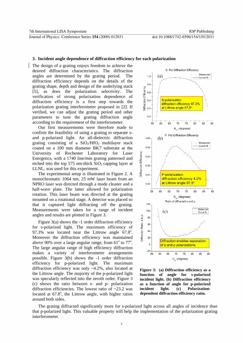
Figure 3(a) shows the -1 order diffraction efficiency for s-polarized light The maximum efficiency of 973 was located near the Littrow angle 678o Moreover the diffraction efficiency was maintained above 90 over a large angular range from 61o to 77o The large angular range of high efficiency diffraction makes a variety of interferometer arrangements possible Figure 3(b) shows the -1 order diffraction efficiency for p-polarized light The maximum diffraction efficiency was only ~42 also located at the Littrow angle The majority of the p-polarized light was specularly reflected into the zeroth order Figure 3 (c) shows the ratio between s- and p- polarization diffraction efficiencies The lowest ratio of ~232 was located at 678o the Littrow angle with higher ratios around both sides
The grating diffracted significantly more for s-polarized light across all angles of incidence than that p-polarized light This valuable property will help the implementation of the polarization grating interferometer
(a)
(b)
Figure 3 (a) Diffraction efficiency as a function of angle for s-polarized incident light (b) Diffraction efficiency as a function of angle for p-polarized incident light (c) Polarization-dependent diffraction efficiency ratio
(c)
7th International LISA Symposium IOP PublishingJournal of Physics Conference Series 154 (2009) 012031 doi1010881742-65961541012031
3
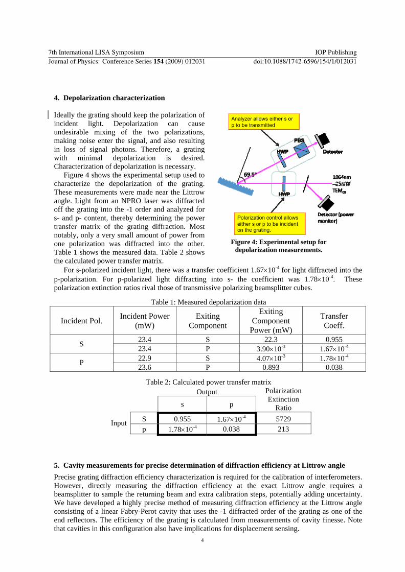
4 Depolarization characterization Ideally the grating should keep the polarization of incident light Depolarization can cause undesirable mixing of the two polarizations making noise enter the signal and also resulting in loss of signal photons Therefore a grating with minimal depolarization is desired Characterization of depolarization is necessary
Figure 4 shows the experimental setup used to characterize the depolarization of the grating These measurements were made near the Littrow angle Light from an NPRO laser was diffracted off the grating into the -1 order and analyzed for s- and p- content thereby determining the power transfer matrix of the grating diffraction Most notably only a very small amount of power from one polarization was diffracted into the other Table 1 shows the measured data Table 2 shows the calculated power transfer matrix
For s-polarized incident light there was a transfer coefficient 167times10-4 for light diffracted into the p-polarization For p-polarized light diffracting into s- the coefficient was 178times10-4 These polarization extinction ratios rival those of transmissive polarizing beamsplitter cubes
Table 1 Measured depolarization data
Incident Pol Incident Power (mW)
Exiting Component
Exiting Component
Power (mW)
Transfer Coeff
234 S 223 0955 S 234 P 390times10-3 167times10-4 229 S 407times10-3 178times10-4 P 236 P 0893 0038
Table 2 Calculated power transfer matrix Output s p
Polarization Extinction
Ratio S 0955 167times10-4 5729 Input p 178times10-4 0038 213
5 Cavity measurements for precise determination of diffraction efficiency at Littrow angle
Precise grating diffraction efficiency characterization is required for the calibration of interferometers However directly measuring the diffraction efficiency at the exact Littrow angle requires a beamsplitter to sample the returning beam and extra calibration steps potentially adding uncertainty We have developed a highly precise method of measuring diffraction efficiency at the Littrow angle consisting of a linear Fabry-Perot cavity that uses the -1 diffracted order of the grating as one of the end reflectors The efficiency of the grating is calculated from measurements of cavity finesse Note that cavities in this configuration also have implications for displacement sensing
Figure 4 Experimental setup for depolarization measurements
7th International LISA Symposium IOP PublishingJournal of Physics Conference Series 154 (2009) 012031 doi1010881742-65961541012031
4
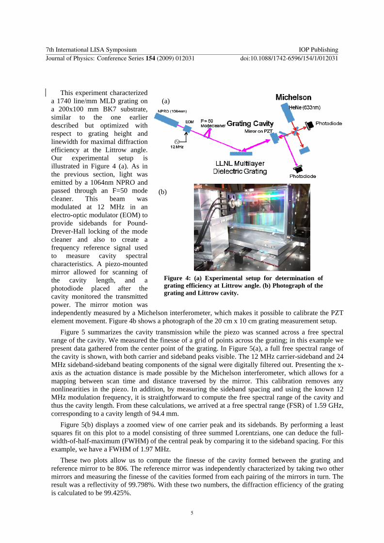
This experiment characterized a 1740 linemm MLD grating on a 200x100 mm BK7 substrate similar to the one earlier described but optimized with respect to grating height and linewidth for maximal diffraction efficiency at the Littrow angle Our experimental setup is illustrated in Figure 4 (a) As in the previous section light was emitted by a 1064nm NPRO and passed through an F=50 mode cleaner This beam was modulated at 12 MHz in an electro-optic modulator (EOM) to provide sidebands for Pound-Drever-Hall locking of the mode cleaner and also to create a frequency reference signal used to measure cavity spectral characteristics A piezo-mounted mirror allowed for scanning of the cavity length and a photodiode placed after the cavity monitored the transmitted power The mirror motion was independently measured by a Michelson interferometer which makes it possible to calibrate the PZT element movement Figure 4b shows a photograph of the 20 cm x 10 cm grating measurement setup
Figure 5 summarizes the cavity transmission while the piezo was scanned across a free spectral range of the cavity We measured the finesse of a grid of points across the grating in this example we present data gathered from the center point of the grating In Figure 5(a) a full free spectral range of the cavity is shown with both carrier and sideband peaks visible The 12 MHz carrier-sideband and 24 MHz sideband-sideband beating components of the signal were digitally filtered out Presenting the x-axis as the actuation distance is made possible by the Michelson interferometer which allows for a mapping between scan time and distance traversed by the mirror This calibration removes any nonlinearities in the piezo In addition by measuring the sideband spacing and using the known 12 MHz modulation frequency it is straightforward to compute the free spectral range of the cavity and thus the cavity length From these calculations we arrived at a free spectral range (FSR) of 159 GHz corresponding to a cavity length of 944 mm
Figure 5(b) displays a zoomed view of one carrier peak and its sidebands By performing a least squares fit on this plot to a model consisting of three summed Lorentzians one can deduce the full-width-of-half-maximum (FWHM) of the central peak by comparing it to the sideband spacing For this example we have a FWHM of 197 MHz
These two plots allow us to compute the finesse of the cavity formed between the grating and reference mirror to be 806 The reference mirror was independently characterized by taking two other mirrors and measuring the finesse of the cavities formed from each pairing of the mirrors in turn The result was a reflectivity of 99798 With these two numbers the diffraction efficiency of the grating is calculated to be 99425
(a)
Figure 4 (a) Experimental setup for determination of grating efficiency at Littrow angle (b) Photograph of the grating and Littrow cavity
(b)
7th International LISA Symposium IOP PublishingJournal of Physics Conference Series 154 (2009) 012031 doi1010881742-65961541012031
5
6 Grating power handling capability
As a test of the power handling capabilities of the dielectric grating we illuminated a 1 mm patch of grating with 34W of 1064 nm light from a master oscillator power amplifier system The illuminated spot was monitored with a Shack-Hartmann wavefront sensor confirming that no significant wavefront distortions were present [6] The power levels tested were significantly greater than the 2W required by LISA indicating that similar gratings will be good candidates for BBO and DECIGO which require ~100W of laser power
7 Summary
A dielectric grating was measured for its efficiency across a range of incident angles for both polarizations showing a polarization diffraction ratio of greater than 232 across all angles We have also measured the depolarization of the grating showing that less than 0018 of incident light diffracts into the other polarization In addition a second grating was characterized for its diffraction efficiency at the Littrow angle This was done using highly precise cavity measurements Using this method we have found grating diffraction efficiencies in excess of 994 with five significant digits of precision In light of these grating measurements our proposed interferometer configuration shows future promise
Acknowledgements
This research is partially supported by NASA Beyond Einstein Science Foundation Grant NNX07AK65G ldquoModular Gravitational Reference Sensor for Space Gravitational Wave Detectionrdquo and by NSF grant for LIGO program
References [1] K-X Sun RL Byer ldquoAll-reflective Michelson Sagnac and FabryndashPerot Interferometers
Based on Grating Beam Splittersrdquo Optics Letters Vol 23 pp 567-69 (1998) [2] K-X Sun G Allen S Buchman D DeBra RL Byer ldquoAdvanced Gravitational Reference
Sensor for High Precision Space Interferometersrdquo Class Quantum Grav Vol 22 S287-S296 (2005)
[3] LISA Science Team ldquoSystem and Technology Reportrdquo ESA (2000) [4] MD Perry RD Boyd JA Britten D Decker BW Shore C Shannon E Shults and L Li
[5] H Wei and L Li All-Dielectric Reflection Gratings A Study of the Physical Mechanism for Achieving High Efficiency Appl Opt Vol 42 6255-6260 (2003)
[6] PP Lu K-X Sun R L Byer ldquoThermal Loading for Dielectric Gratingsrdquo manuscript in preparation
Figure 5 (a) Cavity transmission data during scan of cavityrsquos length (b) Zoomed view of the transmission peak that shows a cavity finesse of 806
(a)
(b)
7th International LISA Symposium IOP PublishingJournal of Physics Conference Series 154 (2009) 012031 doi1010881742-65961541012031
6
Characterization of Polarization Sensitive High Efficiency Dielectric Gratings for Formation Flight Interferometry
Ke-Xun Sun Patrick Lu and Robert L Byer
Ginzton Laboratory N-119 Stanford University Stanford CA94305-4088 USA
Jerald A Britten Hoang T Nguyen James D Nissen Cindy C Larson Michael D Aasen Thomas C Carlson and Curly R Hoaglan
Lawrence Livermore National Laboratory Livermore CA 94550 USA
kxsunstanfordedu
Abstract Reflective diffraction gratings enable novel optical configurations that simplify and improve laser interferometers We have proposed an all-reflective grating interferometer that can be used in LISA type interferometers for space gravitational wave detection [1] One configuration requires a highly polarization sensitive grating We report on characterizations of a grating made atop high reflective dielectric layers Using a direct measurement method the diffraction efficiency at the Littrow angle for s-polarization is measured as 973 and for p-polarization 42 leading to a sp polarization diffraction ratio of 232 The depolarization from s- to p-polarization is measured to be ~17times10-4 and from p- to s-polarization 18times10-4 We derived a transfer matrix based on these measurements Furthermore we have developed a more accurate method for diffraction efficiency measurement using a grating cavity These measurements are encouraging steps taken towards the requirements of an ideal grating interferometer
1 Introduction
Grating interferometers have been proposed for ground-based gravitational wave detectors such as Laser Interferometer Gravitational Observatory (LIGO) [1] Grating interferometers may also benefit Laser Interferometer Space Antenna (LISA) by both simplifying optical configurations and enhancing instrument performance [2]
LISA [3] and other formation flights for fundamental physics must make connected distance measurements from the gravitational reference sensor (GRS) center to the GRS housing and to other spacecrafts In the Modular GRS (MGRS) design [2] we proposed using a double-sided reflective grating at the connecting points so that both the GRS internal interferometry and external inter-spacecraft interferometry can be independently optimized For the external interferometry a highly polarization-sensitive high-efficiency grating will be needed Ideally the diffraction efficiency should be near unity in the high efficiency polarization but near zero in the low efficiency polarization In addition the depolarization or the cross coupling of the two polarizations should be as low as possible
7th International LISA Symposium IOP PublishingJournal of Physics Conference Series 154 (2009) 012031 doi1010881742-65961541012031
ccopy 2009 IOP Publishing Ltd 1
Such a grating can be difficult to find if we are limited to conventional metal gratings However the exciting development of multilayer dielectric (MLD) gratings provides a promising solution [4] In this paper we report on characterizations of two high-efficiency dielectric gratings designed and fabricated at Lawrence Livermore National Laboratory Using a direct measurement method the diffraction efficiency of one grating at the Littrow angle for s-polarization is measured to be 973 and for p-polarization 42 leading to a sp polarization diffraction ratio of 232 The depolarization from s- to p- was measured to be ~17times10-4 and from p- to s- 18times10-4 Further improvement of the grating characteristics are needed However these characteristics are already very promising for an initial build of the grating interferometer described in [2]
We further report measurement results using a grating cavity for a more accurate determination of diffraction efficiency and thermal wavefront distortion measurements made to characterize grating power handling
2 Reflective Interferometry Using a Polarization Sensitive Grating
We first review the grating interferometer design [2] for the external laser interferometry for formation flight represented by LISA Figure 1 shows the grating interferometer configuration The grating is designed to be highly polarization sensitive As shown in the example in Figure 1 the external laser beam (green-colored in drawing) with the majority of its polarization lying in the plane of incidence (p-polarization) will specularly reflect into the zeroth order and be transmitted to the remote spacecraft The small portion of the beam that is in the orthogonal or s- polarization will diffract onto the detector forming the local oscillator The incoming beam from the remote spacecraft is polarized orthogonal to the outgoing beam By proper design the incoming beam is mostly diffracted onto the detector to mix with the local oscillator to produce the interference signal for the science measurement In the grating-based MGRS the external laser light does not illuminate the proof mass Therefore the power and wavelength of the external laser beam can be selected to optimize the measurement precision to the remote spacecraft For example for LISA a green laser beam would improve the sensitivity For DECIGO (Deci-hertz Gravitational wave Observatory) and BBO (Big Bang Observer) the extreme sensitivity requirements could be met by using shorter wavelengths such as the 532 nm 355 nm or 266 nm all harmonics of the NdYAG laser at 1064 nm This configuration essentially has the basic functions of external interferometry required by LISA but has a significantly simplified structure Also we have shown that by proper selection of the grating period the incoming and outgoing beams can have an angular separation equal to the ldquolook ahead anglerdquo [2]
Figure 1 Optical configuration for laser interferometer using a polarization sensitive grating
Out to Telescope
In from Telescope
Detector
Laser Grating
Figure 2 Experimental setup for measuring angle dependent polarization diffraction ratio
7th International LISA Symposium IOP PublishingJournal of Physics Conference Series 154 (2009) 012031 doi1010881742-65961541012031
2
3 Incident angle dependence of diffraction efficiency for each polarization
The design of a grating enjoys freedom to achieve the desired diffraction characteristics The diffraction angles are determined by the grating period The diffraction efficiency depends on the details of the grating shape depth and design of the underlying stack [5] as does the polarization selectivity The verification of strong polarization dependence of diffraction efficiency is a first step towards the polarization grating interferometer proposed in [2] If verified we can adjust the grating period and other parameters to tune the grating diffraction angle according to the requirement of the interferometer
Our first measurements were therefore made to confirm the feasibility of using a grating to separate s- and p-polarized light An all-dielectric diffraction grating consisting of a SiO2HfO2 multilayer stack coated on a 100 mm diameter BK7 substrate at the University of Rochester Laboratory for Laser Energetics with a 1740 linemm grating patterned and etched into the top 575 nm-thick SiO2 capping layer at LLNL was used for this experiment
The experimental setup is illustrated in Figure 2 A monochromatic 1064 nm 25 mW laser beam from an NPRO laser was directed through a mode cleaner and a half-wave plate The latter allowed for polarization rotation This laser beam was directed at the grating mounted on a rotational stage A detector was placed so that it captured light diffracting off the grating Measurements were taken for a range of incident angles and results are plotted in Figure 3
Figure 3(a) shows the -1 order diffraction efficiency for s-polarized light The maximum efficiency of 973 was located near the Littrow angle 678o Moreover the diffraction efficiency was maintained above 90 over a large angular range from 61o to 77o The large angular range of high efficiency diffraction makes a variety of interferometer arrangements possible Figure 3(b) shows the -1 order diffraction efficiency for p-polarized light The maximum diffraction efficiency was only ~42 also located at the Littrow angle The majority of the p-polarized light was specularly reflected into the zeroth order Figure 3 (c) shows the ratio between s- and p- polarization diffraction efficiencies The lowest ratio of ~232 was located at 678o the Littrow angle with higher ratios around both sides
The grating diffracted significantly more for s-polarized light across all angles of incidence than that p-polarized light This valuable property will help the implementation of the polarization grating interferometer
(a)
(b)
Figure 3 (a) Diffraction efficiency as a function of angle for s-polarized incident light (b) Diffraction efficiency as a function of angle for p-polarized incident light (c) Polarization-dependent diffraction efficiency ratio
(c)
7th International LISA Symposium IOP PublishingJournal of Physics Conference Series 154 (2009) 012031 doi1010881742-65961541012031
3
4 Depolarization characterization Ideally the grating should keep the polarization of incident light Depolarization can cause undesirable mixing of the two polarizations making noise enter the signal and also resulting in loss of signal photons Therefore a grating with minimal depolarization is desired Characterization of depolarization is necessary
Figure 4 shows the experimental setup used to characterize the depolarization of the grating These measurements were made near the Littrow angle Light from an NPRO laser was diffracted off the grating into the -1 order and analyzed for s- and p- content thereby determining the power transfer matrix of the grating diffraction Most notably only a very small amount of power from one polarization was diffracted into the other Table 1 shows the measured data Table 2 shows the calculated power transfer matrix
For s-polarized incident light there was a transfer coefficient 167times10-4 for light diffracted into the p-polarization For p-polarized light diffracting into s- the coefficient was 178times10-4 These polarization extinction ratios rival those of transmissive polarizing beamsplitter cubes
Table 1 Measured depolarization data
Incident Pol Incident Power (mW)
Exiting Component
Exiting Component
Power (mW)
Transfer Coeff
234 S 223 0955 S 234 P 390times10-3 167times10-4 229 S 407times10-3 178times10-4 P 236 P 0893 0038
Table 2 Calculated power transfer matrix Output s p
Polarization Extinction
Ratio S 0955 167times10-4 5729 Input p 178times10-4 0038 213
5 Cavity measurements for precise determination of diffraction efficiency at Littrow angle
Precise grating diffraction efficiency characterization is required for the calibration of interferometers However directly measuring the diffraction efficiency at the exact Littrow angle requires a beamsplitter to sample the returning beam and extra calibration steps potentially adding uncertainty We have developed a highly precise method of measuring diffraction efficiency at the Littrow angle consisting of a linear Fabry-Perot cavity that uses the -1 diffracted order of the grating as one of the end reflectors The efficiency of the grating is calculated from measurements of cavity finesse Note that cavities in this configuration also have implications for displacement sensing
Figure 4 Experimental setup for depolarization measurements
7th International LISA Symposium IOP PublishingJournal of Physics Conference Series 154 (2009) 012031 doi1010881742-65961541012031
4
This experiment characterized a 1740 linemm MLD grating on a 200x100 mm BK7 substrate similar to the one earlier described but optimized with respect to grating height and linewidth for maximal diffraction efficiency at the Littrow angle Our experimental setup is illustrated in Figure 4 (a) As in the previous section light was emitted by a 1064nm NPRO and passed through an F=50 mode cleaner This beam was modulated at 12 MHz in an electro-optic modulator (EOM) to provide sidebands for Pound-Drever-Hall locking of the mode cleaner and also to create a frequency reference signal used to measure cavity spectral characteristics A piezo-mounted mirror allowed for scanning of the cavity length and a photodiode placed after the cavity monitored the transmitted power The mirror motion was independently measured by a Michelson interferometer which makes it possible to calibrate the PZT element movement Figure 4b shows a photograph of the 20 cm x 10 cm grating measurement setup
Figure 5 summarizes the cavity transmission while the piezo was scanned across a free spectral range of the cavity We measured the finesse of a grid of points across the grating in this example we present data gathered from the center point of the grating In Figure 5(a) a full free spectral range of the cavity is shown with both carrier and sideband peaks visible The 12 MHz carrier-sideband and 24 MHz sideband-sideband beating components of the signal were digitally filtered out Presenting the x-axis as the actuation distance is made possible by the Michelson interferometer which allows for a mapping between scan time and distance traversed by the mirror This calibration removes any nonlinearities in the piezo In addition by measuring the sideband spacing and using the known 12 MHz modulation frequency it is straightforward to compute the free spectral range of the cavity and thus the cavity length From these calculations we arrived at a free spectral range (FSR) of 159 GHz corresponding to a cavity length of 944 mm
Figure 5(b) displays a zoomed view of one carrier peak and its sidebands By performing a least squares fit on this plot to a model consisting of three summed Lorentzians one can deduce the full-width-of-half-maximum (FWHM) of the central peak by comparing it to the sideband spacing For this example we have a FWHM of 197 MHz
These two plots allow us to compute the finesse of the cavity formed between the grating and reference mirror to be 806 The reference mirror was independently characterized by taking two other mirrors and measuring the finesse of the cavities formed from each pairing of the mirrors in turn The result was a reflectivity of 99798 With these two numbers the diffraction efficiency of the grating is calculated to be 99425
(a)
Figure 4 (a) Experimental setup for determination of grating efficiency at Littrow angle (b) Photograph of the grating and Littrow cavity
(b)
7th International LISA Symposium IOP PublishingJournal of Physics Conference Series 154 (2009) 012031 doi1010881742-65961541012031
5
6 Grating power handling capability
As a test of the power handling capabilities of the dielectric grating we illuminated a 1 mm patch of grating with 34W of 1064 nm light from a master oscillator power amplifier system The illuminated spot was monitored with a Shack-Hartmann wavefront sensor confirming that no significant wavefront distortions were present [6] The power levels tested were significantly greater than the 2W required by LISA indicating that similar gratings will be good candidates for BBO and DECIGO which require ~100W of laser power
7 Summary
A dielectric grating was measured for its efficiency across a range of incident angles for both polarizations showing a polarization diffraction ratio of greater than 232 across all angles We have also measured the depolarization of the grating showing that less than 0018 of incident light diffracts into the other polarization In addition a second grating was characterized for its diffraction efficiency at the Littrow angle This was done using highly precise cavity measurements Using this method we have found grating diffraction efficiencies in excess of 994 with five significant digits of precision In light of these grating measurements our proposed interferometer configuration shows future promise
Acknowledgements
This research is partially supported by NASA Beyond Einstein Science Foundation Grant NNX07AK65G ldquoModular Gravitational Reference Sensor for Space Gravitational Wave Detectionrdquo and by NSF grant for LIGO program
References [1] K-X Sun RL Byer ldquoAll-reflective Michelson Sagnac and FabryndashPerot Interferometers
Based on Grating Beam Splittersrdquo Optics Letters Vol 23 pp 567-69 (1998) [2] K-X Sun G Allen S Buchman D DeBra RL Byer ldquoAdvanced Gravitational Reference
Sensor for High Precision Space Interferometersrdquo Class Quantum Grav Vol 22 S287-S296 (2005)
[3] LISA Science Team ldquoSystem and Technology Reportrdquo ESA (2000) [4] MD Perry RD Boyd JA Britten D Decker BW Shore C Shannon E Shults and L Li
[5] H Wei and L Li All-Dielectric Reflection Gratings A Study of the Physical Mechanism for Achieving High Efficiency Appl Opt Vol 42 6255-6260 (2003)
[6] PP Lu K-X Sun R L Byer ldquoThermal Loading for Dielectric Gratingsrdquo manuscript in preparation
Figure 5 (a) Cavity transmission data during scan of cavityrsquos length (b) Zoomed view of the transmission peak that shows a cavity finesse of 806
(a)
(b)
7th International LISA Symposium IOP PublishingJournal of Physics Conference Series 154 (2009) 012031 doi1010881742-65961541012031
6
6 Grating power handling capability
As a test of the power handling capabilities of the dielectric grating we illuminated a 1 mm patch of grating with 34W of 1064 nm light from a master oscillator power amplifier system The illuminated spot was monitored with a Shack-Hartmann wavefront sensor confirming that no significant wavefront distortions were present [6] The power levels tested were significantly greater than the 2W required by LISA indicating that similar gratings will be good candidates for BBO and DECIGO which require ~100W of laser power
7 Summary
A dielectric grating was measured for its efficiency across a range of incident angles for both polarizations showing a polarization diffraction ratio of greater than 232 across all angles We have also measured the depolarization of the grating showing that less than 0018 of incident light diffracts into the other polarization In addition a second grating was characterized for its diffraction efficiency at the Littrow angle This was done using highly precise cavity measurements Using this method we have found grating diffraction efficiencies in excess of 994 with five significant digits of precision In light of these grating measurements our proposed interferometer configuration shows future promise
Acknowledgements
This research is partially supported by NASA Beyond Einstein Science Foundation Grant NNX07AK65G ldquoModular Gravitational Reference Sensor for Space Gravitational Wave Detectionrdquo and by NSF grant for LIGO program
References [1] K-X Sun RL Byer ldquoAll-reflective Michelson Sagnac and FabryndashPerot Interferometers
Based on Grating Beam Splittersrdquo Optics Letters Vol 23 pp 567-69 (1998) [2] K-X Sun G Allen S Buchman D DeBra RL Byer ldquoAdvanced Gravitational Reference
Sensor for High Precision Space Interferometersrdquo Class Quantum Grav Vol 22 S287-S296 (2005)
[3] LISA Science Team ldquoSystem and Technology Reportrdquo ESA (2000) [4] MD Perry RD Boyd JA Britten D Decker BW Shore C Shannon E Shults and L Li