ENGINEERING DESIGN SILICON NANOWIRE ANODE FOR LITHIUM-ION BATTERIESBy :Debie Maya Puspita Dwi Ayu Nurcahya Ningsih Hafsah Indrianita Pratiwi Jonathan Kriswanto Hutauruk Teknik Metalurgi dan Material Fakultas Teknik Universitas Indonesia 2013
Transcript
7/22/2019 PDF Nanowire
http://slidepdf.com/reader/full/pdf-nanowire 1/18
ENGINEERING DESIGN
SILICON NANOWIRE ANODE FOR
LITHIUM-ION BATTERIES
By :
Debie Maya Puspita
Dwi Ayu Nurcahya Ningsih
Hafsah Indrianita Pratiwi
Jonathan Kriswanto Hutauruk
Teknik Metalurgi dan MaterialFakultas Teknik
Universitas Indonesia2013
7/22/2019 PDF Nanowire
http://slidepdf.com/reader/full/pdf-nanowire 2/18
I. INTRODUCTION
The consumption of fossil fuels has been a concern since several years ago. We know
that almost all the vehicle in the world still use the product of fossil fuels such as gasoline and
diesel as the energy source. As the result of this massive consumption, fossil fuels is
predicted to be running out i this 50 to 60 years (Denker 2003; Roper 2011). Besides that, the
combustion of fossil fuels also caused massive ecological and environmental problems by the
emitting air pollutions and green house gases that it produces. To overcome those problems,
electric vehicle has to be developed. This kind of vehicle use electricity from a secondary
battery as power supply. As an energy source, electricity is environmentally friendly since it
doesnt produce a dangerous disposal. Electronic vehicle becomes a promising alternative to
reduce the use of fossil fuels and also to reduce the amount of air emissions that usually
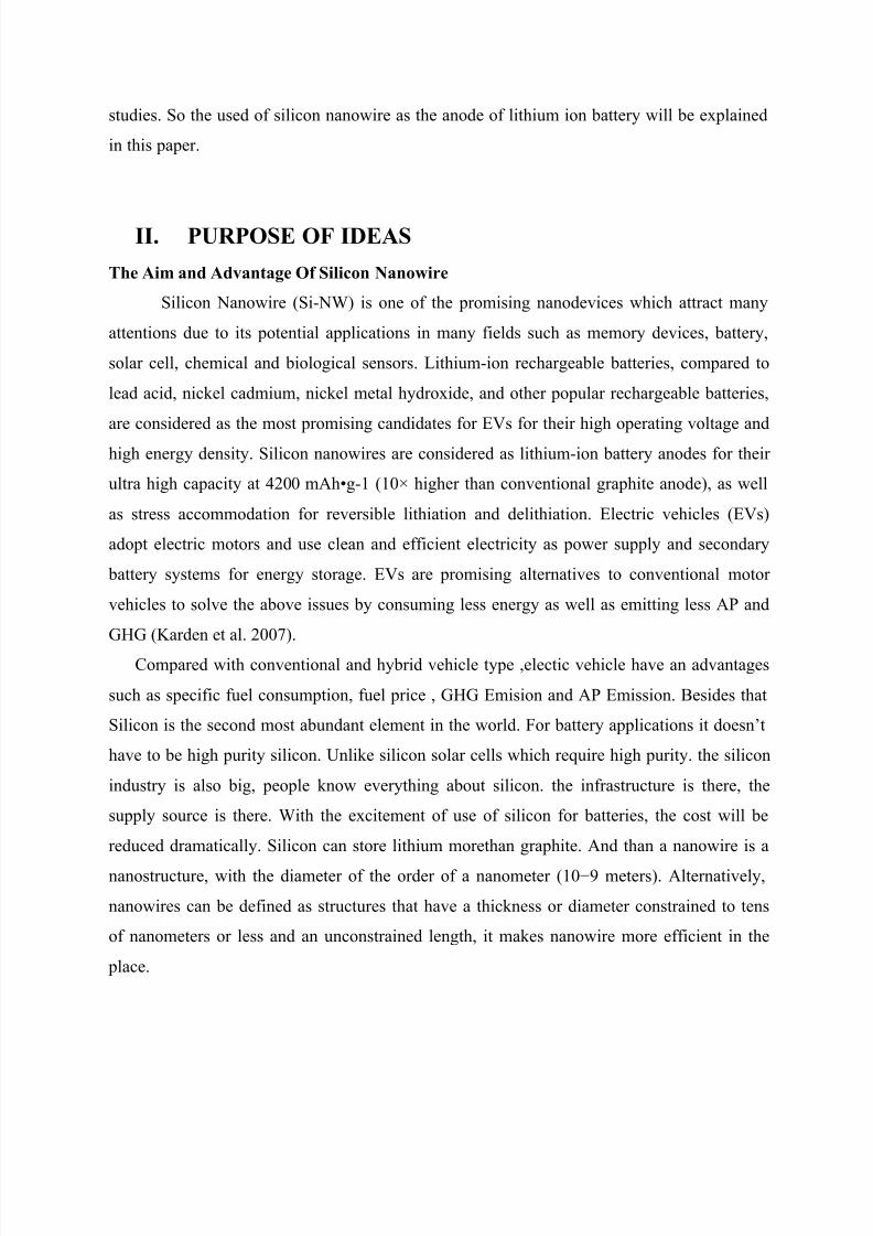
caused by the common vehicle. Here’s the comparison of fuel consumption and emissions
produced by different type of vehicle adapted from Electric and Hybrid Vehicle (Pistosia
According to the data, some big country such as US is now releasing $2.4 Billion in
federal funding to develop next generation batteries and electric vehicle. The previous battery
that is used for electric vehicle has a lower energy density than gasoline. The challange of
increasing of specific energy, cost and life span are concerns for battery of electronic vehicle
development. Compared with other popular rechargeable battery such as nickel cadmium,
lead acid and nickel metal hydroxide, Lithium ion battery is the most capable to be the
candidate of electronc vehicle since it has a high operating voltage, high anergy and also high
power density. Lately, graphite is used as the anode of lithium ion battery, but graphite shows
a limitation for the development of high capacity lithium-ion battery (theoretical specific
capacity of only 372 mAh·g-1). The study has found that silicon has highest capability in
safely storing lithium of 4200 mAh·g-1 at fully lithiated state (Li22Si4) among any
substances. But silicon can’t be directly used as an anode because of its volume expansion
over 300 % when fully lithiated. Silicon nanowire structures have shown great potential in
achieving high capacities as well as accommodating reversible volume change inrecent
7/22/2019 PDF Nanowire
http://slidepdf.com/reader/full/pdf-nanowire 3/18
studies. So the used of silicon nanowire as the anode of lithium ion battery will be explained
in this paper.
II. PURPOSE OF IDEAS
The Aim and Advantage Of Silicon Nanowire
Silicon Nanowire (Si-NW) is one of the promising nanodevices which attract many
attentions due to its potential applications in many fields such as memory devices, battery,
solar cell, chemical and biological sensors. Lithium-ion rechargeable batteries, compared to
lead acid, nickel cadmium, nickel metal hydroxide, and other popular rechargeable batteries,
are considered as the most promising candidates for EVs for their high operating voltage and
high energy density. Silicon nanowires are considered as lithium-ion battery anodes for their
ultra high capacity at 4200 mAh•g-1 (10× higher than conventional graphite anode), as well
as stress accommodation for reversible lithiation and delithiation. Electric vehicles (EVs)
adopt electric motors and use clean and efficient electricity as power supply and secondary
battery systems for energy storage. EVs are promising alternatives to conventional motor
vehicles to solve the above issues by consuming less energy as well as emitting less AP and
GHG (Karden et al. 2007).
Compared with conventional and hybrid vehicle type ,electic vehicle have an advantages
such as specific fuel consumption, fuel price , GHG Emision and AP Emission. Besides that
Silicon is the second most abundant element in the world. For battery applications it doesn’t
have to be high purity silicon. Unlike silicon solar cells which require high purity. the silicon
industry is also big, people know everything about silicon. the infrastructure is there, the
supply source is there. With the excitement of use of silicon for batteries, the cost will be
reduced dramatically. Silicon can store lithium morethan graphite. And than a nanowire is a
nanostructure, with the diameter of the order of a nanometer (10−9 meters). Alternatively,
nanowires can be defined as structures that have a thickness or diameter constrained to tens
of nanometers or less and an unconstrained length, it makes nanowire more efficient in the
place.
7/22/2019 PDF Nanowire
http://slidepdf.com/reader/full/pdf-nanowire 4/18
III. LITERATURE REVIEW
2.1Silicon Nanowire Fabrication and Integration via Nickel
Monosilicide ContactsSilicon nanowires can be fabricated and applied as lithium-ion battery anodes.
Electrical contacts between silicon nanowires and metal substrates are essential to nanowire
integration and applications. Metal silicides between silicon and metal are used as electrical
contacts for silicon. Among many metal silicides, nickel monosilicide (NiSi), due to its low
resistivity, low formation temperature, and low consumption of silicon, has been widely
applied in industrial processes to create low resistance ohmic electrical contacts between
planer silicon and substrates.
Silicon Nanowire Fabrication via Eectroless Etching
Silicon nanowires are fabricated via electroless etching of single crystal silicon wafer
in aqueous solution. P-type (boron doped) and n-type (phosphorus doped) single crystal
silicon wafer with (100) surface orientation and resistivity of 1-5 Ω・cm were obtained from
Montco Silicon Technologies, CA.
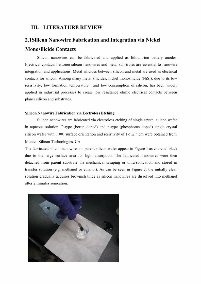
The fabricated silicon nanowires on parent silicon wafer appear in Figure 1 as charcoal blackdue to the large surface area for light absorption. The fabricated nanowires were then
detached from parent substrate via mechanical scraping or ultra-sonication and stored in
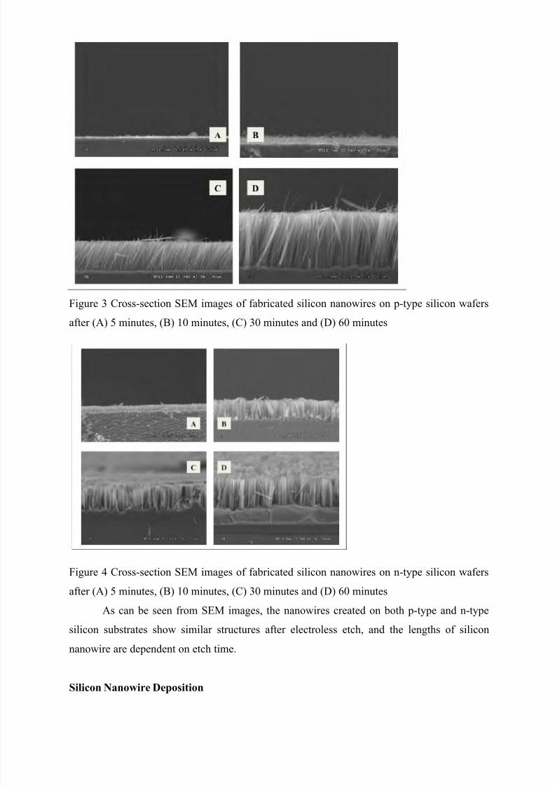
transfer solution (e.g. methanol or ethanol). As can be seen in Figure 2, the initially clear
solution gradually acquires brownish tinge as silicon nanowires are dissolved into methanol
after 2 minutes sonication.
7/22/2019 PDF Nanowire
http://slidepdf.com/reader/full/pdf-nanowire 5/18
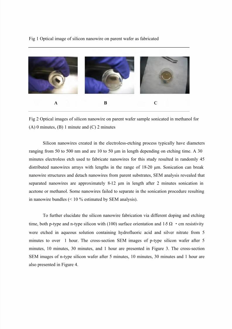
Fig 1 Optical image of silicon nanowire on parent wafer as fabricated
Fig 2 Optical images of silicon nanowire on parent wafer sample sonicated in methanol for
(A) 0 minutes, (B) 1 minute and (C) 2 minutes
Silicon nanowires created in the electroless-etching process typically have diameters
ranging from 50 to 500 nm and are 10 to 50 μm in length depending on etching time. A 30
minutes electroless etch used to fabricate nanowires for this study resulted in randomly 45
distributed nanowires arrays with lengths in the range of 18-20 μm. Sonication can break
nanowire structures and detach nanowires from parent substrates, SEM analysis revealed that
separated nanowires are approximately 8-12 μm in length after 2 minutes sonication in
acetone or methanol. Some nanowires failed to separate in the sonication procedure resulting
in nanowire bundles (< 10 % estimated by SEM analysis).
To further elucidate the silicon nanowire fabrication via different doping and etching
time, both p-type and n-type silicon with (100) surface orientation and 1-5 Ω・cm resistivity
were etched in aqueous solution containing hydrofluoric acid and silver nitrate from 5
minutes to over 1 hour. The cross-section SEM images of p-type silicon wafer after 5
minutes, 10 minutes, 30 minutes, and 1 hour are presented in Figure 3. The cross-section
SEM images of n-type silicon wafer after 5 minutes, 10 minutes, 30 minutes and 1 hour are
also presented in Figure 4.
7/22/2019 PDF Nanowire
http://slidepdf.com/reader/full/pdf-nanowire 6/18
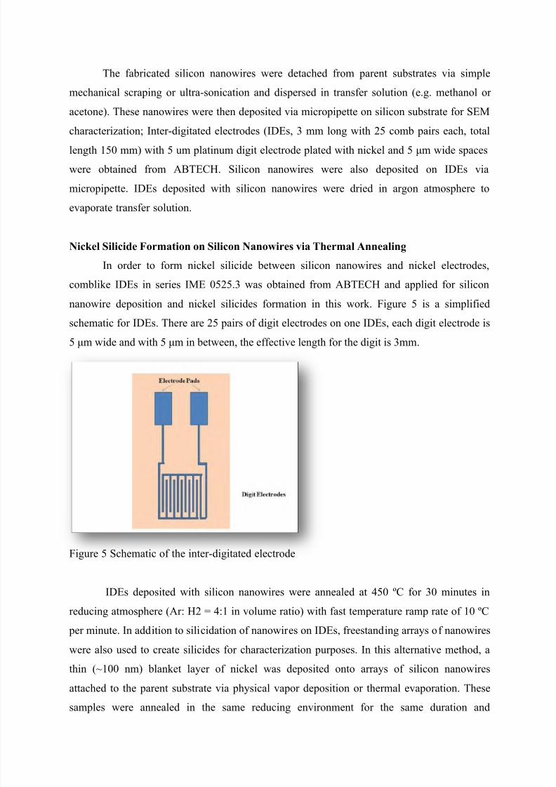
Figure 3 Cross-section SEM images of fabricated silicon nanowires on p-type silicon wafers
after (A) 5 minutes, (B) 10 minutes, (C) 30 minutes and (D) 60 minutes
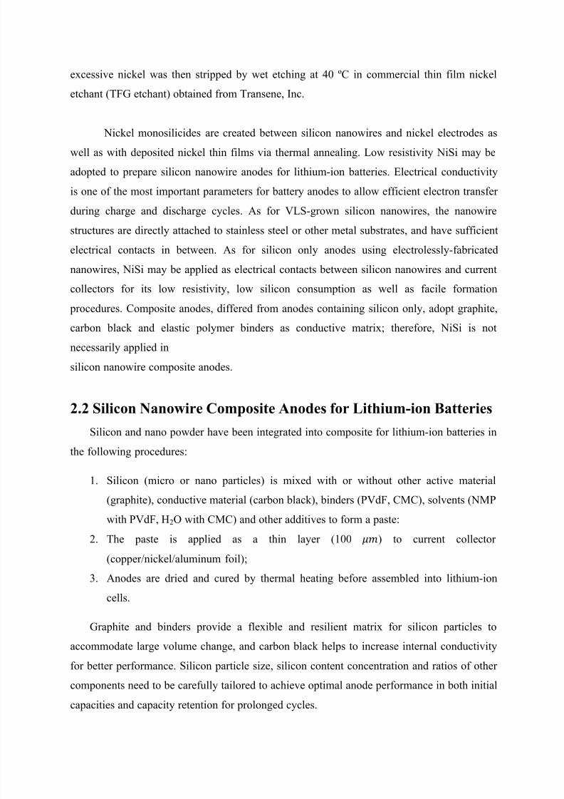
Figure 4 Cross-section SEM images of fabricated silicon nanowires on n-type silicon wafers
after (A) 5 minutes, (B) 10 minutes, (C) 30 minutes and (D) 60 minutes
As can be seen from SEM images, the nanowires created on both p-type and n-type
silicon substrates show similar structures after electroless etch, and the lengths of silicon
nanowire are dependent on etch time.
Silicon Nanowire Deposition
7/22/2019 PDF Nanowire
http://slidepdf.com/reader/full/pdf-nanowire 7/18
The fabricated silicon nanowires were detached from parent substrates via simple
mechanical scraping or ultra-sonication and dispersed in transfer solution (e.g. methanol or
acetone). These nanowires were then deposited via micropipette on silicon substrate for SEM
characterization; Inter-digitated electrodes (IDEs, 3 mm long with 25 comb pairs each, total
length 150 mm) with 5 um platinum digit electrode plated with nickel and 5 μm wide spaces
were obtained from ABTECH. Silicon nanowires were also deposited on IDEs via
micropipette. IDEs deposited with silicon nanowires were dried in argon atmosphere to
evaporate transfer solution.
Nickel Silicide Formation on Silicon Nanowires via Thermal Annealing
In order to form nickel silicide between silicon nanowires and nickel electrodes,
comblike IDEs in series IME 0525.3 was obtained from ABTECH and applied for silicon
nanowire deposition and nickel silicides formation in this work. Figure 5 is a simplified
schematic for IDEs. There are 25 pairs of digit electrodes on one IDEs, each digit electrode is
5 μm wide and with 5 μm in between, the effective length for the digit is 3mm.
Figure 5 Schematic of the inter-digitated electrode
IDEs deposited with silicon nanowires were annealed at 450 ºC for 30 minutes in
reducing atmosphere (Ar: H2 = 4:1 in volume ratio) with fast temperature ramp rate of 10 ºC
per minute. In addition to silicidation of nanowires on IDEs, freestanding arrays of nanowires
were also used to create silicides for characterization purposes. In this alternative method, a
thin (~100 nm) blanket layer of nickel was deposited onto arrays of silicon nanowires
attached to the parent substrate via physical vapor deposition or thermal evaporation. These
samples were annealed in the same reducing environment for the same duration and
7/22/2019 PDF Nanowire
http://slidepdf.com/reader/full/pdf-nanowire 8/18
excessive nickel was then stripped by wet etching at 40 ºC in commercial thin film nickel
etchant (TFG etchant) obtained from Transene, Inc.
Nickel monosilicides are created between silicon nanowires and nickel electrodes as
well as with deposited nickel thin films via thermal annealing. Low resistivity NiSi may be
adopted to prepare silicon nanowire anodes for lithium-ion batteries. Electrical conductivity
is one of the most important parameters for battery anodes to allow efficient electron transfer
during charge and discharge cycles. As for VLS-grown silicon nanowires, the nanowire
structures are directly attached to stainless steel or other metal substrates, and have sufficient
electrical contacts in between. As for silicon only anodes using electrolessly-fabricated
nanowires, NiSi may be applied as electrical contacts between silicon nanowires and current
collectors for its low resistivity, low silicon consumption as well as facile formation
carbon black and elastic polymer binders as conductive matrix; therefore, NiSi is not
necessarily applied in
silicon nanowire composite anodes.
2.2 Silicon Nanowire Composite Anodes for Lithium-ion Batteries
Silicon and nano powder have been integrated into composite for lithium-ion batteries in
the following procedures:
1. Silicon (micro or nano particles) is mixed with or without other active material
(graphite), conductive material (carbon black), binders (PVdF, CMC), solvents (NMP
with PVdF, H2O with CMC) and other additives to form a paste:
2. The paste is applied as a thin layer (100 ) to current collector
(copper/nickel/aluminum foil);
3. Anodes are dried and cured by thermal heating before assembled into lithium-ion
cells.
Graphite and binders provide a flexible and resilient matrix for silicon particles to
accommodate large volume change, and carbon black helps to increase internal conductivity
for better performance. Silicon particle size, silicon content concentration and ratios of other
components need to be carefully tailored to achieve optimal anode performance in both initial
capacities and capacity retention for prolonged cycles.
7/22/2019 PDF Nanowire
http://slidepdf.com/reader/full/pdf-nanowire 9/18
Types of methods have been applied to improve the reversible capacity and cycle life for
silicon composite anodes:
Combining silicon with lithium-inactive elements
Inactive material matrix has been studied for silicon composite anode to solve the
issues of volume change. Co, Fe,Ni,Ca,B and several other materials have been
studied; however the reversible capacities are reduced with presence of these inactive
materials, suggesting the replacecement for other materials.
Combining silicon with lithium-active elements
Beside carbon, silicon particles mixed with lithium active substances, such as Mg, Ag
and Snm have been studied as composite anodes.these lithium active additives react
with lithium to form alloy as well as silicon, serving as hosting matrix and conductive
path way for silicon particles.
Extensive studies have been focused on silicon thin film anodes, including
mechanism of lithium insertion, stress evolution within anodes during charge and
discharge cycles, surface film formation. Although thin film silicon anodes cracking
and pulverization have been observed after prolonged cycles, the capacity retention
reversibility of thin film silicon are greatly improved compared to silicon compositeanodes. It has been demonstrated that the thinner silicon film is the bertter it performs
in both capacity retention and cycle ability.
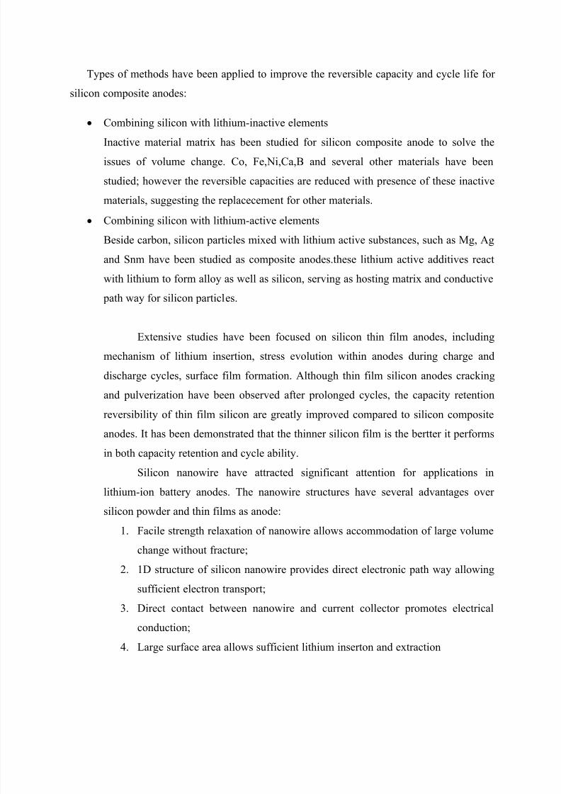
Silicon nanowire have attracted significant attention for applications in
lithium-ion battery anodes. The nanowire structures have several advantages over
silicon powder and thin films as anode:
1. Facile strength relaxation of nanowire allows accommodation of large volume
change without fracture;
2. 1D structure of silicon nanowire provides direct electronic path way allowing
sufficient electron transport;
3. Direct contact between nanowire and current collector promotes electrical
conduction;
4. Large surface area allows sufficient lithium inserton and extraction
Silicon nanowire anodes synthesized via Vapor-Liquid-Solid (VLS) grown are
capable of accommodating volume changes caused by lithium insertion and extraction
with near theoretical capacities. As shown at above, the VLS-grown nanowires
undergo reversible lithium nsertion and extraction without significant pulverization ordetachment from the curreny collector. The VLS-grown slicon nanowire anodes
maintain reversible capacity for over 2000 mAh/g after 80 consecutive cycles.
Solid Electrolyte Interphase (SEI)
The SEI is defined as thin layer (30-50 nm) composed of organic and
inorganic products deposited on the anode surface during charge and discharge cycles
due to electrolyte reduction and other surface reactions.
Solid Electrolyte Interphase on silicon anodes
SEI layer on silicon anodes is significantly different from the film typically formed on
graphite negative electrodes for two main reasons:
1. The silicon surface is more reactive to electrolytes than graphite and will resukt in o
complex SEI composition that includes hydrocarbons, C2H5OCOOLi, LiCO3, Li2O,
LiF and silicon containing products (such as lithium silicates, SiF6
2. Over 300% volume change for silicon during lithium insertion and extraction may
cause breakage of the SEI and expose reactive silicon suface to electrolytes for further
undesired reactions.
2.3 Surface Chemistry and Solid Electrolyte Interphase (SEI)
of Silicon Nanowire Anodes
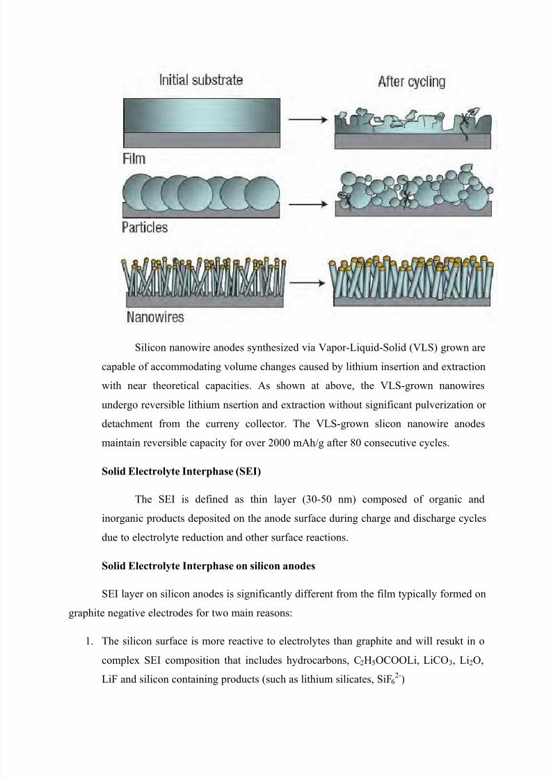
Silicon Nanowire Array Anodes
Figure 6 shows silicon nanowires created in this process are approximately 30 μm in
length and range from 50 to 500 nm in diameter (average diameter of 253 ± 91 nm 1σ)after 30 minutes of electroless etching. Nitric acid was used to strip silver dendrites
followed by a BOE treatment to remove oxides and provide a hydride-terminated surface.
All electrochemical measurements were carried out with nanowires attached to the bulk
silicon substrate or detached from substrate and combined with graphite (in case of
composite anodes). Ohmic loses across the bulk silicon substrate (500 μm thick) were
negligible due to the relatively low resistivity (1-5 Ω cm) of the parent wafer.
Figure 6 SEM image of silicon nanowire arrays on parent substrate as fabricated
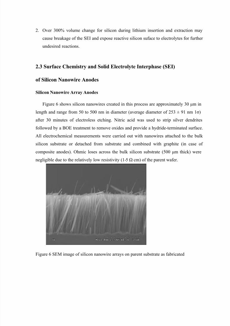
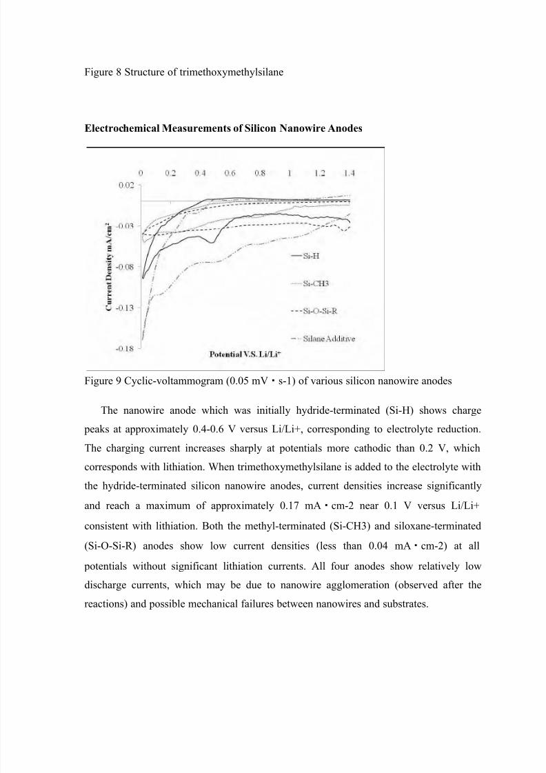
Charge and Discharge for Silicon Nanowire Composite Anodes with Modified
Silicon Surfaces
While silicon nanowire anodes offer a homogeneous substrate for analytical purposes,
their use as reversible anodes in this form is severely limited due to agglomeration upon
cycling. For this reason, we evaluated the capacity and cycle performance of
functionalized silicon anodes using composite anodes. Silicon nanowire composite
anodes (containing 15 % silicon nanowire and 85 % graphite as active material) including
hydride-terminated, methylated, siloxane terminated were also prepared and cycled in
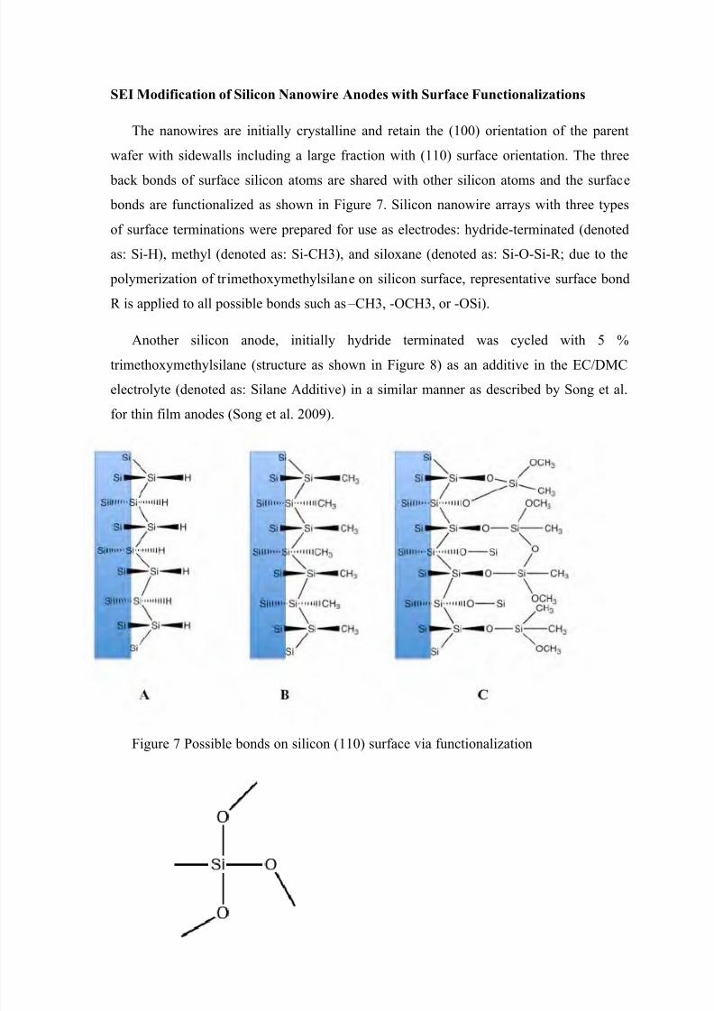
lithium-ion half cells. Another hydrideterminated silicon nanowire composite was cycled
in lithium-ion half cell with trimethoxymethylsilane additive. As can be observed from
SEM images, silicon nanowires are randomly distributed among graphite flakes in the
composite anode as prepared (Figure 68 A); while after 15 successive charge and
discharge cycles, the anode surface is covered with an observable organic layer (SEI
layer) as shown in Figure 68 B. charge and discharge cycles, the anode surface is covered
with an observable organic layer (SEI layer) as shown in Figure 10 B.
Figure 10 SEM images of silicon nanowire composite anodes (A) before and (B) after
15 charge/discharge cycles
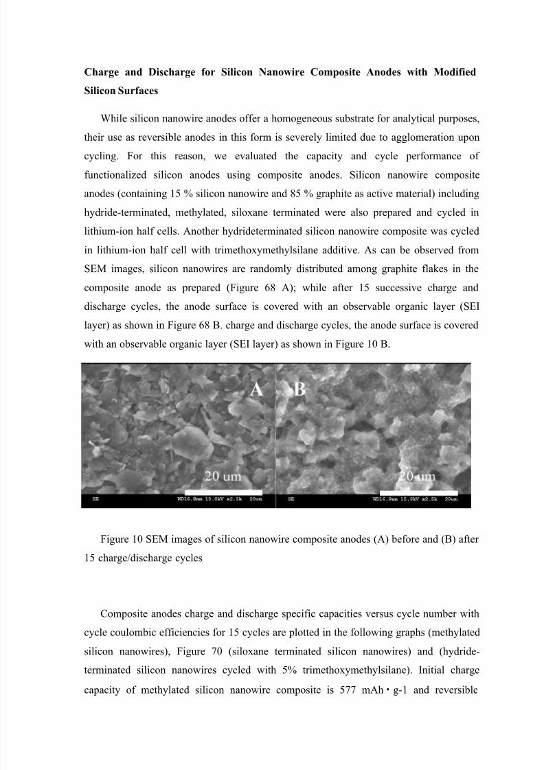
Composite anodes charge and discharge specific capacities versus cycle number with
cycle coulombic efficiencies for 15 cycles are plotted in the following graphs (methylated
silicon nanowires), Figure 70 (siloxane terminated silicon nanowires) and (hydride-
terminated silicon nanowires cycled with 5% trimethoxymethylsilane). Initial chargecapacity of methylated silicon nanowire composite is 577 mAh・g-1 and reversible