USER’S MANUAL FOR THE NATIONAL WATER INFORMATION SYSTEM OF THE U.S. GEOLOGICAL SURVEY GROUND-WATER SITE-INVENTORY SYSTEM U.S. GEOLOGICAL SURVEY OF 2004-1238 Version 4.3 Reston, Virginia 2004
Transcript
USER’S MANUAL FOR THE NATIONAL WATER INFORMATION SYSTEM OF THE U.S. GEOLOGICAL SURVEY GROUND-WATER SITE-INVENTORY SYSTEM U.S. GEOLOGICAL SURVEY OF 2004-1238 Version 4.3
Reston, Virginia 2004
U.S. DEPARTMENT OF THE INTERIOR Gale A. Norton, Secretary U.S. GEOLOGICAL SURVEY Charles G. Groat, Director The use of trade, product, or firm names in this report is for descriptive purposes only and does not imply endorsement by the U.S. Government. ________________________________________________________________________ For additional information write to: Copies of this report can be obtained from: U.S. Geological Survey U.S. Geological Survey Water Resources Division Water Resources Division NWIS Testing, Data Transfer, Support NWIS Testing, Data Transfer, Support and Maintenance Unit, Mail Stop 437 and Maintenance Unit, Mail Stop 437 12201 Sunrise Valley Drive 12201 Sunrise Valley Drive Reston, VA 20192 Reston, VA 20192 This report is accessible online at: http://pubs.water.usgs.gov/ofr20041238/
Table of Contents
Table of Contents
Release 4.3
ABSTRACT…………………………………………………………………………….………..1
CHAPTER 1 INTRODUCTION..................................................................................... 1 1.1 MANAGEMENT OVERVIEW ........................................................................................ .1 1.2 DESCRIPTION OF THE GROUND-WATER SITE-INVENTORY ......................................... 2 1.3 PURPOSE OF THE MANUAL ......................................................................................... 3 1.4 ACKNOWLEDGEMENTS............................................................................................... 6 1.5 SELECTED REFERENCES ............................................................................................. 6
CHAPTER 2 NWIS SITE FILE AND GROUND-WATER SITE-INVENTORY CODING INSTRUCTIONS............................................................................................. 7
CHAPTER 2, SECTION 1 SITEFILE COMPONENTS............................................. 9 1.1 SOURCE AGENCY CODE .......................................................................................... 10 1.2 SITE IDENTIFICATION NUMBER ............................................................................... 10 1.3 PERSON CREATING RECORD ................................................................................... 12 1.4 DATE CREATED....................................................................................................... 12 1.5 PERSON UPDATING RECORD ................................................................................... 13 1.6 DATE OF LAST UPDATE........................................................................................... 13 1.7 PROJECT NUMBER................................................................................................... 13 1.8 LOCAL NUMBER OR STATION NAME....................................................................... 13 1.9 STATION TYPE ........................................................................................................ 13 1.10 DISTRICT CODE..................................................................................................... 16 1.11 COUNTRY CODE.................................................................................................... 16 1.12 STATE CODE ......................................................................................................... 17 1.13 COUNTY CODE...................................................................................................... 17 1.14 LATITUDE ............................................................................................................. 17 1.15 LONGITUDE........................................................................................................... 17 1.16 LATITUDE NAD83 ( DECIMAL DEGREES) ............................................................... 18 1.17 LONGITUDE NAD83 (DECIMAL DEGREES) ............................................................. 18 1.18 LAT/LONG COORDINATE ACCURACY.................................................................... 18 1.19 LAT/LONG METHOD ............................................................................................. 19 1.20 LAT/LONG DATUM ............................................................................................... 19 1.21 ALTITUDE OF LAND SURFACE............................................................................... 19 1.22 ALTITUDE ACCURACY .......................................................................................... 20 1.23 METHOD ALTITUDE DETERMINED ........................................................................ 20 1.24 ALTITUDE DATUM ................................................................................................ 20 1.25 LAND-NET LOCATION........................................................................................... 21 1.26 TOPOGRAPHIC-SETTING CODE.............................................................................. 21 1.27 HYDROLOGIC-UNIT CODE..................................................................................... 24 1.28 DRAINAGE-BASIN CODE ....................................................................................... 25 1.29 TIME ZONE CODE.................................................................................................. 25
Ground Water NWIS User i
Table of Contents
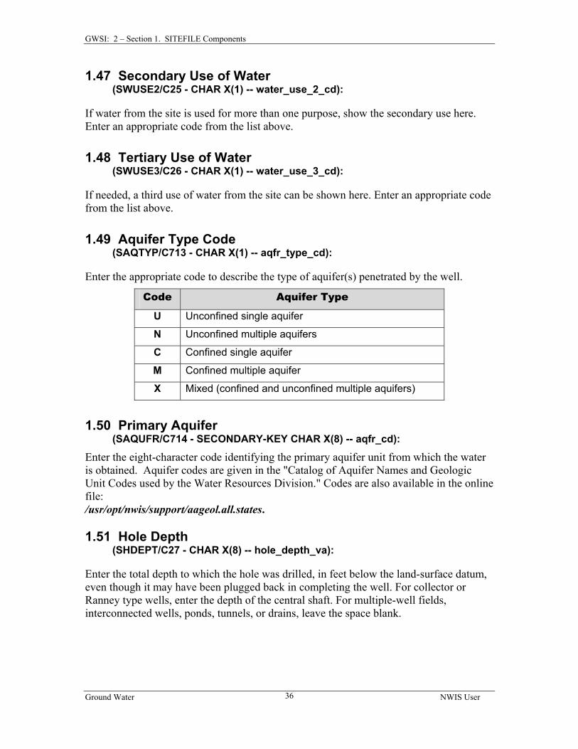
1.30 LOCAL STANDARD TIME FLAG ............................................................................. 25 1.31 LOCATION MAP .................................................................................................... 25 1.32 MAP SCALE........................................................................................................... 25 1.33 AGENCY USE OF SITE............................................................................................ 26 1.34 NATIONAL WATER-USE CODE .............................................................................. 26 1.35 TYPE OF DATA COLLECTED .................................................................................. 27 1.36 INSTRUMENTS AT SITE .......................................................................................... 28 1.37 DATE SITE ESTABLISHED OR INVENTORIED .......................................................... 29 1.38 REMARKS.............................................................................................................. 29 1.39 TYPE OF GROUND-WATER SITE ............................................................................ 29 1.40 RECORD READY FOR WEB .................................................................................... 30 1.41 DATA RELIABILITY CODE ..................................................................................... 31 1.42 DATE OF FIRST CONSTRUCTION............................................................................ 31 1.43 PRIMARY USE OF SITE .......................................................................................... 31 1.44 SECONDARY SITE USE .......................................................................................... 33 1.45 TERTIARY SITE USE .............................................................................................. 33 1.46 PRIMARY USE OF WATER...................................................................................... 33 1.47 SECONDARY USE OF WATER................................................................................. 36 1.48 TERTIARY USE OF WATER .................................................................................... 36 1.49 AQUIFER TYPE CODE ............................................................................................ 36 1.50 PRIMARY AQUIFER ............................................................................................... 36 1.51 HOLE DEPTH......................................................................................................... 36 1.52 WELL DEPTH ........................................................................................................ 37 1.53 SOURCE OF DEPTH DATA...................................................................................... 37 1.54 DRAINAGE AREA .................................................................................................. 37 1.55 CONTRIBUTING DRAINAGE AREA ......................................................................... 37 1.56 OTHER GROUND-WATER DATA FILES……………………………………………38
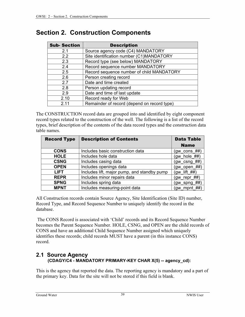
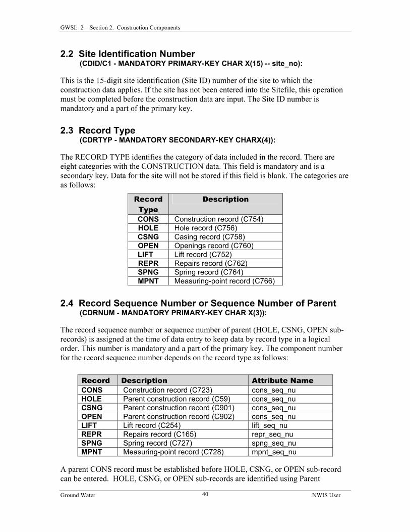
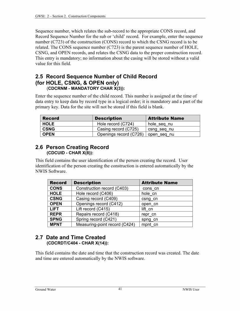
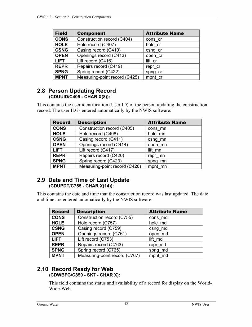
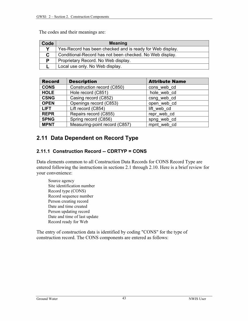
CHAPTER 2, SECTION 2 CONSTRUCTION COMPONENTS............................. 39 2.1 SOURCE AGENCY .................................................................................................... 39 2.2 SITE IDENTIFICATION NUMBER ............................................................................... 40 2.3 RECORD TYPE......................................................................................................... 40 2.4 RECORD SEQUENCE NUMBER OR SEQUENCE NUMBER OF PARENT ......................... 40 2.5 RECORD SEQUENCE NUMBER OF CHILD RECORD………………………….………41 2.6 PERSON CREATING RECORD ................................................................................... 41 2.7 DATE AND TIME CREATED...................................................................................... 41 2.8 PERSON UPDATING RECORD ................................................................................... 42 2.9 DATE AND TIME OF LAST UPDATE.......................................................................... 42 2.10 RECORD READY FOR WEB .................................................................................... 42 2.11 DATA DEPENDENT ON RECORD TYPE ................................................................... 43
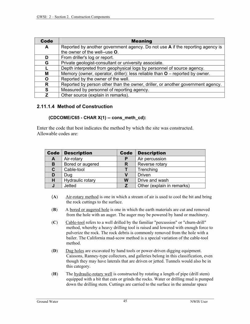
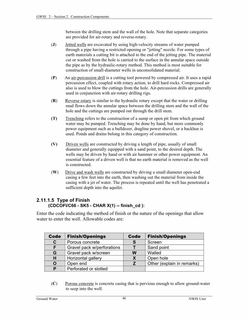
2.11.1 Construction Record .................................................................................... 43 2.11.1.1 Date of Completed Construction ........................................................... 44 2.11.1.2 Name of Contractor/Driller.................................................................... 44 2.11.1.3 Source of Construction Data.................................................................. 44 2.11.1.4 Method of Construction ......................................................................... 45 2.11.1.5 Type of Finish ........................................................................................ 46 2.11.1.6 Type of Seal ........................................................................................... 47
Ground Water NWIS User ii
Table of Contents
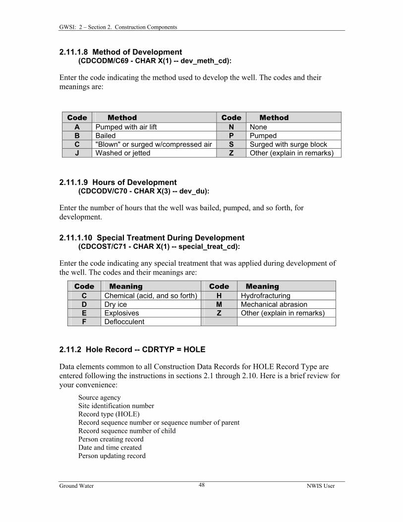
2.11.1.7 Depth to Bottom of Seal ........................................................................ 47 2.11.1.8 Method of Development ........................................................................ 48 2.11.1.9 Hours of Development........................................................................... 48 2.11.1.10 Special Treatment During Development ............................................. 48
2.11.2 Hole Record ................................................................................................. 48 2.11.2.1 Depth to Top of Interval ........................................................................ 49 2.11.2.2 Depth to Bottom of Interval................................................................... 49 2.11.2.3 Diameter of Interval............................................................................... 49
2.11.3 Casing Record……………..….………………………………………………………………….49 2.11.3.1 Depth to Top of Casing.......................................................................... 50 2.11.3.2 Depth to Bottom of Casing .................................................................... 50 2.11.3.3 Diameter of Casing ................................................................................ 50 2.11.3.4 Casing Material...................................................................................... 50 2.11.3.5 Casing Thickness ................................................................................... 51
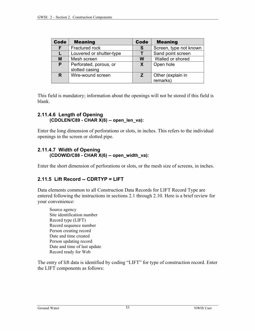
2.11.4 Openings Record .......................................................................................... 51 2.11.4.1 Depth to Top of Opening Interval.......................................................... 52 2.11.4.2 Depth to Bottom of Opening Interval .................................................... 52 2.11.4.3 Diameter of Opening Interval ................................................................ 52 2.11.4.4 Material Type......................................................................................... 52 2.11.4.5 Type of Opening .................................................................................... 52 2.11.4.6 Length of Opening ................................................................................. 53 2.11.4.7 Width of Opening .................................................................................. 53
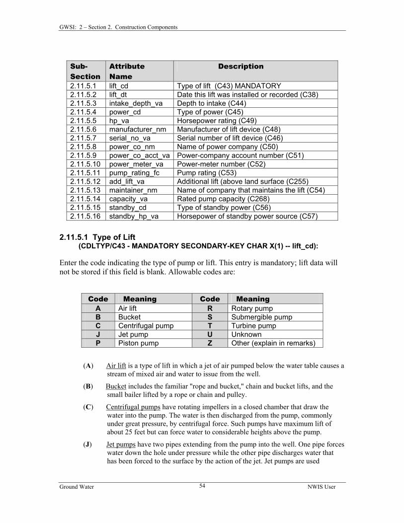
2.11.5 Lift Record ................................................................................................... 53 2.11.5.1 Type of Lift ............................................................................................ 54 2.11.5.2 Date Lift Installed or Recorded.............................................................. 55 2.11.5.3 Depth to Intake....................................................................................... 55 2.11.5.4 Type of Power........................................................................................ 55 2.11.5.5 Horsepower Rating ................................................................................ 56 2.11.5.6 Manufacturer of Lift Device .................................................................. 56 2.11.5.7 Serial Number of Lift Device ................................................................ 56 2.11.5.8 Name of Power Company...................................................................... 56 2.11.5.9 Power Company Account No. ............................................................... 56 2.11.5.10 Power Meter No................................................................................... 56 2.11.5.11 Pump Rating......................................................................................... 56 2.11.5.12 Additional Lift ..................................................................................... 57 2.11.5.13 Person or Company Who Maintains the Pump.................................... 57 2.11.5.14 Rated Pump Capacity........................................................................... 57 2.11.5.15 Type of Standby Power........................................................................ 57 2.11.5.16 Horsepower of Standby Power ............................................................ 57
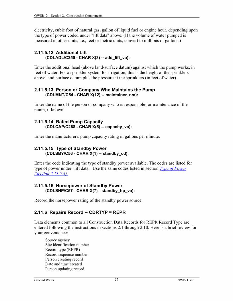
2.11.6 Repairs Record ............................................................................................. 57 2.11.6.1 Nature of Repair..................................................................................... 58 2.11.6.2 Date of Repair ........................................................................................ 58 2.11.6.3 Name of Contractor................................................................................ 58 2.11.6.4 Percent Performance Change................................................................. 58
2.11.7 Spring Record .............................................................................................. 59 2.11.7.1 Name of Spring ...................................................................................... 59
Ground Water NWIS User iii
Table of Contents
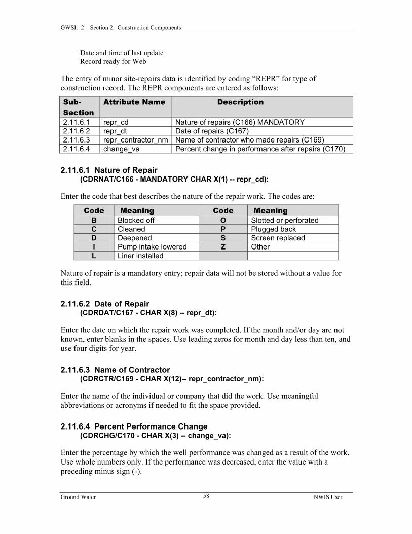
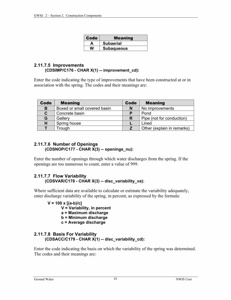
2.11.7.2 Type of Spring ....................................................................................... 59 2.11.7.3 Permanence ............................................................................................ 60 2.11.7.4 Sphere of Discharge............................................................................... 60 2.11.7.5 Improvements ........................................................................................ 61 2.11.7.6 Number of Openings.............................................................................. 61 2.11.7.7 Flow Variability ..................................................................................... 61 2.11.7.8 Basis For Variability .............................................................................. 61
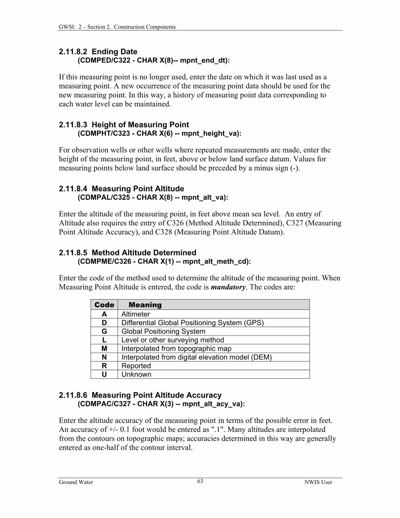
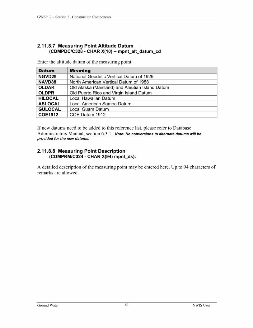
2.11.8 Measuring-Point Record .............................................................................. 62 2.11.8.1 Beginning Date ...................................................................................... 62 2.11.8.2 Ending Date ........................................................................................... 63 2.11.8.3 Height of Measuring Point..................................................................... 63 2.11.8.4 Measuring Point Altitude....................................................................... 63 2.11.8.5 Method Altitude Determined ................................................................. 63 2.11.8.6 Measuring Point Altitude Accuracy....................................................... 63 2.11.8.7 Measuring Point Altitude Datum........................................................... 64 2.11.8.8 Measuring Point Description ................................................................. 64
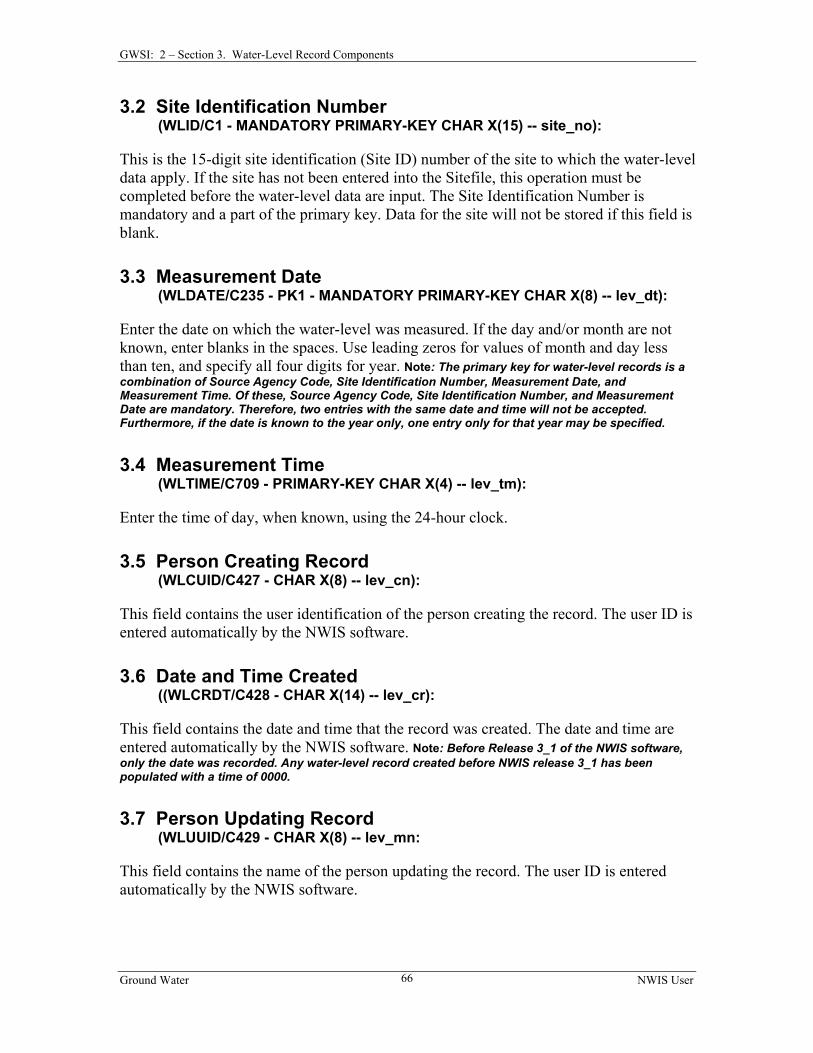
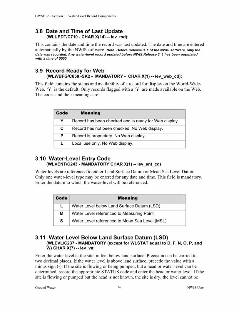
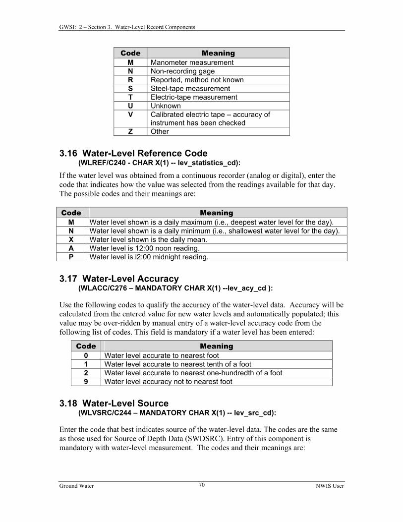
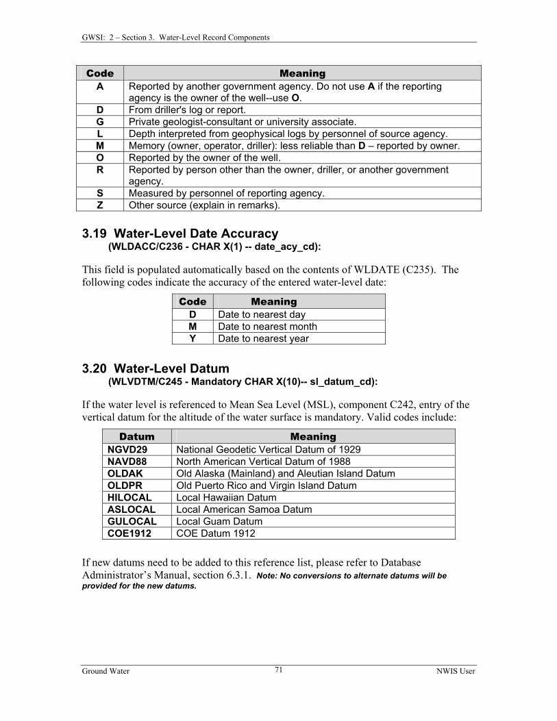
CHAPTER 2, SECTION 3 WATER-LEVEL RECORD COMPONENTS............. 65 3.1 SOURCE AGENCY CODE .......................................................................................... 65 3.2 SITE IDENTIFICATION NUMBER ............................................................................... 66 3.3 MEASUREMENT DATE............................................................................................. 66 3.4 MEASUREMENT TIME.............................................................................................. 66 3.5 PERSON CREATING RECORD ................................................................................... 66 3.6 DATE AND TIME CREATED...................................................................................... 66 3.7 PERSON UPDATING RECORD ................................................................................... 66 3.8 DATE AND TIME OF LAST UPDATE.......................................................................... 67 3.9 RECORD READY FOR WEB ...................................................................................... 67 3.10 WATER-LEVEL ENTRY CODE................................................................................ 67 3.11 WATER-LEVEL BELOW LAND SURFACE DATUM (LSD)....................................... 67 3.12 WATER-LEVEL REFERENCED TO MEASURING POINT............................................ 68 3.13 WATER-LEVEL REFERENCED TO MEAN SEA LEVEL (MSL).................................. 68 3.14 WATER-LEVEL STATUS ........................................................................................ 68 3.15 WATER-LEVEL METHOD OF MEASUREMENT ........................................................ 69 3.16 WATER-LEVEL STATISTICS CODE......................................................................... 70 3.17 WATER-LEVEL ACCURACY................................................................................... 70 3.18 WATER-LEVEL SOURCE........................................................................................ 70 3.19 WATER-LEVEL DATE ACCURACY......................................................................... 71 3.20 WATER-LEVEL DATUM......................................................................................... 71 3.21 WATER-LEVEL PARTY .......................................................................................... 72 3.22 SOURCE AGENCY .................................................................................................. 72 3.23 SEQUENCE NUMBER OF MP RECORD.................................................................... 72
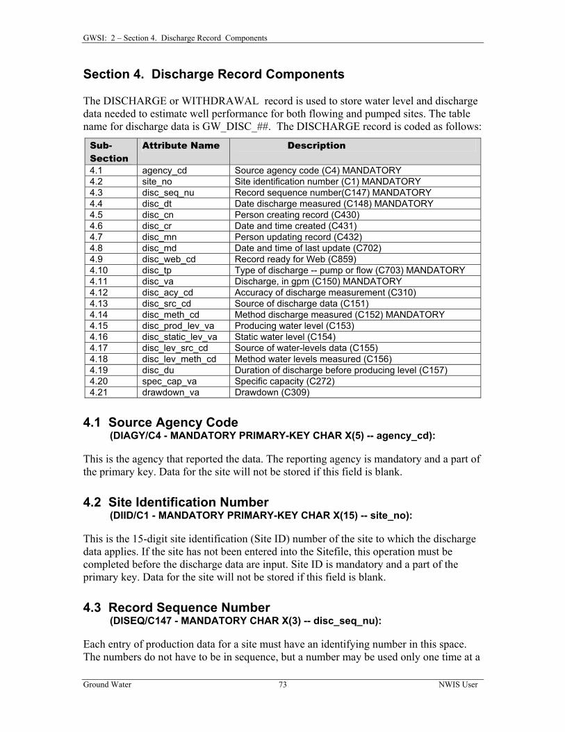
CHAPTER 2, SECTION 4 DISCHARGE RECORD COMPONENTS................... 73 4.1 SOURCE AGENCY CODE .......................................................................................... 73 4.2 SITE IDENTIFICATION NUMBER ............................................................................... 73 4.3 RECORD SEQUENCE NUMBER ................................................................................. 73 4.4 DATE DISCHARGE MEASURED ................................................................................ 74
Ground Water NWIS User iv
Table of Contents
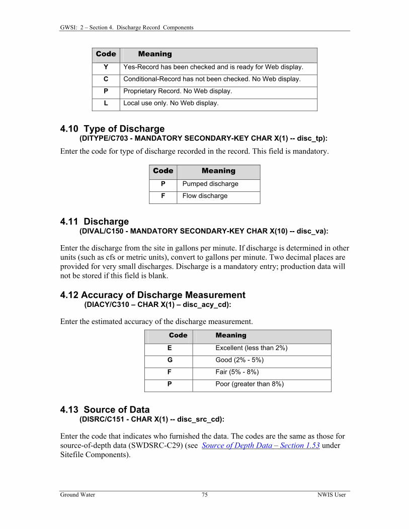
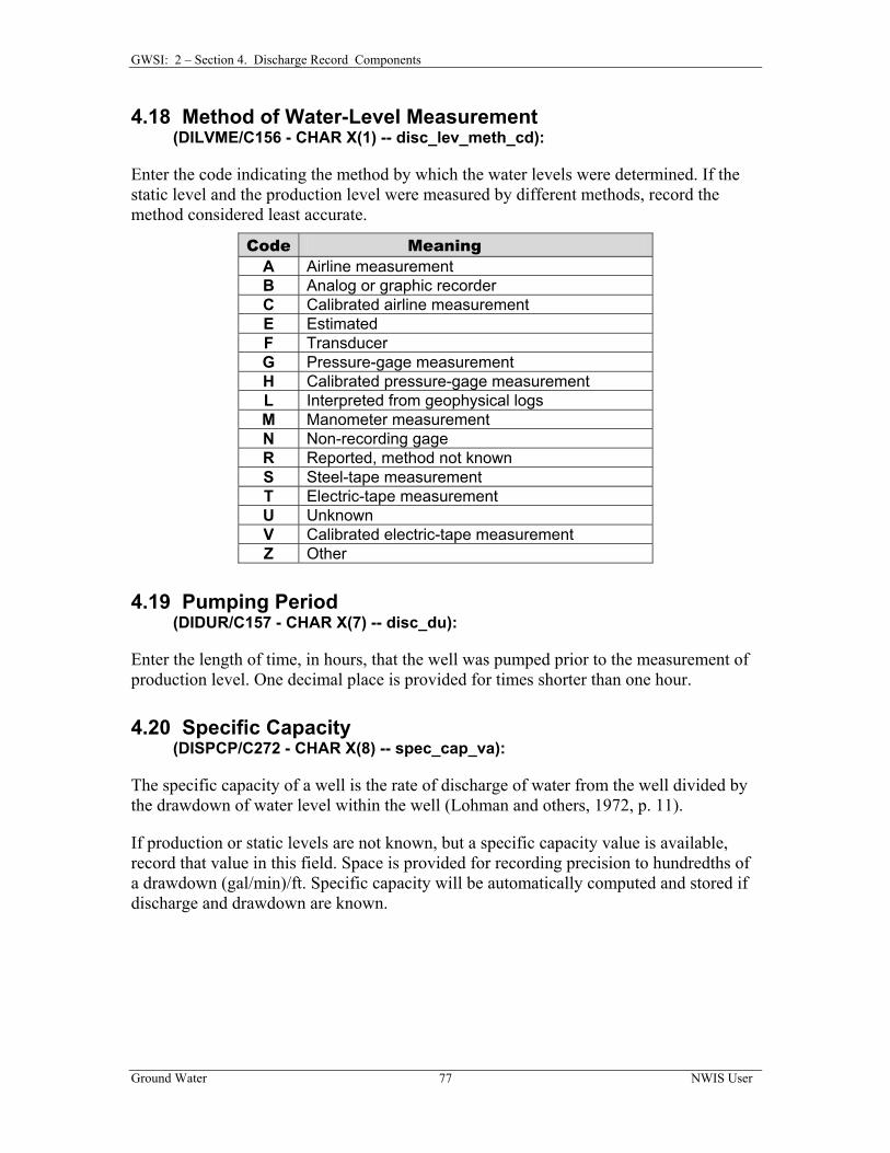
4.5 PERSON CREATING RECORD ................................................................................... 74 4.6 DATE AND TIME CREATED...................................................................................... 74 4.7 PERSON UPDATING RECORD ................................................................................... 74 4.8 DATE AND TIME OF LAST UPDATE.......................................................................... 74 4.9 RECORD READY FOR WEB ...................................................................................... 74 4.10 TYPE OF DISCHARGE............................................................................................. 75 4.11 DISCHARGE........................................................................................................... 75 4.12 ACCURACY OF DISCHARGE MEASUREMENT……………………………………...75 4.13 SOURCE OF DATA.................................................................................................. 75 4.14 METHOD OF DISCHARGE MEASUREMENT ............................................................. 76 4.15 PRODUCTION LEVEL ............................................................................................. 76 4.16 STATIC LEVEL....................................................................................................... 76 4.17 SOURCE OF DATA.................................................................................................. 76 4.18 METHOD OF WATER-LEVEL MEASUREMENT ........................................................ 77 4.19 PUMPING PERIOD .................................................................................................. 77 4.20 SPECIFIC CAPACITY .............................................................................................. 77 4.21 DRAWDOWN ......................................................................................................... 78
CHAPTER 2, SECTION 5 MISCELLANEOUS RECORD COMPONENTS........ 79 5.1 SOURCE AGENCY CODE .......................................................................................... 79 5.2 SITE IDENTIFICATION NUMBER ............................................................................... 79 5.3 RECORD TYPE......................................................................................................... 80 5.4 RECORD SEQUENCE NUMBER ................................................................................. 80 5.5 PERSON CREATING RECORD ................................................................................... 81 5.6 DATE AND TIME CREATED...................................................................................... 81 5.7 PERSON UPDATING RECORD ................................................................................... 82 5.8 DATE AND TIME OF LAST UPDATE.......................................................................... 82 5.9 RECORD READY FOR WEB ...................................................................................... 82 5.10 DATA DEPENDENT ON RECORD TYPE................................................................... 83
5.10.1 Owner's Record ............................................................................................ 83 5.10.1.1 Date of Ownership .................................................................................. 84
5.10.1.2 WU Owner Type………………………………………………………. 84 5.10.1.3 Owner's Name......................................................................................... 84 5.10.1.4 Owner’s Alias Name............................................................................... 84 5.10.1.5 Owner’s Phone Number.......................................................................... 85 5.10.1.6 Access to Owner’s Name........................................................................ 85 5.10.1.7 Owner’s Address Line 1 ......................................................................... 85 5.10.1.8 Owner’s Address Line 2 ......................................................................... 85 5.10.1.9 Owner’s City Name ................................................................................ 86 5.10.1.10 Owner’s Postal Code............................................................................. 86 5.10.1.11 Owner’s Zip Code................................................................................. 86 5.10.1.12 Owner’s Country Name ........................................................................ 86
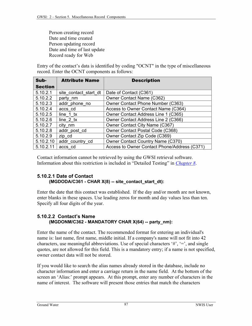
5.10.1.13 Access to Owner’s Phone/Address……………...………………..…....86 5.10.2 Contact’s Record .......................................................................................... 86
5.10.2.1 Date of Contact ....................................................................................... 87 5.10.2.2 Contact’s Name....................................................................................... 87 5.10.2.3 Contact’s Phone Number ........................................................................ 88
Ground Water NWIS User v
Table of Contents
5.10.2.4 Access to Contact’s Name ...................................................................... 88 5.10.2.5 Contact’s Address Line 1........................................................................ 88 5.10.2.6 Contact’s Address Line 2........................................................................ 88 5.10.2.7 Contact’s City Name............................................................................... 88 5.10.2.8 Contact’s Postal Code ............................................................................. 88 5.10.2.9 Contact’s Zip Code ................................................................................. 89 5.10.2.10 Contact’s Country Name....................................................................... 89 5.10.2.11 Access to Contact’s Phone/Address...................................................... 89
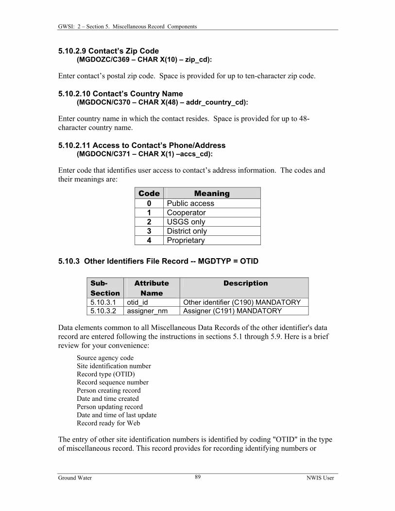
5.10.3 Other Identifiers File Record ....................................................................... 89 5.10.3.1 Other Identifier....................................................................................... 90 5.10.3.2 Assigner ................................................................................................. 90
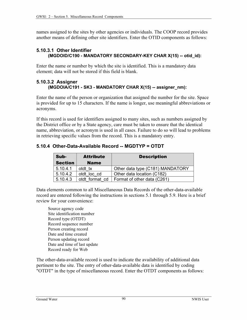
5.10.4 Other-Data-Available Record ...................................................................... 90 5.10.4.1 Other Data Type..................................................................................... 91 5.10.4.2 Other Data Location............................................................................... 91 5.10.4.3 Format .................................................................................................... 91
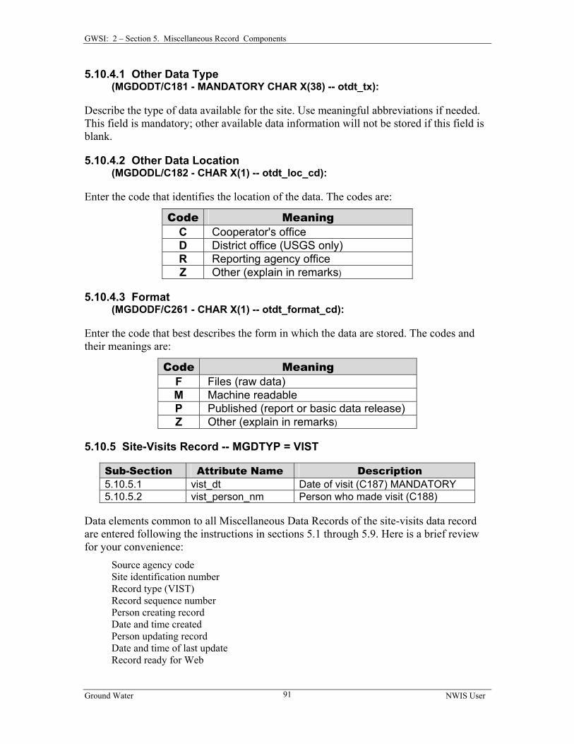
5.10.5 Site-Visits Record ........................................................................................ 91 5.10.5.1 Date of Visit........................................................................................... 92 5.10.5.2 Name of Person...................................................................................... 92
5.10.6 Field Water-Quality Record ......................................................................... 92 5.10.7 Geophysical-Logs Record ............................................................................ 92
5.10.7.1 Type of Log............................................................................................ 93 5.10.7.2 Beginning Depth .................................................................................... 94 5.10.7.3 Ending Depth ......................................................................................... 94 5.10.7.4 Source of Log Data ................................................................................ 94 5.10.7.5 Format of Log Data................................................................................. 94 5.10.7.6 Location of Log Data .............................................................................. 95
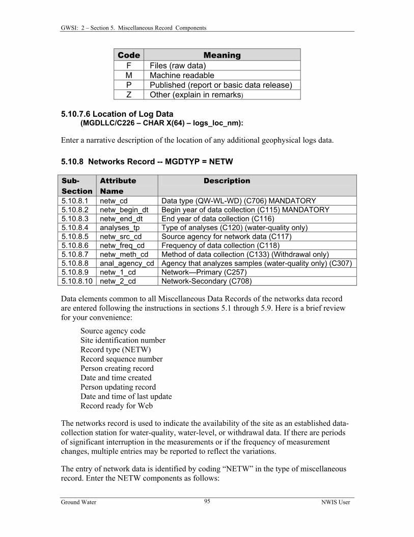
5.10.8 Networks Record ......................................................................................... 95 5.10.8.1 Type of Network .................................................................................... 96 5.10.8.2 Beginning Year ...................................................................................... 96 5.10.8.3 Ending Year ........................................................................................... 96 5.10.8.4 Type of Analyses ................................................................................... 96 5.10.8.5 Source Agency For Network Data......................................................... 97 5.10.8.6 Frequency of Collection......................................................................... 97 5.10.8.7 Method of Collection ............................................................................. 97 5.10.8.8 Analyzing Agency ................................................................................. 97 5.10.8.9 Primary Network Site ............................................................................ 98 5.10.8.10 Secondary Network Site ...................................................................... 98
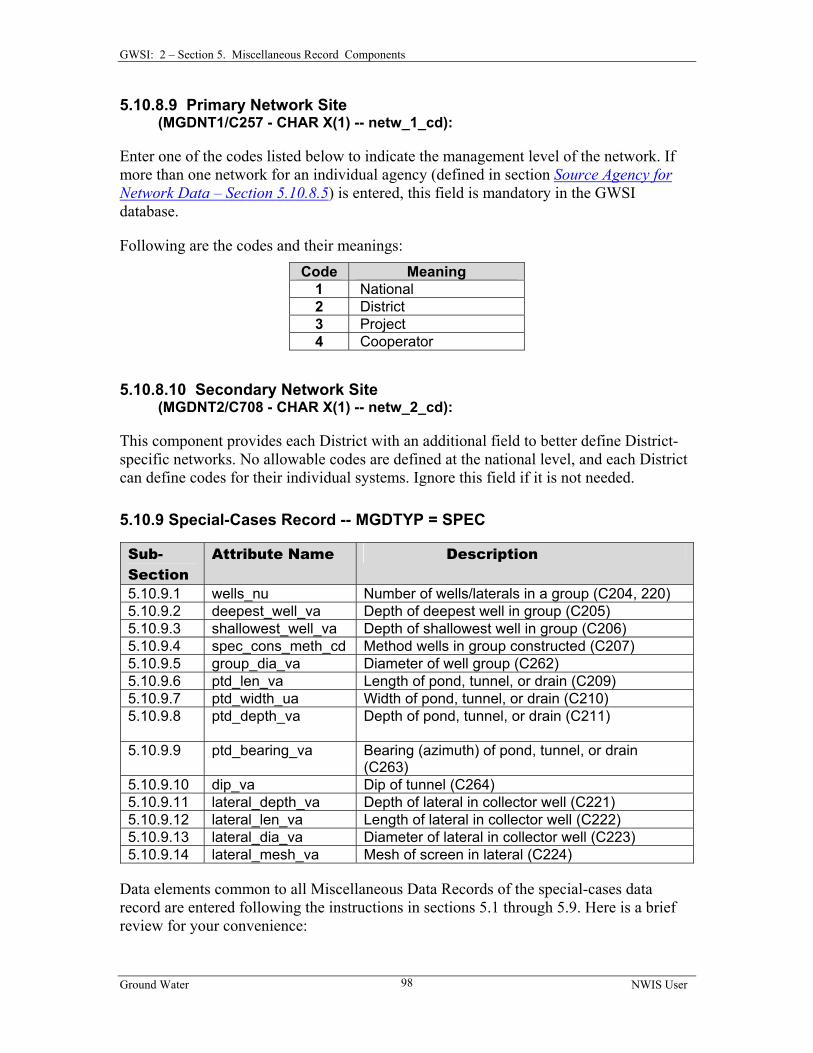
5.10.9 Special-Cases Record .................................................................................... 98 5.10.9.1 Number Wells/Laterals In Group........................................................... 99 5.10.9.2 Depth of Deepest Well........................................................................... 99 5.10.9.3 Depth of Shallowest Well ...................................................................... 99 5.10.9.4 Method Wells Constructed .................................................................... 99 5.10.9.5 Diameter of Well Group ........................................................................ 99 5.10.9.6 Length of Pond, Tunnel, or Drain........................................................ 100 5.10.9.7 Width of Pond, Tunnel, or Drain ......................................................... 100 5.10.9.8 Depth of Pond, Tunnel, or Drain ......................................................... 100
Ground Water NWIS User vi
Table of Contents
5.10.9.9 Azimuth of Pond, Tunnel, or Drain ..................................................... 100 5.10.9.10 Dip of Tunnel..................................................................................... 100 5.10.9.11 Depth to Lateral ................................................................................. 100 5.10.9.12 Length of Lateral................................................................................ 100 5.10.9.13 Diameter of Lateral ............................................................................ 100 5.10.9.14 Lateral Screen Mesh .......................................................................... 101
5.10.10 Miscellaneous Values Record .................................................................. 101 5.10.10.1 Miscellaneous Value One .................................................................. 101 5.10.10.2 Miscellaneous Value Two.................................................................. 101 5.10.10.3 Miscellaneous Value Three................................................................ 102 5.10.10.4 Miscellaneous Value Four ................................................................. 102
5.10.11 Cooperator's Data Record ........................................................................ 102 5.10.11.1 Cooperator's Site ID........................................................................... 102 5.10.11.2 Registration No. ................................................................................. 103 5.10.11.3 Inspection Status ................................................................................ 103 5.10.11.4 Reason Unapproved ........................................................................... 103 5.10.11.5 Inspection Date .................................................................................. 103 5.10.11.6 Cooperator’s Remarks ....................................................................... 103
5.10.12 Remarks Record ....................................................................................... 103 5.10.12.1 Remark Date ...................................................................................... 104 5.10.12.2 Remarks ............................................................................................. 104
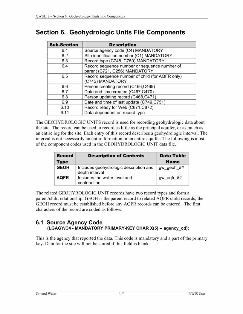
CHAPTER 2, SECTION 6 GEOHYDROLOGIC UNITS FILE COMPONENTS ....... 105
6.1 SOURCE AGENCY CODE ........................................................................................ 105 6.2 SITE IDENTIFICATION NUMBER ............................................................................. 106 6.3 RECORD TYPE....................................................................................................... 106 6.4 RECORD SEQUENCE NUMBER OR SEQUENCE NUMBER OF PARENT ....................... 106 6.5 RECORD SEQUENCE NUMBER OF CHILD ............................................................... 106 6.6 PERSON CREATING RECORD ................................................................................. 107 6.7 DATE AND TIME CREATED.................................................................................... 107 6.8 PERSON UPDATING RECORD ................................................................................. 107 6.9 DATE AND TIME OF LAST UPDATE........................................................................ 107 6.10 RECORD READY FOR WEB .................................................................................. 108 6.11 DATA DEPENDENT ON RECORD TYPE................................................................. 108
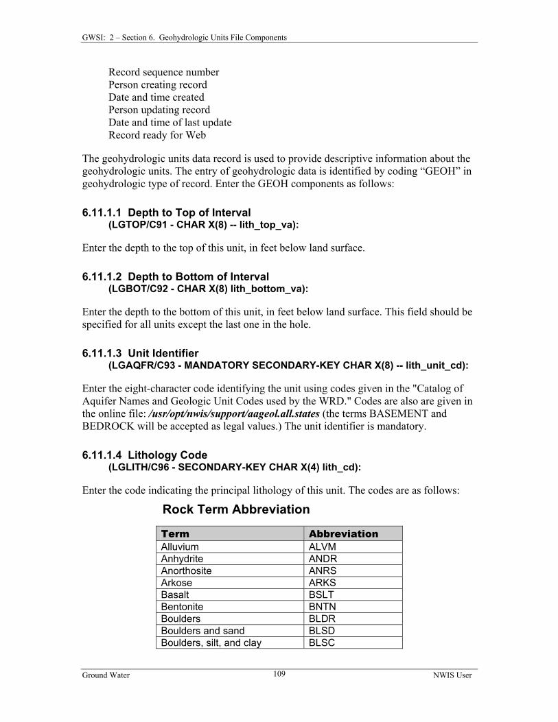
6.11.1 Geohydrologic Units Record ..................................................................... 108 6.11.1.1 Depth to Top of Interval ...................................................................... 109 6.11.1.2 Depth to Bottom of Interval................................................................. 109 6.11.1.3 Unit Identifier....................................................................................... 109 6.11.1.4 Lithology Code .................................................................................... 109 6.11.1.5 Contributing Unit ................................................................................. 111 6.11.1.6 Lithologic Modifier.............................................................................. 112
6.11.2 Aquifers Record ......................................................................................... 112 6.11.2.1 Aquifer Date......................................................................................... 113 6.11.2.2 Static Water Level................................................................................ 113 6.11.2.3 Percent Water Contributed................................................................... 113
Ground Water NWIS User vii
Table of Contents
CHAPTER 2, SECTION 7 OBSERVATION WELL HEADING FILE COMPONENTS............................................................................................................ 114
7.1 SOURCE AGENCY CODE.................................................................................. 114 7.2 SITE IDENTIFICATION NUMBER ............................................................................. 114 7.3 RECORD SEQUENCE NUMBER ............................................................................... 114 7.4 PERSON CREATING RECORD ................................................................................. 114 7.5 DATE AND TIME CREATED.................................................................................... 115 7.6 PERSON UPDATING RECORD ................................................................................. 115 7.7 DATE AND TIME OF LAST UPDATE........................................................................ 115 7.8 RECORD READY FOR WEB .................................................................................... 115 7.9 OBSERVATION WELL HEADING LINE.................................................................... 115
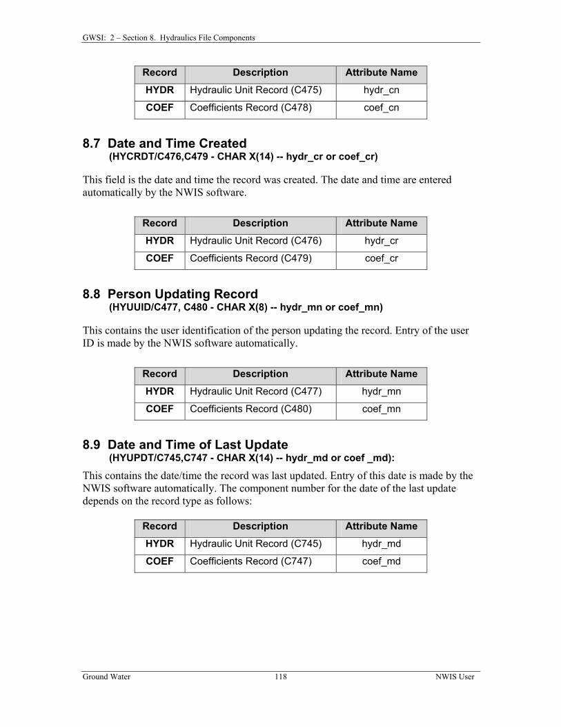
CHAPTER 2, SECTION 8 HYDRAULICS FILE COMPONENTS ...................... 116 8.1 SOURCE AGENCY CODE ........................................................................................ 116 8.2 SITE IDENTIFICATION NUMBER ............................................................................. 116 8.3 RECORD TYPE....................................................................................................... 117 8.4 RECORD SEQUENCE NUMBER OR SEQUENCE NUMBER OF PARENT ....................... 117 8.5 RECORD SEQUENCE NUMBER OF CHILD ............................................................... 117 8.6 PERSON CREATING RECORD ................................................................................. 117 8.7 DATE AND TIME CREATED.................................................................................... 118 8.8 PERSON UPDATING RECORD ................................................................................. 118 8.9 DATE AND TIME OF LAST UPDATE........................................................................ 118 8.10 RECORD READY FOR WEB FLAG......................................................................... 119 8.11 DATA DEPENDENT ON RECORD TYPE................................................................. 119
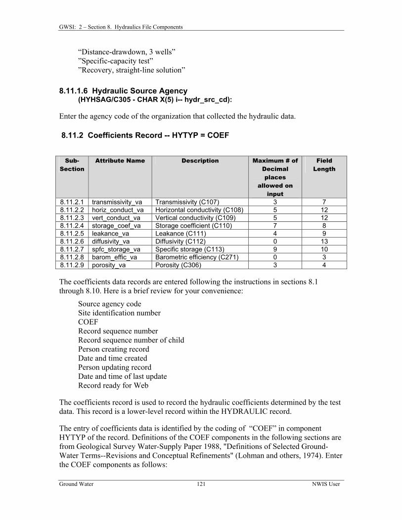
8.11.1 Hydraulic Records ..................................................................................... 119 8.11.1.1 Hydraulic Unit ..................................................................................... 120 8.11.1.2 Depth to Top of Interval ...................................................................... 120 8.11.1.3 Depth to Bottom of Interval................................................................. 120 8.11.1.4 Hydraulic Unit Type ............................................................................ 120 8.11.1.5 Hydraulic Remarks .............................................................................. 120 8.11.1.6 Hydraulic Source Agency .................................................................... 121
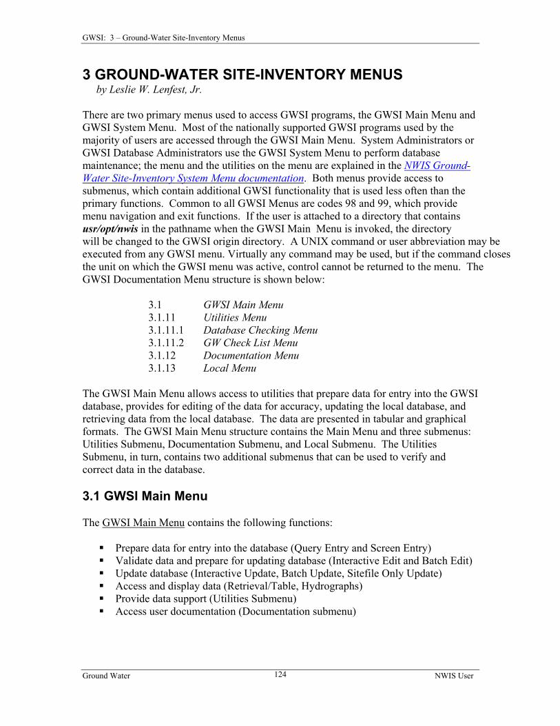
3.1 GWSI MAIN MENU ............................................................................................... 124 3.1.1 Option 1: Query Entry ................................................................................... 125 3.1.2 Option 2: Screen Entry................................................................................... 125
Ground Water NWIS User viii
Table of Contents
3.1.3 Option 3: Edit GW Data/Option 13: Edit GW Data in Batch........................ 125 3.1.4 Option 4: Update GW Data/Option 14: Update GW Data in Batch .............. 126 3.1.5 Option 5: Update Sitefile Only ...................................................................... 126 3.1.6 Option 6: Retrieval/Tables............................................................................. 126 3.1.7 Option 7: Copy File (from 1-2) to Directory Watin ...................................... 126 3.1.8 Option 10: Change GW/QW Database Number............................................ 126 3.1.9 Option 11: Generate Field Forms .................................................................. 126 3.1.10 Option 16: Plot Hydrographs ....................................................................... 126 3.1.11 Option 91: The Utilities Submenu ............................................................... 127
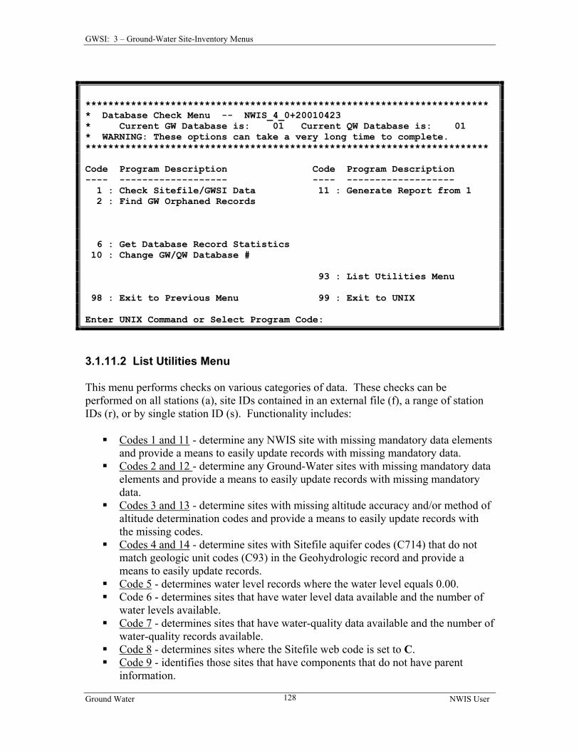
3.1.11.1 Database Checking Menu ..................................................................... 127 3.1.11.2 List Utilities Menu ................................................................................ 128
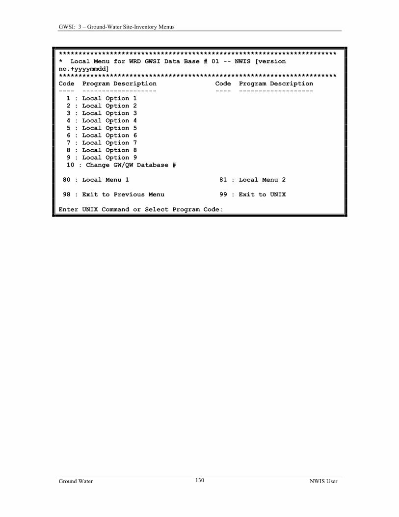
3.1.12 Documentation Submenu............................................................................. 129 3.1.13 Local Menu .................................................................................................. 129
4.3.1 Using a prompt list file ................................................................................. 132 4.3.1.1 Creating a prompt list file ....................................................................... 132 4.3.1.2 Using an existing prompt list file............................................................ 134
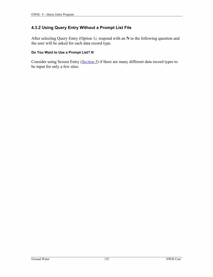
4.3.2 Using Query Entry (gwinput) Without a Prompt List File ............................ 135 CHAPTER 5 SCREEN ENTRY PROGRAM............................................................ 136
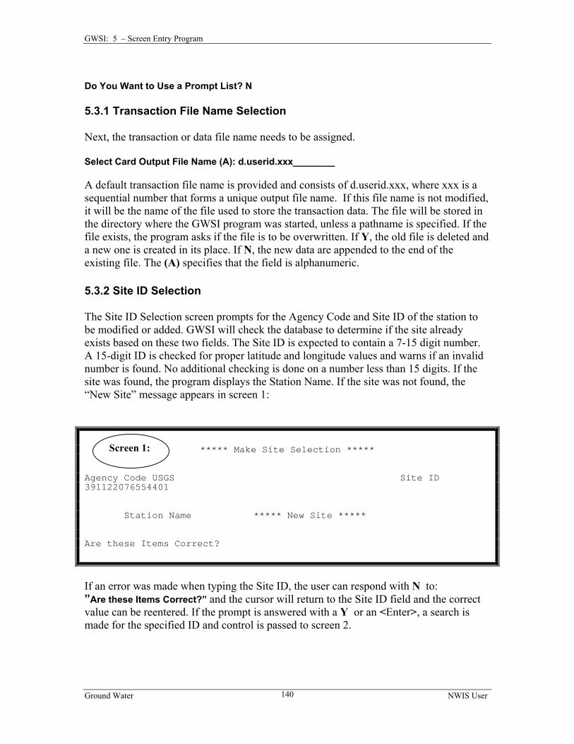
5.3.1 Transaction File Name Selection ................................................................... 140 5.3.2 Site ID Selection ............................................................................................ 140 5.3.3 General Site Data ........................................................................................... 141 5.3.4 Data Entry Screens........................................................................................ 142
5.3.4.1 Program Option Screens ........................................................................ 142 5.3.4.2 Record Selection Screens....................................................................... 143 5.3.4.3 Record Data Entry Screens .................................................................... 143
5.3.5 Required Fields .............................................................................................. 144 5.3.6 Error-Checking ............................................................................................. 145 5.3.7 Default Data .................................................................................................. 145 5.3.8 Data Field Justification ................................................................................. 145 5.3.9 Using Prompt List Files ................................................................................. 145
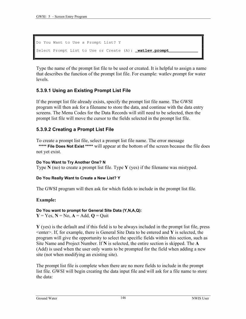
5.3.9.1 Using an Existing Prompt List File......................................................... 146 5.3.9.2 Creating a Prompt List File..................................................................... 146
5.4 TRANSACTION DATA OUTPUT FILE……………………………………………….147
CHAPTER 6 GROUND-WATER EDIT PROGRAM……………………………...148 6.1 INTRODUCTION…………………………………………………….…………..….148 6.2 PROGRAM OPERATION……………………………………………………………148 6.3 FILES USED BY THE GROUND-WATER EDIT PROGRAM…….……………………..148
8.1 INTRODUCTION………………………………………………….………….……..161 8.2 OPERATION OF RETRIEVAL SOFTWARE……………………………………………161
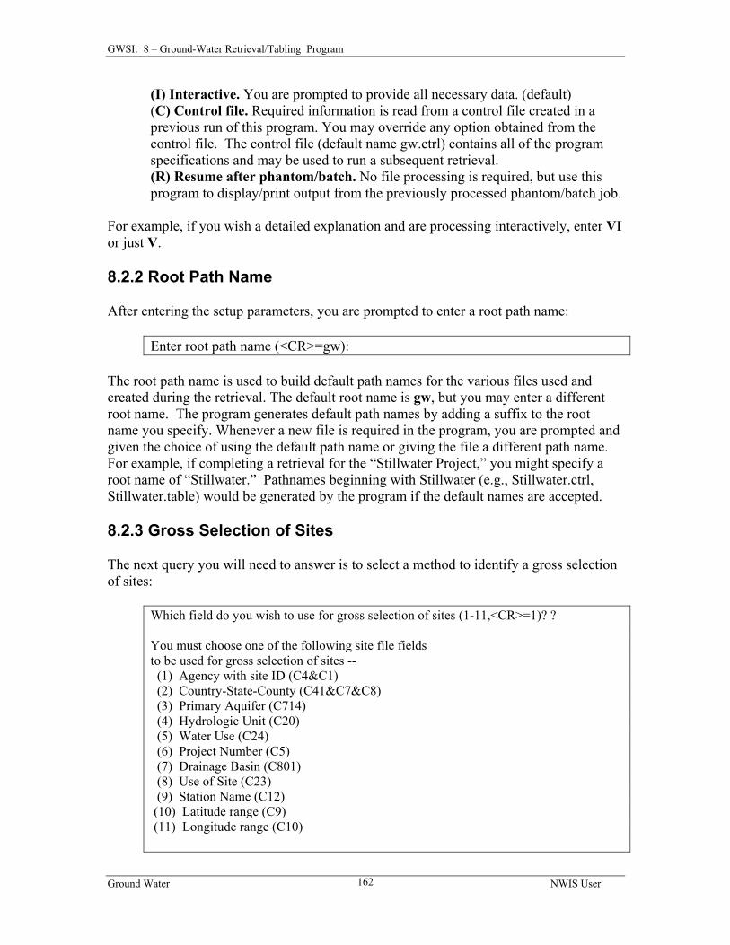
8.2.1 Set-Up Parameters..…..…………..……………………………….…………161 8.2.2 Root Path Name..……..………………………………………………….….162 8.2.3 Gross Selection of Sites……………………………………………….…….162 8.2.4 Limitation for Site Selection………….……………………………………….163
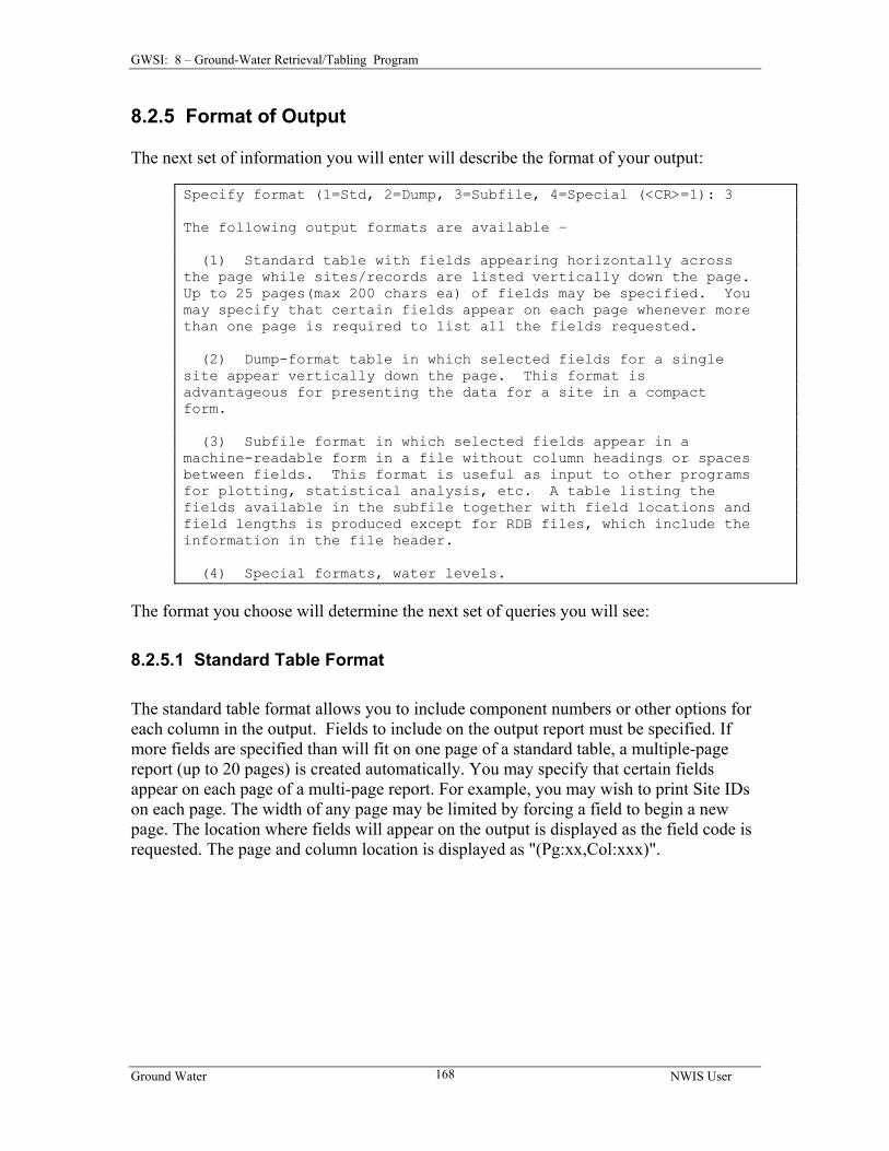
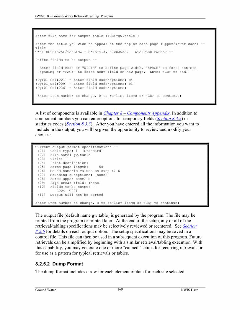
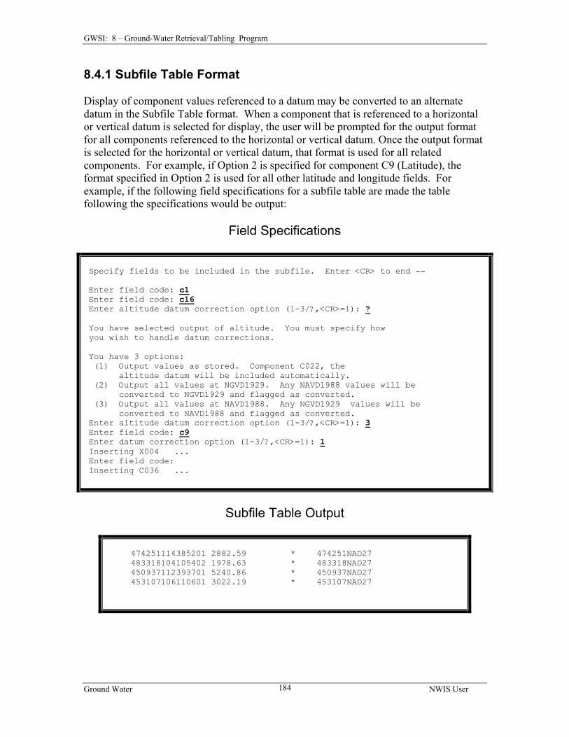
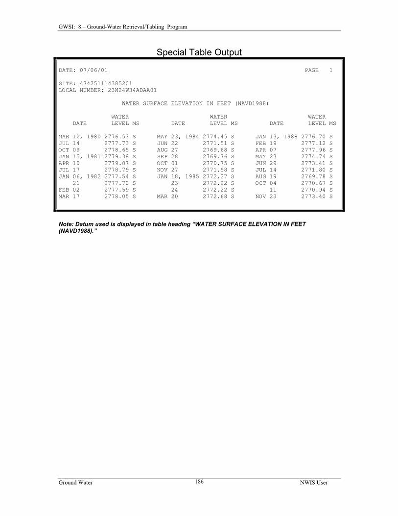
8.2.5 Format of Output……………………………………………………………168 8.2.5.1 Standard Table Format………………………………………………….168 8.2.5.2 Dump Format……………………………………………………………169 8.2.5.3 Subfile Format…………………………………………………………..171 8.2.5.4 Special Table Format – Water Levels…………………………………..172 8.2.6 Output Options………………………………………………………………174 8.2.7 Processing Parameters………………………………………………………176
CHAPTER 10 GENERATE FIELD FORMS……………………………………….216
10.1 INTRODUCTION……………………………………………….………….……....216 10.2 PROGRAM OPERATION…………………………………………………………..216
10.2.1 Selection of Field Form Name..……………………………………………217 10.2.1.1 Field Form File Already Exists…………………………………..……217
Ground Water NWIS User x
Table of Contents
10.2.1.2 Field Form File Does Not Exist…………………………………..……217 10.2.2 Output a Field Form……….…….…………………………………….…….218
10.2.2.1 Specifying File Containing Site IDs……………………………..……218 10.2.2.2 Specifying Site IDs Without a File………………………..……..……218
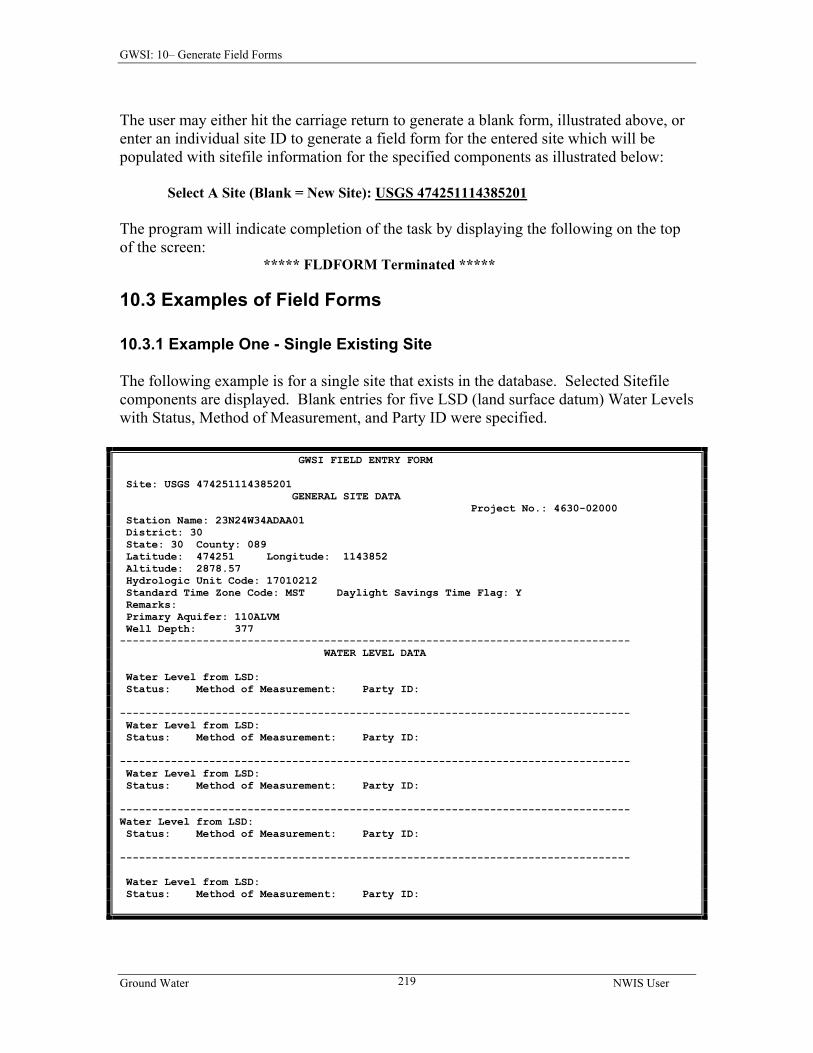
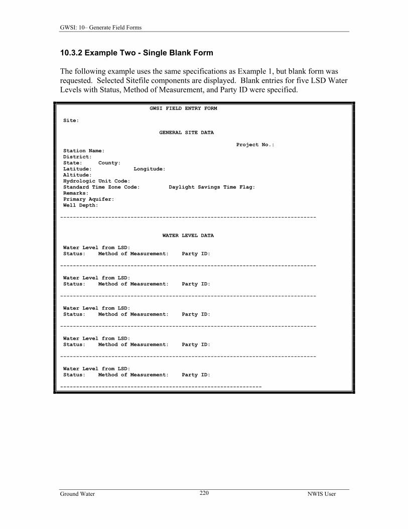
10.3 EXAMPLES OF FIELD FORMS………………………….….…………….………...219 10.3.1 Example One – Single Existing Site…………………………………………219 10.3.2 Example Two – Single Blank Form.. ………………………………..………220
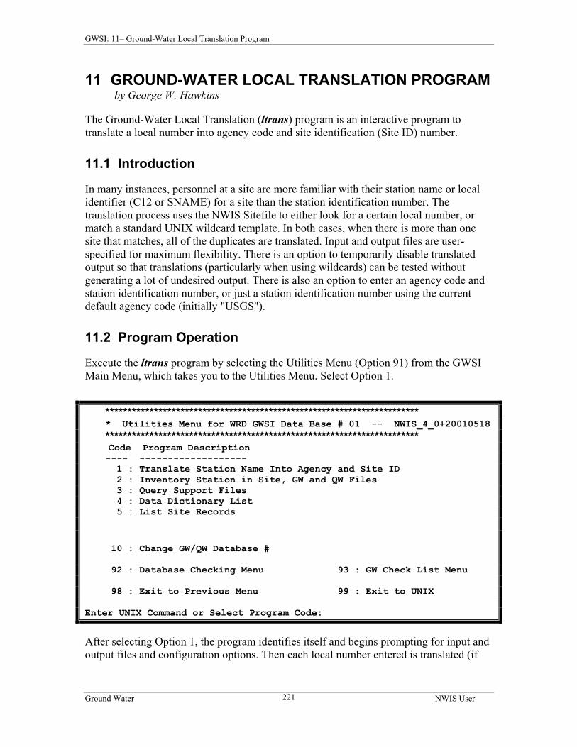
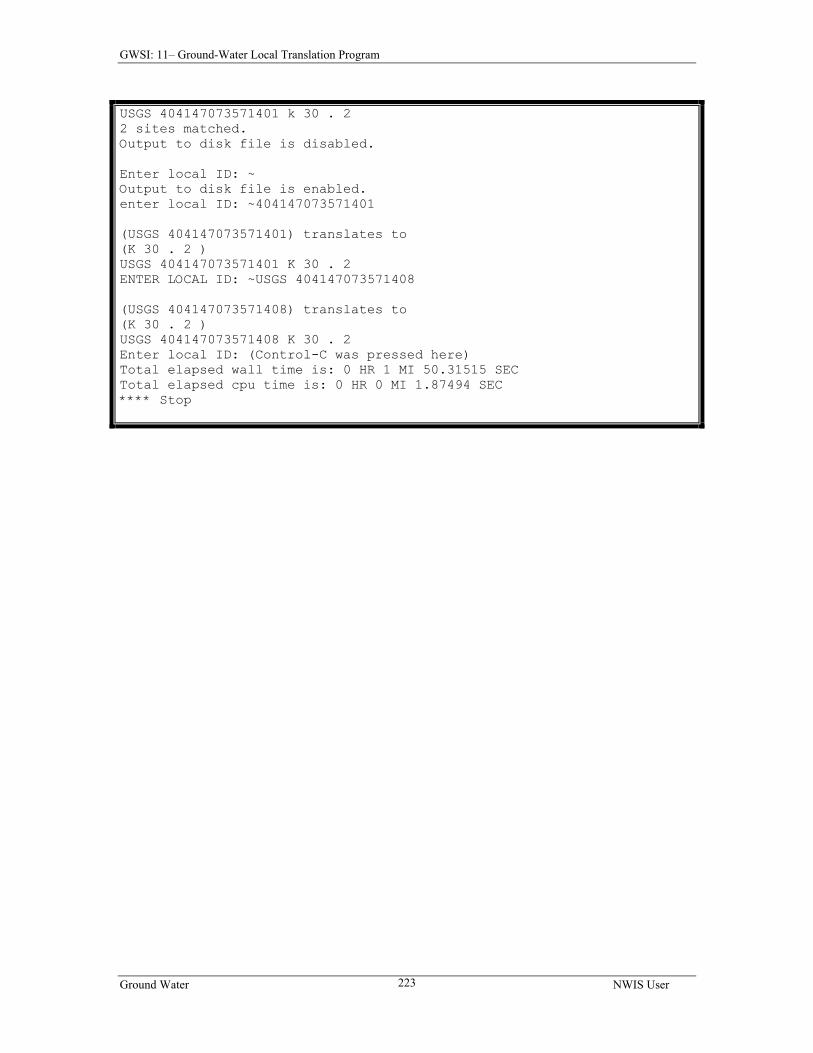
CHAPTER 11 GROUND-WATER LOCAL TRANSLATION PROGRAM..…….221 11.1 INTRODUCTION……………………………………………….………….……....221 11.2 PROGRAM OPERATION……………………………………………….…………..221
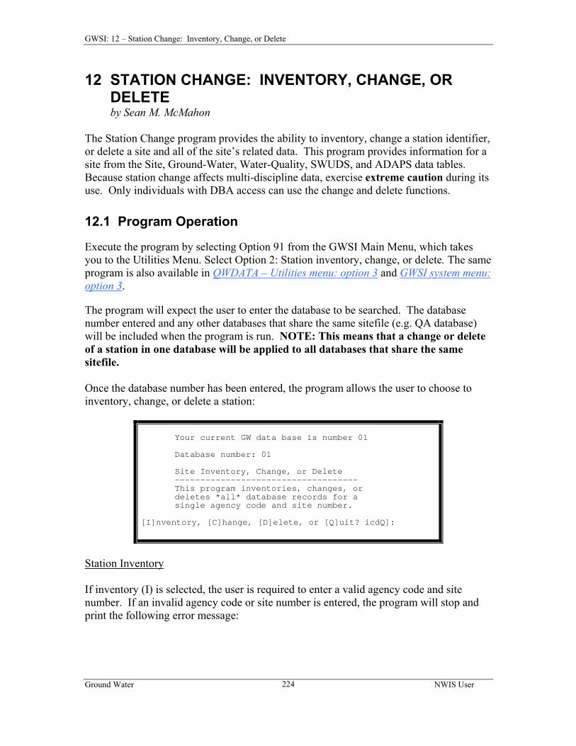
CHAPTER 12 STATION CHANGE: INVENTORY, CHANGE, OR DELETE…………………..……………………….….…….......…….….……….....224
12.1 PROGRAM OPERATION……………………………………….………….……....224
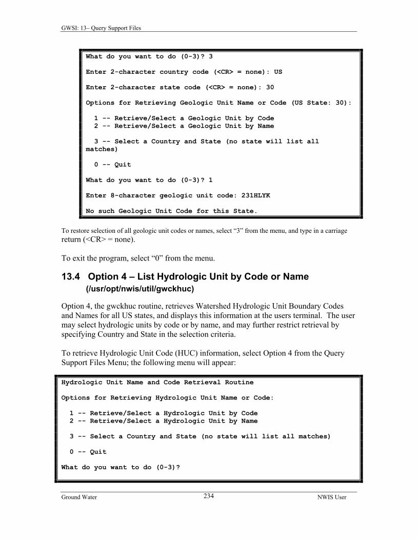
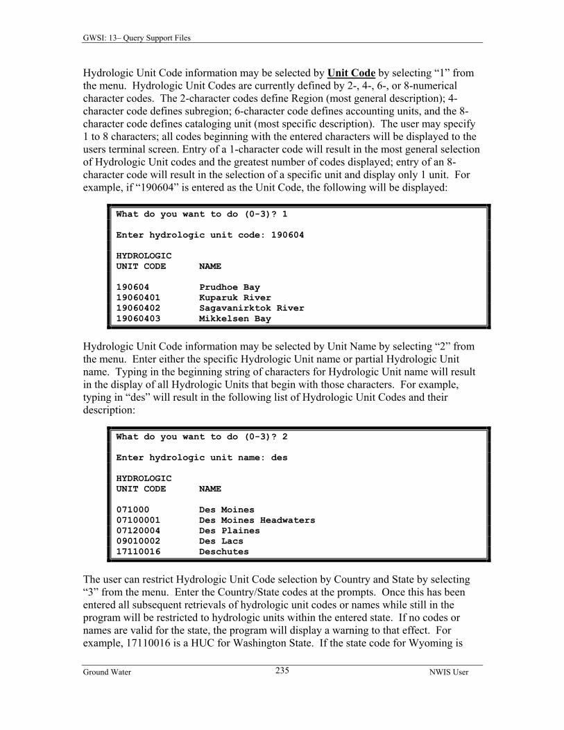
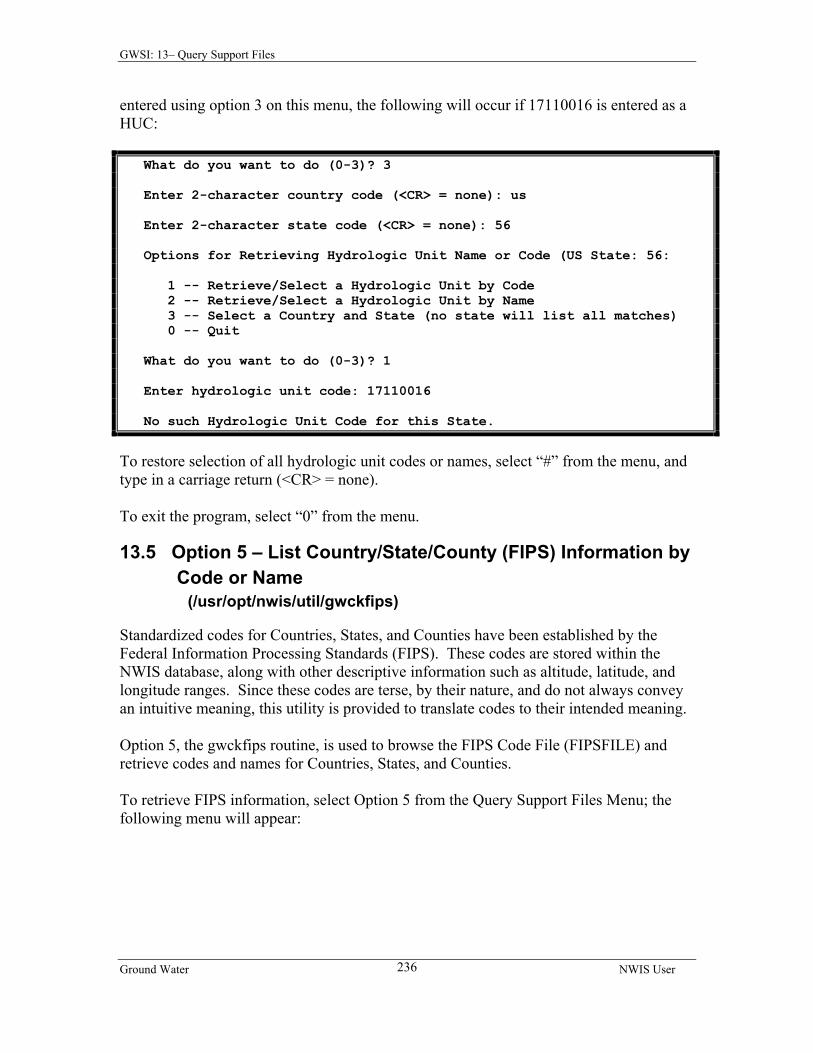
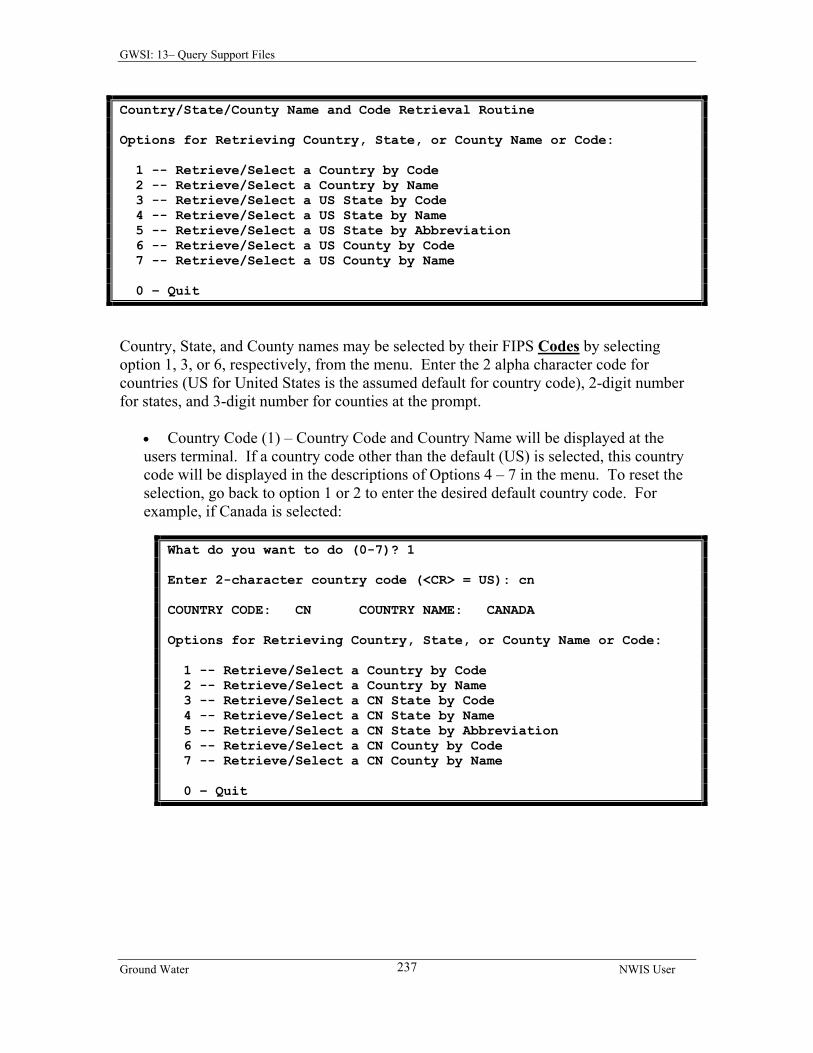
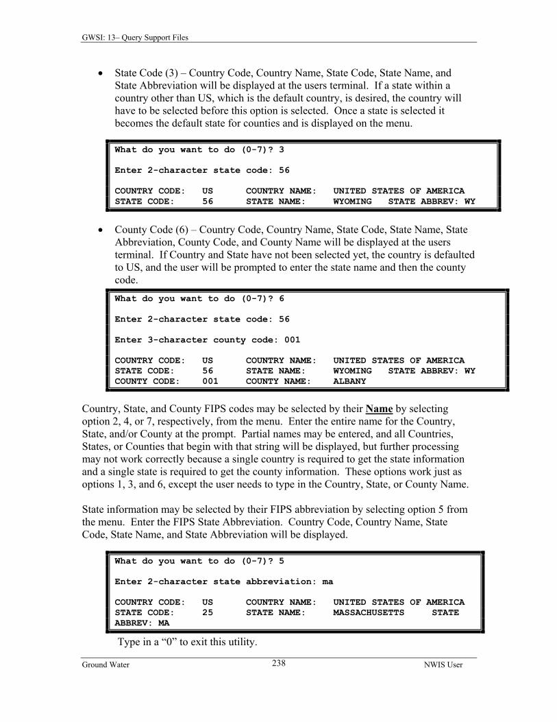
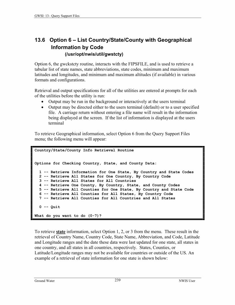
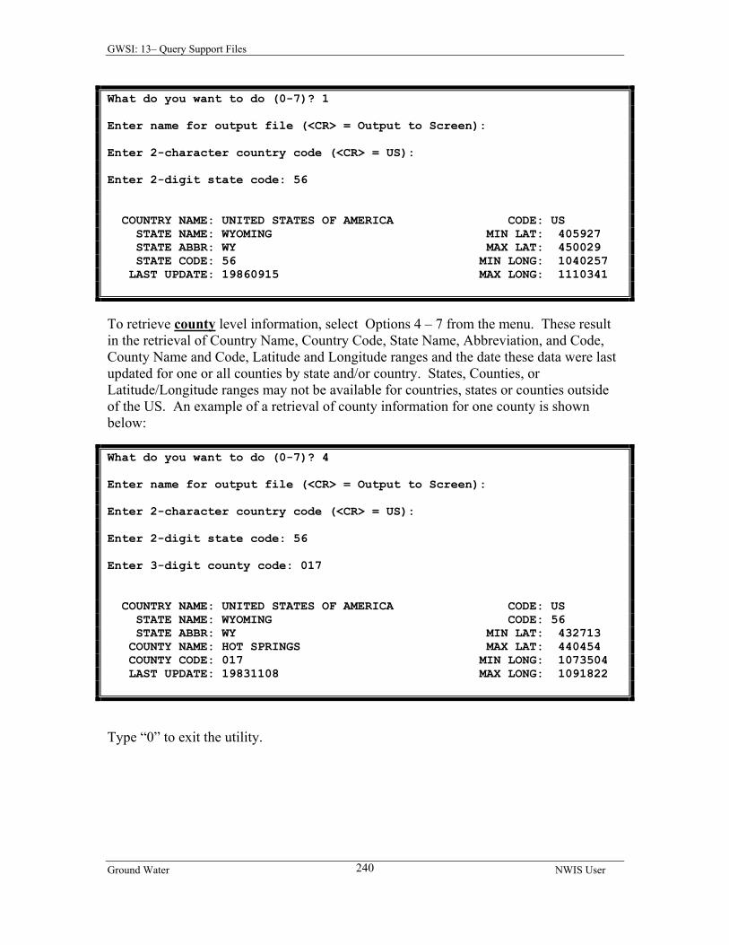
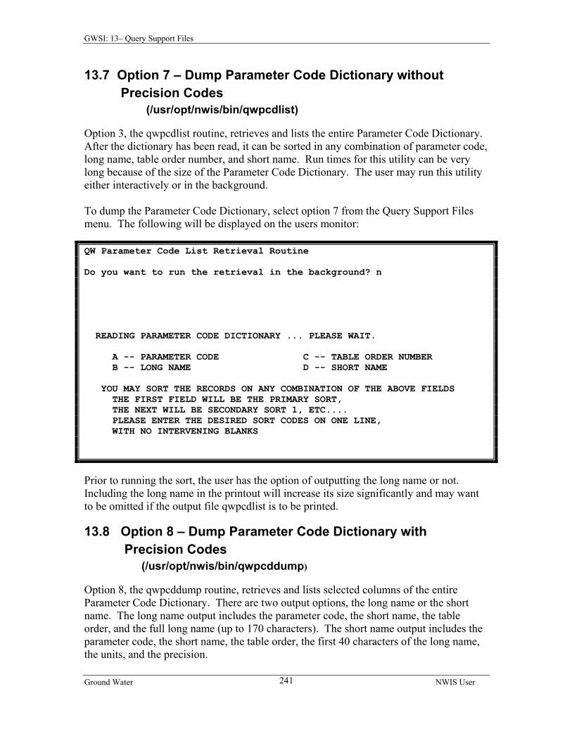
CHAPTER 13 QUERY SUPPORT FILES………………………………….……….230 13.1 OPTION 1 – LIST SITE RECORDS…………..………………….………….……....230 13.2 OPTION 2 – LIST PARAMETER BY NAME OR CODE ..…..………………………..231 13.3 OPTION 3 – LIST GEOLOGIC UNIT BY CODE OR NAME……….………………....232 13.4 OPTION 4 – LIST HYDROLOGIC UNIT BY CODE OR NAME…..…………….…….234 13.5 OPTION 5 – LIST COUNTRY/STATE/COUNTY (FIPS) INFO BY CODE OR NAME....236 13.6 OPTION 6 – LIST COUNTRY/STATE/COUNTY W/GEOGRAPHICAL INFO……...…..239 13.7 OPTION 7 – LIST PARAMETER CODE DICTIONARY WITHOUT PRECISION CODES..241 13.8 OPTION 8 – DUMP PARAMETER CODE DICTIONARY WITH PRECISION CODES…..241
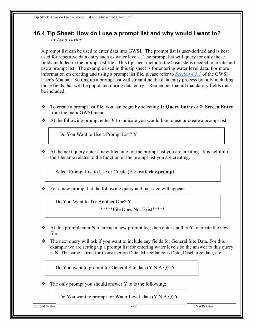
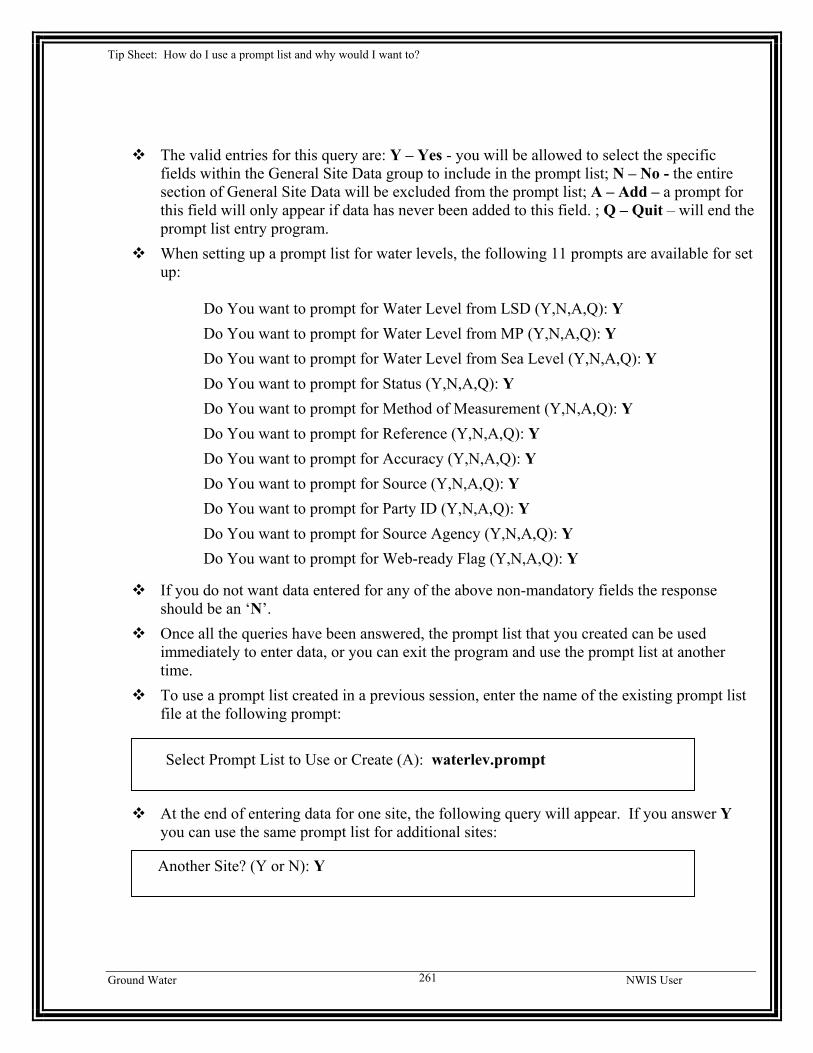
CHAPTER 16 TIP SHEETS……….………………………………………..….…….249 16.1 INPUT WATER LEVELS – QUERY ENTRY............................................................. 249 16.2 INPUT WATER LEVELS – SCREEN ENTRY............................................................ 253 16.3 PROBLEM-REPORTING SYSTEM - GNATS ......................................................... 257 16.4 PROMPT LIST ...................................................................................................... 260
Ground Water NWIS User xi
GWSI: 1 – Introduction
USER’S MANUAL FOR THE NATIONAL WATER INFORMATION SYSTEM OF THE
U.S. GEOLOGICAL SURVEY
GROUND-WATER SITE-INVENTORY SYSTEM
Open-File Report 2004-1238 Version 4.3
ABSTRACT
The Ground-Water Site-Inventory (GWSI) System is a ground-water data storage and retrieval system that is part of the National Water Information System (NWIS) developed by the U.S. Geological Survey (USGS). The NWIS is a distributed water database in which data can be processed over a network of workstations and file servers at USGS offices throughout the United States. This system comprises the GWSI, the Automated Data Processing System (ADAPS), the Water-Quality System (QWDATA), and the Site-Specific Water-Use Data System (SWUDS). The GWSI System provides for entering new sites and updating existing sites within the local database. In addition, the GWSI provides for retrieving and displaying ground-water and sitefile data stored in the local database. Finally, the GWSI provides for routine maintenance of the local and national data records. This manual contains instructions for users of the GWSI and discusses the general operating procedures for the programs found within the GWSI Main Menu.
1 INTRODUCTION by Leslie W. Lenfest, Jr. This section is an introduction to the GWSI User's Manual. It presents a management overview, description of the GWSI System, purpose of the manual, an acknowledgement of personnel who contributed to the completion of this manual, and a list of selected references.
1.1 Management Overview The USGS investigates the occurrence, quantity, quality, distribution, and movement of the surface- and ground-water resources of the Nation. Hydrologic data collected during investigations of these resources provide valuable information that can be used for practical management of America's water. Easy access to hydrologic data facilitates the management process.
GWSI NWIS User
1
GWSI: 1 – Introduction The GWSI is part of the NWIS, which is a data storage and retrieval system for hydrologic data collected by the USGS and its cooperators. The ADAPS, QWDATA System, and SWUDS comprise the other parts of the NWIS.
1.2 Description of the GWSI The storage of ground-water data has evolved over several decades, from hand-written field notes stored in file cabinets at the State office level, to a distributed database where data can be processed over a network of UNIX workstations and file servers at USGS offices throughout the United States. Digital storage of data has developed from a punch-card data system in the late 1960’s, to a national database in the mid 1970’s, to a distributed database in the mid 1980’s, and presently to an Ingres-based database where data are stored as tables. Much of the data are served to a Web-based national database (NWISWeb). The present system is a conversion of the distributed database on the Prime minicomputers to UNIX-based workstations and file servers located in USGS offices nationwide. Turnaround time for data storage and retrieval procedures has improved during this period from several days to minutes. Currently, the GWSI is an interactive system, located on USGS workstations and file servers that maintains a dialog with the users through menus and prompts. The GWSI provides a method to enter new sites and update existing sites within the database. The GWSI also provides a method to retrieve and display, in several useful formats, ground-water and sitefile data that are stored in the local database. Finally, the GWSI provides for routine maintenance of the local and national data records. The GWSI contains descriptive elements about sites where information is accessed from wells, test holes, springs, tunnels, drains, ponds or other excavations. There are over 500 components that make up the descriptive elements of the GWSI. These components are stored in a general data file called the “sitefile,” which contains site information common to all members of NWIS, and in over 25 data tables that contain ground-water-related information. The sitefile primarily contains location information, physical and political descriptors, and data-collection methods used at the sites. The data tables contain well-construction, ground-water level, ground-water discharge, miscellaneous, geohydrologic, observation-well heading, and hydraulic data. Ground-water data manipulations are initiated through GWSI utilities accessed through the GWSI Main Menu and submenus. The GWSI Main Menu is accessed by typing the system command "gwsi" at the user's terminal. This command displays the menu shown in the Ground-Water Site Inventory Main Menu, discussed in Chapter 3. The GWSI System provides two programs, Query Entry and Screen Entry, for entering field data into files used to update the local database. Files created by the entry programs are reviewed and validated by the Ground-Water Edit program to ensure that entered data conform to expected criteria. Once the data pass the Edit program, they are entered into the databases using the Ground-Water Update program. Data may be retrieved from the
GWSI NWIS User
2
GWSI: 1 – Introduction local database through the Ground-Water Retrieval/Tabling program and displayed in graphical form using the Ground-Water Hydrograph program. The GWSI System Menu is used to provide maintenance of the database and for other GWSI administrative tasks. Data Dictionary modifications and Site ID changes and deletes are other options on the GWSI System Menu.
1.3 Purpose of the Manual The purpose of this User’s Manual is to document the operating modules of the GWSI and provide additional operating instructions to the user. The GWSI User’s Manual describes the primary user functions found in the GWSI Main Menu and submenus:
Section Description 1 Abstract and Introduction 2 GWSI Coding Instructions 3 GWSI Menus 4 Query Entry Program 5 Screen Entry Program 6 Ground-Water Edit Program 7 Ground-Water Update Program 8 Ground-Water Retrieval/Tabling Program 9 Ground-Water Hydrograph Program 10 Field Forms 11 Ground-Water Local Translation Program 12 Inventory Station in GWSI and QWDATA 13 Query Support Files 14 Change Default Database Number 15 Error Messages
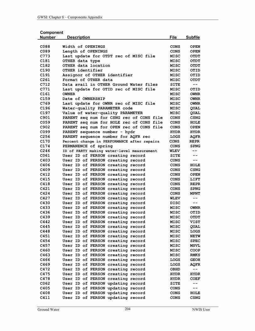
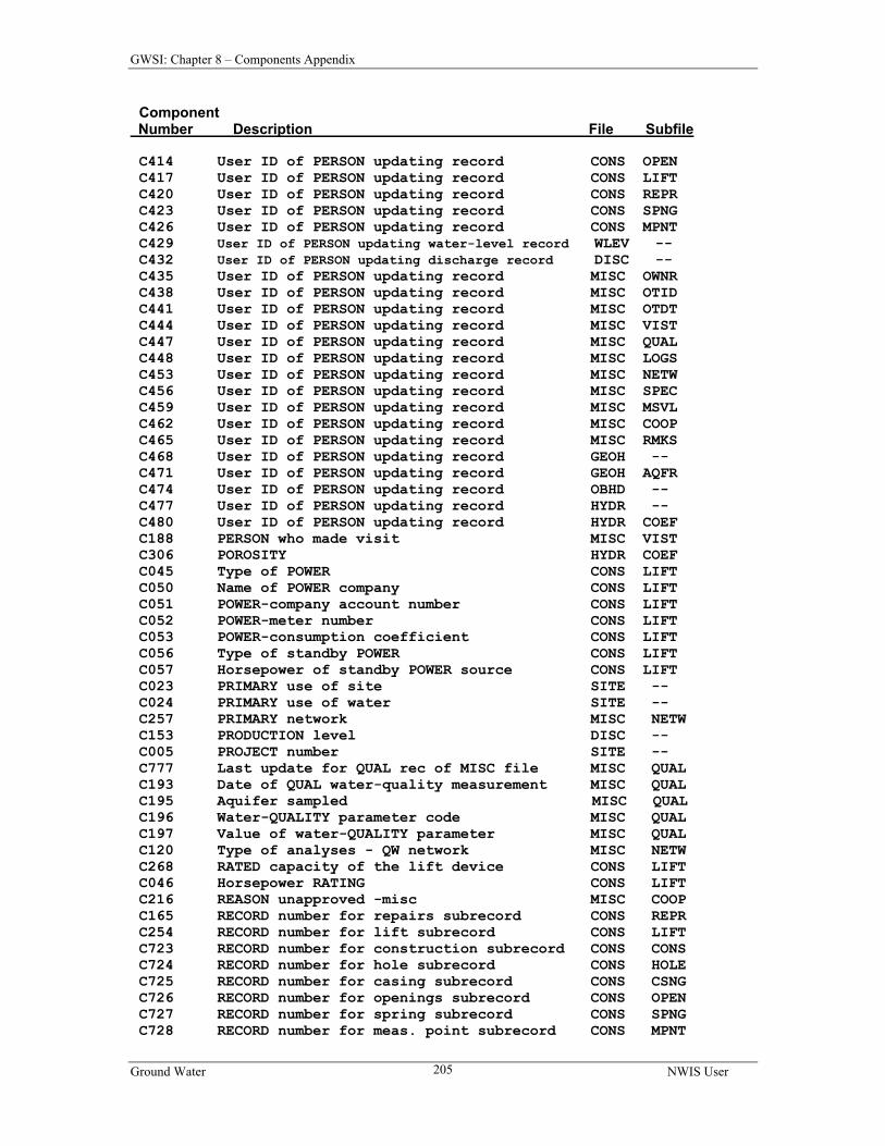
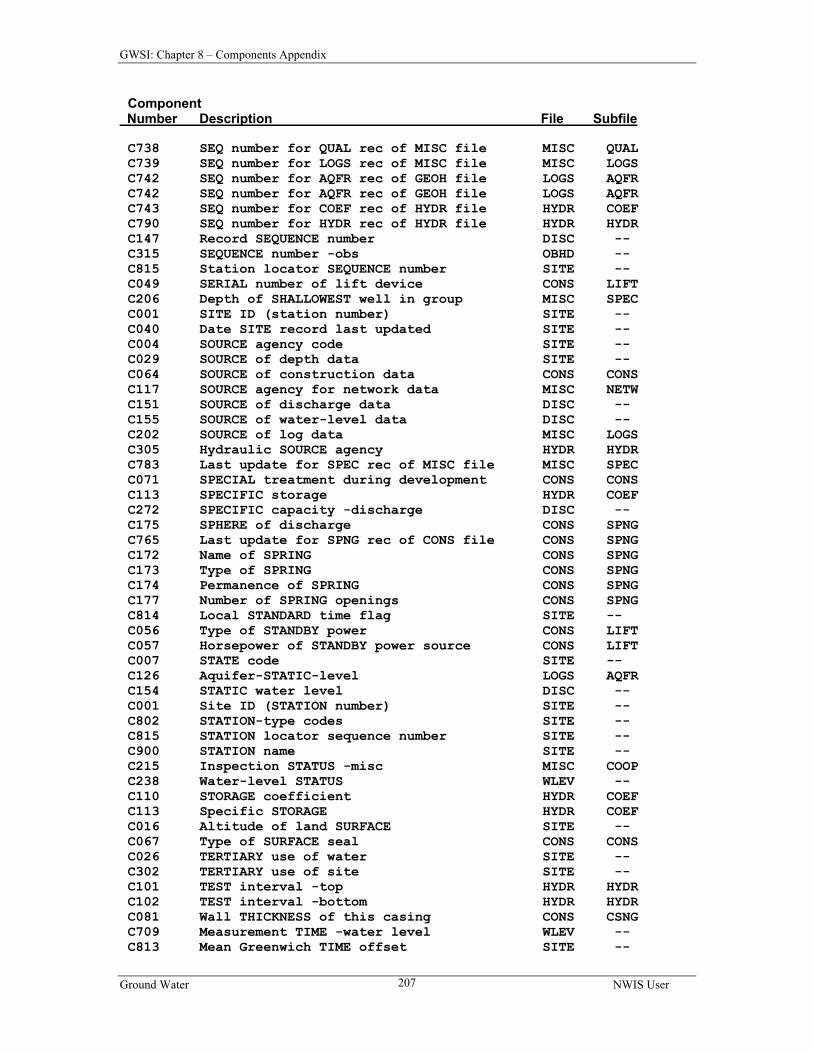
The GWSI Coding Instructions (Chapter 2 of this manual) describe every data component contained in the sitefile and ground-water data records. Component descriptions consist of the component name, component number, the format of the entry, and a brief explanation of what the component is and how it is entered. Mandatory components are identified. Several components are limited in response to a list of acceptable names or terms; acceptable responses are tabulated in the manual for those components. The GWSI Menus (Chapter 3) and their elements are described. Most of the nationally supported GWSI software that is used to submit and retrieve data is accessed from the Main Menu. Currently, there are 12 data entry and retrieval selections on the GWSI Main Menu, two submenus (Utilities and Documentation), access to a specified Local Menu, and two exit modes from the Main Menu. The Utilities submenu contains access to six data utility programs, two database maintenance menus, and two exit modes. The Documentation submenu now opens in a separate browser window.
GWSI NWIS User
3
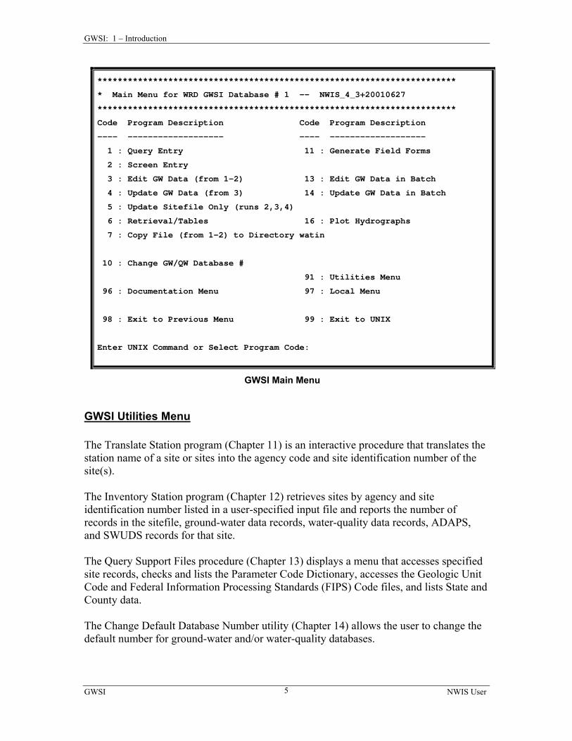
GWSI: 1 – Introduction GWSI Main Menu The Query Entry program (Chapter 4) is the first of two modules in the GWSI Main Menu used to prepare sitefile and ground-water data for editing and updating. Although both modules create card images in user-specified records that ultimately are used for updating local and national databases, neither module directly updates databases. The Query Entry program is an interactive program that prompts the user with a defined list of GWSI components. It stores user responses along with the required component numbers, delimiters, and other program-generated elements used by the Edit program in a user-specified output file. The Screen Entry program (Chapter 5) is the second module used to prepare data for editing and updating. Screen Entry input displays a “form” to be filled in by the user. It stores user responses along with the required component numbers, delimiters, and other program-generated elements in a user-specified output file. The Edit program (Chapter 6) performs edit validation and logical data checks on the output files created by the Query Entry and Screen Entry programs. Edit checks may be initiated for interactive processing or batch processing. Both processing modes are discussed in Chapter 6. The Update program (Chapter 7) is used to update the NWIS sitefile and the GWSI data records in the database after the data records have successfully passed the Edit GWSI Data program. This program is also available in either interactive or batch modes. The Retrieval/Tabling program (Chapter 8) provides access to the data stored in the database. Retrieved data may be obtained in several formats: two types of general data tables, four types of water-level tables, and as a data record that can be used as input into other programs. A list of all component numbers and their descriptions is included in this section. The Plot Hydrographs program (Chapter 9) provides graphical representation of ground-water levels. Data are retrieved using the Retrieval/Tabling program and displayed on the user’s monitor or at a designated printer using TKG2 graphics. The Field Forms program (Chapter 10) generates a form that can be used in the field to collect data. The form contains user-specified components, and in some instances, may be pre-populated with data from the database that are helpful in determining the location of the site and in collecting the data.
3 : Edit GW Data (from 1-2) 13 : Edit GW Data in Batch
4 : Update GW Data (from 3) 14 : Update GW Data in Batch
5 : Update Sitefile Only (runs 2,3,4)
6 : Retrieval/Tables 16 : Plot Hydrographs
7 : Copy File (from 1-2) to Directory watin
10 : Change GW/QW Database #
91 : Utilities Menu
96 : Documentation Menu 97 : Local Menu
98 : Exit to Previous Menu 99 : Exit to UNIX
Enter UNIX Command or Select Program Code:
GWSI Main Menu
GWSI Utilities Menu The Translate Station program (Chapter 11) is an interactive procedure that translates the station name of a site or sites into the agency code and site identification number of the site(s). The Inventory Station program (Chapter 12) retrieves sites by agency and site identification number listed in a user-specified input file and reports the number of records in the sitefile, ground-water data records, water-quality data records, ADAPS, and SWUDS records for that site. The Query Support Files procedure (Chapter 13) displays a menu that accesses specified site records, checks and lists the Parameter Code Dictionary, accesses the Geologic Unit Code and Federal Information Processing Standards (FIPS) Code files, and lists State and County data. The Change Default Database Number utility (Chapter 14) allows the user to change the default number for ground-water and/or water-quality databases.
GWSI NWIS User
5
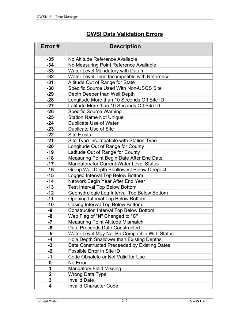
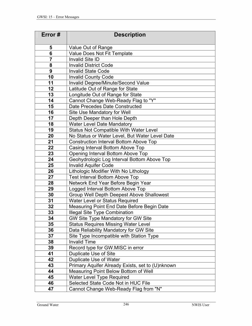
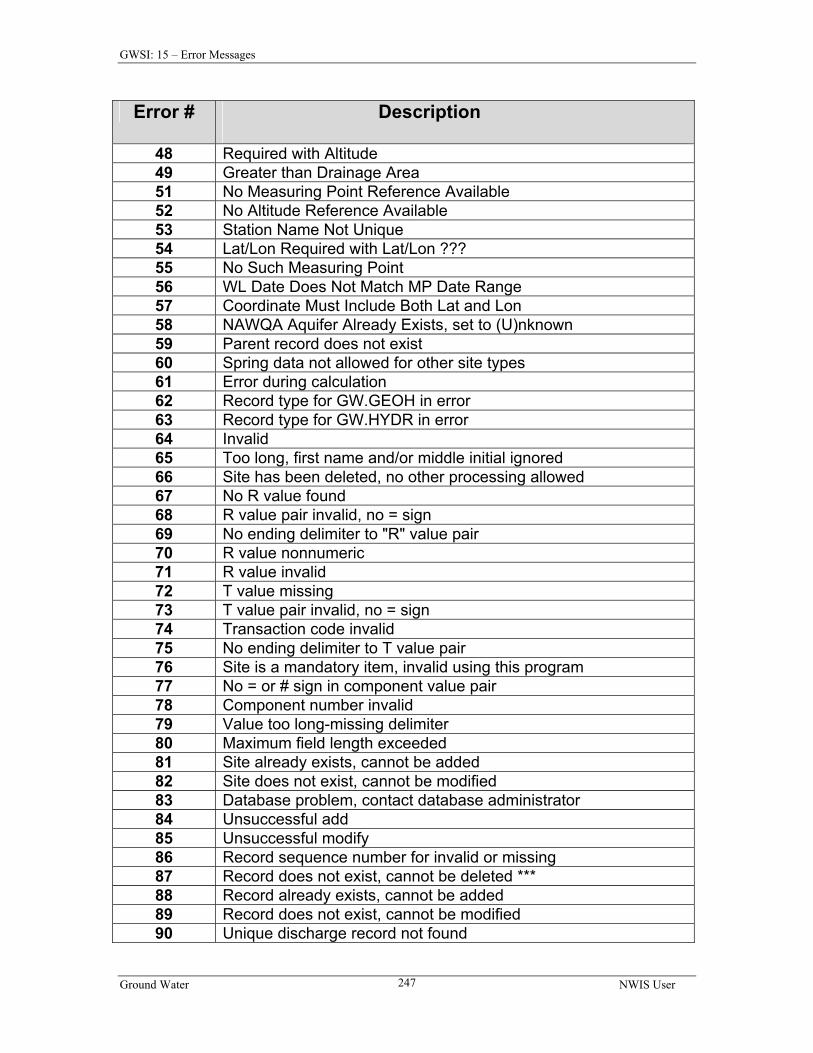
GWSI: 1 – Introduction Error messages (Chapter 15) list the code number and description of all error messages that can occur during the Edit and Update procedures. The user is led through the basic modules by a series of prompts and questions. In many instances, help is provided when a question mark (?) is typed in response to a prompt that is not understood. Additional documentation is available from the User’s Manual or documentation files contained within the GWSI system.
1.4 Acknowledgements Acknowledgement is given to current and past contributors of the development and maintenance of the GWSI software. The current software is maintained by John Atwood.
In addition to the authors of the programs within the GWSI System, acknowledgment is given to several people who contributed by testing software, and preparing and reviewing documentation. These personnel include:
Nancy L. Barber Ron Lane Pamilee L. Breton Wayne Lapham Tony Brown Wendell L. Lovelace Jilann Brunett Jayne E. May Alan W. Burns Keith L. McFadden Annette Campbell Rodney A. Sheets David A. Cohen Roy Sonenshein Charles A. Collins Pat Strelakos Linda Geiger Sonya Vaquez Gail L. Keeter
1.5 Selected References Baker, C.H., Jr., and Foulk, D.G., 1975, WATSTORE user's guide, v. 2, ground-water
file: U.S. Geological Survey Open-File Report 75-589.
Hantush, M.S., 1964, Hydraulics of wells, in Chow, Ven Te, ed., Advances in Hydroscience, v. 1: New York, Academic Press, Inc., p. 281-442.
Lohman, S.W., and others, 1972, Definitions of selected ground-water terms--revisions and conceptual refinements: U.S. Geological Survey Water-Supply Paper 1988, 21 p.
Luckey, R.R., 1987, The distributed ground-water database of the U.S. Geological Survey, in James, Larry G., and English, Marshall J., eds., Irrigation systems of the 21st century: American Society of Civil Engineers Irrigation and Drainage Division Specialty Conference, Portland, Oregon, July 28-30, 1987, proceedings, p. 263-269.
Todd, D.K., 1980, Groundwater Hydrology: New York, John Wiley & Sons, p. 535.
by Colleen Babcock, Richard R. Luckey, Charles O. Morgan and Diane M. Stephens Revised by Leslie W. Lenfest and John W. Atwood
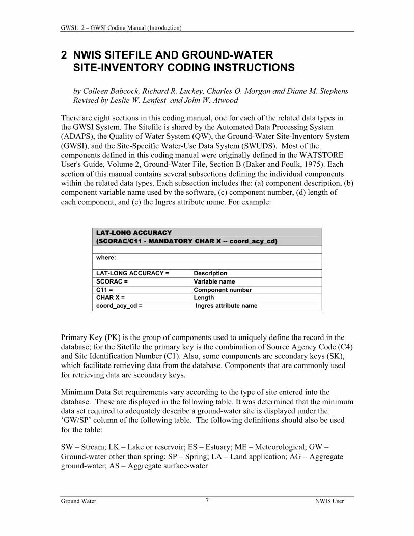
There are eight sections in this coding manual, one for each of the related data types in the GWSI System. The Sitefile is shared by the Automated Data Processing System (ADAPS), the Quality of Water System (QW), the Ground-Water Site-Inventory System (GWSI), and the Site-Specific Water-Use Data System (SWUDS). Most of the components defined in this coding manual were originally defined in the WATSTORE User's Guide, Volume 2, Ground-Water File, Section B (Baker and Foulk, 1975). Each section of this manual contains several subsections defining the individual components within the related data types. Each subsection includes the: (a) component description, (b) component variable name used by the software, (c) component number, (d) length of each component, and (e) the Ingres attribute name. For example:
LAT-LONG ACCURACY (SCORAC/C11 - MANDATORY CHAR X -- coord_acy_cd) where: LAT-LONG ACCURACY = Description SCORAC = Variable name C11 = Component number CHAR X = Length coord_acy_cd = Ingres attribute name
Primary Key (PK) is the group of components used to uniquely define the record in the database; for the Sitefile the primary key is the combination of Source Agency Code (C4) and Site Identification Number (C1). Also, some components are secondary keys (SK), which facilitate retrieving data from the database. Components that are commonly used for retrieving data are secondary keys.
Minimum Data Set requirements vary according to the type of site entered into the database. These are displayed in the following table. It was determined that the minimum data set required to adequately describe a ground-water site is displayed under the ‘GW/SP’ column of the following table. The following definitions should also be used for the table:
SW – Stream; LK – Lake or reservoir; ES – Estuary; ME – Meteorological; GW – Ground-water other than spring; SP – Spring; LA – Land application; AG – Aggregate ground-water; AS – Aggregate surface-water
Ground Water NWIS User
7
GWSI: 2 – GWSI Coding Manual (Introduction)
Mandatory for New Site Entry for Data Types:
Water Use Component Number Description
Mandatory for Web Display
SW LK ES ME
GW SP
Outfall
Diversion LA
AG AS
Place-of- Use
C004 Source Agency Code * * * * * C001 Site Identification Number * * * * * C012/C900 Station Name/Local Number * * * * * C009 Latitude * * * * C010 Longitude * * * * C011 Latitude/Longitude Accuracy * * * C035 Latitude/Longitude Method * * * C036 Latitude/Longitude Datum * * * * C006 District Code * * * * * C041 Country Code * * * * * C007 State Code * * * * * C008 County Code * * * * * C802 Station Type * * * * * C813 Time Zone Code * * * * * C814 Daylight Savings Time Flag * * * * * C003
Data Reliability
1
* C002
Site Type
1
* C023
Use of Site
1, 3
*3 Conditionally Mandatory
C017
Method Altitude Determined
2
2
2
2
2
C018
Altitude Accuracy
2
2
2
2
C022
Altitude Datum
2
2
2
2
C039
National Water Use Code
4 4 4 4
1 Ground Water Sites ONLY 2 Required only if Altitude (C016) is entered 3 Spring does not require Use of Site (C023) entry 4 Software does not enforce entry for creation of a site, but this field is mandatory to enter Water Use data
The SITEFILE stores location and general information about a site for all disciplines. The primary key (PK) uniquely identifies each individual site in the database. The secondary keys (SK) facilitate retrieving data on the most commonly used fields.
Sub-Section
Attribute Name Description Table = SITEFILE_##
1.1 agency_cd Source agency code (C4) 1.2 site_no Site identification number (C1) 1.3 site_cn Person creating record (C61) 1.4 site_cr Date created (C303) 1.5 site_mn Person updating record (C62) 1.6 site_md Date of last update (C40) 1.7 project_no Project number (C5) 1.8 station_nm Station name (C900/C12) 1.9 station_type_cd Station-type codes (20 values) (C802) 1.10 district_cd District code (C6) 1.11 country_cd Country code (C41) 1.12 state_cd State code (C7) 1.13 county_cd County code (C8) 1.14 lat_va Latitude (C9) 1.15 long_va Longitude (C10) 1.16 dec_lat_va Latitude NAD83 (decimal degrees) (C909) 1.17 dec_long_va Longitude NAD83 (decimal degrees) (C910) 1.18 coord_acy_cd Lat/long accuracy (C11) 1.19 coord_meth_cd Lat/long method (C35) 1.20 coord_datum_cd Lat/long datum (C36) 1.21 alt_va Altitude of land surface (C16) 1.22 alt_acy_va Altitude accuracy code (C18) 1.23 alt_meth_cd Method altitude determined (C17) 1.24 alt_datum_cd Altitude datum (C22) 1.25 land_net_ds Land-net location (C13) 1.26 topo_cd Topographic setting code (C19) 1.27 huc_cd Hydrologic unit code (C20) 1.28 basin_cd Drainage basin code (C801) 1.29 tz_cd Standard time zone code (C813) 1.30 local_time_fg Local standard time flag (C814) 1.31 map_nm Name of location map (C14) 1.32 map_scale_fc Scale of location map (C15) 1.33 agency_use_cd Agency use of site code (C803) 1.34 nat_water_use_cd National water-use code (C39) 1.35 data_types_cd Flags-type of data collected (30 values) (C804) 1.36 instruments_cd Flags-instruments at site (30 values) (C805) 1.37 inventory_dt Date site established/inventoried (C711) 1.38 site_rmks_cd Remarks (C806)
Ground Water NWIS User
9
GWSI: 2 – Section 1. SITEFILE Components
Sub-Section
Attribute Name Description Table = SITEFILE_##
1.39 gw_type_cd Type of ground-water site (C2) 1.40 site_web_cd Record ready for Web (C32) 1.41 reliability_cd Data Reliability code (C3) 1.42 construction_dt Date of first construction (C21) 1.43 site_use_1_cd Primary use of site (C23) 1.44 site_use_2_cd Secondary use of site (C301) 1.45 site_use_3_cd Tertiary use of site (C302) 1.46 water_use_1_cd Primary use of water (C24) 1.47 water_use_2_cd Secondary use of water (C25) 1.48 water_use_3_cd Tertiary use of water (C26) 1.49 aqfr_type_cd Aquifer-type code (C713) 1.50 aqfr_cd Primary aquifer code (C714) 1.51 hole_depth_cd Hole depth (C27) 1.52 well_depth_cd Well depth (C28) 1.53 depth_src_cd Source-of-depth data (C29) 1.54 drain_area_va Drainage area (C808) 1.55 contrib._drain_area_va Contributing drainage area (C809) 1.56 gw_file_cd Other types of ground-water data
The agency that is the source of the data. Enter, left-justified, the appropriate code. The SOURCE AGENCY CODE is mandatory and a part of the primary key. Data for a site will not be stored if this field is blank.
1.2 Site Identification Number (SID/C1 - MANDATORY PRIMARY-KEY CHAR X(15) -- site_no):
Site Identification (Site ID) numbers are assigned according to criteria that differs with the type of site that is being entered. These are described below.
Ground Water and Spring Sites
For ground-water sites, the Site ID is a 15-digit identification number assigned to the site, and contains no blanks or alphabetic characters. Although the site identification number is formed initially from the latitude and longitude of a point believed to represent the location of the site followed by a 2-digit sequence number, the Site ID is an identifier and not a locator. The site identification number is a mandatory entry. Data will not be stored for the site if the identification number is missing or invalid.
It cannot be too strongly emphasized that the Ground-Water site identification number, once assigned, is used as a pure number and has no locational significance beyond representing the best location available at the time the Site ID was assigned. The latitude and longitude fields should be used for location.
Ground Water NWIS User
10
GWSI: 2 – Section 1. SITEFILE Components The site identification number is assigned as follows: use a method (map, Global Positioning System (GPS), Geographic Information System (GIS), etc.) that will provide the most precise location for a point representing the site.
IF THE SITE IS: USE: a tunnel a point at the mouth of the tunnel a drain the discharge point of the drain a pond or multiple well field a point at the center of the pond or
well field
Determine the latitude and longitude of the point to the nearest 100th of a second.
The first six digits of the Site ID are the value of latitude, the 7th through 13th digits are the value of longitude, and the 14th and 15th digits are sequence numbers used to distinguish between sites at the same location.
Use leading zeros if the value of latitude is less than 10 degrees, the value of longitude is less than 100 degrees, or the sequence number is less than 10.
Surface Water Sites
For surface-water sites where records are systematically collected, an 8 to 14-digit downstream order number is usually used for the Site ID. Examples of sites that meet these criteria are:
Continuous surface-water stations
Partial record (surface-water and water-quality) stations
Water-quality sites
Spring stations where discharge measurements are routine
Downstream order numbers also may be assigned to Spring, Outfall, and Surface-Water Diversion sites where water-use data are collected.
When downstream order is used, the first 8 to 14 positions of the field must contain digits. The remaining positions are blank.
A Site ID containing a latitude-longitude and sequence number may be assigned to sites where there is difficulty in assigning a meaningful downstream order number, or where data are obtained intermittently. In this case, positions 1-6 are coded with latitude, 7-13 are coded with longitude, and 14-15 are coded with a sequence number. Examples of surface-water sites that meet these criteria are:
Water-quality grab sample sites
Surface-water sites at which miscellaneous measurements are made
Sites within large open-water areas (lakes, reservoirs, bays)
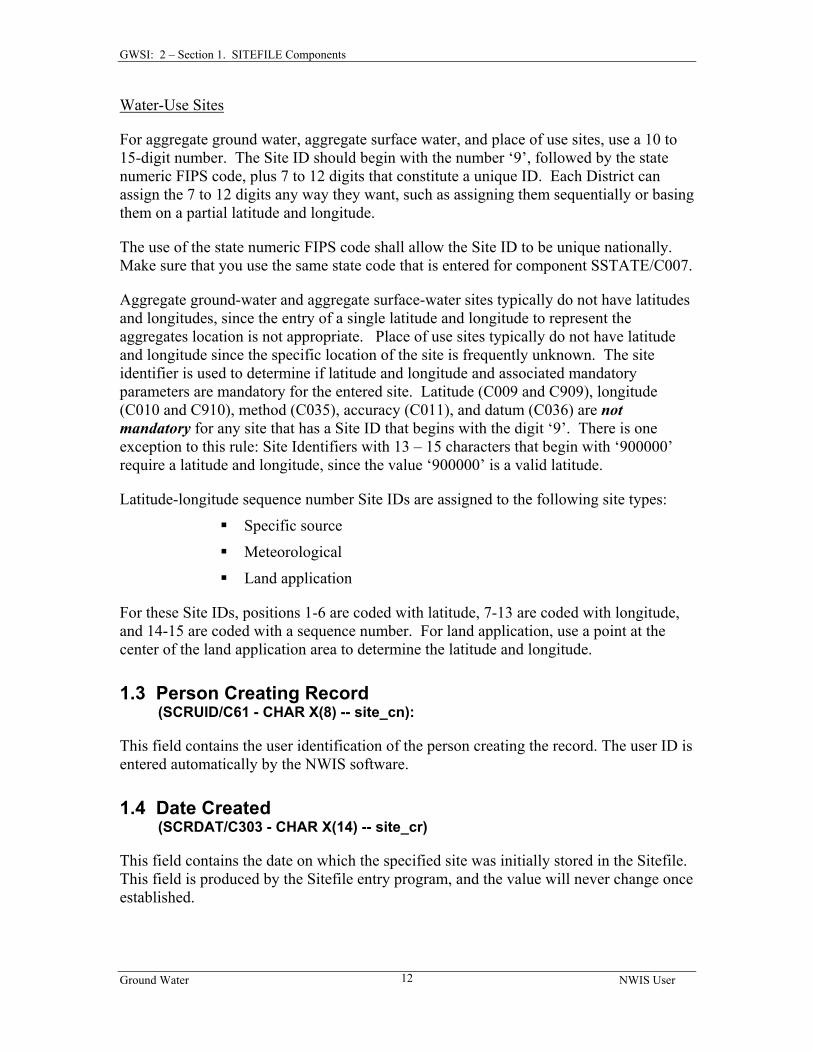
For aggregate ground water, aggregate surface water, and place of use sites, use a 10 to 15-digit number. The Site ID should begin with the number ‘9’, followed by the state numeric FIPS code, plus 7 to 12 digits that constitute a unique ID. Each District can assign the 7 to 12 digits any way they want, such as assigning them sequentially or basing them on a partial latitude and longitude.
The use of the state numeric FIPS code shall allow the Site ID to be unique nationally. Make sure that you use the same state code that is entered for component SSTATE/C007.
Aggregate ground-water and aggregate surface-water sites typically do not have latitudes and longitudes, since the entry of a single latitude and longitude to represent the aggregates location is not appropriate. Place of use sites typically do not have latitude and longitude since the specific location of the site is frequently unknown. The site identifier is used to determine if latitude and longitude and associated mandatory parameters are mandatory for the entered site. Latitude (C009 and C909), longitude (C010 and C910), method (C035), accuracy (C011), and datum (C036) are not mandatory for any site that has a Site ID that begins with the digit ‘9’. There is one exception to this rule: Site Identifiers with 13 – 15 characters that begin with ‘900000’ require a latitude and longitude, since the value ‘900000’ is a valid latitude.
Latitude-longitude sequence number Site IDs are assigned to the following site types:
Specific source
Meteorological
Land application
For these Site IDs, positions 1-6 are coded with latitude, 7-13 are coded with longitude, and 14-15 are coded with a sequence number. For land application, use a point at the center of the land application area to determine the latitude and longitude.
1.3 Person Creating Record (SCRUID/C61 - CHAR X(8) -- site_cn):
This field contains the user identification of the person creating the record. The user ID is entered automatically by the NWIS software.
1.4 Date Created (SCRDAT/C303 - CHAR X(14) -- site_cr)
This field contains the date on which the specified site was initially stored in the Sitefile. This field is produced by the Sitefile entry program, and the value will never change once established.
Ground Water NWIS User
12
GWSI: 2 – Section 1. SITEFILE Components 1.5 Person Updating Record
(SUPUID/C62 - CHAR X(8) -- site_mn)
This field contains the user identification of the person who last updated the record. The user ID is entered automatically by the NWIS software.
1.6 Date of Last Update (SUPDAT/C40 - CHAR X(14) -- site_md)
This field contains the date that the last valid transaction of add, modify, or delete occurred for any item of the specified site. The field is populated by the Sitefile update program.
1.7 Project Number (SPRNO/C5 - SECONDARY-KEY CHAR X(12) -- project_no):
This optional field is a retrieval key by means of which all the data collected for a particular project can be retrieved conveniently as a group. If the field is used, enter the 12-character WRD project number associated with data collection at the site. Where no single project number is applicable, leave the field blank.
1.8 Local Number Or Station Name Ground-water site (SNAME/C12 - MANDATORY SECONDARY-KEY CHAR X(24); Surface-water site (SNAME/C900 -MANDATORY SECONDARY-KEY CHAR X(50) -- station_nm):
For ground-water sites, if a District well-numbering system is used, enter the system's number for the site here. The local number should be entered as it is to be printed; include all edit characters to be used in printing the local number. This is a text field.
For surface-water stations, enter the station name and location or local identifier. This field contains 50 characters including spaces and punctuation. It should take a form similar to:
PENDLETON HILL BK NR LITTLETON FALLS, PA
Meaningful and approved abbreviations may be used if necessary (but avoided if possible). Local Number or Station Name must be unique.
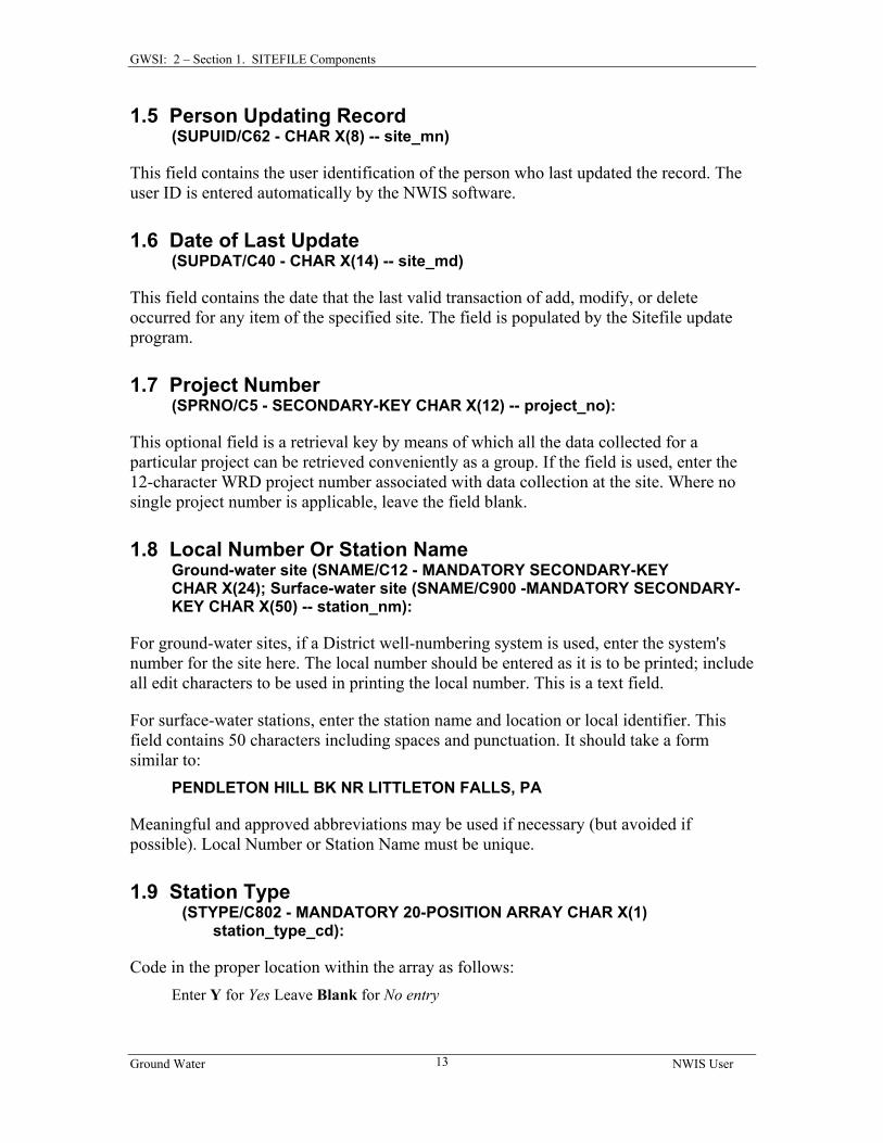
1.9 Station Type (STYPE/C802 - MANDATORY 20-POSITION ARRAY CHAR X(1) station_type_cd):
Code in the proper location within the array as follows: Enter Y for Yes Leave Blank for No entry
Ground Water NWIS User
13
GWSI: 2 – Section 1. SITEFILE Components For example, a ‘Y’ in position 1 (STYPE(1)) designates the site type as a “stream.” A ‘Y’ in position 5 designates the site type as a “spring.” Data will not be stored for the site if this field is blank.
Column on
screen
Position in Array
Type of Site (code) General Use
1 STYPE(1) Stream SW
2 STYPE(2) Lake or reservoir SW
3 STYPE(3) Estuary SW
4 STYPE(4) Specific Source
5 STYPE(5) Spring GW
6 STYPE(6) Ground water other than spring
GW
7 STYPE(7) Meteorological
8 STYPE(8) Outfall WU
9 STYPE(9) Diversion WU
0 STYPE(10) Land application WU
A STYPE(11) Aggregate ground water WU
B STYPE(12) Aggregate surface water WU
C STYPE(13) Water use/Place of use WU
D STYPE(14) Coastal WU
--- STYPE(15)-(20) Unassigned WU
Station Types 1-3 generally apply to Surface-water sites. Station Types 5-6 generally apply to Ground-water sites. Station Type 4 applies to sites that are not described by other Station Types.
Specific Source (Station Type 4) is provided to allow the entry of a site when none of the other Station Type codes apply. In general, the ‘SS’ site code should be used only when absolutely necessary.
Station Type 7: Meteorological Site: A site established to measure the physical, chemical, and dynamic properties and processes of the lower atmosphere. Properties and processes may include air temperature, humidity, precipitation, wind speed and direction, solar radiation, albedo, barometric pressure, and deposition rate, among others. Station Types 8-13 generally apply to Type of Water Use (WU) sites, but may be used by other disciplines where it is appropriate. Station Type 14 generally applies to Water Quality sites, but may be used by other disciplines where it is appropriate.
Ground Water NWIS User
14
GWSI: 2 – Section 1. SITEFILE Components
8. Outfall - A site where water or wastewater is returned to a surface-water body, e.g. the point where wastewater is returned to a stream.
9. Diversion - A site where water is withdrawn or diverted from a surface-water body (e.g. the point where the upstream end of a canal intersects a stream, or point where water is withdrawn from a reservoir).
10. Land application - site where the disposal of waste on land occurs. 11. Aggregate GW - A site that is defined by a geographic area where ground-water is
withdrawn or returned. An aggregate ground-water site type is selected when it is not possible or practical to describe the site as a spring or gw other than spring (well, well field, gallery/collector, or pond/recharge basin).
12. Aggregate SW - A site that is defined by a geographic area where surface water is withdrawn or returned. An aggregate surface-water site type is selected when it is not possible or practical to describe the site as a diversion, outfall, spring, or land application.
13. Place of Use - an entity or facility that uses/reuses, recycles, treats, distributes, collects, receives, or transfers water. Place-of-use sites can also be an aggregate source or return of water. Examples include: establishments (commercial or industrial facilities), hydroelectric power plants, and livestock operations.
14. Coastal – A site that is located off-shore but within the Coastal Shore Zone defined by The Submerged Lands Act, which establishes the seaward boundary of a state’s coastal zone as three nautical miles from shore or to the international boundary with Canada in the Great Lakes.
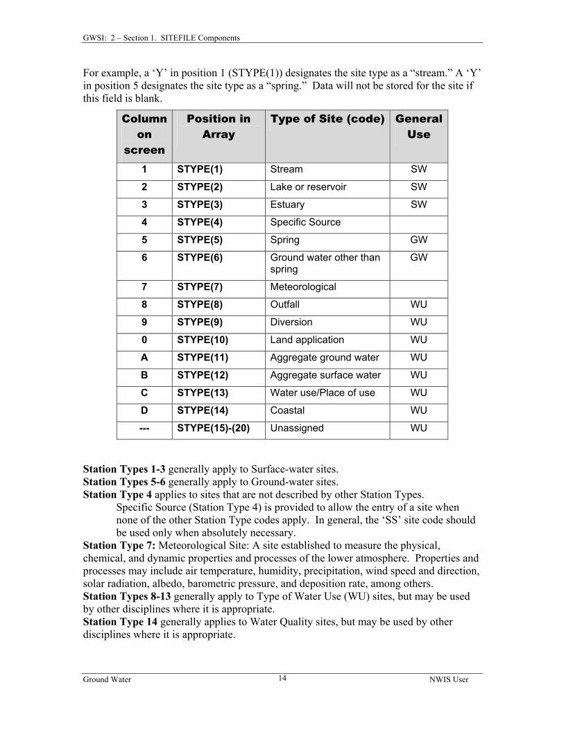
Many of the Station Type codes may be combined with other Station Type codes; however, there are many exceptions. Specific Source cannot be combined with any of the other Station Types. NWIS software will display warnings when Station Type combinations are not allowed. The following table shows the valid combinations:
Station Type Code Array Station Type Characteristics NNNYNNNNNNNNNNNNNNNN specific source NNNNYNNNNNNNNNNNNNNN spring NNNNYNYNNNNNNNNNNNNN spring+meteorological NNNNNYNNNNNNNNNNNNNN ground-water other than spring NNNNNYYNNNNNNNNNNNNN ground-water+meteorological NNNNNNYNNNNNNNNNNNNN meteorological NNNNNNNYNNNNNNNNNNNN outfall NNNNNNYYNNNNNNNNNNNN outfall+meteorological NNNNNNNNYNNNNNNNNNNN diversion NNNNNNYNYNNNNNNNNNNN diversion+meteorological NNNNNNNNNYNNNNNNNNNN land application NNNNNNYNNYNNNNNNNNNN land application+meteorological NNNNNNNNNNYNNNNNNNNN aggregate ground water NNNNNNNNNNNYNNNNNNNN aggregate surface water NNNNNNNNNNNNYNNNNNNN place of use NNNNNNYNNNNNYNNNNNNN place of use+meteorological NNNNNNNNNNNNNYNNNNNN coastal NNNNNNNYNNNNNYNNNNNN coastal+outfall NNNNNNYNNNNNNYNNNNNN coastal+meteorological NNNNNNNNYNNNNYNNNNNN coastal+diversion NNNNNNYYNNNNNYNNNNNN coastal+outfall+meteorological NNNNNNYNYNNNNYNNNNNN coastal+diversion+meteorological
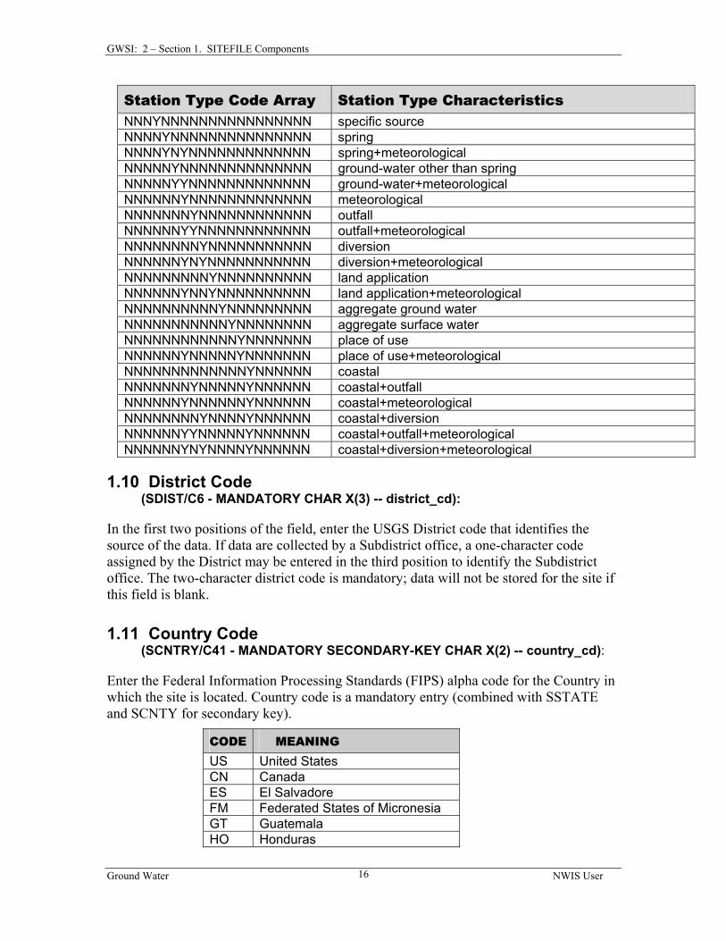
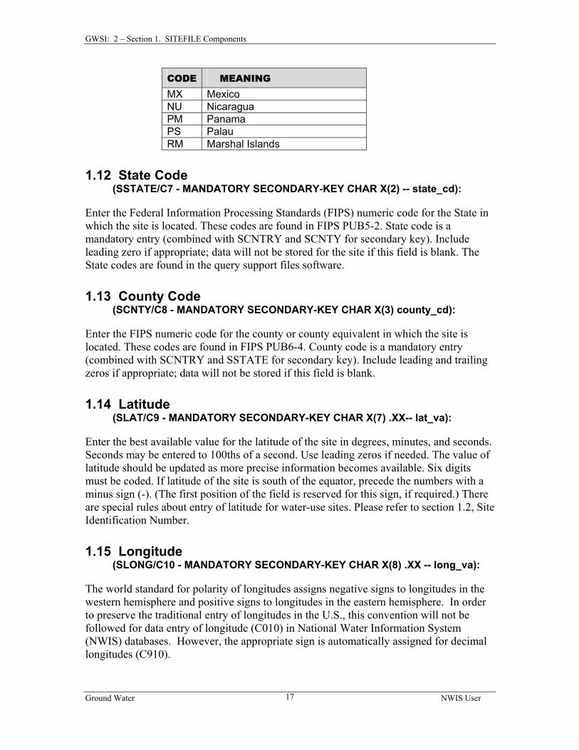
1.10 District Code (SDIST/C6 - MANDATORY CHAR X(3) -- district_cd):
In the first two positions of the field, enter the USGS District code that identifies the source of the data. If data are collected by a Subdistrict office, a one-character code assigned by the District may be entered in the third position to identify the Subdistrict office. The two-character district code is mandatory; data will not be stored for the site if this field is blank.
Enter the Federal Information Processing Standards (FIPS) alpha code for the Country in which the site is located. Country code is a mandatory entry (combined with SSTATE and SCNTY for secondary key).
CODE MEANING US United States CN Canada ES El Salvadore FM Federated States of Micronesia GT Guatemala HO Honduras
Ground Water NWIS User
16
GWSI: 2 – Section 1. SITEFILE Components
CODE MEANING MX Mexico NU Nicaragua PM Panama PS Palau RM Marshal Islands
Enter the Federal Information Processing Standards (FIPS) numeric code for the State in which the site is located. These codes are found in FIPS PUB5-2. State code is a mandatory entry (combined with SCNTRY and SCNTY for secondary key). Include leading zero if appropriate; data will not be stored for the site if this field is blank. The State codes are found in the query support files software.
1.13 County Code (SCNTY/C8 - MANDATORY SECONDARY-KEY CHAR X(3) county_cd):
Enter the FIPS numeric code for the county or county equivalent in which the site is located. These codes are found in FIPS PUB6-4. County code is a mandatory entry (combined with SCNTRY and SSTATE for secondary key). Include leading and trailing zeros if appropriate; data will not be stored if this field is blank.
1.14 Latitude (SLAT/C9 - MANDATORY SECONDARY-KEY CHAR X(7) .XX-- lat_va):
Enter the best available value for the latitude of the site in degrees, minutes, and seconds. Seconds may be entered to 100ths of a second. Use leading zeros if needed. The value of latitude should be updated as more precise information becomes available. Six digits must be coded. If latitude of the site is south of the equator, precede the numbers with a minus sign (-). (The first position of the field is reserved for this sign, if required.) There are special rules about entry of latitude for water-use sites. Please refer to section 1.2, Site Identification Number.
The world standard for polarity of longitudes assigns negative signs to longitudes in the western hemisphere and positive signs to longitudes in the eastern hemisphere. In order to preserve the traditional entry of longitudes in the U.S., this convention will not be followed for data entry of longitude (C010) in National Water Information System (NWIS) databases. However, the appropriate sign is automatically assigned for decimal longitudes (C910).
Ground Water NWIS User
17
GWSI: 2 – Section 1. SITEFILE Components Enter the best available value for the longitude of the site, in degrees, minutes, and seconds. Seconds may be entered to 100ths of a second. Use leading zeros for values <100. The value of longitude should be updated as more precise information becomes available. Seven digits must be coded. If longitude of the site is east of the Greenwich Meridian, precede the numbers with a minus sign (-). (The first position of the field is reserved for this sign, if required.)
The location should be entered as precisely as it is known, and the accuracy of the location should be indicated by a suitable entry in the lat/long accuracy (see Lat/Long Accuracy Method). There are special rules about entry of longitude for water-use sites. Please refer to section 1.2, Site Identification Number.
This field contains the calculated value of latitude in decimal degrees in terms of NAD83 datum. Latitude is calculated from degrees-minutes-seconds latitude (C009) and is converted, if necessary, to NAD83 datum. If conversion is not possible, this field is blank.
This field contains the calculated value of longitude in decimal degrees in terms of NAD83 datum. Longitude is calculated from degrees-minutes-seconds longitude (C010) and is converted, if necessary, to NAD83 datum. If conversion is not possible, this field is blank.
Enter the appropriate code on the schedule to indicate the accuracy of the latitude-longitude values. The codes and their meanings are:
CODE Meaning
H Accurate to +/- .01 second (differentially corrected GPS)
1 Accurate to +/- .1 second (differentially corrected GPS) 5 Accurate to +/- .5 second (Precise Positioning Service (PLGR/PPS GPS)) S Accurate to +/- 1 second R Accurate to +/- 3 seconds (Standard Positioning Service (SPS GPS)) F Accurate to +/- 5 seconds T Accurate to +/- 10 seconds M Accurate to +/- 1 minute U Unknown
Select the method used to determine latitude-longitude values from the following list:
Code Meaning C Calculated from land net D Differentially corrected Global Positioning System (GPS) G Global positioning system, uncorrected (Standard Positioning Service (SPS)
and Precise Positioning Service (PPS)) L Long-range navigation system M Interpolated from map N Interpolated from Digital Map R Reported S Transit, theodolite, or other surveying method U Unknown
1.20 Lat/Long Datum (SCORDM/C36 - MANDATORY CHAR X(10) -- coord_datum_cd):
Enter the horizontal datum code for the latitude/longitude coordinate datum:
Datum Meaning NAD27 North American Datum of 1927 NAD83 North American Datum of 1983 OLDAK Old Alaska (Mainland) and Aleutian Islands Datum OLDHI Old Hawaii OLDPR Old Puerto Rico and Virgin Islands Datum OLDSAMOA Old American Samoa Datum OLDGUAM Old Guam Datum
If new datums need to be added to this reference list, please refer to the Database Administrator’s Manual, section 6.3.1. Note: No conversions to alternate datums will be provided for the new datums.
1.21 Altitude of Land Surface (SDATUM/C16 - CHAR X(8) -- alt_va):
For ground-water sites, enter the altitude, in feet above mean sea level, of the land surface at the site. For surface-water sites, enter the altitude of the floor of the gage house or the point of zero flow in the stream channel, in feet. Precision to two decimal places can be coded, if available. Altitudes below mean sea level should be preceded by a minus sign (-). Note : An entry of Altitude also requires the entry of C17 (Method Altitude Determined), C28 (Altitude Accuracy), and C22 (Altitude Datum).
Altitude accuracy is mandatory when altitude is entered. Enter the accuracy of the altitude in terms of the possible error in feet. An accuracy of +/- 0.1 foot would be entered as ".1". Many altitudes are interpolated from the contours on topographic maps; accuracies determined in this way are generally entered as one-half of the contour interval.
Enter the appropriate code for the method used to determine the altitude. When Altitude is entered, the code is mandatory. The codes and their meanings are:
Code Meaning
A Altimeter D Differential Global Positioning System (GPS) G Global Positioning System L Level or other surveying method
M Interpolated from topographic map N Interpolated from digital elevation model (DEM) R Reported U Unknown
1.24 Altitude Datum (SALTDM/C22 - CHAR X(10) -- alt_datum_cd):
Altitude datum is mandatory when altitude is entered. Enter the vertical datum code for altitude:
Datum Meaning NGVD29 National Geodetic Vertical Datum of 1929 NAVD88 North American Vertical Datum of 1988 OLDAK Old Alaska (Mainland) and Aleutian Island Datum OLDPR Old Puerto Rico and Virgin Island Datum HILOCAL Local Hawaiian Datum ASLOCAL Local American Samoa Datum GULOCAL Local Guam Datum COE1912 COE Datum 1912
If new datums need to be added to this reference list, please contact your Database Administrator. Note: No conversions to alternate datums will be provided for the new datums.
Enter the legal description of the 10-acre tract in which the site is located, if applicable. The abbreviations NE, NW, SE, and SW are used for the quarter, quarter-quarter, and quarter-quarter-quarter. The smallest subdivision is listed first. Enter the appropriate code in the space. For "meridian," 5th principal meridian = 5, Boise meridian = B.
The format for the Land-Net Location is generally determined by the reference list /usr/opt/nwis/support/edit.tables/slndnt.ovr. Below is an example of land net for two Montana sites:
Enter the code that best describes the topographic setting in which the site is located. Topographic setting refers to the geomorphic features in the vicinity of the site. Allowable codes are:
Code Description A Alluvial fan B Playa C Stream channel D Local depression E Dunes F Flat surface G Flood plain H Hilltop K Sinkhole L Lake, swamp, or marsh M Mangrove swamp O Offshore (estuary) P Pediment S Hillside (slope) T Alluvial or marine terrace U Undulating V Valley flat (valleys of all sizes) W Upland draw
Ground Water NWIS User
21
GWSI: 2 – Section 1. SITEFILE Components The figure below is a diagrammatic sketch of the topographic features.
Ground Water NWIS User
22
GWSI: 2 – Section 1. SITEFILE Components
(A) Alluvial fan refers to a low, outspread, relatively flat to gently sloping mass of loose rock material shaped like an open fan or a segment of a cone. It is deposited by a stream at a place where it issues from a narrow mountain valley upon a plain or broad valley.
(B) Playa refers to a dried-up, vegetation-free, flat-floored area composed of thin, evenly stratified sheets of fine clay, silt or sand, and represents the bottom part of a shallow, completely closed or undrained desert lake basin in which water accumulates and is quickly evaporated, usually leaving deposits of soluble salts.
(C) Stream channel refers to the bed in which a natural stream of water runs. It is the trench or depression washed or cut into the surface of the earth by the moving water that it periodically or continuously contains. This term includes washes, arroyos, and coulees.
(D) A local depression is an area that has no external surface drainage. Some depressions, such as those in the High Plains, are only a few acres in extent, but others may cover a square mile. Do not use this designation for small "interdune depressions" or those on an undulating surface of glacial drift (use undulating). Do not use for large, closed basins, such as those on the Basin and Range province.
(E) Dunes refer to mounds and ridges of windblown, or eolian sand. This term should not be used for an isolated mound unless it has a rather extensive area and is of hydrologic significance to the site.
(F) A flat surface may be part of a larger feature, such as an upland flat, mesa or plateau, coastal plain, lake plain, or pediment terrace and valley flat, which are special varieties of flat surfaces, and are classified separately.
(G) Flood plain refers to the surface or strip of relatively smooth land adjacent to a river channel, constructed by the present river in its existing regimen and covered with water when the river overflows its banks at times of high water.
(H) A hilltop is the upper part of a hill or ridge above a well-defined break in slope. A site on the crest of an escarpment or top of a cuesta slope (see fig. 1) should be in this category. Use this category for hills of significant height (such as drumlins) above a generally flat area, but not for small "swells" a few feet high on an undulating surface such as a till plain or valley flat.
(K) A sinkhole is a special type of depression that results from the dissolving of soluble rocks (salt, gypsum, limestone) and the subsequent collapse of the earth into the solution cavity. As such, it has special significance to the understanding of the hydrology in the vicinity of the site.
(L) Lake refers to a body of inland water. However, this code also may be used for swampy or marshy areas where the ground may be saturated, or water may stand above the land surface for a significant period of time.
Ground Water NWIS User
23
GWSI: 2 – Section 1. SITEFILE Components
(M) Mangrove swamp refers to a tropical or subtropical marine swamp characterized by abundant mangrove trees.
(O) Offshore refers to a site along a coast or estuary that is continuously submerged.
(P) Pediment refers to a plain of combined erosion and deposition that forms at the foot of a mountain range.
(S) A hillside is the sloping side of a hill--that is, the area between a hilltop and valley flat. The important factor is the general aspect of the site. The steepness of the slope or height of the hill is not significant.
(T) An alluvial or marine terrace is generally a flat surface usually parallel to, but elevated above, a stream valley or coastline. Characteristically, steep slopes or escarpments separate the terrace from an adjacent upland on one side, and a lowland (coast or valley) on the other. Due to the effects of erosion, the terrace surface may not be as smooth as a valley flat, and within the general terrace area there may be undulating areas of dune sand or hill slopes.
(U) Undulating topography is characteristic of areas which have many small depressions and low mounds. An undulating surface is primarily a depositional feature, not an erosional one. The term should not be misused for areas that have slightly irregular surfaces resulting from erosion.
(V) A valley flat is a low flat area between valley walls and bordering a stream channel. It includes the flood plain, and generally is the flattest area in the valley. The surface may have a slight slope toward the main stream, toward the valley walls, or may be marked by valleys or smaller streams. Generally, the valley flat is separated from alluvial terraces, or from the upland, by a pronounced break in slope. Sometimes, however, the erosion of adjacent upland and the deposition of colluvium may make the outer edge of the alluvial flat. Use this code for sites in small valleys on a plain, if the site taps alluvium or the valley situation has hydrologic significance.
(W) An upland draw is a small natural drainageway or depression, usually dry, on a hillside or upland.
Enter the hydrologic-unit code for the cataloging unit in which the site is located. This eight-digit code consists of four parts:
1) Hydrographic region code
2) Subregion code designated by the Water Resources Council
3) Accounting unit within the National Water Data Network
4) Cataloging unit of the USGS's "Catalog of Information on Water Data"
Ground Water NWIS User
24
GWSI: 2 – Section 1. SITEFILE Components State Hydrologic Unit maps delineating the hydrographic boundaries of these units are available from the following address:
USGS Map Sales Federal Center, Box 25286 Denver, Colorado 80225.
If the site does not lie within a currently designated hydrologic unit (e.g., offshore wells), the eight-digit code 99999999 may be entered in this field.
Enter a two-digit code that further subdivides the hydrologic-unit code (C20). This two-digit code is defined by the District.
1.29 Time Zone Code (SMGTOF/C813 - MANDATORY CHAR X(6) -- tz_code):
Enter the appropriate 2 – 5 character time zone code for the site location. This is a mandatory field; data will not be stored for this site if this field is blank. This field is validated by a reference list.
1.30 Local Standard Time Flag (SLSTFL/C814 - MANDATORY CHAR X(1) -- local_tm_fg):
Enter a ‘Y’ for yes or an ‘N’ for no to indicate whether the site is in an area that switches to Local Standard Time (Daylight Savings Time) for a part of the year. This is a mandatory field; data will not be stored for this site if this field is blank.
Enter the name of the best available map on which the site can be located, preferably a USGS topographic quadrangle. If no topographic map is available for the area, a county highway map or similar map may be used. The map names table can be accessed by using an sql statement. For example logged on as NWIS type:
tsql <databasename> "select distinct (map_nm) from sitefile_01" >> output filename
Enter the scale of the map identified in the previous entry as follows: If the map scale is given as a ratio (1:24,000 1:62,500, and so forth) omit figure "1" and the colon, and enter the remaining number without the comma. If the scale is given in miles per inch, as on
Ground Water NWIS User
25
GWSI: 2 – Section 1. SITEFILE Components many county highway maps, convert the scale to a ratio (multiply miles per inch by 63,360) and enter the remaining number without the comma. A 7 1/2-minute quadrangle (1:24,000 scale) would be entered as 24000; a county or other map of 2 inches to the mile would be entered as 31680.
1.33 Agency Use of Site (SUSE/C803 - SECONDARY-KEY CHAR X(1) -- agency_use_cd):
Enter a code for the agency (SAGNCY) use of site. Allowable codes are:
A - Active data-collection site I - Inactive or discontinued data-collection site O - Inventory data site only
1.34 National Water-Use Code (SNWUSE/C39 - CHAR X(2) -- nat_water_use_cd):
Select the national water-use code from the following list:
Code Description WS Water supply
DO Domestic
CO Commercial
IN Industrial
IR Irrigation
MI Mining
LV Livestock
PH Hydroelectric power generation
ST Wastewater treatment
RE Reservoir evaporation
RM Remediation
TE Thermoelectric power water use
AQ Aquaculture
(WS) Water supply refers to water withdrawn by public and private water suppliers and delivered to various users. Water suppliers can be public suppliers (public or private water systems that provide water to at least 25 people or a minimum of 15 connections), or irrigation suppliers such as irrigation companies or irrigation districts.
(DO) Domestic refers to water for household purposes, such as drinking, food preparation, bathing, washing clothes and dishes, flushing toilets, and watering lawns and gardens. This is also called residential water use.
Ground Water NWIS User
26
GWSI: 2 – Section 1. SITEFILE Components (CO) Commercial refers to water used by commercial facilities such as hotels, restaurants,
office buildings, educational institutions, prisons, government and military facilities, and retail sales stores. For military bases and prisons, if domestic use cannot be determined, all withdrawals should go in the commercial category.
(IN) Industrial water use includes water for such purposes as processing, washing, and cooling in facilities that manufacture products. Electric power generation, mining, and the extraction of crude petroleum and gases are included in other water use categories.
(IR) Irrigation refers to artificial application of water on lands to assist in the growing of crops and pastures or to maintain vegetative growth in recreational lands such as parks and golf courses.
(MI) Mining refers to water use for extracting minerals occurring naturally, including solids such as coal and ores, liquids such as crude petroleum, and gases such as natural gas. Mining also includes uses associated with quarrying, well operations, milling, and other preparations customarily done at the mine site or as part of a mining activity. Mining does not include uses in processing, such as smelting, refining petroleum, or slurry pipeline operations.
(LV) Livestock water use is water used for livestock watering, feed lots, dairy operations, and other on-farm needs. Livestock includes all animals other than fish.
(PH) Hydroelectric power generation refers to the use of water to generate electricity at plants where the turbine generators are driven by falling water.
(ST) Wastewater treatment refers to water use at facilities engaged primarily in the collection, treatment, and disposal of wastewater conveyed through a sewer system.
(RE) Reservoir evaporation refers to water loss by evaporation from man-made impoundments with a normal capacity of 5,000 acre-feet or greater.
(RM) Remediation water use is water that is either (1) pumped from a contaminated area to control the flow direction of contaminants in ground-water or (2) pumped, treated, and either used or returned to ground-water or surface-water.
(TE) Thermoelectric power water use is water used in the process of generating thermoelectric power using fossil fuel, nuclear, or geothermal fuel sources. Thermoelectric power generation replaces the codes for fossil fuel thermoelectric generation (PF), nuclear thermoelectric power generation (PN), and geothermal thermoelectric power generation (PG).
(AQ) Aquaculture water use is water used for fish hatcheries and fish farms. Aquaculture replaces the code used for animal specialties (AS).
1.35 Type of Data Collected (SDATA/C804 - 30-POSITION ARRAY CHAR X -- data_types_cd):
Code in the proper location or locations in the array, one (or more) of the following codes:
A- Active data collection site I - Inactive or discontinued data collection site O - Inventory data site only
Ground Water NWIS User
27
GWSI: 2 – Section 1. SITEFILE Components These codes act as flags for the types of data collected:
Column on Screen
SDATA(30) 30*1 Types of data collected:
1 SDATA(1) Stage or water levels--continuous 2 SDATA(2) Stage or water levels--intermittent 3 SDATA(3) Water quality--continuous 4 SDATA(4) Water quality--intermittent 5 SDATA(5) Precipitation--continuous 6 SDATA(6) Precipitation--intermittent 7 SDATA(7) Evaporation--continuous 8 SDATA(8) Evaporation--intermittent 9 SDATA(9) Wind velocity 0 SDATA(10) Tide--continuous A SDATA(11) Tide--intermittent B SDATA(12) Sediment concentration C SDATA(13) Sediment particle size D SDATA(14) Peak flows E SDATA(15) Low flows F SDATA(16) Water Use -- SDATA(17)-(30) Unassigned
1.36 Instruments at Site (SINST/C805 - 30-POSITION ARRAY CHAR(1) -- instruments_cd):
Enter a ‘Y’ for yes, leave blank for no instrument at site; multiple instruments can be identified for a site. For example: a ‘Y’ in position 1 designates the site has a digital recorder, and a ‘Y’ in position 14 shows that a tipping-bucket rain gage is also operating at the site.
Columns on Screen
SINST(30) 30*1 Flags-instrumentation installed at this site (code):
1 SINST(1) Digital recorder
2 SINST(2) Graphic recorder
3 SINST(3) Telemetry--land line
4 SINST(4) Telemetry--radio
5 SINST(5) Telemetry--satellite relay
Ground Water NWIS User
28
GWSI: 2 – Section 1. SITEFILE Components
Columns on Screen
SINST(30) 30*1 Flags-instrumentation installed at this site (code):
6 SINST(6) AHDAS
7 SINST(7) Crest-stage gage
8 SINST(8) Tide gage
9 SINST(9) Deflection meter
0 SINST(10) Bubble gage
A SINST(11) Stilling well
B SINST(12) CR-type recorder
C SINST(13) Weighing rain gage
D SINST(14) Tipping-bucket rain gage
E SINST(15) Acoustic velocity meter
F SINST(16) Electromagnetic flow meter
G SINST(17) Pressure Transducer
--- SINST(18)-(30) Unassigned
1.37 Date Site Established or Inventoried (SINVDT/C711 - CHAR X(8) -- inventory_dt):
Enter the date that the site was established or inventoried in the following format: MMDDYYYY (12011984). If the month or day is not known, enter blanks in the spaces. Use leading zeros for month or day values less than 10.
This field is designed for a significant remark about the site. If multiple remarks need storing, use the remarks record in the Miscellaneous File (See Miscellaneous File Components – Chapter 2.5.)
1.39 Type of Ground-Water Site (SGWTYPE/C2 - MANDATORY FOR GW SITES CHAR(1) -- gw_type_cd):
Enter the code indicating the type of site to which these data apply. Data will not be stored for the site if this field is blank. The codes and their meanings are:
Ground Water NWIS User
29
GWSI: 2 – Section 1. SITEFILE Components
Code Meaning
C Collector or Ranney type well
D Drain dug to intercept the water table or potentiometric surface to either lower the ground-water level or serve as a water supply
E Excavation
H Sinkhole
I Interconnected wells, also called connector or drainage wells; that is, a well interconnected via an underground lateral
M Multiple wells; use only for well field consisting of a group of wells that are pumped through a single header and for which little or no data about the individual wells are available
O Outcrop
P Pond dug to intercept the water table or potentiometric surface and serve as a water supply
R River Pump (A pump installed in a surface water source such as a river, lake, pond, canal, or drainage ditch from which water is pumped for use.)
S Spring (used only on spring schedule)
T Tunnel, shaft, or mine from which ground-water is obtained
W Well, for single wells other than wells of the collector or Ranney type.
X Test hole, not completed as a well.
Note: R=River Pump is available to surface water station types. This field is NOT mandatory for surface water station types.
1.40 Record Ready for Web (SIWBFG/C32 - CHAR(1)—site_web_cd)
This field contains the status and availability of a record for display on the World Wide Web. Only records flagged with a ‘Y’ are made available on the Web. Codes Y and N are set by the NWIS software.
Code Meaning
Y Record has been checked and is ready for Web display.
C Record has not been checked. No Web display.
N Record has failed one or more data verification checks. No Web display.
P Record is proprietary. No Web display.
L Local use only. No Web display.
Ground Water NWIS User
30
GWSI: 2 – Section 1. SITEFILE Components 1.41 Data Reliability
Enter the code indicating the reliability of the data available for the site. Data will not be stored for the site if this field is blank. The codes and their meanings are:
Code Meaning
C Data have been field checked by the reporting agency.
L Location not correct.
M Minimal data.
U Data have not been field checked by the reporting agency, but the reporting agency considers the data reliable.
Enter the code that best represents the reliability of the site's inventory data according to the reporting agency. When in doubt, always select the code that portrays the lesser confidence. (Note: The codes are listed in order of decreasing confidence.)
1.42 Date of First Construction
(SCONDT/C21 - CHAR X(8) -- construction_dt):
Enter the earliest date for which data are available for the site or the date when construction began, whichever is earlier. The date stored is checked against dates for data entered afterwards, and no data will be accepted if associated with an earlier date than that stored. If the month or day are not known, enter blanks in the spaces, and use leading zeros for month or day values less than 10. Enter four digits for the year.
1.43 Primary Use of Site (SUSE1/C23 - MANDATORY (GROUND WATER) except Springs CHAR(1) -- site_use_1_cd):
Enter the code indicating the principal use of the site or the purpose for which the site was constructed (the former always holds precedence over the latter). If the site is used for more than one purpose, enter the principal use here and enter the subordinate uses in the following two fields (secondary and tertiary). Data will not be stored for the site if this field is blank. The codes and their meanings are:
Code Meaning A Anode C Standby emergency supply D Drain E Geothermal G Seismic H Heat reservoir
Ground Water NWIS User
31
GWSI: 2 – Section 1. SITEFILE Components
Code Meaning M Mine O Observation P Oil or gas well R Recharge S Repressurize T Test hole U Unused site V Withdrawal/Return W Withdrawal of water X Waste disposal Z Destroyed
(A) Anode is a hole used as an electrical anode. Include in this category wells used solely to
ground pipelines or electronic relays and other installations.
(C) Standby emergency supply refers to a water-supply source that is used only when the principal supply of water is unavailable.
(D) Drain refers to the drainage of surface-water into the ground-water.
(E) Geothermal well is a hole drilled for geothermal energy development. Use this category for "dry" geothermal wells or wells into which water is injected for heating. For "wet" geothermal wells, through which water is withdrawn, use "W - withdrawal of water" for the use of site, and "E - power generation" for the primary use of water.
(G) Seismic hole is one drilled for seismic exploration. If it has been converted to water supply, it should be listed as “W-Withdrawal.” A seismic hole used as an observation well should be coded as “O-Observation well.”
(H) Heat reservoir refers to a well in which a fluid is circulated in a closed system. Water is neither added to, nor removed from, the aquifer.
(M) Mine includes any tunnel, shaft, or other excavation constructed for the extraction of minerals.
(O) Observation well is a cased test-hole or well, drilled for either water-level or water-quality observations. Do not use this category for an oil-test hole, or water-supply well used only incidentally as an observation well.
(P) Oil or gas well is any well or hole drilled in search of, or for production of, petroleum or gas. It includes any oil or gas production well, dry hole, core hole, injection well drilled for secondary recovery of oil, etc. An oil-test hole converted to a water-supply well should be classified as “withdrawal (W).”
(R) Recharge site is a site constructed or converted for use in replenishing the aquifer. Use this category for wells that are used to return water to the aquifer after use, such as those for returning air-conditioning water.
(S) Repressurize refers to pumping water into an aquifer in order to increase the pressure in the aquifer for a specific purpose, for example, water flood purposes in oil fields.
Ground Water NWIS User
32
GWSI: 2 – Section 1. SITEFILE Components (T) Test hole is an uncased hole (or one cased only temporarily) that was drilled for water, or
for geologic or hydrogeologic testing. It may be equipped temporarily with a pump in order to make a pumping test, but if the well is destroyed after testing is completed, it is still a test hole. A core hole drilled as a part of mining or quarrying exploration work should be in this class.
(U) An unused site is an abandoned water-supply site or one for which no use is contemplated. At an abandoned farmstead, a well originally used for domestic purposes may be classed as unused, even though it is equipped with a pump. Similarly, a stock well with a pump may become unused when a pasture or corral is put into cultivation. An irrigation well that is not equipped with a pump, nor used because the yield is too low or the water is too mineralized, belongs in this class.
(V) Ground-water sites that are used to both withdraw and inject water to a well, such as an irrigation well used to return water to the aquifer during nonpumping periods, is a well for withdrawing water, not a drainage or recharge well.
(W) Withdrawal of water refers to a site that supplies water for one of the purposes shown under use of water. It includes a dewatering well, if the dewatering is accomplished by pumping ground water.
(X) A waste-disposal site is one used to convey industrial waste, domestic sewage, oil-field brine, mine drainage, radioactive waste, or other waste fluid into an underground zone. An oil-test or deep water well converted to waste disposal should be in this category.
(Z) A destroyed site is one that is no longer in existence. The casing of most destroyed wells will be pulled, but some may be plugged or filled. Do not use this category for an abandoned site that merely is not in use.
1.44 Secondary Site Use (SUSE2/C301 - CHAR X(1) -- site_use_2_cd):
If the site is used for more than one purpose, show the secondary use here. Enter an appropriate code from the above list.
1.45 Tertiary Site Use (SUSE3/C302 - CHAR X(1) -- site_use_3_cd):
If needed, a third use of the site can be shown here. Enter an appropriate code from the above list.
1.46 Primary Use of Water (SWUSE1/C24 - SECONDARY-KEY CHAR X(1) -- water_use_1_cd):
Enter the code indicating the principal use of water from the site. If water from the site is used for more than one purpose, enter the principal use here and enter the subordinate uses in the following two fields. The codes and their meanings are:
Ground Water NWIS User
33
GWSI: 2 – Section 1. SITEFILE Components
Code Meaning A Air conditioning B Bottling C Commercial D Dewater E Power generation F Fire protection H Domestic I Irrigation J Industrial (cooling) K Mining M Medicinal N Industrial P Public supply Q Aquaculture (in remarks) R Recreation S Stock supply T Institutional U Unused Y Desalination Z Other (explain)
(A) Air-conditioning refers to water supply used solely or principally for heating or cooling a building. Water used to cool industrial machinery belongs in the industrial category, not in the air-conditioning category.
(B) Bottling refers to water that is bottled for potable purposes (see Medicinal).
(C) Commercial use refers to use by a business establishment that does not fabricate or produce a product. Filling stations and motels are examples of commercial establishments. If some product is manufactured, assembled, remodeled, or otherwise fabricated, use of water for that plant should be considered industrial, even though the water is not used directly in the product or in the manufacturing of the product.
(D) Dewatering refers to water pumped for dewatering a construction or mining site, or to lower the water table for agricultural purposes. In this respect, it differs from a drainage well that is used to drain surface water underground. If the main purpose for which the water is withdrawn is to provide drainage, dewatering should be indicated even though the water may be discharged into an irrigation ditch and subsequently used to irrigate land.
(E) Power generation refers to use of water for generation of any type of power. Water for cooling and boiler make-up water are included.
(F) Fire protection refers to the principal use of the water and should be indicated if the site was constructed principally for this purpose, even though the water may be used at times to supplement an industrial or public supply, to irrigate a golf course, fill a swimming pool, or for other use.
(H) Domestic use is water used to supply household needs, principally for drinking, cooking, washing, and sanitary purposes, but including watering a lawn and caring for a few pets. Most domestic wells will be at suburban or farm homes, but wells supplying small
Ground Water NWIS User
34
GWSI: 2 – Section 1. SITEFILE Components
quantities of water for domestic purposes for one-classroom schools, turnpike gates, and similar installations should be in the domestic category.
(I) Irrigation refers to the use of water to irrigate cultivated plants. Most irrigation sites will supply water for farm crops, but the category should include wells used to water the grounds of schools, industrial plants, or cemeteries, if more than a small amount of water is pumped and that is the sole use of the water. Water used to irrigate golf courses or park lands is also coded as Irrigation.
(J) Industrial cooling refers to a water supply used solely for cooling industrial machines.
(K) Mining refers to a water supply used solely for mining purposes.
(M) Medicinal refers to water purported to have therapeutic value. Water may be used for bathing and/or drinking. If use of water is mainly because of its claimed therapeutic value, use this category even though the water is bottled.
(N) Industrial use is within a plant that manufactures or fabricates a product. The water may or may not be incorporated into the product being manufactured. Industrial water may be used to cool machinery, to provide sanitary facilities for employees, to air-condition the plant, and to irrigate the ground at the plant.
(P) Public Supply use is water that is pumped and distributed to several homes. Such supplies may be owned by a municipality or community, a water district, or a private concern. In most states, public supplies are regulated by departments of health which enforce minimum safety and sanitary requirements. If the system supplies five or more homes, it should be considered a public supply, as four or less classify use as domestic. Water supplies for trailer or summer camps with five or more living units should be in this category, but motels and hotels are classified as commercial. Most public supply systems also furnish water for a variety of other uses, such as industrial, institutional, and commercial.
(Q) Aquaculture refers to a water supply used solely for aquaculture, such as fish farms.
(R) Recreation refers to water discharged into pools (or channels which are dammed downstream to form pools), for swimming, boating, fishing, ice rinks, and other recreational uses. Water used to irrigate golf courses is coded as “I-Irrigation.”
(S) Stock Supply refers to the watering of livestock.
(T) Institutional refers to water used in the maintenance and operation of institutions such as large schools, universities, hospitals, rest homes, or similar installations. Owners of institutions may be individuals, corporations, churches, or governmental units.
(U) Unused means water is not being removed from the site for one of the purposes described above. A test hole, oil or gas well, recharge, drainage, observation, or waste-disposal well will be in this category.
Do not use this classification for an irrigation, domestic, stock, or other well during "off season" or temporary periods of nonuse. The use of water from a newly constructed site should be considered as the use for which it is intended even though it may not yet be in use when inventoried.
(Y) Desalination refers to water used in a desalting process whereby dissolved solids are removed to make water potable or suitable for other uses. Enter the type of use of the desalinated water in the next column, "Secondary Water Use."
(Z) Other refers to miscellaneous uses not included in the listed categories.
Ground Water NWIS User
35
GWSI: 2 – Section 1. SITEFILE Components 1.47 Secondary Use of Water
(SWUSE2/C25 - CHAR X(1) -- water_use_2_cd):
If water from the site is used for more than one purpose, show the secondary use here. Enter an appropriate code from the list above.
1.48 Tertiary Use of Water (SWUSE3/C26 - CHAR X(1) -- water_use_3_cd):
If needed, a third use of water from the site can be shown here. Enter an appropriate code from the list above.
1.49 Aquifer Type Code (SAQTYP/C713 - CHAR X(1) -- aqfr_type_cd):
Enter the appropriate code to describe the type of aquifer(s) penetrated by the well.
Code Aquifer Type
U Unconfined single aquifer
N Unconfined multiple aquifers
C Confined single aquifer
M Confined multiple aquifer
X Mixed (confined and unconfined multiple aquifers)
Enter the eight-character code identifying the primary aquifer unit from which the water is obtained. Aquifer codes are given in the "Catalog of Aquifer Names and Geologic Unit Codes used by the Water Resources Division." Codes are also available in the online file: /usr/opt/nwis/support/aageol.all.states. 1.51 Hole Depth
(SHDEPT/C27 - CHAR X(8) -- hole_depth_va):
Enter the total depth to which the hole was drilled, in feet below the land-surface datum, even though it may have been plugged back in completing the well. For collector or Ranney type wells, enter the depth of the central shaft. For multiple-well fields, interconnected wells, ponds, tunnels, or drains, leave the space blank. Ground Water NWIS User
36
GWSI: 2 – Section 1. SITEFILE Components 1.52 Well Depth
(SWDEPT/C28 - CHAR X(8) -- well_depth_va):
Enter the depth of the finished well, in feet below land-surface datum. The depth of the well is the greatest depth to which the well can be sounded; if measurement is not practical, enter the reported depth at which the well was finished.
This field should be completed for wells whenever possible. If the hole depth is given, all other depths entered on the schedule will be compared with it for validity; well depth cannot exceed hole depth. Precision may be carried to two decimal places.
1.53 Source of Depth Data (SWDSRC/C29 - CHAR X(1) -- depth_src_cd):
Enter an appropriate code to indicate how the information about the depth of the well was obtained. The codes and their meanings are:
Code Meaning A Reported by another government agency. Do not use A if the reporting
agency is the owner of the well--use O. D From driller's log or report. G Private geologist-consultant or university associate. L Depth interpreted from geophysical logs by personnel of source agency. M Memory (owner, operator, driller): less reliable than O – reported by owner. O Reported by the owner of the well. R Reported by person other than the owner, driller, or another government
agency. S Measured by personnel of reporting agency. Z Other source (explain in remarks).
1.54 Drainage Area (SAREA/C808 - CHAR X(8) -- drain_area_va):
Enter the total drainage area of the drainage basin for a surface-water site (in square miles). If the value contains a fractional part of a square mile, the decimal point must be entered.
1.55 Contributing Drainage Area (SCNTRB/C809 - CHAR X(8) -- contrib_drain_area_va):
Enter the contributing drainage area at a surface-water site (in square miles). This item should be entered only if the contributing area is different from the total drainage area. This situation can occur when part of the drainage area consists of very porous soil or depressions that either allow all runoff to enter the ground-water, or traps the water in ponds so that rainfall does not contribute to runoff. A transbasin diversion can also affect the total drainage area.
Ground Water NWIS User
37
GWSI: 2 – Section 1. SITEFILE Components 1.56 Other Ground-Water Data Files
(SGWFLE/C712 - MANDATORY FOR GROUND-WATER 30-POSITION ARRAY CHAR X -- gw_file_cd):
This field is automatically set by the EDIT/UPDATE program and reflects the availability of other ground-water data. This component appears in dump format output but may not be meaningful. The contents of this field should be used with great caution:
Y -- Yes, file exists. N -- No, file does not exist.
SGWFLE(20) 20*1 Data in other ground-water files:
SGWFLE(1) Construction (GW.CONS) data for site SGWFLE(2) Miscellaneous (GW.MISC) data for site SGWFLE(3) Discharge (GW.DISC) data for site SGWFLE(4) Geohydrologic (GW.GEOH) data for site SGWFLE(5) Hydraulic (GW.HYDR) data for site SGWFLE(6) Water-level (GW.LEV) data for site SGWFLE(7) Observation-heading (GW.OBS) data for site SGWFLE(8)-(20) Unassigned
Ground Water NWIS User
38
GWSI: 2 – Section 2. Construction Components Section 2. Construction Components
Sub- Section Description 2.1 Source agency code (C4) MANDATORY 2.2 Site identification number (C1)MANDATORY 2.3 Record type (see below) MANDATORY 2.4 Record sequence number MANDATORY 2.5 Record sequence number of child MANDATORY 2.6 Person creating record 2.7 Date and time created 2.8 Person updating record 2.9 Date and time of last update
2.10 Record ready for Web 2.11 Remainder of record (depend on record type)
The CONSTRUCTION record data are grouped into and identified by eight component record types related to the construction of the well. The following is a list of the record types, brief description of the contents of the data record types and the construction data table names.
Record Type Description of Contents Data Table Name
CONS Includes basic construction data (gw_cons_##) HOLE Includes hole data (gw_hole_##) CSNG Includes casing data (gw_csng_##) OPEN Includes openings data (gw_open_##)
LIFT Includes lift, major pump, and standby pump (gw_lift_##) REPR Includes minor repairs data (gw_repr_##) SPNG Includes spring data (gw_spng_##)MPNT Includes measuring-point data (gw_mpnt_##)
All Construction records contain Source Agency, Site Identification (Site ID) number, Record Type, and Record Sequence Number to uniquely identify the record in the database.
The CONS Record is associated with ‘Child’ records and its Record Sequence Number becomes the Parent Sequence Number. HOLE, CSNG, and OPEN are the child records of CONS and have an additional Child Sequence Number assigned which uniquely identifies these records; child records MUST have a parent (in this instance CONS) record.
This is the agency that reported the data. The reporting agency is mandatory and a part of the primary key. Data for the site will not be stored if this field is blank.
Ground Water NWIS User
39
GWSI: 2 – Section 2. Construction Components 2.2 Site Identification Number
This is the 15-digit site identification (Site ID) number of the site to which the construction data applies. If the site has not been entered into the Sitefile, this operation must be completed before the construction data are input. The Site ID number is mandatory and a part of the primary key.
2.3 Record Type (CDRTYP - MANDATORY SECONDARY-KEY CHARX(4)):
The RECORD TYPE identifies the category of data included in the record. There are eight categories with the CONSTRUCTION data. This field is mandatory and is a secondary key. Data for the site will not be stored if this field is blank. The categories are as follows:
Record Type
Description
CONS Construction record (C754) HOLE Hole record (C756) CSNG Casing record (C758) OPEN Openings record (C760)
LIFT Lift record (C752) REPR Repairs record (C762) SPNG Spring record (C764) MPNT Measuring-point record (C766)
2.4 Record Sequence Number or Sequence Number of Parent (CDRNUM - MANDATORY PRIMARY-KEY CHAR X(3)):
The record sequence number or sequence number of parent (HOLE, CSNG, OPEN sub-records) is assigned at the time of data entry to keep data by record type in a logical order. This number is mandatory and a part of the primary key. The component number for the record sequence number depends on the record type as follows:
Record Description Attribute Name CONS Construction record (C723) cons_seq_nu HOLE Parent construction record (C59) cons_seq_nu CSNG Parent construction record (C901) cons_seq_nu OPEN Parent construction record (C902) cons_seq_nu LIFT Lift record (C254) lift_seq_nu REPR Repairs record (C165) repr_seq_nu SPNG Spring record (C727) spng_seq_nu MPNT Measuring-point record (C728) mpnt_seq_nu
Ground Water NWIS User
40
A parent CONS record must be established before HOLE, CSNG, or OPEN sub-record can be entered. HOLE, CSNG, or OPEN sub-records are identified using Parent
GWSI: 2 – Section 2. Construction Components Sequence number, which relates the sub-record to the appropriate CONS record, and Record Sequence Number for the sub or ‘child’ record. For example, enter the sequence number (C723) of the construction (CONS) record to which the CSNG record is to be related. The CONS sequence number (C723) is the parent sequence number of HOLE, CSNG, and OPEN records, and relates the CSNG data to the proper construction record. This entry is mandatory; no information about the casing will be stored without a valid value for this field.
2.5 Record Sequence Number of Child Record (for HOLE, CSNG, & OPEN only)
(CDCRNM - MANDATORY CHAR X(3)):
Enter the sequence number of the child record. This number is assigned at the time of data entry to keep data by record type in a logical order; it is mandatory and a part of the primary key. Data for the site will not be stored if this field is blank.
Record Description Attribute Name HOLE Hole record (C724) hole_seq_nu CSNG Casing record (C725) csng_seq_nu OPEN Openings record (C726) open_seq_nu
2.6 Person Creating Record (CDCUID - CHAR X(8)):
This field contains the user identification of the person creating the record. User identification of the person creating the construction is entered automatically by the NWIS Software.
Record Description Attribute Name CONS Construction record (C403) cons_cn HOLE Hole record (C406) hole_cn CSNG Casing record (C409) csng_cn OPEN Openings record (C412) open_cn LIFT Lift record (C415) lift_cn REPR Repairs record (C418) repr_cn SPNG Spring record (C421) spng_cn MPNT Measuring-point record (C424) mpnt_cn
2.7 Date and Time Created (CDCRDT/C404 - CHAR X(14)):
This field contains the date and time that the construction record was created. The date and time are entered automatically by the NWIS software.
Ground Water NWIS User
41
GWSI: 2 – Section 2. Construction Components
Field Component Attribute Name CONS Construction record (C404) cons_cr HOLE Hole record (C407) hole_cr CSNG Casing record (C410) csng_cr OPEN Openings record (C413) open_cr LIFT Lift record (C416) lift_cr REPR Repairs record (C419) repr_cr SPNG Spring record (C422) spng_cr MPNT Measuring-point record (C425) mpnt_cr
2.8 Person Updating Record (CDUUID/C405 - CHAR X(8)):
This contains the user identification (User ID) of the person updating the construction record. The user ID is entered automatically by the NWIS software.
Record Description Attribute Name CONS Construction record (C405) cons_mn HOLE Hole record (C408) hole_mn CSNG Casing record (C411) csng_mn OPEN Openings record (C414) open_mn LIFT Lift record (C417) lift_mn REPR Repairs record (C420) repr_mn SPNG Spring record (C423) spng_mn MPNT Measuring-point record (C426) mpnt_mn
2.9 Date and Time of Last Update (CDUPDT/C755 - CHAR X(14)):
This contains the date and time that the construction record was last updated. The date and time are entered automatically by the NWIS software.
Record Description Attribute Name CONS Construction record (C755) cons_md HOLE Hole record (C757) hole_md CSNG Casing record (C759) csng_md OPEN Openings record (C761) open_md LIFT Lift record (C753) lift_md REPR Repairs record (C763) repr_md SPNG Spring record (C765) spng_md MPNT Measuring-point record (C767) mpnt_md
2.10 Record Ready for Web (CDWBFG/C850 - SK7 - CHAR X):
This field contains the status and availability of a record for display on the World-Wide-Web.
Ground Water NWIS User
42
GWSI: 2 – Section 2. Construction Components The codes and their meanings are:
Code Meaning
Y Yes-Record has been checked and is ready for Web display. C Conditional-Record has not been checked. No Web display. P Proprietary Record. No Web display. L Local use only. No Web display.
Record Description Attribute Name CONS Construction record (C850) cons_web_cd HOLE Hole record (C851) hole_web_cd CSNG Casing record (C852) csng_web_cd OPEN Openings record (C853) open_web_cd LIFT Lift record (C854) lift_web_cd REPR Repairs record (C855) repr_web_cd SPNG Spring record (C856) spng_web_cd MPNT Measuring-point record (C857) mpnt_web_cd
2.11 Data Dependent on Record Type
2.11.1 Construction Record -- CDRTYP = CONS
Data elements common to all Construction Data Records for CONS Record Type are entered following the instructions in sections 2.1 through 2.10. Here is a brief review for your convenience:
Source agency Site identification number Record type (CONS) Record sequence number Person creating record Date and time created Person updating record Date and time of last update Record ready for Web
The entry of construction data is identified by coding "CONS" for the type of construction record. The CONS components are entered as follows:
Ground Water NWIS User
43
GWSI: 2 – Section 2. Construction Components
Sub- Section
Attribute Name Description
2.11.1.1 cons_dt Date of construction (C60) 2.11.1.2 cons_contractor_nm Name of contractor (C63) 2.11.1.3 cons_src_cd Source of construction data (C64) 2.11.1.4 cons_meth_cd Method of construction (C65) 2.11.1.5 finish_cd Type of finish (SK5) (C66) 2.11.1.6 seal_cd Type of seal (C67) 2.11.1.7 seal_depth_va Depth to bottom of seal (C68) 2.11.1.8 dev_meth_cd Method of development (C69) 2.11.1.9 dev_du Hours of development (C70) 2.11.1.10 special_treat_cd Special treatment (C71) during development
2.11.1.1 Date of Completed Construction (CDCODT/C60 - SK4 - CHAR X(8) -- cons_dt):
Enter the date on which the work was completed. If the day or month is not known, enter blanks in the spaces. Use leading zeros for values of day and month less than ten, and specify all four digits for the year. For many sites, this date will be the same as the one entered earlier as date of first construction (C21); however, it must be entered here. All GWSI related dates are validated using this date; entry for any other date must be later than or equal to this date.
2.11.1.2 Name of Contractor/Driller (CDCOCT/C63 - CHAR X(12) -- cons_contractor_nm):
Enter the name of the individual or company that did the work. If needed to fit the space, use meaningful abbreviations or acronyms for company names.
2.11.1.3 Source of Construction Data (CDCOSC/C64 - CHAR X(1) -- cons_src_cd):
Enter the code that best indicates the source of construction data or who furnished the data. The codes are the same as those used for Source of Depth Data. The codes and their meanings are:
Ground Water NWIS User
44
GWSI: 2 – Section 2. Construction Components
Code Meaning A Reported by another government agency. Do not use A if the reporting agency is
the owner of the well--use O. D From driller's log or report. G Private geologist-consultant or university associate. L Depth interpreted from geophysical logs by personnel of source agency. M Memory (owner, operator, driller): less reliable than O – reported by owner. O Reported by the owner of the well. R Reported by person other than the owner, driller, or another government agency. S Measured by personnel of reporting agency. Z Other source (explain in remarks).
2.11.1.4 Method of Construction
(CDCOME/C65 - CHAR X(1) -- cons_meth_cd):
Enter the code that best indicates the method by which the site was constructed. Allowable codes are:
Code Description Code Description A Air-rotary P Air percussion B Bored or augered R Reverse rotary C Cable-tool T Trenching D Dug V Driven H Hydraulic rotary W Drive and wash J Jetted Z Other (explain in remarks)
(A) Air-rotary method is one in which a stream of air is used to cool the bit and bring
the rock cuttings to the surface.
(B) A bored or augered hole is one in which the earth materials are cut and removed from the hole with an auger. The auger may be powered by hand or machinery.
(C) Cable-tool refers to a well drilled by the familiar "percussion" or "churn-drill" method, whereby a heavy drilling tool is raised and lowered with enough force to pulverize the rock. The rock debris is commonly removed from the hole with a bailer. The California mud-scow method is a special variation of the cable-tool method.
(D) Dug holes are excavated by hand tools or power-driven digging equipment. Caissons, Ranney-type collectors, and galleries belong in this classification, even though they may have laterals that are driven or jetted. Tunnels would also be in this category.
(H) The hydraulic-rotary well is constructed by rotating a length of pipe (drill stem) equipped with a bit that cuts or grinds the rocks. Water or drilling mud is pumped down the drilling stem. Cuttings are carried to the surface in the annular space
Ground Water NWIS User
45
GWSI: 2 – Section 2. Construction Components
between the drilling stem and the wall of the hole. Note that separate categories are provided for air-rotary and reverse-rotary.
(J) Jetted wells are excavated by using high-velocity streams of water pumped through a pipe having a restricted opening or "jetting" nozzle. For some types of earth materials a cutting bit is attached to the end of the jetting pipe. The material cut or washed from the hole is carried to the surface in the annular space outside the pipe as by the hydraulic-rotary method. This method is most suitable for construction of small-diameter wells in unconsolidated material.
(P) An air-percussion drill is a cutting tool powered by compressed air. It uses a rapid percussion effect, coupled with rotary action, to drill hard rocks. Compressed air also is used to blow the cuttings from the hole. Air-percussion drills are generally used in conjunction with air-rotary drilling rigs.
(R) Reverse rotary is similar to the hydraulic rotary except that the water or drilling mud flows down the annular space between the drilling stem and the wall of the hole and the cuttings are pumped out through the drill stem.
(T) Trenching refers to the construction of a sump or open pit from which ground water may be pumped. Trenching may be done by hand, but more commonly power equipment such as a bulldozer, dragline power shovel, or a backhoe is used. Ponds and drains belong in this category of construction. (V) Driven wells are constructed by driving a length of pipe, usually of small
diameter and generally equipped with a sand point, to the desired depth. The wells may be driven by hand or with air hammer or other power equipment. An essential feature of a driven well is that no earth material is removed as the well is constructed.
(W) Drive and wash wells are constructed by driving a small diameter open-end casing a few feet into the earth, then washing out the material from inside the casing with a jet of water. The process is repeated until the well has penetrated a sufficient depth into the aquifer.
2.11.1.5 Type of Finish (CDCOFI/C66 - SK5 - CHAR X(1) -- finish_cd ):
Enter the code indicating the method of finish or the nature of the openings that allow water to enter the well. Allowable codes are:
Code Finish/Openings Code Finish/Openings C Porous concrete S Screen F Gravel pack w/perforations T Sand point G Gravel pack w/screen W Walled H Horizontal gallery X Open hole O Open end Z Other (explain in remarks) P Perforated or slotted
(C) Porous concrete is concrete casing that is pervious enough to allow ground-water
to seep into the well. Ground Water NWIS User
46
GWSI: 2 – Section 2. Construction Components
(F & G) A gravel-pack well is a drilled or dug well that has a gravel envelope opposite the part through which water enters. Commonly, these wells will be finished either with commercial screen or with slotted casing.
(H) A horizontal gallery or collector essentially is a horizontal type well in which the screen, slotted pipe, or gravel-filled trench is horizontal. All horizontal wells should be in this class, including Ranney collectors and infiltration galleries.
(O) An open-end well is one that is cased to the bottom of the hole so that water can enter the well only through the bottom of the hole.
(P) Perforated or slotted casing is well pipe that has had holes punched or slots cut in it to admit water. Do not use this designation if the well has a gravel pack. Use ‘F’ instead.
(S) Screen refers to commercial well screen manufactured for the purpose of admitting water to a well. Common types of screen are wire mesh, wrapped trapezoidal wire, and shutter screen. Do not use this designation if the well also has a gravel pack. Use ‘G’ instead.
(T) A sand point is the screen part of a drive point and usually is part of a driven well.
(W) A walled or shored well is usually a dug well in which the walls have been shored up with open-jointed fieldstone, brick, tile, concrete blocks, wood cribbing, or other material. A few wells of this type may have gravel walls; however, they should be placed in this category instead of F or G. A dug well that is mostly open hole but has even a few feet of cribbing, corrugated pipe, or other shoring to prevent caving, should be in this category.
(X) An open-hole well is one that has a finished open hole in the aquifer. A well belongs in this class even if the casing does not actually extend to the geologic unit or zone from which the water is obtained.
2.11.1.6 Type of Seal (CDCOSL/C67 - CHAR X(1) -- seal_cd):
Enter the code indicating the type of material used to seal the well against the entry of surface water. Allowable codes are:
Code Material Used B Bentonite C Clay or cuttings G Cement grout N None Z Other (explain in remarks)
2.11.1.7 Depth to Bottom of Seal (CDCOSD/C68 - CHAR X(4) -- seal_depth_va):
Enter the depth to the bottom of the seal, in feet below land surface, to the nearest foot. Ground Water NWIS User
47
GWSI: 2 – Section 2. Construction Components 2.11.1.8 Method of Development
(CDCODM/C69 - CHAR X(1) -- dev_meth_cd):
Enter the code indicating the method used to develop the well. The codes and their meanings are:
Code Method Code Method A Pumped with air lift N None B Bailed P Pumped C "Blown" or surged w/compressed air S Surged with surge block J Washed or jetted Z Other (explain in remarks)
2.11.1.9 Hours of Development (CDCODV/C70 - CHAR X(3) -- dev_du):
Enter the number of hours that the well was bailed, pumped, and so forth, for development.
2.11.1.10 Special Treatment During Development (CDCOST/C71 - CHAR X(1) -- special_treat_cd):
Enter the code indicating any special treatment that was applied during development of the well. The codes and their meanings are:
Code Meaning Code Meaning C Chemical (acid, and so forth) H Hydrofracturing D Dry ice M Mechanical abrasion E Explosives Z Other (explain in remarks) F Deflocculent
2.11.2 Hole Record -- CDRTYP = HOLE
Data elements common to all Construction Data Records for HOLE Record Type are entered following the instructions in sections 2.1 through 2.10. Here is a brief review for your convenience:
Source agency Site identification number Record type (HOLE) Record sequence number or sequence number of parent Record sequence number of child Person creating record Date and time created Person updating record
Ground Water NWIS User
48
GWSI: 2 – Section 2. Construction Components
Date and time of last update Record ready for Web
The entry of hole data is identified by coding "HOLE" for the type of construction record. The HOLE components are entered as follows:
Sub- Section
Attribute Name
Description
2.11.2.1 hole_top_va Depth to top of this interval (C73) MANDATORY 2.11.2.2 hole_bottom_va Depth to bottom of this interval (C74) 2.11.2.3 hole_dia_va Diameter of this interval (C75)
2.11.2.1 Depth to Top of Interval (CDHTOP/C73 - MANDATORY CHAR X(8) -- hole_top_va):
Enter the depth to the point where this section of hole begins, in feet below land surface. The first section of hole always begins at depth 0. This value is mandatory so data for the site will not be stored if this field is blank.
2.11.2.2 Depth to Bottom of Interval (CDHBOT/C74 - CHAR X(8) -- hole_bottom_va):
Enter the depth to the bottom of the hole segment, in feet below land surface.
2.11.2.3 Diameter of Interval (CDHDIA/C75 - CHAR X(5) -- hole_dia_va):
Enter the nominal diameter of the bit used to drill this section of the hole or the diameter to which the hole was reamed, in inches.
2.11.3 Casing Record -- CDRTYP = CSNG
Data elements common to all Construction Data Records for CSNG Record Type are entered following the instructions in sections 2.1 through 2.10. Here is a brief review for your convenience:
Source agency Site identification number Record type (CSNG) Record sequence number or sequence number of parent Record sequence number of child Person creating record Date and time created Person updating record Date and time of last update Record ready for Web
Ground Water NWIS User
49
GWSI: 2 – Section 2. Construction Components The entry of casing data is identified by coding “CSNG” for the type of construction record. The CSNG components are entered as follows:
Sub- Section Component Name Description 2.11.3.1 csng_top_va Depth to top of this casing interval (C77)MANDATORY 2.11.3.2 csng_bottom_va Depth to bottom of this casing interval (C78) 2.11.3.3 csng_dia_va Diameter of this casing interval (SK6) (C79) 2.11.3.4 csng_material_cd Casing material (C80) 2.11.3.5 csng_thick_va Casing thickness (C81)
2.11.3.1 Depth to Top of Casing (CDCSTP/C77 - MANDATORY CHAR X(8) -- csng_top_va):
Enter the depth to the top of this section of casing, in feet below land surface. If the casing extends above land surface, enter the height of the casing above land surface preceded by a minus sign (-). This field is mandatory; the casing information will be rejected if a value is not specified.
2.11.3.2 Depth to Bottom of Casing (CDCSBT/C78 - CHAR X(8) -- csng_bottom_va):
Enter the depth to the bottom of this section of casing, in feet below land surface.
Enter the nominal diameter of this section of casing, in inches. Two decimal places are provided for fraction sizes (1 1/4 = 1.25).
2.11.3.4 Casing Material (CDCSMT/C80 - CHAR X(1) -- csng_material_cd):
Enter the code indicating the material from which the casing is made. The codes and their meanings are:
Code Meaning Code Meaning A ABS P PVC or Plastic B Brick Q FEP C Concrete R Rock or Stone D Copper S Steel E PTFE T Tile F Fiberglass U Coated Steel G Galvanized Iron V Stainless Steel H Fiberglass Plastic W Wood I Wrought Iron X Steel Carbon J Fiberglass Epoxy Y Steel-Galvanized
Ground Water NWIS User
50
GWSI: 2 – Section 2. Construction Components
Code Meaning Code Meaning K PVC Threaded Z Other Material L Glass 4 Stainless 304 M Other Metal 6 Stainless 316 N PVC Glued
Enter the thickness of the casing wall, in inches. Three decimal places are provided.
2.11.4 Openings Record -- CDRTYP = OPEN
Data elements common to all Construction Data Records for OPEN Record Type are entered following the instructions in sections 2.1 through 2.10. Here is a brief review for your convenience:
Source agency Site identification number Record type (OPEN) Record sequence number or sequence number of parent Record sequence number of child Person creating record Date and time created Person updating record Date and time of last update Record ready for Web
The entry of openings data is identified by coding “OPEN” for the type of construction record. The OPEN components are entered as follows:
Sub- Section
Component Name
Description
2.11.4.1 open_top_va Depth to top of this open interval (C83) MANDATORY 2.11.4.2 open_bottom_va Depth to bottom of this open interval (C84) 2.11.4.3 open_dia_va Diameter of this open interval (C87) 2.11.4.4 open_material_cd Material in this interval (C86) 2.11.4.5 open_cd Type of openings in this interval (C85) MANDATORY 2.11.4.6 open_len_va Length of openings (C89) 2.11.4.7 open_width_va Width of openings (C88)
Ground Water NWIS User
51
GWSI: 2 – Section 2. Construction Components 2.11.4.1 Depth to Top of Opening Interval
Enter the depth to the top of the open section, in feet below land surface. This field is mandatory; information about the open interval will not be stored if this field does not contain a valid entry.
2.11.4.2 Depth to Bottom of Opening Interval (CDOBOT/C84 - CHAR X(8) -- open_bottom_va):
Enter the depth to the bottom of the open section, in feet below land surface.
Enter the inside diameter, in inches, of perforated or slotted pipe, the diameter of a screen, or the diameter of the hole, if the well is finished open-hole.
2.11.4.4 Material Type (CDOMAT/C86 - CHAR X(1) -- open_material_cd):
Enter the code indicating the type of material from which the screen or other open section is made. The codes and their meanings are:
Code Meaning Code Meaning
A ABS N PVC Glued B Brass/Bronze P PVC C Concrete Q FEP D Ceramic R Stainless Steel E PTFE S Steel F Fiberglass T Tile G Galvanized iron V Brick H Fiberglass Plastic W Membrane I Wrought iron X Steel Carbon J Fiberglass Epoxy Y Steel-Galvanized K PVC Threaded Z Other L Glass 4 Stainless 304 M Other Metal 6 Stainless 316
2.11.4.5 Type of Opening (CDOTYP/C85 - MANDATORY CHAR X(1) -- open_cd):
Enter the code indicating type of open section. The codes and their meanings are:
Ground Water NWIS User
52
GWSI: 2 – Section 2. Construction Components
Code Meaning Code Meaning F Fractured rock S Screen, type not known L Louvered or shutter-type T Sand point screen M Mesh screen W Walled or shored P Perforated, porous, or
slotted casing X Open hole
R Wire-wound screen Z Other (explain in remarks)
This field is mandatory; information about the openings will not be stored if this field is blank.
2.11.4.6 Length of Opening (CDOLEN/C89 - CHAR X(6) -- open_len_va):
Enter the long dimension of perforations or slots, in inches. This refers to the individual openings in the screen or slotted pipe.
2.11.4.7 Width of Opening (CDOWID/C88 - CHAR X(6) -- open_width_va):
Enter the short dimension of perforations or slots, or the mesh size of screens, in inches.
2.11.5 Lift Record -- CDRTYP = LIFT
Data elements common to all Construction Data Records for LIFT Record Type are entered following the instructions in sections 2.1 through 2.10. Here is a brief review for your convenience:
Source agency Site identification number Record type (LIFT) Record sequence number Person creating record Date and time created Person updating record Date and time of last update Record ready for Web
The entry of lift data is identified by coding “LIFT” for type of construction record. Enter the LIFT components as follows:
Ground Water NWIS User
53
GWSI: 2 – Section 2. Construction Components
Sub- Section
Attribute Name
Description
2.11.5.1 lift_cd Type of lift (C43) MANDATORY 2.11.5.2 lift_dt Date this lift was installed or recorded (C38) 2.11.5.3 intake_depth_va Depth to intake (C44) 2.11.5.4 power_cd Type of power (C45) 2.11.5.5 hp_va Horsepower rating (C49) 2.11.5.6 manufacturer_nm Manufacturer of lift device (C48) 2.11.5.7 serial_no_va Serial number of lift device (C46) 2.11.5.8 power_co_nm Name of power company (C50) 2.11.5.9 power_co_acct_va Power-company account number (C51) 2.11.5.10 power_meter_va Power-meter number (C52) 2.11.5.11 pump_rating_fc Pump rating (C53) 2.11.5.12 add_lift_va Additional lift (above land surface (C255) 2.11.5.13 maintainer_nm Name of company that maintains the lift (C54) 2.11.5.14 capacity_va Rated pump capacity (C268) 2.11.5.15 standby_cd Type of standby power (C56) 2.11.5.16 standby_hp_va Horsepower of standby power source (C57)
2.11.5.1 Type of Lift (CDLTYP/C43 - MANDATORY SECONDARY-KEY CHAR X(1) -- lift_cd):
Enter the code indicating the type of pump or lift. This entry is mandatory; lift data will not be stored if this field is blank. Allowable codes are:
Code Meaning Code Meaning A Air lift R Rotary pump B Bucket S Submergible pump C Centrifugal pump T Turbine pump J Jet pump U Unknown P Piston pump Z Other (explain in remarks)
(A) Air lift is a type of lift in which a jet of air pumped below the water table causes a
stream of mixed air and water to issue from the well.
(B) Bucket includes the familiar "rope and bucket," chain and bucket lifts, and the small bailer lifted by a rope or chain and pulley.
(C) Centrifugal pumps have rotating impellers in a closed chamber that draw the water into the pump. The water is then discharged from the pump, commonly under great pressure, by centrifugal force. Such pumps have maximum lift of about 25 feet but can force water to considerable heights above the pump.
(J) Jet pumps have two pipes extending from the pump into the well. One pipe forces water down the hole under pressure while the other pipe discharges water that has been forced to the surface by the action of the jet. Jet pumps are used
Ground Water NWIS User
54
GWSI: 2 – Section 2. Construction Components
principally for small water supplies, such as would be used for a suburban home, farm, or small commercial establishment.
(P) Piston pumps include the familiar lift and pitcher pumps common in many rural areas. The old "reciprocating" pumps and the "deep-well with walking-beam jacks" are of the piston type.
(R) Rotary pumps operate on the principle that direct pressure is created by squeezing the water between specially designed runners. A relatively high vacuum may be created on the intake side so the suction lift is comparable to that for centrifugal pumps.
(S) A submergible pump is a special type of turbine in which an electric motor is connected directly to the impellers and submerged beneath the water. It can be recognized by the presence of insulated electric wire leading into the well and the absence of any pump or power unit at the surface.
(T) Turbines are of several types and may be for a deep or shallow well. A series of impellers, placed below the surface of the water, are rotated by a vertical shaft connected to a power source at the land surface. These impellers "pick up" the water and force it to the surface through the pump column. Such pumps are commonly used to lift large amounts of water at high pressure. They are used in high-capacity wells for public, industrial, or irrigation supply.
(U) Use unknown only if the site is equipped with a pump about which other data are available, but the type of pump cannot be identified.
(Z) Other. Place in this category any lifting device that does not belong in one of the other categories. Examples are: helical rotor, hydraulic ram, and siphon.
2.11.5.2 Date Lift Installed or Recorded (CDLDAT/C38 - CHAR X(8) -- lift_dt):
Enter the date on which the lift data were collected. If the day and/or month are not known, enter blanks in the spaces. Use leading zeros for month or day less than ten, and specify all four digits for the year.
2.11.5.3 Depth to Intake (CDLINT/C44 - CHAR X(5) -- intake_depth_va):
Enter the depth to the bottom of the pump bowls or intake, in feet below land surface. The value desired for this entry is the maximum distance the water level can be drawn down before the pump breaks suction.
2.11.5.4 Type of Power (CDLPWR/C45 - CHAR X(1) -- power_cd):
Enter the code indicating the type of power used to power the pump. The codes and their meanings are:
Ground Water NWIS User
55
GWSI: 2 – Section 2. Construction Components
Code Meaning Code Meaning D Diesel engine L LP gas (propane or butane engine) E Electric motor N Natural-gas engine G Gasoline engine W Windmill H Hand Z Other (explain in remarks)
Enter the name of the company that manufactured the pump. Use meaningful abbreviations or acronyms if needed to fit the space.
2.11.5.7 Serial Number of Lift Device (CDLSER/C49 - CHAR X(12) -- serial_no_va):
Enter the serial number of the pump.
2.11.5.8 Name of Power Company (CDLPCO/C50 - CHAR X(12) -- power_co_nm):
Enter the name of the company that furnished electricity, natural gas, or other fuel for the pump. Use meaningful abbreviations if needed to fit the space.
2.11.5.9 Power Company Account No. (CDLACT/C51 - CHAR X(10) -- power_co_acct_va):
Enter the account number under which the power company stores information on power consumption at the site.
2.11.5.10 Power Meter No. (CDLMTR/C52 - CHAR X(12) -- power_meter_va):
Enter the meter number of the electric or gas meter which records the power consumption of the pump.
Enter the rating of the pump as the volume of water lifted per unit of power consumed. The value should be expressed as millions of gallons of water per kilowatt-hour of Ground Water NWIS User
56
GWSI: 2 – Section 2. Construction Components electricity, cubic foot of natural gas, gallon of liquid fuel or engine hour, depending upon the type of power coded under "lift data" above. (If the volume of water pumped is measured in other units, i.e., feet or metric units, convert to millions of gallons.)
Enter the additional head (above land-surface datum) against which the pump works, in feet of water. For a sprinkler system for irrigation, this is the height of the sprinklers above land-surface datum plus the pressure at the sprinklers (in feet of water).
2.11.5.13 Person or Company Who Maintains the Pump (CDLMNT/C54 - CHAR X(12) -- maintainer_nm):
Enter the name of the person or company who is responsible for maintenance of the pump, if known.
Enter the manufacturer's pump capacity rating in gallons per minute.
2.11.5.15 Type of Standby Power (CDLSBY/C56 - CHAR X(1) -- standby_cd):
Enter the code indicating the type of standby power available. The codes are listed for type of power under "lift data." Use the same codes listed in section Type of Power (Section 2.11.5.4).
2.11.5.16 Horsepower of Standby Power (CDLSHP/C57 - CHAR X(7)-- standby_hp_va):
Record the horsepower rating of the standby power source.
2.11.6 Repairs Record -- CDRTYP = REPR
Data elements common to all Construction Data Records for REPR Record Type are entered following the instructions in sections 2.1 through 2.10. Here is a brief review for your convenience:
Source agency Site identification number Record type (REPR) Record sequence number Person creating record Date and time created Person updating record
Ground Water NWIS User
57
GWSI: 2 – Section 2. Construction Components
Date and time of last update Record ready for Web
The entry of minor site-repairs data is identified by coding “REPR” for type of construction record. The REPR components are entered as follows:
Sub- Section
Attribute Name Description
2.11.6.1 repr_cd Nature of repairs (C166) MANDATORY 2.11.6.2 repr_dt Date of repairs (C167) 2.11.6.3 repr_contractor_nm Name of contractor who made repairs (C169) 2.11.6.4 change_va Percent change in performance after repairs (C170)
Enter the code that best describes the nature of the repair work. The codes are:
Code Meaning Code Meaning B Blocked off O Slotted or perforated C Cleaned P Plugged back D Deepened S Screen replaced I Pump intake lowered Z Other L Liner installed
Nature of repair is a mandatory entry; repair data will not be stored without a value for this field.
2.11.6.2 Date of Repair (CDRDAT/C167 - CHAR X(8) -- repr_dt):
Enter the date on which the repair work was completed. If the month and/or day are not known, enter blanks in the spaces. Use leading zeros for month and day less than ten, and use four digits for year.
2.11.6.3 Name of Contractor (CDRCTR/C169 - CHAR X(12)-- repr_contractor_nm):
Enter the name of the individual or company that did the work. Use meaningful abbreviations or acronyms if needed to fit the space provided.
Enter the percentage by which the well performance was changed as a result of the work. Use whole numbers only. If the performance was decreased, enter the value with a preceding minus sign (-).
Ground Water NWIS User
58
GWSI: 2 – Section 2. Construction Components 2.11.7 Spring Record -- CDRTYP = SPNG
Data elements common to all Construction Data Records for SPNG Record Type are entered following the instructions in sections 2.1 through 2.10. Here is a brief review for your convenience:
Source agency Site identification number Record type (SPNG) Record sequence number Person creating record Date and time created Person updating record Date and time of last update Record ready for Web
The entry of spring data is identified by coding “SPNG” for type of construction record. Enter the SPNG components as follows:
Sub- Section Attribute Name Description 2.11.7.1 spng_nm Name of spring (C172) 2.11.7.2 spng_tp Type of spring (C173) 2.11.7.3 permanence_cd Permanence of spring (C174) 2.11.7.4 disc_sphere_cd Sphere of discharge (C175) 2.11.7.5 improvement_cd Improvements (C176) 2.11.7.6 openings_nu Number of spring openings (C177) 2.11.7.7 disc_variability_va Flow variability (C178) 2.11.7.8 disc_variability_cd Basis of flow variability (C179)
2.11.7.1 Name of Spring (CDSNAM/C172 - CHAR X(40) -- spng_nm):
If the spring has a name by which it is known locally, enter the name here. Space is provided for up to 40 characters. If the name is longer, use meaningful abbreviations.
2.11.7.2 Type of Spring (CDSTYP/C173 - CHAR X(1) -- spng_tp):
Enter the code indicating the type of spring. The codes and their meanings are:
Ground Water NWIS User
59
GWSI: 2 – Section 2. Construction Components
Code Meaning Code Meaning A Artesian K Artesian and seepage or filtration B Perched and contact L Fracture and depression C Contact P Perched D Depression O Perched and fracture E Perched and depression R Perched and seepage or filtration F Fracture S Seepage or filtration G Geyser T Tubular - cave H Perched and tubular Z Other J Artesian and depression
Enter the code indicating the permanence of the spring. The codes and their meanings are:
Code Meaning Code Meaning P Perennial G Geyser I Intermittent E Periodic - ebb and flow R Response to precipitation Z Other S Seasonal
(P) Perennial refers to springs that discharge continuously.
(I) Intermittent refers to springs that discharge only during certain periods but at other times are dry. Although all springs may be considered to be either perennial or intermittent, more descriptive detail can be included if it is available. The following characteristics describe special types of intermittent springs that may be coded:
(R) Response to precipitation refers to springs that exist only after periods of rainfall.
(S) Seasonal refers to springs that exist only during periods of high water levels.
(G) Geyser refers to springs that discharge at more or less regular intervals. Discharge is caused by expansive force of highly heated steam.
(E) Periodic - ebb and flow refers to springs that normally have periods of relatively greater discharge at regular and frequent intervals. Periodic springs may be perennial or intermittent. Periodic springs resemble geysers somewhat in their rhythmic action.
2.11.7.4 Sphere of Discharge (CDSSPH/C175 - CHAR X(1) -- disc_sphere_cd):
Enter the code indicating the sphere into which the spring discharges. The codes and their meanings are: Ground Water NWIS User
Enter the code indicating the type of improvements that have been constructed at or in association with the spring. The codes and their meanings are:
Code Meaning Code Meaning B Boxed or small covered basin N No improvements C Concrete basin P Pond G Gallery R Pipe (not for conduction) H Spring house L Lined T Trough Z Other (explain in remarks)
2.11.7.6 Number of Openings (CDSNOP/C177 - CHAR X(3) -- openings_nu):
Enter the number of openings through which water discharges from the spring. If the openings are too numerous to count, enter a value of 999.
Where sufficient data are available to calculate or estimate the variability adequately, enter discharge variability of the spring, in percent, as expressed by the formula:
V = 100 x [(a-b)/c] V = Variability, in percent a = Maximum discharge b = Minimum discharge c = Average discharge
2.11.7.8 Basis For Variability (CDSACC/C179 - CHAR X(1) -- disc_variability_cd):
Enter the code indicating the basis on which the variability of the spring was determined. The codes and their meanings are:
Ground Water NWIS User
61
GWSI: 2 – Section 2. Construction Components
Code Meaning A Calculated from less than 1 year of continuous discharge record B Calculated from 1 to 5 years of continuous discharge record C Calculated from more than 5 years of continuous discharge record D Calculated from intermittent measurements made over a period of more than 1
year E Calculated from less than 1 year of record, or estimated Z Determined by other method (explain in remarks)
2.11.8 Measuring-Point Record -- CDRTYP = MPNT
Data elements common to all Construction Data Records for MPNT Record Type are entered following the instructions in sections 2.1 through 2.10. Here is a brief review for your convenience:
Source agency Site identification number Record type (MPNT) Record sequence number Person creating record Date and time created Person updating record Date and time of last update) Record ready for Web
The entry of measuring-point data is identified by coding “MPNT” for type of construction record. Enter the MPNT components as follows:
Sub- Section
Attribute Name Description
2.11.8.1 mpnt_begin_dt Begin date for use of this measuring point (C321) 2.11.8.2 mpnt_end_dt End date for use of this measuring point (C322) 2.11.8.3 mpnt_height_va Height of this measuring point (C323) 2.11.8.4 mpnt_alt_va Measuring point altitude (C325) 2.11.8.5 mpnt_alt_meth_cd Method altitude determined (326) 2.11.8.6 mpnt_alt_acy_va Measuring point altitude accuracy (C327) 2.11.8.7 mpnt_alt_datum_cd Measuring point altitude datum (C328) 2.11.8.8 mpnt_ds Description of this measuring point (C324)
2.11.8.1 Beginning Date (CDMPBD/C321 - CHAR X(8) -- mpnt_begin_dt):
Enter the date on which the measuring point was established. If the day and/or month are unknown, enter them as blanks. Use leading zeros for values of month and day that are less than ten, and specify all four digits for the year. Note: Date is a control field; therefore, two entries with the same date will not be accepted.
Ground Water NWIS User
62
GWSI: 2 – Section 2. Construction Components 2.11.8.2 Ending Date
(CDMPED/C322 - CHAR X(8)-- mpnt_end_dt):
If this measuring point is no longer used, enter the date on which it was last used as a measuring point. A new occurrence of the measuring point data should be used for the new measuring point. In this way, a history of measuring point data corresponding to each water level can be maintained.
2.11.8.3 Height of Measuring Point (CDMPHT/C323 - CHAR X(6) -- mpnt_height_va):
For observation wells or other wells where repeated measurements are made, enter the height of the measuring point, in feet, above or below land surface datum. Values for measuring points below land surface should be preceded by a minus sign (-).
2.11.8.4 Measuring Point Altitude (CDMPAL/C325 - CHAR X(8) -- mpnt_alt_va):
Enter the altitude of the measuring point, in feet above mean sea level. An entry of Altitude also requires the entry of C326 (Method Altitude Determined), C327 (Measuring Point Altitude Accuracy), and C328 (Measuring Point Altitude Datum).
Enter the code of the method used to determine the altitude of the measuring point. When Measuring Point Altitude is entered, the code is mandatory. The codes are:
Code Meaning A Altimeter D Differential Global Positioning System (GPS) G Global Positioning System L Level or other surveying method M Interpolated from topographic map N Interpolated from digital elevation model (DEM) R Reported U Unknown
Enter the altitude accuracy of the measuring point in terms of the possible error in feet. An accuracy of +/- 0.1 foot would be entered as ".1". Many altitudes are interpolated from the contours on topographic maps; accuracies determined in this way are generally entered as one-half of the contour interval.
Ground Water NWIS User
63
GWSI: 2 – Section 2. Construction Components
2.11.8.7 Measuring Point Altitude Datum (CDMPDC/C328 - CHAR X(10) -- mpnt_alt_datum_cd
Enter the altitude datum of the measuring point:
Datum Meaning NGVD29 National Geodetic Vertical Datum of 1929 NAVD88 North American Vertical Datum of 1988 OLDAK Old Alaska (Mainland) and Aleutian Island Datum OLDPR Old Puerto Rico and Virgin Island Datum HILOCAL Local Hawaiian Datum ASLOCAL Local American Samoa Datum GULOCAL Local Guam Datum COE1912 COE Datum 1912
If new datums need to be added to this reference list, please refer to Database Administrators Manual, section 6.3.1. Note: No conversions to alternate datums will be provided for the new datums.
2.11.8.8 Measuring Point Description (CDMPRM/C324 - CHAR X(94) mpnt_ds):
A detailed description of the measuring point may be entered here. Up to 94 characters of remarks are allowed.
Ground Water NWIS User
64
GWSI: 2 – Section 3. Water-Level Record Components Section 3. Water-Level Record Components
The WATER LEVEL record is used to store water-level data for ground-water sites. For the water-level file the primary key is a combination of Source Agency Code (C4), Site Identification (Site ID) Number (C1), Measurement Date (C235), and Measurement Time (C709). Of these, Source Agency Code, Site ID, and Measurement Date are mandatory. The data table name for water-level data is GW_LEV_##.
Sub- Section
Attribute Name
Description
3.1 agency_cd Source agency code (C4) MANDATORY 3.2 site_no Site identification number (C1) MANDATORY 3.3 lev_dt Measurement date (C235) MANDATORY 3.4 lev_tm Measurement time (C709) 3.5 lev_cn Person creating record (C427) 3.6 lev_cr Date and time created (C428) 3.7 lev_mn Person updating record (C429) 3.8 lev_md Date and time of last update (C710) 3.9 lev_web_cd Record ready for Web (C858) 3.10 lev_ent_cd Water-level Type Code (C243) 3.11 lev_va Water level below LSD MANDATORY (except for
WLSTAT equal to D, F, N, O, P, and W) (C237) 3.12 mp_lev_va Water level referenced to Measuring Point
MANDATORY (except for WLSTAT equal to D, F, N, O, P, and W) (C241)
3.13 sl_lev_va Water level referenced to MSL MANDATORY (except for WLSTAT equal to D, F, N, O, P, and W) (C242)
3.14 lev_status_cd Status (C238) 3.15 lev_meth_cd Method of measurement (C239) 3.16 lev_statistics_cd Statistics code (C240) 3.17 lev_acy_cd Water-level accuracy (C276) 3.18 lev_src_cd Water-level source (C244) 3.19 date_acy_cd Date accuracy (C236) 3.20 sl_datum_cd Water-level datum (C245) 3.21 lev_party_tx Water-level party (C246) 3.22 lev_agency_cd Source Agency (C247) 3.23 lev_mpnt_seq_nu Sequence Number of MP Record (C248)
This is the agency that is the source of the data. The Source Agency Code is mandatory and a part of the primary key. Data for a site will not be stored if this field is blank.
Ground Water NWIS User
65
GWSI: 2 – Section 3. Water-Level Record Components 3.2 Site Identification Number
This is the 15-digit site identification (Site ID) number of the site to which the water-level data apply. If the site has not been entered into the Sitefile, this operation must be completed before the water-level data are input. The Site Identification Number is mandatory and a part of the primary key. Data for the site will not be stored if this field is blank.
Enter the date on which the water-level was measured. If the day and/or month are not known, enter blanks in the spaces. Use leading zeros for values of month and day less than ten, and specify all four digits for year. Note: The primary key for water-level records is a combination of Source Agency Code, Site Identification Number, Measurement Date, and Measurement Time. Of these, Source Agency Code, Site Identification Number, and Measurement Date are mandatory. Therefore, two entries with the same date and time will not be accepted. Furthermore, if the date is known to the year only, one entry only for that year may be specified.
3.4 Measurement Time (WLTIME/C709 - PRIMARY-KEY CHAR X(4) -- lev_tm):
Enter the time of day, when known, using the 24-hour clock.
3.5 Person Creating Record (WLCUID/C427 - CHAR X(8) -- lev_cn):
This field contains the user identification of the person creating the record. The user ID is entered automatically by the NWIS software.
3.6 Date and Time Created ((WLCRDT/C428 - CHAR X(14) -- lev_cr):
This field contains the date and time that the record was created. The date and time are entered automatically by the NWIS software. Note: Before Release 3_1 of the NWIS software, only the date was recorded. Any water-level record created before NWIS release 3_1 has been populated with a time of 0000.
3.7 Person Updating Record (WLUUID/C429 - CHAR X(8) -- lev_mn:
This field contains the name of the person updating the record. The user ID is entered automatically by the NWIS software.
Ground Water NWIS User
66
GWSI: 2 – Section 3. Water-Level Record Components 3.8 Date and Time of Last Update
(WLUPDT/C710 - CHAR X(14) -- lev_md):
This contains the date and time the record was last updated. The date and time are entered automatically by the NWIS software. Note: Before Release 3_1 of the NWIS software, only the date was recorded. Any water-level record updated before NWIS Release 3_1 has been populated with a time of 0000.
3.9 Record Ready for Web (WLWBFG/C858 -SK2 - MANDATORY - CHAR X(1) -- lev_web_cd):
This field contains the status and availability of a record for display on the World-Wide-Web. ‘Y’ is the default. Only records flagged with a ‘Y’ are made available on the Web. The codes and their meanings are:
Code Meaning
Y Record has been checked and is ready for Web display.
Water levels are referenced to either Land Surface Datum or Mean Sea Level Datum. Only one water-level type may be entered for any date and time. This field is mandatory. Enter the datum to which the water-level will be referenced:
Code Meaning
L Water Level below Land Surface Datum (LSD)
M Water Level referenced to Measuring Point
S Water Level referenced to Mean Sea Level (MSL)
3.11 Water Level Below Land Surface Datum (LSD) (WLEVL/C237 - MANDATORY (except for WLSTAT equal to D, F, N, O, P, and W) CHAR X(7) -- lev_va:
Enter the water level at the site, in feet below land surface. Precision can be carried to two decimal places. If the water level is above land surface, precede the value with a minus sign (-). If the site is flowing or being pumped, but a head or water level can be determined, record the appropriate STATUS code and enter the head or water level. If the site is flowing or pumped but the head is not known, the site is dry, the level cannot be
Ground Water NWIS User
67
GWSI: 2 – Section 3. Water-Level Record Components measured, the measurement has been discontinued, or the well was destroyed, leave this field blank and record the appropriate STATUS code. With these six exceptions, this field is mandatory unless the water level is referenced to the MSL. Note : An entry of Water Level Below LSD also requires the entry of C16 (altitude).
3.12 Water Level Referenced to Measuring Point (WLEVMP/C241 - MANDATORY (except for WLSTAT equal to D, F, N, O, P, and W) CHAR X(8) -- mp_lev_va):
Enter the water level at the site referenced to the measuring point, in feet below measuring point. Precision can be carried to two decimal places. If the water level or head is above the measuring point, precede the value with a minus sign (-). If the site is flowing or being pumped, but a head or water level can be determined, record the appropriate STATUS code and enter the head or water level. If the site is flowing or pumped but the head is not known, the site is dry, the level cannot be measured, the measurement has been discontinued, or the well was destroyed, leave this field blank and record the appropriate code under STATUS. With these six exceptions, this field is mandatory unless the water level is referenced to the LSD. Note: An entry of Water Level below Measuring Point requires the entry of Measuring Point Alitude (C325) or combination station altitude (C16) and MP height (C323); either of these MUST be entered into the database before any entry of water level below MP (C241) can be made.
3.13 Water Level Referenced to Mean Sea Level (MSL) (WLEVSL/C242 - MANDATORY (except for WLSTAT equal to D, F, N, O, P, and W) CHAR X(8) -- sl_lev_va ):
Enter the water level at the site referenced to the mean sea level, in feet. Precision can be carried to two decimal places. If the water level is below mean sea level, precede the value with a minus sign (-). If the site is flowing or being pumped, but a head or water level can be determined, record the appropriate STATUS code and enter the head or water level. If the site is flowing or pumped, but the head is not known, the site is dry, the level cannot be measured, the measurement has been discontinued, or the well was destroyed, leave this field blank and record the appropriate code under STATUS. With these six exceptions, this field is mandatory unless the water level is referenced to the LSD. Note: An entry of Water Level Referenced to MSL also requires the entry of C245 (Water-Level Datum).
3.14 Water-Level Status (WLSTAT/C238 - CHAR X(1) -- lev_status_cd):
Enter the code indicating the status of the site at the time the water level was measured. If the water level represents a static level, leave this field blank. The codes and their meanings are:
Ground Water NWIS User
68
GWSI: 2 – Section 3. Water-Level Record Components Code Meaning
A Water level was affected by atmospheric pressure. B Water level was affected by tide stage. D Site was dry (no water level was recorded). E Site was flowing recently. F Site was flowing. Wate level or head could not be measured without additional
equipment. G Nearby site that taps the same aquifer was flowing. H Nearby site that taps the same aquifer had been flowing recently. I Recharge water was being injected into the aquifer at this site. J Recharge water was being injected into nearby site that taps the same aquifer. M Well was plugged and not in hydraulic contact with formation. N Measurement was discontinued. O Obstruction was encountered in the well (no water level was recorded). P Site was being pumped. R Site had been pumped recently. S Nearby site that taps the same aquifer was being pumped. T Nearby site that taps the same aquifer had been pumped recently. V Foreign substance was present on the surface of the water. W Well was destroyed (no water level was recorded). X Water level was affected by stage in nearby surface-water site. Z Other conditions existed that would affect the measured water level (explain in
remarks).
If no site status is indicated, the reported water-level measurement represents a static level. Water Levels (C237, C241,or C242) cannot be entered with Status codes of D, N, O, or W; one or the other must be left blank. Water Levels (C237, C241, or C242) are allowed, but may not be compatible with Site Status codes of F or P.
Enter the code indicating how the water level was measured. This field is mandatory. The codes and their meanings are:
Code Meaning
A Airline measurement B Analog or graphic recorder C Calibrated airline measurement E Estimated F Transducer G Pressure-gage measurement H Calibrated pressure-gage measurement L Interpreted from geophysical logs
Ground Water NWIS User
69
GWSI: 2 – Section 3. Water-Level Record Components
Code Meaning M Manometer measurement N Non-recording gage R Reported, method not known S Steel-tape measurement T Electric-tape measurement U Unknown V Calibrated electric tape – accuracy of
If the water level was obtained from a continuous recorder (analog or digital), enter the code that indicates how the value was selected from the readings available for that day. The possible codes and their meanings are: Code Meaning
M Water level shown is a daily maximum (i.e., deepest water level for the day). N Water level shown is a daily minimum (i.e., shallowest water level for the day). X Water level shown is the daily mean. A Water level is 12:00 noon reading. P Water level is l2:00 midnight reading.
Use the following codes to qualify the accuracy of the water-level data. Accuracy will be calculated from the entered value for new water levels and automatically populated; this value may be over-ridden by manual entry of a water-level accuracy code from the following list of codes. This field is mandatory if a water level has been entered:
Code Meaning 0 Water level accurate to nearest foot 1 Water level accurate to nearest tenth of a foot 2 Water level accurate to nearest one-hundredth of a foot 9 Water level accuracy not to nearest foot
Enter the code that best indicates source of the water-level data. The codes are the same as those used for Source of Depth Data (SWDSRC). Entry of this component is mandatory with water-level measurement. The codes and their meanings are:
Ground Water NWIS User
70
GWSI: 2 – Section 3. Water-Level Record Components Code Meaning
A Reported by another government agency. Do not use A if the reporting agency is the owner of the well--use O.
D From driller's log or report. G Private geologist-consultant or university associate. L Depth interpreted from geophysical logs by personnel of source agency. M Memory (owner, operator, driller): less reliable than D – reported by owner. O Reported by the owner of the well. R Reported by person other than the owner, driller, or another government
agency. S Measured by personnel of reporting agency. Z Other source (explain in remarks).
3.19 Water-Level Date Accuracy
(WLDACC/C236 - CHAR X(1) -- date_acy_cd):
This field is populated automatically based on the contents of WLDATE (C235). The following codes indicate the accuracy of the entered water-level date:
Code Meaning D Date to nearest day M Date to nearest month Y Date to nearest year
3.20 Water-Level Datum (WLVDTM/C245 - Mandatory CHAR X(10)-- sl_datum_cd):
If the water level is referenced to Mean Sea Level (MSL), component C242, entry of the vertical datum for the altitude of the water surface is mandatory. Valid codes include:
Datum Meaning NGVD29 National Geodetic Vertical Datum of 1929 NAVD88 North American Vertical Datum of 1988 OLDAK Old Alaska (Mainland) and Aleutian Island Datum OLDPR Old Puerto Rico and Virgin Island Datum HILOCAL Local Hawaiian Datum ASLOCAL Local American Samoa Datum GULOCAL Local Guam Datum COE1912 COE Datum 1912
If new datums need to be added to this reference list, please refer to Database Administrator’s Manual, section 6.3.1. Note: No conversions to alternate datums will be provided for the new datums.
Ground Water NWIS User
71
GWSI: 2 – Section 3. Water-Level Record Components 3.21 Water-Level Party
(WLPRTY/C246 - CHAR X(6) -- lev_party_tx
Enter the name or initials of the person measuring the water level.
Enter the agency code of the person measuring the water level.
3.23 Sequence Number of Measuring Point (MP) Record (WLMPSQ/C248 – CHAR X(3) - lev_mpnt_seq_nu
If the water level is referenced to a measuring point, component C248 is mandatory. Enter the sequence number of the MP Record in use at the time the water level referenced to the measuring point was recorded. This defaults to “001”. This must be changed if it is incorrect.
Ground Water NWIS User
72
GWSI: 2 – Section 4. Discharge Record Components
Section 4. Discharge Record Components
The DISCHARGE or WITHDRAWAL record is used to store water level and discharge data needed to estimate well performance for both flowing and pumped sites. The table name for discharge data is GW_DISC_##. The DISCHARGE record is coded as follows:
Sub- Section
Attribute Name Description
4.1 agency_cd Source agency code (C4) MANDATORY 4.2 site_no Site identification number (C1) MANDATORY 4.3 disc_seq_nu Record sequence number(C147) MANDATORY 4.4 disc_dt Date discharge measured (C148) MANDATORY 4.5 disc_cn Person creating record (C430) 4.6 disc_cr Date and time created (C431) 4.7 disc_mn Person updating record (C432) 4.8 disc_md Date and time of last update (C702) 4.9 disc_web_cd Record ready for Web (C859) 4.10 disc_tp Type of discharge -- pump or flow (C703) MANDATORY 4.11 disc_va Discharge, in gpm (C150) MANDATORY 4.12 disc_acy_cd Accuracy of discharge measurement (C310) 4.13 disc_src_cd Source of discharge data (C151) 4.14 disc_meth_cd Method discharge measured (C152) MANDATORY 4.15 disc_prod_lev_va Producing water level (C153) 4.16 disc_static_lev_va Static water level (C154) 4.17 disc_lev_src_cd Source of water-levels data (C155) 4.18 disc_lev_meth_cd Method water levels measured (C156) 4.19 disc_du Duration of discharge before producing level (C157) 4.20 spec_cap_va Specific capacity (C272) 4.21 drawdown_va Drawdown (C309)
This is the agency that reported the data. The reporting agency is mandatory and a part of the primary key. Data for the site will not be stored if this field is blank.
4.2 Site Identification Number (DIID/C1 - MANDATORY PRIMARY-KEY CHAR X(15) -- site_no):
This is the 15-digit site identification (Site ID) number of the site to which the discharge data applies. If the site has not been entered into the Sitefile, this operation must be completed before the discharge data are input. Site ID is mandatory and a part of the primary key. Data for the site will not be stored if this field is blank.
4.3 Record Sequence Number (DISEQ/C147 - MANDATORY CHAR X(3) -- disc_seq_nu):
Each entry of production data for a site must have an identifying number in this space. The numbers do not have to be in sequence, but a number may be used only one time at a Ground Water NWIS User
73
GWSI: 2 – Section 4. Discharge Record Components
site. The entry number is mandatory; production data will not be stored if the field is blank.
Enter the date on which the discharge data were determined. If the day and/or month are not known, enter blanks in the spaces. Use leading zeros for values of month or day less than ten, and specify all four digits of the year. This field is mandatory.
4.5 Person Creating Record (DICUID/C430 - CHAR X(8) -- disc_cn):
This contains the user identification of the person creating the record. The user ID is entered automatically by the NWIS software.
4.6 Date and Time Created (DICRDT/C431 - CHAR X(14) -- disc_cr):
This contains the date and time the record was created. The date and time are entered automatically by the NWIS software.
4.7 Person Updating Record (DIUUID/C432 - CHAR X(8) -- disc_mn):
This contains the user identification of the person who last updated the record. The user ID is entered automatically by the NWIS software.
4.8 Date and Time of Last Update (DIUPDT/C702 - CHAR X(14) --disc_md):
This contains the date and time the record was last updated. The date and time are entered automatically by the NWIS software.
4.9 Record Ready for Web (DIWBFG/C859 - CHAR X(1) -- disc_web_cd):
This field contains the status and availability of a record for display on the World-Wide-Web. ‘Y’ is the default. Only records flagged with a ‘Y’ are made available on the Web. The codes and their meanings are:
Ground Water NWIS User
74
GWSI: 2 – Section 4. Discharge Record Components
Code Meaning
Y Yes-Record has been checked and is ready for Web display.
C Conditional-Record has not been checked. No Web display.
P Proprietary Record. No Web display.
L Local use only. No Web display.
4.10 Type of Discharge (DITYPE/C703 - MANDATORY SECONDARY-KEY CHAR X(1) -- disc_tp):
Enter the code for type of discharge recorded in the record. This field is mandatory.
Enter the discharge from the site in gallons per minute. If discharge is determined in other units (such as cfs or metric units), convert to gallons per minute. Two decimal places are provided for very small discharges. Discharge is a mandatory entry; production data will not be stored if this field is blank.
Enter the estimated accuracy of the discharge measurement.
Code Meaning
E Excellent (less than 2%)
G Good (2% - 5%)
F Fair (5% - 8%)
P Poor (greater than 8%)
4.13 Source of Data (DISRC/C151 - CHAR X(1) -- disc_src_cd):
Enter the code that indicates who furnished the data. The codes are the same as those for source-of-depth data (SWDSRC-C29) (see Source of Depth Data – Section 1.53 under Sitefile Components).
Enter the code that best describes the method used to determine the discharge. This field is mandatory. The codes are:
Code Meaning A Acoustic meter (transient-time meter) B Discharge measured with a bailer C Current meter--either propeller-type meter in the discharge pipe, or propeller- or cup-
type meter in the discharge channel. D Doppler meter E Estimated F Flume measurement M Totaling meter O Orifice measurement P Pitot-tube meter, includes Cox meter, Collins meter, and the like. R Reported, method not known T Trajectory method (free-fall method) U Venturi meter measurement V Volumetric measurement: bucket or barrel and stopwatch W Weir measurement X Unknown Z Other
4.15 Production Level (DIPROD/C153 - CHAR X(8) -- disc_prod_lev_va):
Enter the water level, in feet below land surface, while the well was discharging. The difference between this value and the value for the next entry, static level, will be the drawdown. If the discharge is by natural flow, the production level (if measurable) is the head above land surface preceded by a minus sign (-).
Enter the static water level, in feet below land surface. If the static level is above land surface, enter the head above land surface (if measurable) preceded by a minus sign (-).
4.17 Source of Data (DILVSC/C155 - CHAR X(1) -- disc_lev_src_cd):
Enter the code indicating who provided the water level data. The codes are the same as those used for source-of-depth data (SWDSRC/C29). (see Source of Depth Data – Section 1.53 ).
Enter the code indicating the method by which the water levels were determined. If the static level and the production level were measured by different methods, record the method considered least accurate.
Code Meaning A Airline measurement B Analog or graphic recorder C Calibrated airline measurement E Estimated F Transducer G Pressure-gage measurement H Calibrated pressure-gage measurement L Interpreted from geophysical logs M Manometer measurement N Non-recording gage R Reported, method not known S Steel-tape measurement T Electric-tape measurement U Unknown V Calibrated electric-tape measurement Z Other
4.19 Pumping Period (DIDUR/C157 - CHAR X(7) -- disc_du):
Enter the length of time, in hours, that the well was pumped prior to the measurement of production level. One decimal place is provided for times shorter than one hour.
4.20 Specific Capacity (DISPCP/C272 - CHAR X(8) -- spec_cap_va):
The specific capacity of a well is the rate of discharge of water from the well divided by the drawdown of water level within the well (Lohman and others, 1972, p. 11).
If production or static levels are not known, but a specific capacity value is available, record that value in this field. Space is provided for recording precision to hundredths of a drawdown (gal/min)/ft. Specific capacity will be automatically computed and stored if discharge and drawdown are known.
The drawdown, in feet, observed in a pumping well is the static level minus pumping level. Drawdown will be automatically computed and stored if production and static levels are known.
Ground Water NWIS User
78
GWSI: 2 – Section 5. Miscellaneous Record Components
Section 5. Miscellaneous Record Components Sub-Section Description
5.1 Source agency code (C4) MANDATORY 5.2 Site identification number (C1)MANDATORY 5.3 Record type (see below) MANDATORY 5.4 Record sequence number MANDATORY 5.5 Person creating record 5.6 Date and time created 5.7 Person updating record 5.8 Date and time of last update 5.9 Record ready for Web
5.10 Remainder of record (depend on record type)
The MISCELLANEOUS record is used to store components that do not relate to a specific category. Thirteen types of these data are included, each identified by a component record type (MGDTYP). The following is a list of the component codes used in the MISCELLANEOUS data file.
Record Type Description of Contents Data Table Name OWNR Includes owner's name data site_owner_## OCNT Includes owner contact data site_contact_## OTID Includes other-identifier data gw_otid_## OTDT Includes other-data-available data gw_otdt_## VIST Includes site-visits data gw_vist_## LOGS Includes geophysical logs data gw_logs_## NETW Includes networks data gw_netw_## SPEC Includes special-cases data gw_spec_## MSVL Includes miscellaneous-values data gw_msvl_## COOP Includes cooperator's data gw_coop_## RMKS Includes remarks data gw_rmks_##
The primary keys are defined as source agency, site identification number, record type, and record sequence number or water-quality record number for QUAL and QVAL; all of these entries are mandatory. Enter the first characters of the record as follows:
This is the agency that reported the data. The reporting agency is mandatory and a part of the primary key. Data for the site will not be stored if this field is blank.
5.2 Site Identification Number (MGDID/C1 - MANDATORY PRIMARY-KEY CHAR X(15) -- site_no):
This is the 15-digit site identification (Site ID) number of the site to which the miscellaneous data applies. If the site has not been entered into the Sitefile, this operation must be completed before the miscellaneous data are input. The Site ID number is
Ground Water NWIS User
79
GWSI: 2 – Section 5. Miscellaneous Record Components
mandatory and a part of the primary key. Data for the site will not be stored if this field is blank.
5.3 Record Type (MGDTYP - MANDATORY SECONDARY-KEY CHAR):
The RECORD TYPE identifies the category of data included in the record. There are 13 categories with the MISCELLANEOUS data. This field is mandatory and is a secondary key. The categories are as follows:
Record Type
Description
OWNR Owner's record (C768) OCNT Owner Contact (C797) OTID Other-identifiers record (C770) OTDT Other-data-available record (C772) VIST Site-visits record (C774)
QUAL Field qw record entry record (C776) QVAL Field qw values record (C791) LOGS Geophysical logs record (C778) NETW Networks record (C780) SPEC Special-cases record (C782) MSVL Miscellaneous-values record (C784) COOP Cooperator's data record (C786) RMKS Remarks record (C788)
5.4 Record Sequence Number (MGDSEQ - MANDATORY PRIMARY-KEY CHAR X(3)):
This is the number assigned at time of data entry to keep data by category in logical order. Water-quality records (QUAL and QVAL) use QWDATA record number in place of a sequence number; rules for establishing this number will be explained in the sections describing QUAL and QVAL data entry. This number is mandatory and a part of the primary key. The component number for the record sequence number depends on the record type as follows:
Record Type Description Attribute Name OWNR Owner's record (C718) site_owner_nu OCNT Owner contact (C798) site_contact_nu OTID Other-identifiers record (C736) otid_seq_nu OTDT Other-data-available record (C312) otdt_seq_nu VIST Site-visits record (C737) vist_seq_nu
QUAL Field qw record entry record (C738) record_no QVAL Field qw values record (C792) record_no LOGS Geophysical logs record (C739) logs_seq_nu NETW Networks record (C730) netw_seq_nu SPEC Special-cases record (C729) spec_seq_nu MSVL Miscellaneous-values record (C313) msvl_seq_nu COOP Cooperator's data record (C734) coop_seq_nu RMKS Remarks record (C311) rmks_seq_nu
Ground Water NWIS User
80
GWSI: 2 – Section 5. Miscellaneous Record Components
5.5 Person Creating Record (MGDCUI - CHAR X(8) in positions 28-35):
This contains the user identification of the person creating the record. Entry of the user ID is made by the NWIS software automatically. The component number for the person creating the record depends on the record type as follows:
Record Type Description Attribute Name OWNR Owner's record (C433) site_owner_cn OCNT Owner contact record (C877) site_contact_cn OTID Other-identifiers record (C436) otid_cn OTDT Other-data-available record (C439) otdt_cn VIST Site-visits record (C442) vist_cn
QUAL Field qw record entry record (C445) sample_cn QVAL Field qw values record (C793) result_cn LOGS Geophysical logs record (C448) logs_cn NETW Networks record (C451) netw_cn SPEC Special-cases record (C454) soec_cn MSVL Miscellaneous-values record (C457) msvl_cn COOP Cooperator's data record (C460) coop_cn RMKS Remarks record (C463) rmks_cn
5.6 Date and Time Created (MGDCRD - CHAR X(14) in positions 36-49):
This contains the date and time the record was created. The date and time are entered automatically by the NWIS software. The component number for the date the record was created depends on the record type as follows:
Record Type Description Attribute Name OWNR Owner's record (C434) site_owner_cr OCNT Owner contact record (C878) site_contact_cr OTID Other-identifiers record (C437) otid_cr OTDT Other-data-available record (C440) otdt_cr VIST Site-visits record (C443) vist_cr
QUAL Field qw record entry record (C446) sample_cr QVAL Field qw values record (C794) result_cr LOGS Geophysical logs record (C449) logs_cr NETW Networks record (C452) netw_cr SPEC Special-cases record (C455) spec_cr MSVL Miscellaneous-values record (C458) msvl_cr COOP Cooperator's data record (C461) coop_cr RMKS Remarks record (C464) rmks_cr
Ground Water NWIS User
81
GWSI: 2 – Section 5. Miscellaneous Record Components
5.7 Person Updating Record (MGDUUI - CHAR X(8) in positions 50-57):
This contains the user identification of the person updating the record. The user ID is entered automatically by the NWIS software. The component number for the user identification of the person creating the record depends on the record type as follows:
Record Type Description Attribute Name
OWNR Owner's record (C435) site_owner_mn OCNT Owner contact record (C879) site_contact_mn OTID Other-identifiers record (C438) otid_mn OTDT Other-data-available record (C441) otdt_mn VIST Site-visits record (C444) vist_mn
QUAL Field water-quality record (C447) qual_mn LOGS Geophysical logs record (C450) logs_mn NETW Networks record (C453) netw_mn SPEC Special-cases record (C456) spec_mn MSVL Miscellaneous-values record (C459) msvl_mn COOP Cooperator's data record (C462) coop_mn RMKS Remarks record (C465) rmks_mn
5.8 Date and Time of Last Update (MGDUPD/C769 - CHAR X(14) in positions 58-71):
This contains the date and time that the record was last updated. The date and time are entered automatically by the NWIS software. The component number for the date of last update depends on the record type as follows:
Record Type Description Attribute Name OWNR Owner's record (C769) site_owner_md OCNT Owner contact record (C880) site_contact_md OTID Other-identifiers record (C771) otid_md OTDT Other-data-available record (C773) otdt_md VIST Site-visits record (C775) vist_md
QUAL Field water-quality record (C777) qual_md LOGS Geophysical logs record (C779) logs_md NETW Networks record (C781) netw_md SPEC Special-cases record (C783) spec_md MSVL Miscellaneous-values record (C785) msvl_md COOP Cooperator's data record (C787) coop_md RMKS Remarks record (C789) rmks_md
5.9 Record Ready for Web (MGDWFG - CHAR X(1) in position 72):
This field contains the status and availability of a record for display on the World-Wide-Web. ‘Y’ is the default. Only records flagged with a ‘Y’ are made available on the Web. The codes and their meanings are:
Ground Water NWIS User
82
GWSI: 2 – Section 5. Miscellaneous Record Components
Code Meaning Y Yes - Record has been checked and is ready for Web display. C Conditional - Record has not been checked. No Web display. P Proprietary Record. No Web display. L Local use only. No Web display.
Record Type Description Attribute Name
OTID Other-identifiers record (C861) otid_web_cd OTDT Other-data-available record (C862) otdt_web_cd VIST Site-visits record (C863) vist_web_cd
QUAL Field water-quality record (C864) qual_web_cd LOGS Geophysical logs record (C865) logs_web_cd NETW Networks record (C866) netw_web_cd SPEC Special-cases record (C867) spec_web_cd MSVL Miscellaneous-values record (C868) msvl_web_cd COOP Cooperator's data record (C869) coop_web_cd RMKS Remarks record (C870) rmks_web_cd
5.10 Data Dependent On Record Type (MGDATA - CHAR X(55)):
These fields are described below for each record type.
5.10.1 Owner's Record -- MGDTYP = OWNR
Data elements common to all Miscellaneous Data Records of the owner's data record are entered following the instructions in sections 5.1 through 5.9. Here is a brief review for your convenience:
Source agency code Site identification number Record type (OWNR) Record sequence number Person creating record Date and time created Person updating record Date and time of last update Record ready for Web
If the site is used, leased, or occupied by someone other than the owner, the name and other information for the user, lessee, or tenant should be entered in the Contact’s Record (see section 5.10.2). Enter the OWNR components as follows:
Ground Water NWIS User
83
GWSI: 2 – Section 5. Miscellaneous Record Components
Sub-Section Attribute Name Description 5.10.1.1 site_owner_start_dt Date of Ownership (C159) 5.10.1.2 site_owner_cd Owner Type (C350) 5.10.1.3 party_nm Owners Name (C161) 5.10.1.4 party_alias_nm Owner Alias Name (C360) 5.10.1.5 addr_phone_no Owners Phone Number (C351) 5.10.1.6 accs_cd Access to Owner Name (C352) 5.10.1.7 line_1_tx Owners Address Line 1 (C353) 5.10.1.8 line_2_tx Owners Address Line 2 (C354) 5.10.1.9 city_nm Owners City Name (C355) 5.10.1.10 addr_post_cd Owners Postal Code (C356) 5.10.1.11 zip_cd Owners Zip Code (C357) 5.10.1.12 addr_country_nm Owners Country Name (C358) 5.10.1.13 accs_cd Access to Owners Phone/Address (C359)
Owner information cannot be retrieved by using the GWSI retrieval software. Information about this restriction is included in “Detailed Testing” in Chapter 8.
5.10.1.1 Date of Ownership (MGDODA/C159 - CHAR X(8) – site_owner_start_dt):
Enter the date that this owner acquired ownership of the well, spring, etc., or the earliest date on which this owner was known to own the source. If the day and/or month are not known, enter blanks in these spaces. Use leading zeros for month and day values less than ten. Specify all four digits of the year.
5.10.1.2 WU Owner Type (MGDOTP/C350 - Char X(2) – site_owner_cd)
Enter the water use owner type code.
Code Meaning CP Corporation GV Government IN Individual OT Other UN Unspecified WS Water Supplier
5.10.1.3 Owner's Name (MGDONM/C161 - MANDATORY CHAR X(64) -- party_nm):
Enter the name of the owner. The recommended format for entering an individual's name is: last name, first name, middle initial. If a company's name will not fit into 64 characters, use meaningful abbreviations. Use of special characters ‘#’, ‘=’, and single quotes, are not allowed for this field. This is a mandatory entry; if a name is not specified, ownership data will not be stored.
Ground Water NWIS User
84
GWSI: 2 – Section 5. Miscellaneous Record Components
For an existing owner stored in the database, it is possible to enter a carriage return in the name field. At the bottom of the screen an ‘Alias:’ prompt appears. Each unique owner name and address is associated with an alias name that is usually the same as the owner’s name. You can search for an existing owner by entering any number of characters in the ‘Alias:’ field. The software will present owner names and addresses that partially match the characters entered and you may select one of the existing owners to be associated with the current site.
5.10.1.4 Owner’s Alias Name (MGDOAL/C360 - CHAR X(64) -- party_alias_nm):
This field is automatically populated with the information from the Owner’s Name field. This component (C360) can be used during retrieval. During screen entry, the contents of this field can be searched if the name field is left blank and a carriage return is entered. See sections 5.10.1.3 and 5.10.2.2 for more information about accessing this field.
5.10.1.5 Owner’s Phone Number (MGDOPH/C351 – CHAR X(24) – addr_phone_nm):
Enter owner’s phone number.
5.10.1.6 Access to Owner’s Name (MGDOPA/C352 – CHAR X(1) –accs_cd):
Enter the code that identifies user access to owner’s name. The codes and their meanings are:
Code Meaning 0 Public access 1 Cooperator 2 USGS only 3 District only 4 Proprietary
Enter first line of owner’s street address. Space is provided for 64 characters in the address. If more space is needed, enter remaining address information in component C354.
Enter second line of owner’s street address if necessary. Space is provided for 64 characters in the address.
Ground Water NWIS User
85
GWSI: 2 – Section 5. Miscellaneous Record Components
5.10.1.9 Owner’s City Name (MGDOCY/C355 – CHAR X(64) – city_nm):
Enter city name in owner’s address. Space is provided for 64 characters for the city name.
5.10.1.10 Owner’s Postal Code (MGDOPC/C356 – CHAR X(2) – addr_post_cd):
Enter the two-character state code abbreviation in owner’s address.
5.10.1.11 Owner’s Zip Code (MGDOZC/C357 – CHAR X(10) – zip_cd):
Enter owner’s postal zip code. Space is provided for up to a ten-character zip code.
5.10.1.12 Owner’s Country Name (MGDOCN/C358 – CHAR X(48) – addr_country_nm):
Enter country name in which the owner resides. Space is provided for up to a 48-character country name.
5.10.1.13 Access to Owner’s Phone/Address (MGDOAA/C359 – CHAR X(1) –accs_cd):
Enter code that identifies user access to owner address information. The codes and their meanings are:
Code Meaning 0 Public access 1 Cooperator 2 USGS only 3 District only 4 Proprietary
5.10.2 Contact’s Record -- MGDTYP = OCNT
Information on who to contact for information on or access to the site, if not the owner, is stored in the Contact’s record.
Data elements common to all Miscellaneous Data Records of the contact’s data record are entered following the instructions in sections 5.1 through 5.9. Here is a brief review for your convenience:
Source agency code Site identification number Record type (OCNT) Record sequence number
Ground Water NWIS User
86
GWSI: 2 – Section 5. Miscellaneous Record Components
Person creating record Date and time created Person updating record Date and time of last update Record ready for Web
Entry of the contact’s data is identified by coding "OCNT" in the type of miscellaneous record. Enter the OCNT components as follows:
Sub-Section
Attribute Name Description
5.10.2.1 site_contact_start_dt Date of Contact (C361) 5.10.2.2 party_nm Owner Contact Name (C362) 5.10.2.3 addr_phone_no Owner Contact Phone Number (C363) 5.10.2.4 accs_cd Access to Owner Contact Name (C364) 5.10.2.5 line_1_tx Owner Contact Address Line 1 (C365) 5.10.2.6 line_2_tx Owner Contact Address Line 2 (C366) 5.10.2.7 city_nm Owner Contact City Name (C367) 5.10.2.8 addr_post_cd Owner Contact Postal Code (C368) 5.10.2.9 zip_cd Owner Contact Zip Code (C369) 5.10.2.10 addr_country_cd Owner Contact Country Name (C370) 5.10.2.11 accs_cd Access to Owner Contact Phone/Address (C371)
Contact information cannot be retrieved by using the GWSI retrieval software. Information about this restriction is included in “Detailed Testing” in Chapter 8.
5.10.2.1 Date of Contact (MGDODA/C361 - CHAR X(8) -- site_contact_start_dt):
Enter the date that this contact was established. If the day and/or month are not known, enter blanks in these spaces. Use leading zeros for month and day values less than ten. Specify all four digits of the year.
5.10.2.2 Contact’s Name (MGDONM/C362 - MANDATORY CHAR X(64) -- party_nm):
Enter the name of the contact. The recommended format for entering an individual's name is: last name, first name, middle initial. If a company's name will not fit into 42 characters, use meaningful abbreviations. Use of special characters ‘#’, ‘=’, and single quotes, are not allowed for this field. This is a mandatory entry; if a name is not specified, owner contact data will not be stored.
If you would like to search the alias names already stored in the database, include no character information and enter a carriage return in the name field. At the bottom of the screen an ‘Alias:’ prompt appears. At this prompt, enter any number of characters in the name of interest. The software will present those entries that match the characters
Ground Water NWIS User
87
GWSI: 2 – Section 5. Miscellaneous Record Components
entered and you may select one of those or enter your own. For more information about the alias field please see section 5.10.1.4.
5.10.2.3 Contact’s Phone Number (MGDOPH/C363 – CHAR X(24) – addr_phone_no):
Enter owner’s contact phone number.
5.10.2.4 Access to Contact’s Name (MGDOPA/C364 – CHAR X(1) –accs_cd):
Enter code that identifies user access to contact’s name. The codes and their meanings are:
Code Meaning 0 Public access 1 Cooperator 2 USGS only 3 District only 4 Proprietary
Enter first line of contact’s street address. Space is provided for 64 characters in the address. If more space is needed, enter remaining address information in component C354.
Data elements common to all Miscellaneous Data Records of the other identifier's data record are entered following the instructions in sections 5.1 through 5.9. Here is a brief review for your convenience:
Source agency code Site identification number Record type (OTID) Record sequence number Person creating record Date and time created Person updating record Date and time of last update Record ready for Web
The entry of other site identification numbers is identified by coding "OTID" in the type of miscellaneous record. This record provides for recording identifying numbers or
Ground Water NWIS User
89
GWSI: 2 – Section 5. Miscellaneous Record Components
names assigned to the sites by other agencies or individuals. The COOP record provides another means of defining other site identifiers. Enter the OTID components as follows:
Enter the name of the person or organization that assigned the number for the site. Space is provided for up to 15 characters. If the name is longer, use meaningful abbreviations or acronyms.
If this record is used for identifiers assigned to many sites, such as numbers assigned by the District office or by a State agency, care must be taken to ensure that the identical name, abbreviation, or acronym is used in all cases. Failure to do so will lead to problems in retrieving specific values from the record. This is a mandatory entry.
5.10.4 Other-Data-Available Record -- MGDTYP = OTDT
Sub-Section
Attribute Name
Description
5.10.4.1 otdt_tx Other data type (C181) MANDATORY 5.10.4.2 otdt_loc_cd Other data location (C182) 5.10.4.3 otdt_format_cd Format of other data (C261)
Data elements common to all Miscellaneous Data Records of the other-data-available record are entered following the instructions in sections 5.1 through 5.9. Here is a brief review for your convenience:
Source agency code Site identification number Record type (OTDT) Record sequence number Person creating record Date and time created Person updating record Date and time of last update Record ready for Web
The other-data-available record is used to indicate the availability of additional data pertinent to the site. The entry of other-data-available data is identified by coding "OTDT" in the type of miscellaneous record. Enter the OTDT components as follows:
Ground Water NWIS User
90
GWSI: 2 – Section 5. Miscellaneous Record Components
5.10.4.1 Other Data Type (MGDODT/C181 - MANDATORY CHAR X(38) -- otdt_tx):
Describe the type of data available for the site. Use meaningful abbreviations if needed. This field is mandatory; other available data information will not be stored if this field is blank.
5.10.4.2 Other Data Location (MGDODL/C182 - CHAR X(1) -- otdt_loc_cd):
Enter the code that identifies the location of the data. The codes are:
Code Meaning C Cooperator's office D District office (USGS only) R Reporting agency office Z Other (explain in remarks)
5.10.4.3 Format (MGDODF/C261 - CHAR X(1) -- otdt_format_cd):
Enter the code that best describes the form in which the data are stored. The codes and their meanings are:
Code Meaning F Files (raw data) M Machine readable P Published (report or basic data release) Z Other (explain in remarks)
5.10.5 Site-Visits Record -- MGDTYP = VIST
Sub-Section Attribute Name Description 5.10.5.1 vist_dt Date of visit (C187) MANDATORY 5.10.5.2 vist_person_nm Person who made visit (C188)
Data elements common to all Miscellaneous Data Records of the site-visits data record are entered following the instructions in sections 5.1 through 5.9. Here is a brief review for your convenience:
Source agency code Site identification number Record type (VIST) Record sequence number Person creating record Date and time created Person updating record Date and time of last update Record ready for Web
Ground Water NWIS User
91
GWSI: 2 – Section 5. Miscellaneous Record Components
The site-visits record is used to record the date of the site visit and the name of the person who made the visit. If desired, this record may be repeated to keep a history of the inventory activity at the site or an indication of the data's most recent reverification.
The entry of site-visit data is identified by coding "VIST" in the type of miscellaneous record. Enter the VIST components as follows:
5.10.5.1 Date of Visit (MGDVDT/C187 - MANDATORY CHAR X(8) -- vist_dt):
Enter the date on which the site was visited. Use leading zeros for values of day or month less than ten. Specify all four digits for the year. This entry is mandatory.
5.10.5.2 Name of Person (MGDVPN/C188 - CHAR X(22) -- vist_person_nm):
Enter last name and the initials of the person who made the site inventory or visit. Leave a space between the last name and initials and do not include periods. For example, Charlie Arthur Brown would be entered as BROWNbCbA (b=blank).
5.10.6 Field Water-Quality Record
Entry of water-quality data is completed from GWSI by using the QWDATA menu system. Option 12 – QW Entry, available from the main GWSI menu, is a link to the QWDATA menu. Documentation for QWDATA available at: http://wwwnwis.er.usgs.gov/nwisdocs4_3/qw/QW.user.book.html, can be used to determine how to enter data using that sub-system of NWIS.
5.10.7 Geophysical-Logs Record -- MGDTYP = LOGS
Sub-Section
Attribute Name
Description
5.10.7.1 logs_cd Type of Log (C199) MANDATORY 5.10.7.2 logs_top_va Depth to Top of Logged Interval (C200) 5.10.7.3 logs_bottom_va Depth to Bottom of Logged Interval (C201) 5.10.7.4 logs_src_cd Source of Log Data (C202) 5.10.7.5 logs_format_cd Format of Log Data (C225) 5.10.7.6 logs_loc_nm Location of Log Data (C226)
Data elements common to all Miscellaneous Data Records of the geophysical-logs data record are entered following the instructions in sections 5.1 through 5.9. Here is a brief review for your convenience:
Source agency code Site identification number Record type (LOGS) Record sequence number
GWSI: 2 – Section 5. Miscellaneous Record Components
Person creating record Date and time created Person updating record Date and time of last update Record ready for Web
The logs record is used to enter information about types of geophysical or other logs available for the site. The entry of geophysical logs data is identified by coding "LOGS" in the type of miscellaneous record. Enter the LOGS components as follows:
5.10.7.1 Type of Log (MGDLTY/C199 - MANDATORY SECONDARY-KEY CHAR X(2) logs_cd):
Enter the code that best describes the log type. This field is mandatory. The codes are:
Code Meaning Code Meaning ACOUSTIC LOG ELECTROMAGNETIC LOG AS Sonic log MM Magnetic log AV Acoustic velocity log MS Magnetic susceptibility log AW Acoustic waveform log MI Electromagnetic induction log AT Acoustic televiewer log MD Electromagnetic dual induction log
CALIPER LOG MR Radar reflection image log CP Caliper log MV Radar direct-wave velocity log CS Caliper, single arm log MA Radar direct-wave amplitude log CT Caliper, three arm log FLUID LOG CM Caliper, multiple arm log FH Heat-pulse flowmeter log CA Caliper, acoustic log FE Electromagnetic flowmeter log DRILLING LOG FD Doppler flowmeter log DT Drilling time log FA Radioactive tracer log DR Drillers log FY Dye tracer log DG Geologists log FB Brine tracer log DC Core log FC Fluid conductivity log
ELECTRIC LOG FR Fluid resistivity log EE Electric log FT Fluid temperature log ER Single-point resistance log FF Fluid differential temperature log EP Spontaneous potential log FV Fluid velocity log EL Long-normal resistivity log FS Spinner flowmeter log ES Short-normal resistivity log NUCLEAR LOG ET Lateral resistivity log NG Gamma log EN Microresistivity log NS Spectral gamma log EC Microresistivity, focused log NA Gamma-gamma log EO Microresistivity, lateral log NN Neutron log ED Dipmeter log NT Neutron activation log NM Nuclear magnetic resonance log
Ground Water NWIS User
93
GWSI: 2 – Section 5. Miscellaneous Record Components
Log Type Codes (continued from previous page)
Code Meaning Code Meaning OPTICAL LOG COMBINATION LOG
OV Video log ZF Gamma, fluid resistivity, and temperature log
OF Fisheye video log ZI Gamma and EM induction log OS Sidewall video log ZR Long/short normal resistivity log OT Optical televiewer log ZT Fluid resistivity and temperature
log WELL CONSTRUCTION LOG ZM EM flowmeter, fluid resistivity,
and temperature log WC Casing collar log ZN Long/short normal resistivity, and
Enter the depth to the bottom of the logged interval, in feet below land surface.
5.10.7.4 Source of Log Data (MGDLSC/C202 - CHAR X(1) -- logs_src_cd):
Enter the code that indicates who provided the information. The codes are the same as those used for source-of-depth data (SWDSRC-C29).
5.10.7.5 Format of Log Data (MGDLFM/C225 – CHAR X(1) – logs_format_cd):
Enter the code that indicates the format in which the Log Data are stored. The codes are:
Ground Water NWIS User
94
GWSI: 2 – Section 5. Miscellaneous Record Components
Code Meaning F Files (raw data) M Machine readable P Published (report or basic data release) Z Other (explain in remarks)
5.10.7.6 Location of Log Data (MGDLLC/C226 – CHAR X(64) – logs_loc_nm):
Enter a narrative description of the location of any additional geophysical logs data.
5.10.8 Networks Record -- MGDTYP = NETW
Sub-Section
Attribute Name
Description
5.10.8.1 netw_cd Data type (QW-WL-WD) (C706) MANDATORY 5.10.8.2 netw_begin_dt Begin year of data collection (C115) MANDATORY 5.10.8.3 netw_end_dt End year of data collection (C116) 5.10.8.4 analyses_tp Type of analyses (C120) (water-quality only) 5.10.8.5 netw_src_cd Source agency for network data (C117) 5.10.8.6 netw_freq_cd Frequency of data collection (C118) 5.10.8.7 netw_meth_cd Method of data collection (C133) (Withdrawal only) 5.10.8.8 anal_agency_cd Agency that analyzes samples (water-quality only) (C307) 5.10.8.9 netw_1_cd Network—Primary (C257) 5.10.8.10 netw_2_cd Network-Secondary (C708)
Data elements common to all Miscellaneous Data Records of the networks data record are entered following the instructions in sections 5.1 through 5.9. Here is a brief review for your convenience:
Source agency code Site identification number Record type (NETW) Record sequence number Person creating record Date and time created Person updating record Date and time of last update Record ready for Web
The networks record is used to indicate the availability of the site as an established data-collection station for water-quality, water-level, or withdrawal data. If there are periods of significant interruption in the measurements or if the frequency of measurement changes, multiple entries may be reported to reflect the variations.
The entry of network data is identified by coding “NETW” in the type of miscellaneous record. Enter the NETW components as follows:
Ground Water NWIS User
95
GWSI: 2 – Section 5. Miscellaneous Record Components
5.10.8.1 Type of Network (MGDNDT/C706 - MANDATORY SECONDARY-KEY CHAR X(2) -- netw_cd):
Enter the code for the type of network. This component is mandatory for the entry of network data. The following codes are valid:
QW -Water-quality network station WL -Water-levels network station WD - Pumpage or withdrawals network station
5.10.8.2 Beginning Year (MGDNBY/C115 - MANDATORY CHAR X(4) -- netw_begin_dt):
Enter the year in which the data collection began at the site. Use four digits. Begin year is mandatory; information about data collection will not be stored if this field is blank.
5.10.8.3 Ending Year (MGDNEY/C116 - CHAR X(4) -- netw_end_dt):
Enter the year in which the data collection was ended at the site. Use four digits. If the site is currently monitored, leave this field blank.
5.10.8.4 Type of Analysis (MGDNTY/C120 - CHAR X(2) -- analyses_tp):
Enter the code that indicates the type of water-quality data generally collected at the site. This is a two-character field; if two types of water-quality data are collected, code both. The codes and their meanings are:
Code Meaning A Physical properties B Common ions C Trace elements D Pesticides E Nutrients F Sanitary analysis (organisms) G Pesticides and common ions H Nutrients and common ions I Common ions/trace elements J Sanitary analysis and common ions K Pesticides and nutrients L Trace elements, pesticides and nutrients M All or most of the above N Common ions, trace elements and radioactive P Common, trace, and physical Z Other (explain in remarks)
Ground Water NWIS User
96
GWSI: 2 – Section 5. Miscellaneous Record Components
5.10.8.5 Source Agency For Network Data (MGDNSC/C117 - CHAR X(5) -- netw_src_cd):
Enter the code identifying the principal agency responsible for collection of data. This field is mandatory only if necessary to uniquely identify the data-collection network of more than one agency.
5.10.8.6 Frequency of Collection (MGDNFQ/C118 - CHAR X(1) -- netw_freq_cd):
Enter the code indicating frequency with which data are collected at the site. The codes and their meanings are:
Code Frequency Code Frequency A Annually S Semiannually B Bimonthly (every 2 months) W Weekly C Continuously (recorder) Z Other (explain in remarks) D Daily 2 Every 2 years F Semimonthly (twice a month) 3 Every 3 years I Intermittently 4 Every 4 years M Monthly 5 Every 5 years O One time only X Every 10 years Q Quarterly
5.10.8.7 Method of Collection (MGDNMT/C133 - CHAR X(1) -- netw_meth_cd):
Enter the code indicating the method by which water-withdrawal data are collected at the site. The codes are:
Code Meaning C Calculated from power-consumption records E Estimated M Metered U Unknown Z Other (explain in remarks)
Enter up to five characters to indicate what agency performed the water-quality analyses for data from this site. Note: This field is not attached to any data in the water-quality database. Any entries in this field should be checked against similar information entered in the QW database.
Ground Water NWIS User
97
GWSI: 2 – Section 5. Miscellaneous Record Components
5.10.8.9 Primary Network Site (MGDNT1/C257 - CHAR X(1) -- netw_1_cd):
Enter one of the codes listed below to indicate the management level of the network. If more than one network for an individual agency (defined in section Source Agency for Network Data – Section 5.10.8.5) is entered, this field is mandatory in the GWSI database.
Following are the codes and their meanings: Code Meaning
1 National 2 District 3 Project 4 Cooperator
5.10.8.10 Secondary Network Site (MGDNT2/C708 - CHAR X(1) -- netw_2_cd):
This component provides each District with an additional field to better define District-specific networks. No allowable codes are defined at the national level, and each District can define codes for their individual systems. Ignore this field if it is not needed.
5.10.9 Special-Cases Record -- MGDTYP = SPEC
Sub-Section
Attribute Name Description
5.10.9.1 wells_nu Number of wells/laterals in a group (C204, 220) 5.10.9.2 deepest_well_va Depth of deepest well in group (C205) 5.10.9.3 shallowest_well_va Depth of shallowest well in group (C206) 5.10.9.4 spec_cons_meth_cd Method wells in group constructed (C207) 5.10.9.5 group_dia_va Diameter of well group (C262) 5.10.9.6 ptd_len_va Length of pond, tunnel, or drain (C209) 5.10.9.7 ptd_width_ua Width of pond, tunnel, or drain (C210) 5.10.9.8 ptd_depth_va
Depth of pond, tunnel, or drain (C211)
5.10.9.9 ptd_bearing_va Bearing (azimuth) of pond, tunnel, or drain (C263)
5.10.9.10 dip_va Dip of tunnel (C264) 5.10.9.11 lateral_depth_va Depth of lateral in collector well (C221) 5.10.9.12 lateral_len_va Length of lateral in collector well (C222) 5.10.9.13 lateral_dia_va Diameter of lateral in collector well (C223) 5.10.9.14 lateral_mesh_va Mesh of screen in lateral (C224)
Data elements common to all Miscellaneous Data Records of the special-cases data record are entered following the instructions in sections 5.1 through 5.9. Here is a brief review for your convenience:
Ground Water NWIS User
98
GWSI: 2 – Section 5. Miscellaneous Record Components
Source agency code Site identification number Record type (SPEC) Record sequence number Person creating record Date and time created Person updating record Date and time of last update Record ready for Web
The special-cases record is used to record data about multiple wells, ponds, tunnels, drains, and laterals or collector wells. The entry of special-cases data is identified by coding "SPEC" in the type of miscellaneous record. Enter the SPEC components as follows:
5.10.9.1 Number Wells/Laterals In Group (MGDSWN/C204, C220 - CHAR X(3) -- wells_nu):
Enter the number of wells that make up this well group.
5.10.9.2 Depth of Deepest Well (MGDSWD/C205 - CHAR X(3) -- deepest_well_va):
Enter the depth of the deepest well in the group, in feet below land surface.
5.10.9.3 Depth of Shallowest Well (MGDSWS/C206 - CHAR X(3) -- shallowest_well_va):
Enter the depth of the shallowest well in the group, in feet below land surface.
Enter the code indicating the method by which the wells were constructed. The codes are: Code Meaning
D Drilled J Jetted V Driven W Drive-wash Z Other
5.10.9.5 Diameter of Well Group (MGDSWZ/C262 - CHAR X(7) -- group_dia_va):
Enter the mean diameter of the well field, in feet; that is, the diameter of a circle that will enclose the well group.
Ground Water NWIS User
99
GWSI: 2 – Section 5. Miscellaneous Record Components
5.10.9.6 Length of Pond, Tunnel, or Drain (MGDSPL/C209 - CHAR X(5) -- ptd_len_va):
Enter whichever of the following is applicable (in feet): the length of a tunnel or drain, the longer dimension of a noncircular pond, or the diameter of a circular pond.
5.10.9.7 Width of Pond, Tunnel, or Drain (MGDSPW/C210 - CHAR X(3) -- ptd_width_va):
Enter whichever of the following is applicable (in feet): the width of a drain or noncircular tunnel, the diameter of a circular tunnel, or the shorter dimension of a noncircular pond.
5.10.9.8 Depth of Pond, Tunnel, or Drain (MGDSPD/C211 - CHAR X(3) -- ptd_depth_va):
Enter whichever of the following is applicable (in feet): the depth of a drain, the height of a noncircular tunnel, or the average depth of a pond.
5.10.9.9 Azimuth of Pond, Tunnel, or Drain (MGDSPB/C263 - CHAR X(3) -- ptd_bearing_va):
Enter the orientation of a tunnel or drain or of the long dimension of a noncircular pond, in degrees bearing from due north. Bearings are read clockwise; from northeast is 90, south is 180, west is 270, etc.
5.10.9.10 Dip of Tunnel (MGDSPA/C264 - CHAR X(3) -- dip_va):
Enter the dip of a tunnel in degrees above or below (-) the horizontal.
5.10.9.11 Depth to Lateral (MGDSLD/C221 - CHAR X(3) -- lateral_depth_va):
Enter the depth to the lateral, in feet below land surface.
5.10.9.12 Length of Lateral (MGDSLL/C222 - CHAR X(3) -- lateral_len_va):
Enter the length of the lateral, in feet.
5.10.9.13 Diameter of Lateral (MGDSLS/C223 - CHAR X(3) -- lateral_dia_va):
Enter the diameter of the lateral, in inches.
Ground Water NWIS User
100
GWSI: 2 – Section 5. Miscellaneous Record Components
5.10.10 Miscellaneous Values Record -- MGDTYP = MSVL Sub-Section
Component Name
Description
5.10.10.1 msvl_1_va Miscellaneous value 1 (C251) 5.10.10.2 msvl_2_va Miscellaneous value 2 (C252) 5.10.10.3 msvl_3_va Miscellaneous value 3 (C253) 5.10.10.4 msvl_4_va Miscellaneous value 4 (C314)
Data elements common to all Miscellaneous Data Records of the miscellaneous-values data record are entered following the instructions in sections 5.1 through 5.9. Here is a brief review for your convenience:
Source agency code Site identification number Record type (MSVL) Record sequence number Person creating record Date and time created Person updating record Date and time of last update Record ready for Web
For those users who want to enter data that are not of national significance but are essential to their operation, the MISC VALUES record is available. The entry of miscellaneous-values data is identified by coding "MSVL" in the type of miscellaneous record. Enter the MSVL components as follows:
5.10.10.1 Miscellaneous Value One (MGDMV1/C251 - CHAR X(7) -- msvl_1_va):
This is a real number with two numbers allowed to the right of the decimal. The value will not be edited except for format consistency.
5.10.10.2 Miscellaneous Value Two (MGDMV2/C252 - CHAR X(11) -- msvl_2_va):
This is a character-type component. The value will not be edited except for format consistency.
Ground Water NWIS User
101
GWSI: 2 – Section 5. Miscellaneous Record Components
5.10.10.3 Miscellaneous Value Three (MGDMV3/C253 - CHAR X(10) -- msvl_3_va):
This is a character-type component. The value will not be edited except for format consistency.
5.10.10.4 Miscellaneous Value Four (MGDMV4/C314 - CHAR X(7) -- msvl_4_va):
This is an integer component with an allowance of a length of seven digits. The value will not be edited except for format consistency.
5.10.11 Cooperator's Data Record -- MGDTYP = COOP
Sub-Section Attribute Name Description 5.10.11.1 Coop_site_no Cooperator's Site ID (C213) 5.10.11.2 Registration_no_va Contractor's registration number (C214) 5.10.11.3 Coop_stat_cd Inspection status (C215) 5.10.11.4 Unapproved_cd Reason unapproved (C216) 5.10.11.5 Coop_inspect_dt Date inspected (C217) 5.10.11.6 Coop_remark_tx Cooperator's remarks (C218)
Data elements common to all Miscellaneous Data Records of the Cooperator's Data Record are entered following the instructions in sections 5.1 through 5.9. Here is a brief review for your convenience:
Source agency code Site identification number Record type (COOP) Record sequence number Person creating record Date and time created Person updating record Date and time of last update Record ready for Web
The Cooperator's Data Record is provided for entering data not included on other schedules. The entry of the cooperator's data is identified by coding "COOP" in the type of miscellaneous record. Enter the COOP components as follows:
5.10.11.1 Cooperator's Site ID (MGDCID/C213 - CHAR X(10) -- coop_site_no:
Enter the identification number used by the cooperating agency for the site, if different from the local well number.
Ground Water NWIS User
102
GWSI: 2 – Section 5. Miscellaneous Record Components
Enter the registration or license number of the individual or firm that constructed the well or other type of site.
5.10.11.3 Inspection Status (MGDCST/C215 - CHAR X(2) -- coop_stat_cd):
Enter a code indicating whether or not the site has been inspected and approved. Cooperators can create their own set of meaningful codes, depending on the requirements of their agency.
Enter a code indicating the reason why an inspected and unapproved site was not approved. Each cooperator can create his or her own set of meaningful codes, depending on the requirements of the agency.
5.10.11.5 Inspection Date (MGDCIN/C217 - CHAR X(8) -- coop_inspect_dt):
Enter the date on which the site was inspected by cooperator personnel. Use leading zeros for month and day less than ten, and four digits for year.
5.10.12.1 rmks_dt Remark date (C184) 5.10.12.2 rmks_tx Remark (C185)
Data elements common to all Miscellaneous Data Records of the remarks data record are entered following the instructions in sections 5.1 through 5.9. Here is a brief review for your convenience:
Source agency code Site identification number Record type (RMKS) Record sequence number Person creating record
Ground Water NWIS User
103
GWSI: 2 – Section 5. Miscellaneous Record Components
Date and time created Person updating record Date and time of last update Record ready for Web
The entry of remarks data is identified by coding "RMKS" in the type of miscellaneous record. Enter the RMKS components as follows:
5.10.12.1 Remark Date (MGDRDT/C184 -CHAR(8) -- rmks_dt):
This is the date pertaining to the origin of the remark.
The remarks record is provided for entering meaningful data for which no specific field is available. Data in this field will be stored exactly as punched, together with the date of entry and sequence number. Use this space to explain entries of “other” for coded fields on the schedule, and to enter any other pertinent comments about the site.
For each comment, a three-digit sequence number is required (MGDSEQ) so that individual comments in the remarks record may be deleted or modified without affecting other entries. This field is mandatory.
Establish a local procedure for formatting remarks so that they may be more usable. For example:
1. Start each remark with the number of the field it relates to in the first three or four positions of its remark.
2. Follow this with the values that uniquely identify the appropriate record occurrence, if applicable.
3. Continue the remark to subsequent entries, indenting several spaces on continuations to highlight remark beginnings.
Ground Water NWIS User
104
GWSI: 2 – Section 6. Geohydrologic Units File Components
Section 6. Geohydrologic Units File Components
Sub-Section Description 6.1 Source agency code (C4) MANDATORY 6.2 Site identification number (C1) MANDATORY 6.3 Record type (C748, C750) MANDATORY 6.4 Record sequence number or sequence number of
parent (C721, C256) MANDATORY 6.5 Record sequence number of child (for AQFR only)
(C742) MANDATORY 6.6 Person creating record (C466,C469) 6.7 Date and time created (C467,C470) 6.8 Person updating record (C468,C471) 6.9 Date and time of last update (C749,C751)
6.10 Record ready for Web (C871,C872) 6.11 Data dependent on record type
The GEOHYDROLOGIC UNITS record is used for recording geohydrologic data about the site. The record can be used to record as little as the principal aquifer, or as much as an entire log for the site. Each entry of this record describes a geohydrologic interval. The interval is not necessarily an entire formation or an entire aquifer. The following is a list of the component codes used in the GEOHYDROLOGIC UNIT data file.
Record Type
Description of Contents Data Table Name
GEOH Includes geohydrologic description and depth interval
gw_geoh_##
AQFR Includes the water level and contribution
gw_aqfr_##
The related GEOHYROLOGIC UNIT records have two record types and form a parent/child relationship. GEOH is the parent record to related AQFR child records; the GEOH record must be established before any AQFR records can be entered. The first characters of the record are coded as follows:
This is the agency that reported the data. This code is mandatory and a part of the primary key. Data for the site will not be stored if this field is blank.
Ground Water NWIS User
105
GWSI: 2 – Section 6. Geohydrologic Units File Components
6.2 Site Identification Number (LGID/C1 - MANDATORY PRIMARY-KEY CHAR X(15) -- site_no):
This is the 15-digit site identification (Site ID) number of the site to which the geohydrologic unit data applies. If the site has not been entered into the Sitefile, this operation must be completed before the geohydrologic unit data are input. The Site ID number is mandatory and a part of the primary key.
6.3 Record Type (LGTYP/C748,C750 - MANDATORY SECONDARY-KEY CHAR X (4)):
The RECORD TYPE identifies the category of data included in the record. There are two categories with the GEOHYDROLOGIC data. This field is mandatory and is a secondary key. The categories are as follows:
Record Type
Description
GEOH Geohydrologic units record C748
AQFR Aquifers record C750
6.4 Record Sequence Number or Sequence Number of Parent (LGSEQ/C721,C256 - MANDATORY PRIMARY-KEY CHAR X(3) -- geoh_seq_nu):
This is a number assigned at time of data entry to keep data by category in logical order. This number is mandatory and a part of the primary key. The component number for the record sequence number depends on the record type as follows:
Record Description Attribute Name
GEOH Geohydrologic units record geoh_seq_nu
AQFR Aquifers record geoh_seq_nu
6.5 Record Sequence Number of Child (for AQFR only) (LGCSEQ/C742 - MANDATORY PRIMARY-KEY CHAR X(3) -- aqfr_seq_nu):
Each aquifers record described for a site must have a unique identifying number in this space. The numbers need not be in sequence, but each can be used only once for that site. The entry number is mandatory; aquifers record will not be stored if the field is blank. This field relates each aquifers record to the correct parent GEOHYDROLOGIC UNITS record, and the sequence number entered in this field must match the sequence number (geoh_seq_nu) of the related GEOH record.
Ground Water NWIS User
106
GWSI: 2 – Section 6. Geohydrologic Units File Components
6.6 Person Creating Record (LGCUID/C466,C469 - CHAR X(8) -- geoh_cn or aqfr_cn):
This contains the user identification of the person creating the record. The user ID is entered automatically by the NWIS software. The component number for the person creating the record depends on the record type as follows:
Record Description Attribute Name
GEOH Geohydrologic units record geoh_cn
AQFR Aquifers record aqfr_cn
6.7 Date and Time Created (LGCRDT/C467,C470 - CHAR X(14) -- geoh_cr or aqfr_cr):
This contains the date and time the record was created. The date and time are entered automatically by the NWIS software. The component number for the date the record was created depends on the record type as follows:
Record Description Attribute Name
GEOH Geohydrologic units record geoh_cr
AQFR Aquifers record aqfr_cr
6.8 Person Updating Record (LGUUID/C468,C471 - CHAR X(8) -- geoh_mn or aqfr_mn):
This contains the user identification of the person who last updated the record. The user ID is entered automatically by the NWIS software. The component number for the user ID of the person creating the record depends on the record type as follows:
Record Description Attribute Name
GEOH Geohydrologic units record geoh_mn
AQFR Aquifers record aqfr_mn
6.9 Date and Time of Last Update (LGUPDT/C749,C751 - CHAR X(14) -- geoh_md or aqfr_md):
This contains the date and time when the data record was last updated. The date and time are entered automatically by the NWIS software. The component number for the date of the last update depends on the record type as follows:
Record Description Attribute Name
GEOH Geohydrologic units record geoh_md
AQFR Aquifers record aqfr_md
Ground Water NWIS User
107
GWSI: 2 – Section 6. Geohydrologic Units File Components
6.10 Record Ready for Web (LGWBFG/C871,C872 - CHAR X(1) -- geoh_web_cd or aqfr_web_cd):
This field contains the status and availability of a record for display on the World-Wide-Web. ‘Y’ is the default. Only records flagged with a ‘Y’ are made available on the Web. The codes and their meanings are:
Code Meaning
Y Yes-Record has been checked and is ready for Web display.
C Conditional-Record has not been checked. No Web display.
P Proprietary Record. No Web display.
L Local use only. No Web display.
Record Description Attribute Name
GEOH Geohydrologic units record geoh_web_cd
AQFR Aquifers record aqfr_web_cd
6.11 Data Dependent On Record Type (LGDATA - CHAR X(152)):
These fields are described below for each record type.
6.11.1 Geohydrologic Units Record -- LGTYP = GEOH Sub-Section
Attribute Name
Description
6.11.1.1 lith_top_va Depth to top of interval (C91)
6.11.1.2 lith_bottom_va Depth to bottom of interval (C92)
6.11.1.3 lith_unit_cd Unit identifier (C93) MANDATORY
6.11.1.4 lith_cd Lithology code (C96)
6.11.1.5 contrib._unit_cd Contributing unit (C304)
6.11.1.6 lith_ds Lithologic modifier (C97)
The geohydrologic units data records are entered following the instructions in sections 6.1 through 6.10. Here is a brief review for your convenience:
Source agency code Site identification number Record type (GEOH)
Ground Water NWIS User
108
GWSI: 2 – Section 6. Geohydrologic Units File Components
Record sequence number Person creating record Date and time created Person updating record Date and time of last update Record ready for Web
The geohydrologic units data record is used to provide descriptive information about the geohydrologic units. The entry of geohydrologic data is identified by coding “GEOH” in geohydrologic type of record. Enter the GEOH components as follows:
6.11.1.1 Depth to Top of Interval (LGTOP/C91 - CHAR X(8) -- lith_top_va):
Enter the depth to the top of this unit, in feet below land surface.
6.11.1.2 Depth to Bottom of Interval (LGBOT/C92 - CHAR X(8) lith_bottom_va):
Enter the depth to the bottom of this unit, in feet below land surface. This field should be specified for all units except the last one in the hole.
Enter the eight-character code identifying the unit using codes given in the "Catalog of Aquifer Names and Geologic Unit Codes used by the WRD." Codes are also are given in the online file: /usr/opt/nwis/support/aageol.all.states (the terms BASEMENT and BEDROCK will be accepted as legal values.) The unit identifier is mandatory.
Enter the code indicating the principal lithology of this unit. The codes are as follows:
Rock Term Abbreviation
Term Abbreviation Alluvium ALVM Anhydrite ANDR Anorthosite ANRS Arkose ARKS Basalt BSLT Bentonite BNTN Boulders BLDR Boulders and sand BLSD Boulders, silt, and clay BLSC
Ground Water NWIS User
109
GWSI: 2 – Section 6. Geohydrologic Units File Components
Term Abbreviation Breccia BRCC Calcite CLCT Caliche (hard pan) CLCH Chalk CHLK Chert CHRT Clay CLAY Clay, some sand CLSD Claystone CLSN Coal COAL Cobbles COBB Cobbles and sand COSD Cobbles, silt, and clay COSC Colluvium CLVM Conglomerate CGLM Coquina CQUN Diabase DIBS Diorite DORT Dolomite DLMT Dolomite and shale DMSH Drift DRFT Evaporite EVPR Gabbro GBBR Glacial (undifferentiated) GLCL Gneiss GNSS Granite GRNT Granite, gneiss GRGN Gravel GRVL Gravel and clay GRCL Gravel, cemented GRCM Gravel, sand, and silt GRDS Gravel, silt and clay GRSC Graywacke GRCK Greenstone GNST Gypsum GPSM Hard pan HRDP Igneous (undifferentiated) IGNS Lignite LGNT Limestone LMSN Limestone and Dolomite LMDM Limestone and shale LMSH Loam LOAM Loess LOSS Marble MRBL Marl MARL Marlstone MRLS Metamorphic (undifferentiated) MMPC Muck MUCK Mud MUD
Ground Water NWIS User
110
GWSI: 2 – Section 6. Geohydrologic Units File Components
Term Abbreviation Mudstone MDSN Other OTHR Outwash OTSH Overburden OBDN Peat PEAT Quartzite QRTZ Residium RSDM Rhyolite RYLT Rock ROCK Rubble RBBL Sand SAND Sand and clay SDCL Sand and gravel SDGL Sand and silt SDST Sand, gravel, and clay SGVC Sand, some clay SNCL Sandstone SNDS Sandstone and shale SDSL Saprolite SPRL Schist SCST Sedimentary (undifferentiated) SDMN Serpentine SRPN Shale SHLE Silt SILT Silt and clay STCL Siltstone and shale SLSH Siltstone SLSN Slate SLTE Soil SOIL Syenite SYNT Till TILL Travertine TRVR Tuff TUFF Volcanic (undifferentiated) VLCC
6.11.1.5 Contributing Unit (LGCONT/C304 - CHAR X(1) -- contrib_unit_cd):
Enter one of the following codes to indicate whether the unit is to be considered the principal aquifer. If this field is left blank, the edit program will value this component with a default of ‘U’ and will print a warning message to that effect.
Ground Water NWIS User
111
GWSI: 2 – Section 6. Geohydrologic Units File Components
Code Meaning P Principal contributing aquifer (only one per site) S Secondary contributing aquifer N Contributes no water Q Aggregate of lithologic units U Unknown contribution
Enter the adjective modifiers needed to describe the rock type. This field is free form--there are no assigned codes. If abbreviations are necessary, use meaningful abbreviations whenever possible. With the use of this field, and the field for primary lithology, nearly any rock type can be described satisfactorily.
Examples : for soft, chalky grey limestone Lithology: LMSN, modifier: GREY, SOFT, CHALKY or for a hard red sandstone, iron stained Lithology: SNDS, modifier: HARD, RED, FE STND
6.11.2 Aquifers Record -- LGTYP = AQFR
Sub-Section
Attribute Name
Description
6.11.2.1 aqfr_dt Aquifer date (C95) MANDATORY 6.11.2.2 aqfr_static_lev_va Aquifer static water level (C126) 6.11.2.3 aqfr_contrib_fc Aquifer percent water contribution (C132)
The aquifer data records are entered following the instructions in sections 6.1 through 6.10. Here is a brief review for your convenience:
Source agency code Site identification number Record type (AQFR) Sequence number of parent Record sequence number of child Person creating record Date and time created Person updating record Date and time of last update Record ready for Web
The aquifers record is a lower-level record within the geohydrologic units record. Data will not be stored in the aquifers record if any mandatory entry in the geohydrologic units record is missing. The aquifer record is used for entering hydrologic data about each unit if such data are available. The entry of the aquifer data is identified by coding "AQFR" in geohydrologic type of record. Enter the AQFR components as follows:
Ground Water NWIS User
112
GWSI: 2 – Section 6. Geohydrologic Units File Components
6.11.2.1 Aquifer Date (CNAQDT/C95 - MANDATORY CHAR X(8) -- aqfr_dt):
Enter the date on which the aquifer data were collected. If the month or day are not known, enter blanks in the spaces. Use leading zeros for month or day less than ten, and specify all four digits for the year. Date is a mandatory entry; hydrologic data for the unit will not be stored if this field is blank.
6.11.2.2 Static Water Level (CNAQSL/C126 - CHAR X(7) -- aqfr_static_lev_va):
Enter the static water level in this unit, if known, in feet below land surface. If the water level is above land surface, enter the head above land surface preceded by a minus sign (-).
6.11.2.3 Percent Water Contributed (CNAQCN/C132 - CHAR X(3) -- aqfr_contrib_fc):
Enter the percentage of the total yield of the well that is contributed by this unit, if known. If part of the water that the well would otherwise produce is lost to this unit, enter the percentage of the water lost preceded by a minus sign (-).
Ground Water NWIS User
113
GWSI: 2 – Section 7. Observation Well Heading File Components
Section 7. Observation Well Heading File Components (Ingres table name is GW_OBS_##)
Sub-Section
Attribute Name
Description
7.1 agency_cd Source agency code (C4) MANDATORY 7.2 site_no Site identification number (C1) MANDATORY 7.3 obs_seq_nu Observation well heading seq.no. (C315)
MANDATORY 7.4 obs_cn Person creating record (C472) 7.5 obs_cr Date and time created(C473) 7.6 obs_mn Person updating record (C474) 7.7 obs_md Date and time of last update (C707) 7.8 obs_web_cd Record Ready for Web Flag (C873) 7.9 heading_line_tx Observation well heading line (C270)
The OBSERVATION WELL HEADING record is used to specify headings for tabular water-level reports.
This is the agency that reported the data. The reporting agency is mandatory and a part of the primary key. Data for a site will not be stored if this field is blank.
7.2 Site Identification Number (HDSID/C1 - MANDATORY PRIMARY-KEY CHAR X(15) site_no):
This is the 15-digit site identification (Site ID) number of the site to which the observation headings apply. If the site has not been entered into the Sitefile, this operation must be completed before the observation headings are input. The Site ID number is mandatory and a part of the primary key.
7.3 Record Sequence Number (HDSEQ/C315 - MANDATORY PRIMARY-KEY CHAR X(3) -- obs_seq_nu):
Enter the SEQUENCE NUMBER of each heading line. This number is mandatory and a part of the primary key.
7.4 Person Creating Record (HDCUID/C472 - CHAR X(8) -- obs_cn):
This contains the user identification of the person creating the record. The user ID is entered automatically by the NWIS software.
Ground Water NWIS User
114
GWSI: 2 – Section 7. Observation Well Heading File Components
7.5 Date and Time Created (HDCRDT/C473 - CHAR X(14) -- obs_cr):
This contains the date and time the record was created. The date and time are entered automatically by the NWIS software.
7.6 Person Updating Record (HDUUID/C474 - CHAR X(8) -- obs_mn):
This contains the user identification of the person updating the record. The user ID is entered automatically by the NWIS software.
7.7 Date and Time of Last Update (HDUPDT/C707 - CHAR X(8) -- obs_md):
This contains the date and time the record was last updated. The date and time are entered automatically by the NWIS software.
7.8 Record Ready for Web (HDWBFG/C873 - CHAR X(1) -- obs_web_cd):
This field contains the status and availability of a record for display on the World-Wide-Web. ‘Y’ is the default. Only records flagged with a ‘Y’ are made available on the Web. The codes and their meanings are:
Code Meaning
Y Yes - Record has been checked and is ready for Web display.
C Conditional - Record has not been checked. No Web display.
P Proprietary Record. No Web display.
L Local use only. No Web display.
.
7.9 Observation Well Heading Line (HDLINE/C270 - CHAR X(115) -- heading_line_tx):
For this field enter up to 115 characters of CHARACTER data. The data will not be edited except to remove leading, redundant internal, and trailing blanks. The data cannot exceed 115 characters per line, but more than one entry can be made per site (no limit on the number of entries).
Ground Water NWIS User
115
GWSI: 2 – Section 8. Hydraulics File Components
Section 8. Hydraulics File Components
Sub-Section
Description
8.1 Source agency code (C4) MANDATORY 8.2 Site ID number (C1) MANDATORY 8.3 Record type (C744,C746) MANDATORY 8.4 Record sequence number or sequence number of parent (C790,C99)
MANDATORY 8.5 Record sequence number of child (for COEF only) (C106)
MANDATORY 8.6 Person creating record(C475,C478) 8.7 Date and time created (C476, C479) 8.8 Person updating record (C477, C480) 8.9 Date and time of last update (C745,C747)
8.10 Record ready for Web flag (C874,C875) 8.11 Data dependent on record types
The HYDRAULICS record is used to store components that relate to the hydraulics of the aquifer. Two types of hydraulics data are included, each identified by a component record type. The following is a list of the component codes used in the HYDRAULICS data file.
Record Type
Description of Contents Data Table Name
HYDR Includes the aquifer and test interval gw_hydr_## AQFR Includes the aquifer coefficients for the
specified HYDR record gw_coef_##
The related HYDRAULICS records have two record types and form a parent/child relationship. HYDR is the parent record to related COEF child records; the HYDR record must be established before any COEF records can be entered. The HYDR/COEF records are coded as follows:
This is the agency that reported the data. The reporting agency is mandatory and a part of the primary key. Data for the site will not be stored if this field is blank.
8.2 Site Identification Number (HYID/C1 - MANDATORY PRIMARY-KEY CHAR X(15) -- site_no):
This is the 15-digit site identification (Site ID) number of the site to which the hydraulics data applies. If the site has not been entered into the Sitefile, this operation must be Ground Water NWIS User
116
GWSI: 2 – Section 8. Hydraulics File Components
completed before the hydraulics data are input. The Site ID number is mandatory and a part of the primary key.
8.3 Record Type (HYTYP/C744,C746 - MANDATORY SECONDARY-KEY CHAR X(4)):
The RECORD TYPE identifies the category of data included in the record. There are two categories with the HYDRAULIC data. This field is mandatory and is a secondary key. The categories are as follows:
Record Type
Description
HYDR Hydraulic unit record (C744)
COEF Coefficients record (C746)
8.4 Record Sequence Number or Sequence Number of Parent HYSEQ/C790,C99 - MANDATORY PRIMARY-KEY CHAR X(3) -- hydr_seq_nu):
This is a number assigned at the time of data entry to keep data by category in logical order. This number is mandatory and a part of the primary key. The component number for the record sequence number depends on the record type as follows:
Record Description Attribute Name
HYDR Hydraulic Unit Record (C790) hydr_seq_no
COEF Coefficients Record (C99) hydr_seq_no
8.5 Record Sequence Number of Child (for COEF only) (HYCSEQ/C106 - MANDATORY PRIMARY-KEY CHAR X(3) -- coef_seq_nu):
Each coefficient record for a site must have a unique identifying number in this space. The numbers need not be in sequence, but each can be used only once for that site. The entry number is mandatory; if this field is blank, coefficient data will not be stored. This field relates each coefficient record to the correct parent HYDRAULICS record, and the sequence number entered in this field must match the sequence number entered (hydr_seq_nu) in the related HYDR record.
8.6 Person Creating Record (HYCUID/C475,C478 - CHAR X(8) -- hydr_cn or coef_cn)
This field contains the user identification of the person creating the record. The user ID is entered automatically by the NWIS software.
Ground Water NWIS User
117
GWSI: 2 – Section 8. Hydraulics File Components
Record Description Attribute Name
HYDR Hydraulic Unit Record (C475) hydr_cn
COEF Coefficients Record (C478) coef_cn
8.7 Date and Time Created (HYCRDT/C476,C479 - CHAR X(14) -- hydr_cr or coef_cr)
This field is the date and time the record was created. The date and time are entered automatically by the NWIS software.
Record Description Attribute Name
HYDR Hydraulic Unit Record (C476) hydr_cr
COEF Coefficients Record (C479) coef_cr
8.8 Person Updating Record (HYUUID/C477, C480 - CHAR X(8) -- hydr_mn or coef_mn)
This contains the user identification of the person updating the record. Entry of the user ID is made by the NWIS software automatically.
Record Description Attribute Name
HYDR Hydraulic Unit Record (C477) hydr_mn
COEF Coefficients Record (C480) coef_mn
8.9 Date and Time of Last Update (HYUPDT/C745,C747 - CHAR X(14) -- hydr_md or coef _md):
This contains the date/time the record was last updated. Entry of this date is made by the NWIS software automatically. The component number for the date of the last update depends on the record type as follows:
Record Description Attribute Name
HYDR Hydraulic Unit Record (C745) hydr_md
COEF Coefficients Record (C747) coef_md
Ground Water NWIS User
118
GWSI: 2 – Section 8. Hydraulics File Components
8.10 Record Ready for Web Flag (HYWBFG/C874,C875 - CHAR X(1) -- hydr_web_cd or coef_web_cd)
This field contains the status and availability of a record for display on the World-Wide-Web. ‘Y’ is the default. Only records flagged with a ‘Y’ are made available on the Web. The codes and their meanings are:
Code Meaning
Y Yes - Record has been checked and is ready for Web display.
C Conditional - Record has not been checked. No Web display.
P Proprietary Record. No Web display.
L Local use only. No Web display.
Record Description Attribute Name
HYDR Hydraulic Unit Record (C874) hydr_web_cd
COEF Coefficients Record (C875) coef_web_cd
8.11 Data Dependent On Record Type (HYDATA - CHAR X(82)):
These fields are described below for each record type.
8.11.1 Hydraulic Records -- HYTYP = HYDR
Sub-Section
Attribute Name
Description
8.11.1.1 hydr_unit_cd Hydraulic unit ID (C100) MANDATORY 8.11.1.2 hydr_top_va Depth to top of interval (C101) 8.11.1.3 hydr_bottom_va Depth to bottom of interval (C102) 8.11.1.4 hydr_unit_tp Hydraulic unit type (C103) MANDATORY 8.11.1.5 hydr_remark_tx Hydraulic remarks (C104) 8.11.1.6 hydr_src_cd Hydraulic source agency (C305)
The hydraulic data records are entered following the instructions in sections 8.1 through 8.10. Here is a brief review for your convenience:
Source agency code Site identification number HYDR Record sequence number Person creating record Date and time created
Ground Water NWIS User
119
GWSI: 2 – Section 8. Hydraulics File Components
Person updating record Date and time of last update Record ready for Web flag
The hydraulic data record is used to provide information about the geohydrologic unit to which the formation hydraulics data apply and the means by which the data were obtained. The entry of hydraulic test interval data is identified by coding "HYDR" in hydraulics type of record. The HYDR components are entered as follows:
Enter the eight-character code for the geohydrologic unit to which the formation hydraulics data apply. Use the codes given in the "Catalog of Aquifer Names and Geologic Unit Codes Used by the Water Resources Division." This field is mandatory.
8.11.1.2 Depth to Top of Interval (HYHTOP/C101 - CHAR X(7) -- hydr_top_va):
Enter the depth to the top of the tested interval, in feet below land surface.
8.11.1.3 Depth to Bottom of Interval (HYHBOT/C102 - CHAR X(7) —hydr_bottom_va):
Enter the depth to the bottom of the tested interval, in feet below land surface.
8.11.1.4 Hydraulic Unit Type (HYHTYP/C103 - MANDATORY CHAR X(1) -- hydr_unit_tp):
Enter the code indicating the hydraulic character of the unit tested. The codes and their meanings are:
Code Meaning A Aquifer S Confining layer
This entry is mandatory; hydraulic data will not be entered if this value is not specified.
Briefly describe the means by which the formation hydraulics data were determined. Forty characters are allowed. Use meaningful abbreviations. Examples:
The coefficients data records are entered following the instructions in sections 8.1 through 8.10. Here is a brief review for your convenience:
Source agency code Site identification number COEF Record sequence number Record sequence number of child Person creating record Date and time created Person updating record Date and time of last update Record ready for Web
The coefficients record is used to record the hydraulic coefficients determined by the test data. This record is a lower-level record within the HYDRAULIC record.
The entry of coefficients data is identified by the coding of “COEF” in component HYTYP of the record. Definitions of the COEF components in the following sections are from Geological Survey Water-Supply Paper 1988, "Definitions of Selected Ground-Water Terms--Revisions and Conceptual Refinements" (Lohman and others, 1974). Enter the COEF components as follows: Ground Water NWIS User
Transmissivity is the rate at which water of the prevailing kinematic viscosity is transmitted through the unit width of the geohydrologic unit under a unit hydraulic gradient. Enter the computed transmissivity (T) in feet squared per day.
The hydraulic conductivity of the medium is the volume of water at the existing kinematic viscosity that will move in unit time under a unit hydraulic gradient through a unit area measured at right angles to the direction of flow. Enter the computed horizontal hydraulic conductivity (K) in feet per day.
Enter the computed vertical hydraulic conductivity (K) in feet per day.
8.11.2.4 Storage Coefficient (S) (HYCSTR/C110 - CHAR X(8) -- storage_coef_va):
The storage coefficient is the volume of water a geohydrologic unit releases from or takes into storage per unit surface area of the geohydrologic unit per unit change in head. In an unconfined water body the storage coefficient is virtually equal to the specific yield. Enter the computed storage coefficient (Sy), dimensionless.
The leakance is the vertical hydraulic conductivity of the geohydrologic unit divided by the thickness of the unit. Leakance is the inverse of the coefficient of leakage (Hantush, 1964). Enter the computed leakance in one/day.
The hydraulic diffusivity is the parameter Transmissivity/Storage coefficient (T/S). Enter the computed hydraulic diffusivity (T/S, in feet squared per day).
8.11.2.7 Specific Storage (Ss) (HYCSPS/C113 - CHAR X(10) -- spfc_storage_va):
Ground Water NWIS User
122
The specific storage is the storage coefficient divided by the thickness of the geohydrologic unit. It is the volume of water the geohydrologic unit releases per unit volume per unit change in head. Enter the computed specific storage, dimensionless.
The barometric efficiency of an aquifer is the ratio of water level change to atmospheric-pressure change (Todd, 1980, p. 235-236). While it is theoretically possible for the barometric efficiency of an aquifer to range from 0% - 100%, barometric efficiency typically ranges from 20% to 75%. A warning will be displayed if the entered value is outside the typical range, but will be allowed if it is within the theoretical range. Enter the efficiency of the aquifer's response to barometric changes, in percent.
The porosity of the geohydrologic unit is its property of containing interstices or voids and may be expressed quantitatively as the ratio of the volume of its interstices to its total volume. At most, three digits are allowed. Enter the porosity as a decimal fraction; include the decimal point.
Ground Water NWIS User
123
GWSI: 3 – Ground-Water Site-Inventory Menus
3 GROUND-WATER SITE-INVENTORY MENUS by Leslie W. Lenfest, Jr.
There are two primary menus used to access GWSI programs, the GWSI Main Menu and GWSI System Menu. Most of the nationally supported GWSI programs used by the majority of users are accessed through the GWSI Main Menu. System Administrators or GWSI Database Administrators use the GWSI System Menu to perform database maintenance; the menu and the utilities on the menu are explained in the NWIS Ground-Water Site-Inventory System Menu documentation. Both menus provide access to submenus, which contain additional GWSI functionality that is used less often than the primary functions. Common to all GWSI Menus are codes 98 and 99, which provide menu navigation and exit functions. If the user is attached to a directory that contains usr/opt/nwis in the pathname when the GWSI Main Menu is invoked, the directory will be changed to the GWSI origin directory. A UNIX command or user abbreviation may be executed from any GWSI menu. Virtually any command may be used, but if the command closes the unit on which the GWSI menu was active, control cannot be returned to the menu. The GWSI Documentation Menu structure is shown below:
3.1 GWSI Main Menu 3.1.11 Utilities Menu 3.1.11.1 Database Checking Menu 3.1.11.2 GW Check List Menu 3.1.12 Documentation Menu 3.1.13 Local Menu
The GWSI Main Menu allows access to utilities that prepare data for entry into the GWSI database, provides for editing of the data for accuracy, updating the local database, and retrieving data from the local database. The data are presented in tabular and graphical formats. The GWSI Main Menu structure contains the Main Menu and three submenus: Utilities Submenu, Documentation Submenu, and Local Submenu. The Utilities Submenu, in turn, contains two additional submenus that can be used to verify and correct data in the database.
3.1 GWSI Main Menu
The GWSI Main Menu contains the following functions:
Prepare data for entry into the database (Query Entry and Screen Entry) Validate data and prepare for updating database (Interactive Edit and Batch Edit) Update database (Interactive Update, Batch Update, Sitefile Only Update) Access and display data (Retrieval/Table, Hydrographs) Provide data support (Utilities Submenu) Access user documentation (Documentation submenu)
Ground Water NWIS User
124
GWSI: 3 – Ground-Water Site-Inventory Menus
*********************************************************************** * Main Menu for WRD GWSI Data Base # 01 -- NWIS_4_0+20010423 *********************************************************************** Code Program Description Code Program Description ---- ------------------- ---- ------------------- 1 : Query Entry 11 : Generate Field Forms 2 : Screen Entry 3 : Edit GW Data (from 1-2) 13 : Edit GW Data in Batch 4 : Update GW Data (from 3) 14 : Update GW Data in Batch 5 : Update Sitefile Only (runs 2,3,4) 6 : Retrieval/Tables 16 : Plot Hydrographs 7 : Copy File (from 1-2) to Directory watin 10 : Change GW/QW Database # 91 : Utilities Menu 96 : Documentation Menu 97 : Local Menu 98 : Exit to Previous Menu 99 : Exit to UNIX
Note: Users with read-only access will not see the Update programs indicated by codes 4, 5, and 14 on the Main Menu.
3.1.1 Option 1: Query Entry
This program displays a sequence of prompts to the user for entry of all or selected GWSI data components. The entered data are output into a file with a defaulted or user-designated name for use by the Edit software. Additional information about entering data into GWSI using the query entry option is available in Chapter 4. Information about the fields that can be entered into GWSI is available in Chapter 2 of this document.
3.1.2 Option 2: Screen Entry
This program displays screens on the monitor with data grouped in categories (site, construction, etc.) for entry of GWSI data components. The entered data are output into a file with a defaulted or user-designated name for use by the Edit software. Additional information about entering data into GWSI using the screen entry option is available in Chapter 5. Information about the fields that can be entered into GWSI is available in Chapter 2 of this document.
3.1.3 Option 3: Edit GW Data/Option 13: Edit GW Data in Batch
These programs use the files generated in either option 1 or 2 above to provide a second level of data verification and to create transaction files used by the UPDATE software to transfer the data to the Ingres database. In both processes, a ‘batch’ ID is entered after the input file name is identified; this ID is used by UPDATE to identify the data set that is to be transferred to the Ingres database. The difference between the two options is that Option 3 is interactive with the user, Option 13 defers processing to a background process. Additional information about using this program is available in Chapter 6. Ground Water NWIS User
125
GWSI: 3 – Ground-Water Site-Inventory Menus
3.1.4 Option 4: Update GW Data/Option 14: Update GW Data in Batch
These programs use the transaction files generated during the Edit step to further validate the data and load the data into the Ingres database. Both processes prompt the user for the ‘batch’ ID entered from the Edit step to identify the data set that is to be transferred to Ingres. The difference between the two options is that Option 4 is interactive with the user. Option 14 defers processing to a background process. Additional information about using this program is available in Chapter 7.
3.1.5 Option 5: Update Sitefile Only
This program combines Options 2, 3, and 4 into one process. Only Sitefile data can be loaded with this option.
3.1.6 Option 6: Retrieval/Tables
This program provides access to data entered into the database and displays it in several different formats. Data selection is facilitated by gross and detailed selection criteria. Data may be output in table format or in files that may be used for further processing of the data. More detailed information about how to run this program is available in Chapter 8.
3.1.7 Option 7: Copy File (from 1-2) to Directory watin
This program copies files from the user’s current directory to a common repository directory, ‘watin.’ The UPDATE process may be restricted to certain users; files are copied to watin because it is the common repository for database update files.
3.1.8 Option 10: Change GW/QW Database Number
This program allows the user to change the database number for either or both the Ground-Water database and the Water-Quality database.
3.1.9 Option 11: Generate Field Forms
This program generates a custom form for use in the field. Any of the GWSI data components may be selected for display on the form, and the form may be blank or populated with current data available for the selected sites. More detailed information about this program is available in Chapter 10.
3.1.10 Option 16: Plot Hydrographs
This program provides a graphical representation of water level data for selected sites either to the monitor screen or to a printer. More detailed information about this program is available in Chapter 9.
Ground Water NWIS User
126
GWSI: 3 – Ground-Water Site-Inventory Menus
3.1.11 Option 91: The Utilities Submenu Code 1 - translates a station name into agency and site identification (Site ID)
number. Detailed information for this option is available in Chapter 11. Code 2 – inventories, changes, or deletes stations. Detailed information about the
station change program is available in Chapter 12. Code 3 - accesses support files (parameter code dictionary, geologic unit code
file, FIPS code file, and state/county code file, etc.) Detailed information for the support files menu is available in Chapter 13.
Code 4 - accesses the Data Dictionary (either a short or a long list). Code 5 - lists records for one or more sites, as specified by the user. Code 10 - changes a user's default database number when multiple databases are
used at a site and the user has access rights to more than one database. Detailed information for this option is available in Chapter 14.
********************************************************************** * Utilities Menu for WRD GWSI Data Base # 01 -- NWIS_4_0+20010423 *********************************************************************** Code Program Description ---- ------------------- 1 : Translate Station Name Into Agency and Site ID 2 : Station Change: Inventory, Change or Delete 3 : Query Support Files 4 : Data Dictionary List 5 : List Site Records 10 : Change GW/QW Database # 92 : Database Check Menu 93 : List Utilities Menu 98 : Exit to Previous Menu 99 : Exit to UNIX Enter UNIX Command or Select Program Code:
3.1.11.1 Database Checking Menu
Code 1 and 11 - perform data verification on Sitefile and Ground-Water data components and provide a statistical report of the results of the data verification.
Code 2 - finds orphaned Ground-Water records, records without Sitefile data or without parent records.
Ground Water NWIS User
127
GWSI: 3 – Ground-Water Site-Inventory Menus
*********************************************************************** * Database Check Menu -- NWIS_4_0+20010423 * Current GW Database is: 01 Current QW Database is: 01 * WARNING: These options can take a very long time to complete. *********************************************************************** Code Program Description Code Program Description ---- ------------------- ---- ------------------- 1 : Check Sitefile/GWSI Data 11 : Generate Report from 1 2 : Find GW Orphaned Records 6 : Get Database Record Statistics 10 : Change GW/QW Database # 93 : List Utilities Menu 98 : Exit to Previous Menu 99 : Exit to UNIX Enter UNIX Command or Select Program Code:
3.1.11.2 List Utilities Menu This menu performs checks on various categories of data. These checks can be performed on all stations (a), site IDs contained in an external file (f), a range of station IDs (r), or by single station ID (s). Functionality includes:
Codes 1 and 11 - determine any NWIS site with missing mandatory data elements and provide a means to easily update records with missing mandatory data.
Codes 2 and 12 - determine any Ground-Water sites with missing mandatory data elements and provide a means to easily update records with missing mandatory data.
Codes 3 and 13 - determine sites with missing altitude accuracy and/or method of altitude determination codes and provide a means to easily update records with the missing codes.
Codes 4 and 14 - determine sites with Sitefile aquifer codes (C714) that do not match geologic unit codes (C93) in the Geohydrologic record and provide a means to easily update records.
Code 5 - determines water level records where the water level equals 0.00. Code 6 - determines sites that have water level data available and the number of
water levels available. Code 7 - determines sites that have water-quality data available and the number of
water-quality records available. Code 8 - determines sites where the Sitefile web code is set to C.
Ground Water NWIS User
128
Code 9 - identifies those sites that have components that do not have parent information.
GWSI: 3 – Ground-Water Site-Inventory Menus
Code 16 - determines sites that have water-level information available and creates a file that can be edited and re-entered into GWSI for any corrections.
Code 18 - produces a list of unique project numbers in the Sitefile, and the number of occurrences of each.
Code 19 - produces a list of unique map names found in the Sitefile, and the number of occurrences of each.
*********************************************************************** * List Utilities Menu for WRD GWSI Data Base # 01 -- NWIS-4_2_0-20021001 * Select option = all stations * WARNING: These options can take a very long time to complete. *********************************************************************** Code Program Description Code Program Description ---- ------------------- ---- ------------------- 1 : Any Site w/Missing Mand Site Data 11 : as 1 but output edit file 2 : GW Sites w/Missing Mand Site Data 12 : as 2 but output edit file 3 : Sites w/Missing Alt Accy/Meth 13 : as 3 but output edit file 4 : Sites w/Mismatched Prim Aqfrs 14 : as 4 but output edit file 5 : Sites w/Zero Water Levels 6 : Sites w/Water Level Data 16 : Water Level edit file 7 : Sites w/QW Data 8 : Sites w/"C" web_code 18 : List Project Numbers 9 : Sites w/Orphaned Components 19 : List Map Names 10 : Change GW/QW Database # 20 : Change Select Option 98 : Exit to Previous Menu 99 : Exit to UNIX Enter UNIX Command or Select Program Code:
3.1.12 Documentation Submenu The Documentation Submenu (code 96) launches Netscape and the user is automatically taken to the GWSI User Documentation. The NWIS 4.3 documents are stored in PDF files, which require the Adobe Acrobat Reader to view and print. 3.1.13 Local Menu The local menu is available for District-specified options. This is intended to be a user-modifiable script and can be found at /usr/opt/nwis/util/gwlocal. Please contact NWIS if you need assistance modifying this script with District-specified options.
Ground Water NWIS User
129
GWSI: 3 – Ground-Water Site-Inventory Menus
*********************************************************************** * Local Menu for WRD GWSI Data Base # 01 -- NWIS [version no.+yyyymmdd] *********************************************************************** Code Program Description Code Program Description ---- ------------------- ---- ------------------- 1 : Local Option 1 2 : Local Option 2 3 : Local Option 3 4 : Local Option 4 5 : Local Option 5 6 : Local Option 6 7 : Local Option 7 8 : Local Option 8 9 : Local Option 9 10 : Change GW/QW Database # 80 : Local Menu 1 81 : Local Menu 2 98 : Exit to Previous Menu 99 : Exit to UNIX Enter UNIX Command or Select Program Code:
Ground Water NWIS User
130
GWSI: 4 – Query Entry Program
4 QUERY ENTRY PROGRAM by Wendy McPherson
The Query Entry (gwinput) program is an interactive program that can be used to create the transaction or data file to store data in GWSI. Screen Entry (hdrinp - Section 5) is an alternate method for data entry to GWSI. 4.1 Introduction Query Entry is designed to be used with a user-defined prompt list file and is useful for repetitive data entry such as water levels. The user creates a file that prompts for only those fields the user specifies in the prompt list file. The prompt list file takes only minutes to create (directions are described in section 4.3.1.1) and the prompt list file can be saved and used again. The prompt list file can also be used with Screen Entry. Entering new data or modifying existing data on the screen does not directly update the GWSI System. The transaction data file generated from the entry programs is stored in the directory where GWSI was started, unless a pathname was specified. The transaction data file must be processed using the GWSI error-checking routines (Section 6) prior to updating the database. All users should use the Edit program (Code 3-Edit) to check for errors. If no errors were found and the user has write privileges to GWSI (Code 4--Update appears as an option on the GWSI Main Menu), the file needs to be processed through the Update program. If the user does not have write privileges to GWSI (Option 4--Update does not appear as an option on the GWSI Main Menu), the file may need to be copied to the Watin directory (Option 9) for processing by the Database Administrator (DBA). The procedure for writing data to GWSI varies by District. 4.2 Editing Commands The following characters have special meaning when used in column one of most input fields:
? Optns Display Valid Options
$ S. Fld Reset Current Field
> N. Fld Next Field < L. Fld Previous Field % Repnt Repaint Screen
or use (Ctrl L) & In:Ed Toggle between Input
and Edit Mode ! Abort Abort the Current Screen or Program-- If ! does not abort the
session, type (Ctrl P) to break out of the session.
Ground Water NWIS User
131
GWSI: 4 – Query Entry Program
The following characters have special meaning when used anywhere in an input field: space Space-
bar Advance One Character
<BS> Back- space
Back Up One Character
* End Blank to End of Field and Continue
# Blank Blank Current Character
_ Ins. C Insert a Character \ Del. C Delete a Character
" No. Ctrl
Enter the Next Typed Character
^ Ys. Ctrl
Execute the Next Typed Character
Many of the original EMACS commands function within the GWSI input programs, but these commands may not function the same as commands in more current versions of EMACS. Section 5 contains a list of the EMACS commands that function with GWSI. 4.3 Program Operation Query Entry can be used with or without a prompt list file. A prompt list file is a user-defined file that specifies which fields the curser will move to (or prompt the user for) when entering data using GWSI input programs. Query Entry (gwinput) is most efficient when used with a prompt list file. If after selecting Query Entry ( Option 1) the following message appears: ***** YOU MUST SET YOUR WINDOW ABOVE THIS LINE BEFORE PROCEEDING! ***** Drag the bottom of the session window to above this line or the text that follows will be misaligned. This message moves upward with the window. Use Ctrl L to refresh the screen and the prompt will again be at the bottom of the screen. 4.3.1 Using a Prompt List File Instructions are provided for creating a prompt list file (4.3.1.1) and using an existing prompt list file (4.3.1.2). 4.3.1.1 Creating a Prompt List File To create a prompt list file, reply with a Y (yes) to the following question: Do You Want to Use a Prompt List? Y *** When assigning the prompt list file name it is helpful to use a name that describes its function. The prompt list file cannot be edited easily with a text editor. If some of the
Ground Water NWIS User
132
GWSI: 4 – Query Entry Program
data record fields need to be changed, it is easiest to recreate the prompt list file or use Screen Entry (hdrinp). Select Prompt List File Name to Use or Create (A): watlev.prompt_________*** Enter the name of the new prompt list file that will be created. ***** File Does Not Exist ***** Do You Want to Try Another One? N (to create a new prompt list file) Do You Want to Create a New List? Y (the prompt list file was named watlev.prompt in this case) Next, select which fields are to be included in the prompt list file. Example: Do You want to prompt for General Site Data (Y,N,A,Q): Y = Yes, N = No, A = Add, Q = Quit Y is the default and if acceptable, press enter. If, for example, there is General Site Data to be entered and Y is selected, the program will give the opportunity to select the specific fields within this section such as site name and project number. If N is selected, the entire section is skipped. The prompt list file is complete when there are no more fields to include in the prompt list file. GWSI will begin creating the transaction file, which begins with the agency code, by prompting the user for the fields from the prompt list. An <enter> skips a non-mandatory field or repeating group with no change to the data. A ‘?’ will give an explanation of the options for that field when available. The GWSI editing commands listed at the beginning of the Query Entry session and the original EMACS command (see Section 5) can also be used. For example, the less than sign can be used to go back one or more fields. After the user is prompted for the last data record field, data can be added or changed for any field, not just the fields in the prompt list file, by selecting the internal GWSI number at the following: Edit Which Item (0 = Store)? 0___ The internal GWSI numbers are shown on the screen near the field. The number is unique to the screen and does not correspond to the numbers on the GWSI coding form (Form No. 9-1904-A). For example: the District field is 3 on the GWSI screen and C6 on the GWSI coding form.
Ground Water NWIS User
133
GWSI: 4 – Query Entry Program
After the data has been entered for a site, the user can return to the GWSI Main Menu or enter data for the next site. Another Site? (Y or N): N (no) = GWSI Main Menu Y (yes) = Agency code for the next site If there are no more sites to be entered, or the user wants to close the file, after selecting N the user will be asked for a transaction data file name to hold the data. Select Card Output File Name (A): d.wsmcpher.017__________________ The default file name consists of d.userID.xxx, where xxx is asequential number that forms a unique output file name. The transaction data file must be processed using the GWSI error-checking routines prior to updating the database.
4.3.1.2 Using an Existing Prompt List File Select Query Entry Option 1). To use an existing prompt list file, input the file name. If the prompt list file is not in the directory where GWSI was started, the full pathname will need to be typed. Do You Want to Use a Prompt List? Y *** Select Prompt List File Name (A): watlev.prompt (prompt list file) Select Card Output File Name (A): d.wsmcpher.020 (data file) GWSI prompts for the fields specified in the prompt list. An <enter> skips a non-mandatory field or repeating group with no change to the data. WARNING: Mandatory fields do not need to be included in the prompt list file, but if these fields are not complete, error messages will occur when running the file through the Edit program and prevent the data from being entered into GWSI. As a precaution, the mandatory fields could be included in the prompt list file and the data is entered or if the existing value is acceptable, simply press <enter> to go to the next field. After the data has been entered for a site, the user can return to the GWSI Main Menu or enter data for the next site. Another Site? (Y or N): N (no) = GWSI Main Menu Y (yes) = Agency code for the next site
Ground Water NWIS User
134
GWSI: 4 – Query Entry Program
4.3.2 Using Query Entry Without a Prompt List File After selecting Query Entry (Option 1), respond with an N to the following question and the user will be asked for each data record type. Do You Want to Use a Prompt List? N Consider using Screen Entry (Section 5) if there are many different data record types to be input for only a few sites.
Ground Water NWIS User
135
GWSI: 5 – Screen Entry Program
5 SCREEN ENTRY PROGRAM by John Atwood, Revised by Wendy McPherson The Screen Entry (hdrinp) program is an interactive data entry and editing program used to generate the transaction or data input file needed to store data in GWSI. If the data to be entered or modified for a site are repetitive or are limited to only a few data record types, such as water levels, the user can consider using Query Entry (gwinput - Section 4). 5.1 Introduction Screen Entry (hdrinp) uses a separate screen for each data record and only displays the data record screen selected. All fields within the data record are displayed on the screen. If there are no data to be entered for that field, or no changes to be made, the field can be skipped by pressing <Enter>. If data need to be modified for a field, the editing commands (see section 5.2) can be used. Mandatory or required fields cannot be skipped. Entering new data or modifying existing data on the screen does not directly update the GWSI database. The transaction or data input file generated from the entry programs is stored in the directory where the GWSI program was started, unless a different pathname was specified. The transaction file must be processed using the GWSI error-checking routines (Section 6) prior to updating the database. All users should use the Edit program (Option 3--Edit) to check for errors. If no errors were found and the user has write privileges to GWSI (Menu Option 4--Update appears as an option on the GWSI Main Menu), the file needs to be processed through the Update program. If the user does not have write privileges to GWSI (Option 4--Update does not appear as an option on the GWSI Main Menu), the file may need to be copied to the Watin directory (Option 7) for processing by the Database Administrator (DBA). The procedure for writing data to GWSI varies by District. 5.2 Editing Commands Field-editing control codes function in both GWSI data entry programs: Query and Screen Entry (hdrinp). For Screen Entry (hdrinp), the commands appear on two lines at the bottom of the screen. Optns S.Fld N.Fld L.Fld Repnt In:Ed Abort End Blank Ins.C Del.C No.Ctrl Ys.Ctrl ? $ > < % & ! * # _ \ " ^ These two lines are used to display error messages, warnings, and special prompts. If a detectable error is made, an error message is displayed on the bottom line and a continuation prompt is displayed on the line above the error message. Special messages and prompts are displayed in the same manner. When the special message or prompt is no longer needed, the control code list is restored.
Ground Water NWIS User
136
GWSI: 5 – Screen Entry Program
The following characters have special meaning when used in column one of most input fields:
? Optns Display Valid Options
$ S. Fld Reset Current Field
> N. Fld Next Field < L. Fld Previous Field % Repnt Repaint Screen
or use (Ctrl L) & In:Ed Toggle between Input
and Edit Mode ! Abort Abort the Current Screen or Program-- If ! does not abort the
session, type (Ctrl P) to break out of the session. The following characters have special meaning when used anywhere in an input field: space Space-
bar Advance One Character
<BS> Back- space
Back Up One Character
* End Blank to End of Field and Continue
# Blank Blank Current Character
_ Ins. C Insert a Character \ Del. C Delete a Character
" No. Ctrl
Enter the Next Typed Character
^ Ys. Ctrl
Execute the Next Typed Character
Many of the original EMACS commands are also accepted as control, but these commands may not function the same as commands in more current versions of EMACS. In the list below, <Ctrl> means that the control key is pressed simultaneously with the specified character. <Esc> means that the Escape key is pressed before the specified character or characters. Where applicable, the non-EMACS equivalent has been given. EMACS
Command Function Non-EMACS
equivalent command
<Ctrl>A Positions the cursor to the beginning of the field. B <Ctrl>B Positions the cursor backward one character. <BS> <Ctrl>C Re-executes the most recent command. <Ctrl>D Deletes the character under the cursor. <Ctrl>E Positions the cursor to the end of the field. E <Ctrl>F Positions the cursor forward one character. <right arrow> <Ctrl>G Cancels a multiple character command that has been started. <Ctrl>H Does not delete a character as it does in EMACS, but instead
positions the cursor backward one character. <BS>
backspace <Ctrl>I Positions the cursor to the next subfield. <Tab> <Ctrl>K Kills or clears the field. <Delete> <Ctrl>L Refreshes the screen. % <Ctrl>M Positions the cursor to the next field. Enter or
carriage return <CR>
Ground Water NWIS User
137
GWSI: 5 – Screen Entry Program
EMACS Command
Function Non-EMACS equivalent command
<Ctrl>N Positions the cursor to the next field. > <Ctrl>O Opens the line and inserts one character. _ <Ctrl>P Breaks to UNIX. <Break> <Ctrl>Q Inserts the next character as data. "
(Ignored on most terminals)
<Ctrl>R Positions the cursor to the previous field. < <Ctrl>S Positions the cursor to the next field. >
(X-OFF on most terminals should
not be used) <Ctrl>V Skips to mandatory fields. After all the mandatory fields are input,
toggles between input and edit mode. &
<Ctrl>W Kills or clears the field after moving the field contents to the kill buffer.
<Ctrl>X Used as a prefix to other commands, which are listed below. <Ctrl>Y Replaces the field with the contents of the kill buffer. <Ctrl>Z Positions the cursor to the previous field. < <Ctrl>- Lists any valid values for field. ?
(Ignored on most terminals)
<Ctrl>X<Ctrl>C Aborts the screen. ! <Ctrl>X<Ctrl>G Ignores the <Ctrl>X prefix. <Ctrl>X<Ctrl>H Kills or clears the field left of the cursor. <Ctrl>X<Ctrl>I Inserts one blank character. _ <Ctrl>X<Ctrl>K Kills or clears the field left of the cursor. <Ctrl>X<Ctrl>L Converts entire field to lowercase characters. <Ctrl>X<Ctrl>S Toggles between input and edit mode. &
(X-OFF on most terminals should
not be used.) <Ctrl>X<Ctrl>U Converts entire field to uppercase characters. <Ctrl>X<Ctrl>W Toggles between input and edit mode. & <Ctrl>X<Ctrl>Z Used as a prefix to other commands, which are listed below. <Ctrl>XQ Inserts the next character as data. " <Ctrl>XR Refreshes the screen. % <Ctrl>XS Toggles between input and edit mode. & <Ctrl>XV Positions the cursor to the previous field. < <Ctrl>X[ Positions the cursor to the previous field. < <Ctrl>X] Positions the cursor to the next field. > <Ctrl>X<Ctrl>Z<Ctrl>A Positions the cursor to the previous field. < <Ctrl>X<Ctrl>Z<Ctrl>E Positions the cursor to the next field. > <Ctrl>X<Ctrl>Z<Ctrl>G Ignores the <Ctrl>X<Ctrl>Z prefix. <Ctrl>X<Ctrl>Z<Ctrl>H Kills or clears the field left of the cursor. <Ctrl>X<Ctrl>Z<Ctrl>K Kills or clears the field right of the cursor. The character in the
position of the cursor is also deleted.
<Ctrl>X<Ctrl>Z<Ctrl>Y Replaces the field with the contents of the kill buffer. <Esc><Ctrl>D Kills or clears the field right of the cursor. The character in the
position of the cursor is also deleted.
<Esc><Ctrl>G Ignores the <Esc> prefix.
Ground Water NWIS User
138
GWSI: 5 – Screen Entry Program
EMACS Command
Function Non-EMACS equivalent command
<Esc><Ctrl>O Opens the line and inserts one character.
_
<Esc><Ctrl>V Positions the cursor to the next field. > <Esc><Ctrl>Y Replaces the field with the contents of the kill buffer. <Esc><Space> Deletes a character. \ <Esc>< Positions the cursor to the previous field. < <Esc>> Toggles between input and edit mode. & <Esc>? Lists any valid values for field. ? <Esc>@ Terminates the field at the cursor position. * <Esc>A Positions the cursor to the previous field. < <Esc>B Positions the cursor to the previous subfield. <Esc>D Kills or clears the field. <Delete> <Esc>E Positions the cursor to the next field. > <Esc>F Positions the cursor to the next subfield. <Tab> <Esc>G Toggles between input and edit mode. & <Esc>K Kills or clears the field right of the cursor. The character in the
position of the cursor is also deleted.
<Esc>L Converts entire field to lowercase characters. <Esc>M Positions the cursor to the first nonblank character. F <Esc>N Positions the cursor to the next field. > <Esc>P Positions the cursor to the previous field. < <Esc>R Positions the cursor to the previous field. < <Esc>S Positions the cursor to the next field. > <Esc>U Converts entire field to uppercase characters. <Esc>V Positions the cursor to the previous field. < <Esc>W Copies or writes field into kill buffer. <Esc>Y Replaces (yanks) the field with the contents of the kill buffer. <Esc>~ Unmodifies the field. $ <Esc><Delete> Kills or clears the field. <Delete> <Delete> Does not delete a character as it does in EMACS, but kills or
clears the field. <Delete>
5.3 Program Operation Screen Entry can be used with or without a prompt list file. A prompt list file is a user-defined file that specifies which fields the cursor will move to (or prompt the user for) when entering data using GWSI input programs. If after selecting Screen Entry (Option 2) the two-line description of control codes do not appear on the screen, lengthen the window by dragging the bottom of the window down. Use Ctrl L to refresh the screen. If the two-line description of control codes still does not appear, repeat the process until they do. The user needs to specify whether a prompt list file will be used. Instructions for creating and using a prompt list file are in section 5.3.9. The following instructions assume the user is not using a prompt list file.
Ground Water NWIS User
139
GWSI: 5 – Screen Entry Program
Do You Want to Use a Prompt List? N 5.3.1 Transaction File Name Selection Next, the transaction or data file name needs to be assigned. Select Card Output File Name (A): d.userid.xxx________ A default transaction file name is provided and consists of d.userid.xxx, where xxx is a sequential number that forms a unique output file name. If this file name is not modified, it will be the name of the file used to store the transaction data. The file will be stored in the directory where the GWSI program was started, unless a pathname is specified. If the file exists, the program asks if the file is to be overwritten. If Y, the old file is deleted and a new one is created in its place. If N, the new data are appended to the end of the existing file. The (A) specifies that the field is alphanumeric. 5.3.2 Site ID Selection The Site ID Selection screen prompts for the Agency Code and Site ID of the station to be modified or added. GWSI will check the database to determine if the site already exists based on these two fields. The Site ID is expected to contain a 7-15 digit number. A 15-digit ID is checked for proper latitude and longitude values and warns if an invalid number is found. No additional checking is done on a number less than 15 digits. If the site was found, the program displays the Station Name. If the site was not found, the “New Site” message appears in screen 1:
***** Make Site Selection *****
Screen 1:
Agency Code USGS Site ID 391122076554401 Station Name ***** New Site ***** Are these Items Correct? If an error was made when typing the Site ID, the user can respond with N to: ”Are these Items Correct?” and the cursor will return to the Site ID field and the correct value can be reentered. If the prompt is answered with a Y or an <Enter>, a search is made for the specified ID and control is passed to screen 2.
Ground Water NWIS User
140
GWSI: 5 – Screen Entry Program
If the user does not know the site ID, or prefers not to type out the 15 numbers, the user can skip the site ID field and enter a partial or full station name. GWSI will search the database and will display the possible matches until the user selects a site. 5.3.3 General Site Data The General Site Data Record applies to all sites and has no special record selection screen; it is displayed automatically in Screen Entry (hdrinp) when a nonexistent site is selected or when option 3 (General Site Data) is selected. Options 4 through 10 correspond to the ground-water data records (section 5.3.4.1). The cursor will move to each field (unless using a prompt list file) and mandatory fields must be completed. Press <Enter> to skip non-mandatory fields or if there is no data or changes to the existing data. A ‘?’ will provide an explanation of the options for that field when available.
***** General Site Data ***** Agency Code USGS Site ID 391234076543201 Project No. 1=________ Station Name 2=test District 3=24 Country 4=US State 5=24 County 6=003 Land Net 7= Latitude 8= 391234 Lon 9= 0765432 Lat-Lon Accuracy 10=S Lat-Lon Method 11=M Lat-Lon Datum 12=NAD27 Map Name 13= Map Scale 14= Altitude 15= Accuracy 16= Method 17= Datum 18= Hydrologic Unit Code 19= Drainage Basin Code 20= Topographic Setting 21= Agency Use 22= Date Inventoried 23= - - Station Type 24= Y Data Type 25= 1234567890ABC 1234567890ABCDEF Instruments 26= National Water Use Code 27= 1234567890ABCDEFG Remarks 28= Standard Time Zone Code 29=MST Daylight Savings Time Flag 30=N Web-ready Flag 31=C Edit Which Item (0 = Store)? 0___
Screen 2:
Data can be added or changed for any field by selecting the internal GWSI number for that field. The internal numbers are shown on the screen near the field. The number is unique to the screen and does not correspond to the numbers on the GWSI coding form (Form No. 9-1904-A). For example, the internal GWSI number for District field is three on the GWSI screen and C6 on the GWSI coding form. If no changes are to be made, after entering the general site data for a new site, the program options screen (5.3.4.1) will appear. Remember that when data entry has been
Ground Water NWIS User
141
GWSI: 5 – Screen Entry Program
completed, the transaction file will need to be processed using the GWSI Edit and Update programs. 5.3.4 Data Entry Screens There are three types of entry screens:
1. Program Options 2. Record Selection 3. Record Data Entry
5.3.4.1 Program Option Screens The Program Option screen consists of a list of program options and a single prompt to select the desired option. The form used for all station types is shown below: 1 Exit HDRINP Program 2 Select New Site 3 General Site Data Record (SITE) 4 Construction Data Records (CONS,LIFT,REPR,MPNT) 5 Miscellaneous Data Records (OWNR,OCNT,OTID,OTDT,VIST,QUAL,QVAL,NETW,COOP,RMKS) 6 Discharge Data Record (DISC) 7 Geohydrologic Data Records (GEOH,AQFR) 8 Hydraulic Data Records (HYDR,COEF) 9 Water Level Data Record (LEV) 10 Observation Data Record (OBS) Select Record Type (I or A): ____ The desired option may be selected by typing in the integer (I) number on the left side menu, or the three to four alpha (A) character record types shown in parentheses. For example, if the user wants to add or update Miscellaneous Data records, the number “5” should be typed; if the user wants to update the MPNT record “MPNT” may be entered at the prompt, rather than select “4” for the Construction Record and then select MPNT at the prompt for record type. Below is a list of the program options and functions:
Ground Water NWIS User
142
GWSI: 5 – Screen Entry Program
Exit HDRINP Program - Closes the data transaction file and terminates execution of the Screen Entry (hdrinp) program. Select New Site - Used to select a different site to add or modify. Once a site is selected, all data transactions will refer to that site until the site ID is again changed using this option. 5.3.4.2 Record Selection Screens The Record Selection screen consists of data record descriptors used to identify the unique data record. The screen prompts for the key information required to identify both the data type and the specific entry where multiple entries are permitted. For example, first select option 4 for construction data records, then specifying “OPEN” for opening as the record type. Record types are identified in section 5.3.4.3. Agency Code USGS Site ID 391234076543201 Record Type OPEN Record Sequence Number >>>>>"NEXT"=No More Construction Records Record Type: CONS = Construction HOLE = Hole CSNG = Casing OPEN = Openings LIFT = Lift REPR = Repairs SPNG = Springs MPNT = Measuring Point
5.3.4.3 Record Data Entry Screens The Record Data Entry screens may consist of multiple data descriptors and entry fields. The Record Data Entry screen has many forms, each one corresponding to one of the data record types.
Ground Water NWIS User
143
GWSI: 5 – Screen Entry Program
Menu Code
Record Type Screen Entry (hdrinp) Option
3 General Site Data Record SITE 4 Construction Data Record Construction Data CONS Hole Data HOLE Casing Data CSNG Openings Data OPEN Lift Data LIFT Repairs Data REPR Spring Data SPNG Measuring-Point Data MPNT 5 Miscellaneous Data Record Owner Data OWNR Owner Contact Data OCNT Other-ID Data OTID Other Data OTDT Site-Visit Data VIST Water-Quality Data QUAL Water-Quality Value Data QVAL Geophysical Logs Data LOGS Network Data NETW Special-Cases Data SPEC Miscellaneous-Values Data MSVL Cooperator Data COOP Remarks RMKS 6 Discharge Data Record DISC 7 Geohydrologic Data Record Geohydrologic Units Data GEOH Aquifer Data AQFR 8 Hydraulic Data Record Hydraulic Data HYDR Coefficients Data COEF 9 Water-Level Data Record LEV 10 Observation Data Record OBS
5.3.5 Required Fields Many of the screens have mandatory or required fields that must be completed before the GWSI program will allow the data to be stored. If an existing record is modified and a required field is found to be missing, the program forces the user to supply the required data before the data can be stored.
Ground Water NWIS User
144
GWSI: 5 – Screen Entry Program
5.3.6 Error-Checking The GWSI program checks for errors using the same criteria as the Edit and Update programs. Full error-checking is done as the data are entered. Several different types of tests are performed. In numeric fields, non-valid characters are rejected immediately upon input. Other values are checked for valid choices where a list of valid codes is available. Dates are checked for nonexistent days (February 30), or dates after the current date. Latitude and longitude values are also checked for validity. Where a list of valid codes is available, the codes can be listed by inputting a ‘?’ in column one of the appropriate field, or by entering a ‘?’ while in the temporary control mode. Temporary control mode is when the user types a ‘^’ to specify that the next character is to be (temporarily) used for control; normal mode returns when the character has been entered. If an error is detected, an error message is displayed at the bottom of the screen. There are two types of errors: warnings and fatal errors. Error messages that begin and end with five dashes (-----) are WARNINGS only. Error messages that begin and end with five asterisks (*****) are FATAL ERRORS and the associated data is rejected either immediately, or after an unchanged conflicting value. 5.3.7 Default Data In some cases, such as District code, defaults are provided or are set up by the DBA. These defaults are displayed in the data field, and may be used by pressing <Enter> without modifying the data field, or the default values can be modified. One special default occurs on the site header record. If the site has a 15-digit site identifier, the latitude and longitude values default to the values reflected in the site identifier. 5.3.8 Data Field Justification Character and integer fields are left-justified; however, some integer fields such as the sequence numbers are actually right-justified first, and the leading blanks are replaced with "0". Floating point numbers are right-justified. 5.3.9 Using Prompt List Files Prompt list files can be used with Screen Entry (GWSI release 4.1). A prompt list file is a user-defined file that specifies which fields the cursor will move to (or prompt the user for) when doing data entry in the GWSI input programs. Prompt list files take only minutes to create and can be used again. Specifying only those fields needed saves time since the <Enter> key does not need to be pressed to skip the fields where there is no data. The prompt list file can also be used with Query Entry (Section 4).
Ground Water NWIS User
145
GWSI: 5 – Screen Entry Program
Do You Want to Use a Prompt List? Y Select Prompt List to Use or Create (A): _watlev.prompt____________ Type the name of the prompt list file to be used or created. It is helpful to assign a name that describes the function of the prompt list file. For example: watlev.prompt for water levels. 5.3.9.1 Using an Existing Prompt List File If the prompt list file already exists, specify the prompt list file name. The GWSI program will then ask for a filename to store the data, and continue with the data entry screens. The Menu Codes for the Data Records will still need to be selected, then the prompt list file will move the cursor to the fields selected in the prompt list file. 5.3.9.2 Creating a Prompt List File To create a prompt list file, select a prompt list file name. The error message ***** File Does Not Exist ***** will appear at the bottom of the screen because the file does not yet exist. Do You Want to Try Another One? N Type N (no) to create a prompt list file. Type Y (yes) if the filename was mistyped. Do You Really Want to Create a New List? Y The GWSI program will then ask for which fields to include in the prompt list file. Example: Do You want to prompt for General Site Data (Y,N,A,Q): Y = Yes, N = No, A = Add, Q = Quit Y (yes) is the default and if this field is to be always included in the prompt list file, press <enter>. If, for example, there is General Site Data to be entered and Y is selected, the program will give the opportunity to select the specific fields within this section, such as Site Name and Project Number. If N is selected, the entire section is skipped. The A (Add) is used when the user only wants to be prompted for the field when adding a new site (not when modifying an existing site). The prompt list file is complete when there are no more fields to include in the prompt list file. GWSI will begin creating the data input file and will ask for a file name to store the data:
Ground Water NWIS User
146
GWSI: 5 – Screen Entry Program
Select Card Output File Name (A): d.wsmcpher.044______________ The default file name consists of d.usernID.xxx (sequential number). The cursor will move to the fields selected in the prompt list file, although all fields appear on the screen and mandatory fields must be completed. Press <enter> to skip non-mandatory fields or if there is no data or changes to the existing data. For an explanation of the available options for that field, type a ‘?’. Data can be added or changed for any field, (not just the fields specified in the prompt list file), by typing the internal GWSI number for that field at the following: Edit Which Item (0 = Store)? 0___ The internal numbers are shown on the screen near the field. The number is unique to the screen and does not correspond to the numbers on the GWSI coding form. For example District field is 3 on the GWSI screen and C6 on the GWSI coding form. 5.4 Transaction Data Output File The Screen Entry (hdrinp) program writes the data to a formatted sequential access (flat) file. This file is a temporary file that contains all of the information for performing the specified transactions. The format of a transaction file record is very similar to the old GWSI card image format. After the Screen Entry program is executed, the output file can be modified externally with an editor before processing through the update program. If an editor is used, however, special care must be taken to prevent errors in the modified data. Additionally, the editor selected must not be one that inserts hidden control characters in the file. The particular errors to watch out for include: illegal item numbers, illegal characters in numeric fields, missing field terminators, and records which have been extended past the proper record length (80 characters). When a new site or data record is added, all defined fields are written to the output file. All required fields must be defined before the data can be output to the transaction file. If a record is being modified, only the descriptor fields and those fields that have actually been modified are written to the transaction file. If a required field is encountered that has not been defined, such as in a record that has been input to the system by some other program, that data field must be defined before any further modification is permitted.
Ground Water NWIS User
147
GWSI: 6 – Ground-Water Edit Program
6 EDIT PROGRAM by Colleen A. Babcock
The Ground-Water Site-Inventory Edit program performs edit validation and logical data checks and prepares the transaction files used in the Ground-Water Update program (Chapter 7) to update the database.
6.1 Introduction
The Edit program performs edit validation and logical data checks on the output files created using the Screen Entry program or the Query Entry program. Edit checks are performed using the GWSI Expanded Edit feature and include: code validation against reference lists, reasonable value checks, proper date fields, and proper numeric values. Data passing edit checks are reformatted into transaction files accepted by the Update procedure.
6.2 Program Operation
The Edit program may be selected from the GWSI Main Menu by selecting Option 3 for interactive processing or Option 13 for batch processing. Interactive processing is recommended for small amounts of data; the batch option has been provided for medium to large amounts of data. It is not uncommon for large files to take up to an hour to run on some systems.
The program will identify itself, display the database number to which the user is currently assigned, and ask for the input file name. This is the name of the output file created by Screen Entry or Query Entry. The program will then ask for a batch code, which can be a single character 0-9 or A-Z. The batch code is used to identify the transaction files created by Edit and passed as input to the Update routines. If the database number does not reflect the database the user wants to access, change the number by using Option 10 (Change GW/QW Database #) on the GWSI Main Menu.
6.3 Files Used by the Ground-Water Edit Program
The input file for the Edit program is the output file generated from Screen or Query Entry programs. This program can use a file name or full pathname. Several temporary files are also created by the Edit procedure and follow the naming convention edit.file.date.time; these files are automatically deleted upon successful completion of the procedure. If editgw abnormally terminates for any reason, these files need to be deleted. The editgw program creates several output files, created in the directory from which the program was run. For easy identification, all output file names are concatenated with the batch code entered when the program first started.
Listed below are the output file names and a description of each file. Note: "xx" indicates the database number (leading zeros included) and "a" indicates the batch code entered when the program was first initiated.
Ground Water NWIS User
148
GWSI: 6 – Ground-Water Edit Program
File Name Description
site.tran.dbxx.a Contains Sitefile transaction records that successfully pass the edit routines.
gw.cons.tran.dbxx.a Contains Construction transaction records that successfully pass the edit routines.
gw.misc.tran.dbxx.a Contains Miscellaneous transaction records that successfully pass the edit routines.
gw.disc.tran.dbxx.a Contains Discharge transaction records that successfully pass the edit routines.
gw.hydr.tran.dbxx.a Contains Hydraulics transaction records that successfully pass the edit routines.
gw.geoh.tran.dbxx.a Contains Geohydrologic transaction records that successfully pass the edit routines.
gw.lev.tran.dbxx.a Contains Water-Level transaction records that successfully pass the edit routines.
gw.obs.tran.dbxx.a Contains Observation well heading transaction records that successfully pass the edit routines.
errfile.dbxx.a Listing of fatal and warning messages indicated by the edit routines.
6.4 Error Checks
The Edit program performs the following functions:
1. Performs logical checks of the data:
Dates:
Compares all dates with the ‘Date Well Constructed’ (C21) to make sure the entered date is after C21 Future dates are not allowed Dates prior to January 01, 1900 are not allowed
Performs logical checks between similar data types; e.g. Depth of Well (C28) cannot be deeper than Depth of Hole (C27)
Validates data using reference lists. Many of the GWSI components have associated reference lists that limit what can be entered. Data validation
Ground Water NWIS User
149
GWSI: 6 – Ground-Water Edit Program
for these components check to make sure that the data satisfy ONE of the following conditions:
data are within a list of values data are within a range of values data conform to a specific format
2. Verifies that a record with the same Site ID does not exist before one is added. 3. Verifies that a record does exist before a modify or delete transaction is
attempted. 4. Verifies that a record exists in the Site File before adding other record types
associated with that site. 5. Verifies that parent records exist before adding lower-level records.
Checks are performed on all date fields to prevent future dates and dates prior to the date of construction of the site. All depth fields are checked against the depth of the hole. No depths deeper than the hole depth are allowed.
6.5 Running Edit
The Edit program is initiated from the GWSI Main Menu by selecting Option 3 for interactive operation or Option 13 for batch Edit. The program will run with or without errors detected.
6.5.1 Edit Run Without Detecting Errors
If the input data file was prepared using Screen or Query Entry, there is little likelihood of Edit finding and reporting errors. Below is an example of a typical run of Option 3 where no errors are detected; user responses are underlined:
Ground Water NWIS User
150
GWSI: 6 – Ground-Water Edit Program
*********************************************************************** * Main Menu for WRD GWSI Data Base # 01 -- NWIS_4_0+20010511 *********************************************************************** Code Program Description Code Program Description ---- ------------------- ---- ------------------- 1 : Query Entry 11 : Generate Field Forms 2 : Screen Entry 3 : Edit GW Data (from 1-2) 13 : Edit GW Data in Batch 4 : Update GW Data (from 3) 14 : Update GW Data in Batch 5 : Update Sitefile Only (runs 2,3,4) 6 : Retrieval/Tables 16 : Plot Hydrographs 7 : Copy File (from 1-2) to Directory watin 10 : Change GW/QW Database # 91 : Utilities Menu 96 : Documentation Menu 97 : Local Menu 98 : Exit to Previous Menu 99 : Exit to UNIX Enter UNIX Command or Select Program Code: 3 Your current GW data base is number 01 ***** Loading Edit Tables ***** ***** Please Wait ***** NWIS EDIT PROGRAM RELEASE VERSION NWIS_4_0+20010511 DATA BASE NUMBER: 1 INPUT FILE NAME IS d.joeuser.006 ENTER BATCH ID, VALID OPTIONS ARE 0-9, A-Z a Deleting existing Batch files Processing data - please be patient NO ERRORS REPORTED Press <Enter> for Menu or Enter UNIX Command:
Ground-Water Edit Run Without Detected Errors
Note that in the above example, the displayed text indicates “NO ERRORS REPORTED.” This means that the Edit program found no errors, and no file containing errors was generated.
If Edit ran without reported errors, the user can proceed to the Update step (Option 4). See documentation on the Update step in Section 7.
Ground Water NWIS User
151
GWSI: 6 – Ground-Water Edit Program
6.5.2 Edit Run with Errors Detected
Sometimes, the Edit program does find errors in the input file. This usually occurs if the input file is prepared using a text editor, or an input file prepared by Screen or Query Entry has been modified and errors are introduced. When errors are detected, the text, rather than report “NO ERRORS REPORTED”, will conclude with “END OF INPUT FILE--CHECK errfile.dbxx.n”:
NWIS EDIT PROGRAM RELEASE VERSION NWIS_4_0+20010518 DATA BASE NUMBER: 1 INPUT FILE NAME IS d.joeuser.007 ENTER BATCH ID, VALID OPTIONS ARE 0-9, A-Z 1 Deleting existing Batch files Processing data - please be patient END OF INPUT FILE--CHECK errfile.db01.1 Press <Enter> for Menu or Enter UNIX Command:
This file will be created in the directory the user was in at the time Edit was run; it needs to be reviewed, the errors corrected in the input file, and Edit re-run to generate the transaction files and to make sure the errors have been fixed as explained in Section 6.6.
6.6 Error Correction
Errors indicated in errfile.dbxx.a should be identified and corrected in the input file. The format of errfile.dbxx.a includes two lines of output for each error, as described below:
First Line:
Column
Description
1-5 Line number of first line of repeating group where error occurred
6-80 First line of repeating group where error occurred, includes Agency Code, Site ID, and first few components of the record
Second Line:
Column
Description
1-9 Error message number 6-80 Description of the error
Ground Water NWIS User
152
GWSI: 6 – Ground-Water Edit Program
An example of an input file that contains several errors (bold and underlined) is shown below.
Input File with Errors The error file that results from running the example input file through Edit is shown below. This is followed with an analysis of the errors and how to fix them.
Error messages for input file d.llenfest.006 Line No First line of input for record being processed 1 USGS 474251114385217 R=0* T=A* 5=4656-002000* * 4041 Country code (C041) Invalid Character Code--ERROR--RECORD REJECTED 1 USGS 474251114385217 R=0* T=A* 5=4656-002000* * 4007 State code (C007) Invalid Character Code--ERROR--RECORD REJECTED 1 USGS 474251114385217 R=0* T=A* 5=4656-002000* * 4020 Hydrologic unit code (C020) Invalid Character Code--ERROR--RECORD REJECTED 1 USGS 474251114385217 R=0* T=A* 5=4656-002000* * 4714 Aquifer code (C714) Invalid Character Code--ERROR---VALUE ACCEPTED 1 USGS 474251114385217 R=0* T=A* 5=4656-002000* * 94000 SITEFILE record failed Edit must be corrected before update--ERROR---VALUE REJECTED 10 USGS 474251114385217 R=58* T=A* 723#001* 60=19990101* 63=W E Digem* 64=S* 65=R* * 15060 Date of construction (C060) Date Precedes Date Constructed--ERROR---VALUE ACCEPTED 12 USGS 474251114385217 R=146* T=A* 147#001* 148=18880101* 703=P* 150= 25.6* * 1148 Date discharge measured (C148) Mandatory Field Missing--ERROR---VALUE REJECTED 15 USGS 474251114385217 R=234* T=A* 235#20000101* 243=** 237= 23.65* 239=S* 276=2* * 77000 No = or # sign in component value pair--ERROR---VALUE REJECTED 15 USGS 474251114385217 R=234* T=A* 235#20000101* 243=** 237= 23.65* 239=S* 276=2* * 31238 Water-level status (C238) Water Level or Status Required--ERROR---VALUE ACCEPTED 15 USGS 474251114385217 R=234* T=A* 235#20000101* 243=** 237= 23.65* 239=S* 276=2* * 4247 Source Agency (C247) Invalid Character Code--ERROR--RECORD REJECTED 15 USGS 474251114385217 R=234* T=A* 235#20000101* 243=** 237= 23.65* 239=S* 276=2* * 94000 GW.LEV record failed Edit must be corrected before update--ERROR---VALUE REJECTED
Example of Contents of Error File Analysis:
1. Country Code (41) was set to XX. It caused the errors in line 1 (first five errors) in the Error file. It should be corrected to ‘US’.
Ground Water NWIS User
153
GWSI: 6 – Ground-Water Edit Program
a. US is not in the list of acceptable entries for country. b. States are related to Country; there are no related states to an invalid
country, so the validation for the state code failed. c. Hydrologic Unit Code (HUC) is related to State. There are no related
HUCs for an invalid state, so the validation for the HUC failed. d. Aquifer Code is related to state. There are no related Aquifer Codes for an
invalid state, so the validation for the Aquifer Code failed. e. For a new site, the site MUST exist in the Sitefile before any other related
ground-water data can be entered. There are several ‘fatal’ errors in the sitefile entry, so the entire record will be rejected until the errors are corrected.
2. Date of Construction (60) was set to 01/01/1999. It caused the error in line 10. The Date of Construction (60) should be later than the Sitefile Date Constructed (21). This is an example of an accepted error, where a warning is issued, but the value is accepted because it is not severe enough to be considered a fatal error. Because the warning was issued, the value should be reviewed and probably corrected to a date later than 01/01/2000. It will be accepted if no further action is taken.
3. Date of Discharge (148) was set to 01/01/1888. It caused the error on line 12. The Discharge Date must be later than the Sitefile Date Constructed and should be corrected to a date later than 01/01/2000.
4. There were a couple of problems in line 15: a. The type of water level (C243) was set to ‘*’; it should be set to ‘L’. This
was rejected because it contains invalid syntax. The whole record was rejected because C243 is mandatory.
b. The Agency Code was set to ‘UXGS’ and should be set to ‘USGS’. This error would also be a cause for the entire record being rejected.
c. There is an additional error shown that warns that “Water-level status (C238) Water Level or Status Required.” This was probably displayed as a result of the syntax error in C243 because the software has no way of knowing which type of water level to look for. There are rules about when Water Level or Status is required. In this example the Water Level was entered, therefore the error message would not normally be displayed for this condition.
It is important to note that none of these errors would have been allowed through either of the GWSI data input programs (Screen or Query Entry). The errors were intentionally made in the input file for illustrating the example, but could have been made accidentally if the file were created or modified with an editor. Error descriptions in the second line of the error file are categorized in three ways:
ERROR—RECORD REJECTED – The entire record that contains the erroneous values is rejected because the erroneous value has an error, such as a missing mandatory component.
Ground Water NWIS User
154
GWSI: 6 – Ground-Water Edit Program
ERROR—VALUE REJECTED – The indicated component has an illegal value entered which constitutes a fatal error and will be rejected; the error may or may not cause the entire record to be rejected.
ERROR—VALUE ACCEPTED – The indicated component has an illegal value that is not fatal and will be entered in the database. This error should be reviewed, even though it is allowed, to make sure the entered value is intentional.
All input file errors that were detected and displayed in the errfile must be reviewed. It is possible that erroneous values may cause Edit to tag some correct values with an error. The “REJECTED” values must be corrected before the value and/or its related record will be updated to the database through Ground-Water Update. Values that were tagged as errors, but “ACCEPTED”, should be corrected if the intended value was not entered. Cleaning up the input file may be an iterative process. Edit may need to be run several times until all of the “REJECTED” values have been eliminated. Once the “REJECTED” errors have been eliminated and the user is satisfied the “ACCEPTED” values are correct, the user may proceed to the Update step, explained in Section 7. Error message numbers and descriptions are listed in Section 15.
Ground Water NWIS User
155
GWSI: 7 – Ground-Water Update Program
7 UPDATE PROGRAM by Colleen A. Babcock
The Ground-Water Site-Inventory Update program is used to update the GWSI Sitefile and ground-water data tables from transaction files generated by the Edit program (Chapter 6).
7.1 Introduction
The Ground-Water Site-Inventory Update program is used to update the GWSI sitefile and ground-water data tables. This procedure can only be run after successful completion of the Edit program.
7.2 Program Operation
The Update procedure adds, modifies, and deletes records for the Sitefile and ground-water data tables.
The Update procedure may be selected from the GWSI Main Menu using Option 4 for interactive processing and Option 14 for batch processing. Batch processing is recommended for medium to large amounts of data. The Update procedure must be run from the directory containing the output files from Edit.
The only interactive input required by the Update procedure is the batch code used in the Edit procedure. After inputting the batch code, the procedure then verifies that the transaction files exist and opens them. If there are no transaction files available, the procedure tells you and terminates processing. At this point, verify that the batch code was entered correctly and that you are attached to the appropriate directory. Run the procedure again with the correct batch code or in the correct directory if this caused Update to fail.
7.2.1 Update Files
Listed below are the input (transaction) and output (error) file names and a description of each file. Note: "xx" indicates the database number (leading zeros included) and "a" indicates the batch code entered when the program was first initiated. No attempt should be made to modify any of the transaction files with an editor; modification of these files is the most likely source of errors reported in the upt.err.dbxx.a error file and may result in serious damage to the database.
Ground Water NWIS User
156
GWSI: 7 – Ground-Water Update Program
File Name Description
site.tran.dbxx.a Contains Site File transaction records that successfully pass the editgw procedure.
gw.cons.tran.dbxx.a Contains Construction transaction records that successfully pass the editgw procedure.
gw.misc.tran.dBxx.a Contains Miscellaneous transaction records that successfully pass the editgw procedure.
gw.disc.tran.dbxx.a Contains Discharge transaction records that successfully pass the editgw procedure.
gw.hydr.tran.dbxx.a Contains Hydraulics transaction records that successfully pass the editgw procedure.
gw.geoh.tran.dbxx.a Contains Geohydrologic transaction records that successfully pass the editgw procedure.
gw.lev.tran.dbxx.a Contains Water-Level transaction records that successfully pass the editgw procedure.
gw.obs.tran.dbxx.a Contains Observation well heading transaction records that successfully pass the editgw procedure.
gw.upterr.dbxx.a Listing of fatal and warning messages indicated by the uptgw procedure. This is the only user output file for uptgw.
7.2.2 Error Checks
The Update program performs the same validation checks as the Edit Program, which includes the following functions:
Performs logical checks of the data:
Dates:
Compares all dates with the ‘Date Well Constructed’ (C21) to make sure the entered date is after C21. Future dates are not allowed. Dates prior to January 01, 1900 are not allowed.
Performs logical checks between similar data types; e.g. Depth of Well (C28) cannot be deeper than Depth of Hole (C27).
Validates data using reference lists. Many of the GWSI components have associated reference lists that limit what can be entered. Data validation for these
Ground Water NWIS User
157
GWSI: 7 – Ground-Water Update Program
components checks to make sure that the data satisfy ONE of the following conditions:
data are within a list of values. data are within a range of values. data conform to a specific format.
Verifies that a record with the same site ID does not exist before one is added. Verifies that a record does exist before a modify or delete transaction is
attempted. Verifies that a record exists in the Sitefile before adding other record types
associated with that site. Verifies that parent records exist before adding lower-level records.
7.2.3 Normal Operation of Update
Normal operation of Update should only require initiation of Update from the GWSI Main Menu and the entry of the batch ID assigned at the Edit step. No error messages should be generated in upt.err.dbxx.a. The following is an example using Option 4 (Update GW Data), interactive processing of ground-water data. *********************************************************************** * Main Menu for WRD GWSI Database # 01 -- NWIS_4_0+20010518 *********************************************************************** Code Program Description Code Program Description ---- ------------------- ---- ------------------- 1 : Query Entry 11 : Generate Field Forms 2 : Screen Entry 3 : Edit GW Data (from 1-2) 13 : Edit GW Data in Batch 4 : Update GW Data (from 3) 14 : Update GW Data in Batch 5 : Update Sitefile Only (runs 2,3,4) 6 : Retrieval/Tables 16 : Plot Hydrographs 7 : Copy File (from 1-2) to Directory watin 10 : Change GW/QW Database # 91 : Utilities Menu 96 : Documentation Menu 97 : Local Menu 98 : Exit to Previous Menu 99 : Exit to UNIX Enter UNIX Command or Select Program Code: 4 Your current GW database is number 01 ***** Loading Edit Tables ***** ***** Please Wait *****
Ground Water NWIS User
158
GWSI: 7 – Ground-Water Update Program
NWIS UPDATE PROGRAM VERSION NWIS_4_0+20010518 Database Number 1 ENTER BATCH CODE FROM EDIT ROUTINE a Sitefile transactions will be processed Construction file transactions will be processed Discharge file transactions will be processed Water level file transactions will be processed Updates processing, please be patient UPDATE PROCESSING COMPLETED--CHECK upt.err.db01.a for ERROR MESSAGES and STATISTICS NUMBER OF CONSTRUCTION RECORDS ADDED = 6 NUMBER OF DISCHARGE RECORDS ADDED = 1 NUMBER OF WATER LEVEL RECORDS ADDED = 2 Press <Enter> for Menu or Enter UNIX Command:
Ground-Water Update After the Update process has completed, the upt.err.dbxx.a file should be reviewed to make sure that no errors occurred during the Update process. Since Update uses the same validation procedures that Edit uses, there should be no errors reported; an example of a normal upt.err.dbxx.a file is shown below. Press <Enter> for Menu or Enter UNIX Command: more upt.err.db01.a NUMBER OF SITES ADDED = 1 NUMBER OF CONSTRUCTION RECORDS ADDED = 6 NUMBER OF DISCHARGE RECORDS ADDED = 1 NUMBER OF WATER LEVEL RECORDS ADDED = 2 Press <Enter> for Menu or Enter UNIX Command:
Normal upt.err.dbxx.a File
7.2.4 Abnormal Operation of Update
If the upt.err.db01.a file does contain errors, there are two likely sources: Ground Water NWIS User
159
GWSI: 7 – Ground-Water Update Program
Errors reported in the Edit error file were not corrected prior to running Update. Modifications were made to the transaction files listed in section 7.2.1 prior to
running Update. If the errors resulted from running Update without correcting errors in the Edit step, the user should go back to the input file used by Edit and resolve the problems. Once the problems have been fixed, re-run Edit and Update. If the error messages resulted from errors introduced into the transaction files by modifying them, the best course of action is to either create a new input file using query or screen entry, or edit the existing input file with the desired updates and run Edit. Once an error-free Edit is completed, run the Update program to update the database. If neither of these appears to be the source of the error messages, contact NWIS at headquarters.
Ground Water NWIS User
160
GWSI: 8 – Ground-Water Retrieval/Tabling Program
8 GROUND-WATER RETRIEVAL/TABLING PROGRAM by Gary D. Rogers and Richard R. Luckey, revised by Dorinda Gellenbeck The Ground-Water Retrieval and Tabling program is a general-purpose retrieval and tabling program that accesses the Sitefile and all of the associated GWSI files.
8.1 Introduction
The Ground-Water Retrieval and Tabling program can be used to generate two types of general data tables, four types of water-level tables, or files suitable for input into other programs. This retrieval and tabling program allows the user to retrieve information from the USGS Sitefile and the associated Ground-Water Site-Inventory (GWSI). The first few times this program is used, ask for the detailed explanation (Verbose) to lead you through it. Later, you can select the minimum explanation (Terse) option to speed processing. When using this program with minimum explanations, further information can usually be obtained about program queries by entering a question mark (?) in response to a prompt.
The program requires the use of a number of temporary files. These are created in the current directory and are deleted when they are no longer needed. You must have sufficient space in the current directory to accommodate these files. If the program is interrupted, these files may remain, although they are usually deleted unless a severe problem has occurred.
8.2 Operation of retrieval software
From the main GWSI menu, select option 6 – Retrieval/Tables
8.2.1 Set-up Parameters
After you select the Retrieval/Tables option, the first query will ask you to identify your set-up parameters:
Enter set-up parameters (T/V,I/C/R,<CR>=TI):
Your answer to this query should be two letters to set how you want the retrieval program to operate. The default answer is TI. The first code will direct how the program presents queries throughout the operation of the retrieval program:
(T) Terse. Minimum explanation is provided. (default) (V) Verbose. Detailed explanation is provided. Specify T or V for the level of detail you require.
The second code will identify the type of input you will provide to the retrieval program:
Ground Water NWIS User
161
GWSI: 8 – Ground-Water Retrieval/Tabling Program
(I) Interactive. You are prompted to provide all necessary data. (default) (C) Control file. Required information is read from a control file created in a previous run of this program. You may override any option obtained from the control file. The control file (default name gw.ctrl) contains all of the program specifications and may be used to run a subsequent retrieval. (R) Resume after phantom/batch. No file processing is required, but use this program to display/print output from the previously processed phantom/batch job.
For example, if you wish a detailed explanation and are processing interactively, enter VI or just V.
8.2.2 Root Path Name
After entering the setup parameters, you are prompted to enter a root path name:
Enter root path name (<CR>=gw):
The root path name is used to build default path names for the various files used and created during the retrieval. The default root name is gw, but you may enter a different root name. The program generates default path names by adding a suffix to the root name you specify. Whenever a new file is required in the program, you are prompted and given the choice of using the default path name or giving the file a different path name. For example, if completing a retrieval for the “Stillwater Project,” you might specify a root name of “Stillwater.” Pathnames beginning with Stillwater (e.g., Stillwater.ctrl, Stillwater.table) would be generated by the program if the default names are accepted.
8.2.3 Gross Selection of Sites
The next query you will need to answer is to select a method to identify a gross selection of sites:
Which field do you wish to use for gross selection of sites (1-11,<CR>=1)? ? You must choose one of the following site file fields to be used for gross selection of sites -- (1) Agency with site ID (C4&C1) (2) Country-State-County (C41&C7&C8) (3) Primary Aquifer (C714) (4) Hydrologic Unit (C20) (5) Water Use (C24) (6) Project Number (C5) (7) Drainage Basin (C801) (8) Use of Site (C23) (9) Station Name (C12) (10) Latitude range (C9) (11) Longitude range (C10)
Ground Water NWIS User
162
GWSI: 8 – Ground-Water Retrieval/Tabling Program
You will later be given an opportunity to further qualify your selection by specifying a latitude-longitude boundary and/or by specifying tests to be performed on any GWSI fields.
1. Agency with site ID (Sections 1.1 and 1.2): You can enter up to 1,000 values or ranges. There are four options available for this selection:
S - Specify sites, one-by-one (may use partial site ID) R - Specify range of site IDs (or partial IDs) G - Specify range of site IDs based on "latitude" (columns 1-6) and "longitude" (columns 7-13) portions of the site ID A - Specify that all sites are to be retrieved.
As an option, you may select this field and provide an external file (default name gw.sites) that contains the agency code (columns 1-5) and the site ID (columns 6-20) of the sites to be retrieved. The entire agency-site ID must be included. If including only a partial site ID, append an asterisk (*) to the partial ID. This list may be generated from the program by asking for creation of a list of selected sites when the processing parameters (section 8.2.7) are specified.
2. Country-state-county code (Sections 1.11, 1.12, 1.13): You can enter up to 1,000 values. 3. Primary aquifer code (Section 1.50): You can enter up to 1,000 values.
This is component C714 in the Sitefile and not component C93 in the geohydrologic file. 4. Hydrologic unit code number (Section 1.27): You can enter up to 1,000 values. 5. Water-use code (Section 1.46): You can enter up to 1,000 values. 6. Project number (Section 1.7): You can enter up to 1,000 values. 7. Drainage basin number (Section 1.28): You can enter up to 1,000 values. 8. Use-of-site code (Section 1.43): You can enter up to 1,000 values. 9. Station name (local well number) (Section 1.8): You can enter up to 1,000 values or
partial values. As an option, select this field to provide an external file that contains the names (or partial names) of the sites to be retrieved (columns 1-24).
10. Latitude (Section 1.14): You can enter up to 1,000 ranges. 11. Longitude (Section 1.15): You can enter up to 1,000 ranges.
You will be given an opportunity later to further qualify or limit the number of sites that will be selected by the gross selection. Consistent data input and judicious use of the gross selection criteria can significantly reduce retrieval time. For example, if all sites have a properly coded project number and only sites for projects PROJ001 and PROJ008 are of interest, the size of the database is immediately reduced to include data for those two projects only. Depending on your choice, the subsequent prompts will vary. Follow the prompts to complete your choice for the gross selection of sites.
8.2.4 Limitation for Site Selection
After completing the gross selection of site criteria, you will be required to answer a query about limiting your site selection:
Ground Water NWIS User
163
GWSI: 8 – Ground-Water Retrieval/Tabling Program
Current limitations to site selection – (1) Polygon: Sites are not restricted by latitude-longitude polygon (2) Detail tests: Sites are not restricted by detail testing (3) Site types to be included: (SP) Spring (GW) Ground water other than spring (4) Maximum number of sites to retrieve by gross select (0=no limit): 0 (5) Max no sites to pass polygon, detail & type tests (0=no limit): 0 (6) Maximum number of records to output for tabling (0=no limit): 0 Enter item number to change, R to re-list items or <CR> to continue: 1. Latitude-longitude polygon boundary of a geographic area.
The sites that pass the gross-selection criteria can be tested to see if they fall within a latitude-longitude polygon. The polygon is defined by up to 1000 latitude-longitude points. The points may begin on any vertex, but must be entered in a counter-clockwise order. The points may be entered from the terminal or from an existing file. The polygon file (default name gw.poly) defines the vertices of the latitude-longitude polygon. This may be an existing file or it may be created by the program. In addition, the program has the capability to generate a polygon approximating a circle of a given radius (miles) about a point. The points may be saved in a file for future use. Note: Currently, the Polygon Retrieval function will not process latitude/longitude vertices entered with decimal seconds properly (e.g. 107 31 29.34), as might be generated by GIS. The software truncates the decimal part of seconds. When this occurs, duplicate latitude/longitude vertices may be created, which is not permitted, and may cause the Polygon Retrieval to fail.
After entering the polygon vertices, you are prompted whether or not any changes are needed to the selected polygon. The options are to M modify, A add, or D delete any one entry. A list of the vertices appears on the screen, and any vertex may be selected for the change. Only one vertex at a time may be changed. When the change has been made, the program prompts for the next change to the polygon. If no further changes are needed, enter an N; the program then continues to the next step.
2. Detail testing of values of most Site file or GWSI-related file fields.
Do you wish to specify any detail testing (Y/N,<CR>=Y)? Enter test field/test string: Enter operator: Enter test value: Enter connector to next test (Or/And/While) or <CR> if none:
Ground Water NWIS User
164
GWSI: 8 – Ground-Water Retrieval/Tabling Program
Up to 20 detailed tests to further restrict selection of sites may be specified. These tests are performed after a site has passed the gross selection criteria and has passed the polygon criteria. A record included in the gross site selection and polygon tests failing the detailed tests will not be included in the output. Any field in the sitefile or any of the associated GWSI files may be selected for detail testing. Components used for detail testing need not be included in the output. A test consists of a component number, an operator, and a value. Available operators are: EQ Equals NE Not Equal GT Greater than LT Less than GE Greater than or Equal to LE Less than or Equal to IN In range of EX Outside range - for character strings only-- CN Contains NC Does not contain Test values are numbers, character strings, or components. Tests of character strings will search the entire length of the character string (maximum 20 characters). If trailing spaces are required, enclose the test value in single quotes ('). To use a component as a test value, enclose the component number in parentheses. For example, to test for water levels greater than well depth, use C237 GT (C28). To test data fields, enter the test value (date) in the form: yyyymmdd. To test for missing fields, use -- for the test value. The only operators applicable to missing fields are EQ or NE. An example of searching a character string field (C185) is shown below:
C185 CN LOG This example would retrieve all records that contain the word ‘log’ in the miscellaneous remarks field (C185). This might be a search for all remarks that contain “DATA FROM DRILLER’S LOG” in this field.
If more than one test is made, the tests must be connected with OR or AND. For example, the following would ensure that well depth (C28) is not missing and is less than 100 feet:
C28 NE -- and C28 LT 100
Note: “and” connectors are evaluated before “or” connectors. For example, the following test:
C28 LT 100 or C28 GT 500 and C16 GT 4000
is equivalent to:
C28 LT 100 or (C28 GT 500 and C16 GT 4000)
Ground Water NWIS User
165
GWSI: 8 – Ground-Water Retrieval/Tabling Program
and passes records with:
1. Depth of well less than 100 feet, or 2. Depth of well greater than 500 feet and altitude greater than 4000 feet.
To make the following test:
(C28 LT 100 or C28 GT 500) and C16 GT 4000
you have to use:
C28 LT 100 and C16 GT 4000 or C28 GT 500 and C16 GT 4000
The “while” connector is available for use in testing fields from related files. The “while” connector is similar to “and” except that “while” requires the tests be passed in the same occurrence of the related file. For example, the test:
C237 GT 100 and C235 GT 1984 is passed if any occurrence of C237 is greater than 100, and if any occurrence of C235 is greater than 1984. However, the test:
C237 GT 100 while C235 GT 1984 is passed only if the conditions are met in the same occurrence of the related file, i.e. if the depth is greater than 100 feet in a measurement made after 1984. Note that the fields in tests connected with “while” must be in a single related file, while the tests connected with “and” may include fields from the sitefile or any related files.
Detailed tests cannot be completed for owner name, owner address, owner phone number, contact name, contact address, or contact phone number. If such a test is attempted, the test will be disallowed and a message will be displayed. This functionality was removed for NWIS Release 4.3, Patch 2 to comply with the Privacy Act during a review of NWIS security issues.
If a detailed test is made on a field in one of the associated GWSI files (in which fields may occur a number of times for each site), you may specify whether the test must be passed for all occurrences of the field for a particular site or if one occurrence is sufficient.
The program prompts for the component number, the operator, and the test value. If the component for the site can occur more than once, it also prompts for the number of occurrences required.
Ground Water NWIS User
166
GWSI: 8 – Ground-Water Retrieval/Tabling Program
3. Site Type.
Enter codes for site type to be included -- If no type is specified, all types will be selected. Enter ? for list of types, or <CR> to end. Enter site code (SW/LK/ES/SS/SP/GW/ME/OF/DV/LA/AG/AS/PU/CO): Site types available -- (SW) Stream (LK) Lake or reservoir (ES) Estuary (SS) Specific Source (SP) Spring (GW) Ground water other than spring (ME) Meteorological (OF) Outfall (DV) Diversion (LA) Land application (AG) Aggregate ground water (AS) Aggregate surface water (PU) Place of use (CO) Coastal Enter site code (SW/LK/ES/SS/SP/GW/ME/OF/DV/LA/AG/AS/PU/CO):
This option allows you to further restrict your retrieval by limiting the site types to be included based on the value of C802 (Section 1.9).
4. Maximum number of sites to retrieve by gross selection.
This option allows you to enter the maximum number of sites that the software should allow for the gross selection of sites before beginning the next test. The default entry is zero, which indicates no limit is included.
5. Maximum number of sites to pass polygon, detail & type tests.
This option allows you to enter the maximum number of sites that the software should allow for the polygon, detail, and site type tests before beginning the next test. The default entry is zero, which indicates no limit is included.
6. Maximum number of records to output for tabling.
This option allows you to enter the maximum number of records that the software should allow in the output for tabling. The default entry is zero, which indicates no limit is included.
Ground Water NWIS User
167
GWSI: 8 – Ground-Water Retrieval/Tabling Program
8.2.5 Format of Output
The next set of information you will enter will describe the format of your output: Specify format (1=Std, 2=Dump, 3=Subfile, 4=Special (<CR>=1): 3 The following output formats are available – (1) Standard table with fields appearing horizontally across the page while sites/records are listed vertically down the page. Up to 25 pages(max 200 chars ea) of fields may be specified. You may specify that certain fields appear on each page whenever more than one page is required to list all the fields requested. (2) Dump-format table in which selected fields for a single site appear vertically down the page. This format is advantageous for presenting the data for a site in a compact form. (3) Subfile format in which selected fields appear in a machine-readable form in a file without column headings or spaces between fields. This format is useful as input to other programs for plotting, statistical analysis, etc. A table listing the fields available in the subfile together with field locations and field lengths is produced except for RDB files, which include the information in the file header. (4) Special formats, water levels.
The format you choose will determine the next set of queries you will see:
8.2.5.1 Standard Table Format
The standard table format allows you to include component numbers or other options for each column in the output. Fields to include on the output report must be specified. If more fields are specified than will fit on one page of a standard table, a multiple-page report (up to 20 pages) is created automatically. You may specify that certain fields appear on each page of a multi-page report. For example, you may wish to print Site IDs on each page. The width of any page may be limited by forcing a field to begin a new page. The location where fields will appear on the output is displayed as the field code is requested. The page and column location is displayed as "(Pg:xx,Col:xxx)".
Ground Water NWIS User
168
GWSI: 8 – Ground-Water Retrieval/Tabling Program
Enter file name for output table (<CR>=gw.table): Enter the title you wish to appear at the top of each page (upper/lower case) -- Title GWSI RETRIEVAL/TABLING - NWIS-4.3.2-20030527 STANDARD FORMAT -- Define fields to be output -- Enter field code or "WIDTH" to define page width, "SPACE" to force non-std spacing or "PAGE" to force next field on new page. Enter <CR> to end. (Pg:01,Col:001) - Enter field code/options: c4 (Pg:01,Col:009) - Enter field code/options: c1 (Pg:01,Col:026) - Enter field code/options: Enter item number to change, R to re-list items or <CR> to continue:
A list of components is available in Chapter 8 – Components Appendix. In addition to component numbers you can enter options for temporary fields (Section 8.3.2) or statistics codes (Section 8.3.3). After you have entered all the information you want to include in the output, you will be given the opportunity to review and modify your choices: Current output format specifications -- (01) Table type: 1 (Standard) (02) File name: gw.table (03) Title: (04) Print destination: (05) Forms page length: 58 (06) Round numeric values on output? N (07) Rounding exceptions: (none) (08) Force upper case? N (09) Page break field: (none) (10) Fields to be output -- C004 C001 (11) Output will not be sorted Enter item number to change, R to re-list items or <CR> to continue:
The output file (default name gw.table) is generated by the program. The file may be printed from the program or printed later. At the end of the setup, any or all of the retrieval/tabling specifications may be selectively reviewed or reentered. See Section 8.2.6 for details on each output option. The setup specifications may be saved in a control file. This file can then be used in a subsequent execution of this program. Future retrievals can be simplified by beginning with a similar retrieval/tabling execution. With this capability, you may generate one or more “canned” setups for recurring retrievals or for use as a pattern for typical retrievals or tables.
8.2.5.2 Dump Format The dump format includes a row for each element of data for each site selected.
Ground Water NWIS User
169
GWSI: 8 – Ground-Water Retrieval/Tabling Program
Specify format (1=Std, 2=Dump 3=Subfile, 4=Special (<CR>=1): 2 GWSI RETRIEVAL/TABLING - NWIS-4.3.2-20030527 FORMAT OF OUTPUT -- Enter file name for output table (<CR>=gw.table): Enter the title you wish to appear at the top of each page (upper/lower case) -- GWSI RETRIEVAL/TABLING - NWIS-4.3.2-20030527 DUMP FORMAT -- Which field set do you wish to use (1=Default, 2=Select, 3=All)?
You can select a default set of components, select individual components, or include all components in the dump format output. The default set of components includes:
C001 C012 C013 C009 C010 C008 C093 C020 C024 If “Select” fields is chosen, the user will be prompted to enter selected fields that will be displayed in the vertical format of the dump type table. They may be entered individually. If a component number is preceded by an exclamation point (e.g., !C180), that field and all related fields will be included in the output. For example, if !C80 is entered for a component number, C80 (Casing material) and all related fields for casing will be included in the output. This selection will be included in the output specifications summary screen. This is opposite behavior to the “All” option below.
If “All” fields is selected, the user will be prompted to enter fields that are to be excluded from the table. They may be entered individually and if the user enters a component number preceded by an exclamation point (e.g. !C16), that field and all related fields will be excluded from the selection process. If, for example, !C16 (altitude of site) is typed in response to the prompt, then C16, which is part of the sitefile record, and all sitefile fields will be excluded from the selection. This is opposite behavior from the “Select” option above. The excluded fields will be indicated when the summary of output specifications is displayed.
After you make your component selection, you will be asked if you want fields with no data included in the output and whether you want to restrict output of related files:
Do you wish to print empty fields (Y/N,<CR>=N)? Do you wish to restrict output of related files (Y/N,<CR>=N)?
Ground Water NWIS User
170
GWSI: 8 – Ground-Water Retrieval/Tabling Program
Related Files:
Anything not found in the sitefile is found in a related GWSI file. Items in the sitefile are listed in Chapter 2. You are queried about restricting the output of related files only if a component from a related file has been selected for output. Note: Components in the Sitefile can occur only one time for the site [e.g., (C12)--local well number]. Components in the related GWSI file can occur multiple times for the site [e.g., (C79)--diameter of casing].
For restricting output from related files, the following operators can be used
EQ Equals NE Not equal GT Greater Than LT Less Than GE Greater than or Equal to LE Less Than or Equal to IN In range of EX Outside range -- For character strings only CN Contains NC does Not contain The “@” operator may be used to restrict selection of records to particular occurrences of a related file record for each site. The following “@” operators are available: @F Select the first n records for a site. @L Select the last n records. @N Select every nth record. If you choose one of these operators you will be prompted to enter “n.” If you output a field from any of the related GWSI files, an opportunity is provided to specify the extent of the output from the related file by answering “Y” to the following prompt “Do you want to restrict the output of related files?”. If you answer “Y,” you are prompted to specify tests similar to those of the detail tests (Section 8.2.4) used in site selection. At the end of the setup, any or all of the retrieval/tabling specifications may be selectively reviewed or reentered. See section 8.2.6 for details on each output option. The setup specifications may be saved in a control file. This file can then be used in a subsequent execution of this program. Future retrievals can be simplified by beginning with a similar retrieval/tabling execution. With this capability, you may generate one or more “canned” setups for recurring retrievals or for use as a pattern for typical retrievals or tables.
8.2.5.3 Subfile Format
The subfile format includes components in a machine-readable form column headings or spaces between fields. This format is useful as input to other programs for plotting, statistical analysis, etc. In addition to the machine-readable output, a table listing the fields in the subfile, together with field locations and lengths, is produced. The prompts for the subfile format include naming the output file and entering a list of component
Ground Water NWIS User
171
GWSI: 8 – Ground-Water Retrieval/Tabling Program
numbers. The output file (default name gw.subf) is generated by the program. The file may be printed from the program or printed later. A subfile format list (default name gw.subf.list) also can be generated. This file lists the location of each field in the file, along with its component number and description.
A list of components is available in Chapter 8 – Components Appendix. In addition to component numbers you can enter options for temporary fields (Section 8.3.2) or statistics codes (Section 8.3.3).
RDB format can be retrieved using the subfile option. After selecting the subfile format and entering components to be included, then change option 3 in the output specifications for RDB format to “Y.” Current output format specifications -- (01) Table type: 3 (Subfile) (02) File name: gw.subf (03) RDB format? Y (04) Field list file name: gw.subf.list (05) Print destination: (06) Round numeric values on output? Y (07) Rounding exceptions: (none) (08) Rounding for component C237: by component C276 (09) Force upper case? N (10) Right-justify numeric fields? Y (11) Fields to be output -- C004 C001 C012 C235 C237 (12) Output of related files is not restricted. (13) Output will not be sorted. Enter item number to change, R to re-list items, or to continue: 3
At the end of the setup, any or all of the retrieval/tabling specifications may be selectively reviewed or reentered. See section 8.2.6 for details on each output option. The setup specifications may be saved in a control file. This file can then be used in a subsequent execution of this program. Future retrievals can be simplified by beginning with a similar retrieval/tabling execution. With this capability, you may generate one or more "canned" setups for recurring retrievals or for use as a pattern for typical retrievals or tables.
8.2.5.4 Special Table Format – Water Levels
After selecting option 4 from the format list, you will enter the output filename and the title to appear at the top of each page. The next query will require you to choose one of four types of water-level tables:
(a) Daily water levels by year (b) Five-day water levels by year
Ground Water NWIS User
172
GWSI: 8 – Ground-Water Retrieval/Tabling Program
(c) Intermittent water levels by year (d) Intermittent water levels for multiple years
After selecting the type of water-level table for output, you will be queried for additional information including start year and ending year and heading formats:
Specify type water level table desired (1-4): 1 Enter year type (W/C/S,<CR>=W): Enter start year (<CR>=first available): Enter end year (<CR>=last available): Current alternate headings type: R Use the following headings for site description -- SITE:[C001 ] LOCAL NUMBER:[C012 ] Enter alternate headings type (N/R/A,<CR>=no change): ?
The heading options in the output table allow you to customize your water-level table:
N -- None, use C270 if available. R -- Headings specified are to be used in place of C270 (may include C270). A -- Headings specified are to be used only if C270 is not available.
Site descriptions are normally obtained from observation well headings (C270 - Chapter 2 - Section 7.9). You may specify up to 20 lines of text/fields which are to be used instead of C270 or which are to be used if C270 data is not available. For each line you will need to enter 0-132 characters of text and/or one field. The field may either be C270 or any site file field. For example, you might specify:
Alternate headings type = “A”, “Site number:” for text and “C1” as field for line 1, and “Local number:” for text and “C12” as field for line 2.
Then the following would be printed as headings whenever C270 is not available:
Site number: (contents of C1) Local number: (contents of C12)
Note that either text or field data may be omitted from a line. For water-level tables types 3 and 4 also include an additional query:
Suppress status/method (Y/N,<CR>=N)? NOTE: Specifying more water level groups than default in next query requires print capability > 132 columns-- Enter number water level groups/line (1-09,<CR>=6):
Ground Water NWIS User
173
GWSI: 8 – Ground-Water Retrieval/Tabling Program
The first query allows you to not include the water-level status or methods codes in the output with the water level results. An entry of “Y” will prevent these codes from appearing in the output. The second query allows you to choose how many columns for water levels will appear on each line of output. The maximum number of columns is nine. The final query is about restricting output of related files:
Do you wish to restrict output of related files (Y/N,<CR>=N)? See the section about Related Fields in the Dump Format output above. At the end of the setup, any or all of the retrieval/tabling specifications may be selectively reviewed or reentered. See section 8.2.6 for details on each output option. The setup specifications may be saved in a control file. This file can then be used in a subsequent execution of this program. This allows the beginning of your retrieval/tabling design from a similar retrieval/tabling execution. With this capability, you may generate one or more “canned” setups for recurring retrievals or for use as a pattern for typical retrievals or tables.
8.2.6 Output Options
There are a number of options for the output tables or files. Some of these options are prompted for and others have supplied defaults. In either case, a table of the applicable options is displayed. You may change one or more of the following options:
1. Table Type. If this option is selected, the user will be sent back to the beginning of the Format of Output process to select the desired table type.
2. File name. The name of the output file can be changed. 3. Title. The title (up to 80 characters) may be changed. This option does not apply
to subfiles. 4. Print destination. A printer other than the system default printer may be specified. 5. Print forms. Forms other than the default system forms may be specified. 6. Page length. The default page length is 58 lines, but this may be changed to any
value between 10 and 160 lines to allow printing on various forms and devices. 7. Rounding of numeric fields. Rounding specifications for the entire retrieval are
initially set by default. There are two types of default settings: (1) The program default is set to “N,” or (2) The district default, specified in /usr/opt/nwis/support/gw.table.parms file. The district default file is usually created to enforce a district standard for rounding. The default setting may be toggled by typing in the number for this field displayed in the “Output Format Specifications” at the prompt for changing an item on the specs and hitting <Return>. Rounding is applied according to data dictionary specifications for each component in the table when set to “Y.”
Ground Water NWIS User
174
GWSI: 8 – Ground-Water Retrieval/Tabling Program
8. Rounding exceptions. You may specify one or more fields as exceptions to whatever rounding was selected in option (7) above. If you specify no rounding, you may also specify that one or more (up to 20) components be rounded. Similarly, if you select rounding, you may also specify up to 20 components where no rounding is applied.
9. Rounding for C16. Normally, site altitude (C16) is rounded according to the value of altitude accuracy (C18). You have the option of using the rounding specifications from the data dictionary for this component.
10. Rounding for C237. Normally, water levels (C237) are rounded according to the value of water-level accuracy (C276). This option uses the rounding specifications from the data dictionary for this component.
11. Force uppercase. You may force character field output in uppercase. 12. Right-justify numeric fields. Normally, numeric fields are printed with decimal
points aligned. This option provides for right-justification of numeric fields. 13. Printing empty fields. Normally, empty fields are not printed in dump format.
This option provides for forcing output of empty fields, and only applies to the dump format tables.
14. Years to process. This option applies to water-levels tables only, and provides for specifying the period to be tabled.
15. Start, end months. This option applies to water levels only and provides for specifying a partial year to be tabled. It also allows tabling of year types other than water year (the default) where the starting month is October and the ending month is September.
16. Number water-level groups per line. This option applies only to intermittent water levels. If page sizes narrower than 132 characters are required, this option provides for displaying fewer than the default number of groups.
17. Water-levels subtitle. This option allows the default subtitle, WATER LEVELS IN FEET BELOW LAND SURFACE, to be changed.
18. Print period-of-record summary. Normally, a period-of- record summary is not included on water-levels tables. This option provides for printing a summary for the entire period of record, even though only a partial period is being tabled.
19. Print record available line. Normally, a line indicating the period of record available is not printed. This option provides for printing such a line, and applies only to water levels.
20. Status types to include. Normally, summaries of water levels include all status types. This option provides for including only specific status types in summaries. For example, you may wish to include only static water-level measurements in summaries.
21. Field to table in water levels. Normally, water levels are tables of the values of component C237 (water level). This option provides for tabling some other field, such as elevation of water (a temporary field calculated from site altitude and water level).
22. Page break field. You may specify a field for which a page eject occurs whenever the value of the field changes. This option applies to type 1 and water-levels tables (except for daily tables).
Ground Water NWIS User
175
GWSI: 8 – Ground-Water Retrieval/Tabling Program
23. Page break on site change. Normally, dump format tables are printed with one blank line separating sites. This option provides for forcing a page eject whenever the site changes. This option applies only to dump format tables.
24. Alternate headings. Normally, component C270 (observation well headings) is for describing sites for water-levels tables. This option provides for specifying combinations of literal text and component values used as site descriptions.
25. Limit related file output. Normally, all data available in the related files are tabled for each site selected. This option provides for limiting the tabling of related file output according to the values of the fields being tabled.
26. Permute related file output. Provides for tabling all possible combinations of fields when data are being tabled from more than one related file.
27. Sorting. Normally, tables and subfiles are output in the order that the data are available in the Sitefile and the related files. This option provides for sorting the output for up to 20 different fields, and in an ascending or a descending direction.
8.2.7 Processing Parameters
When all specifications are complete, the program asks for the processing parameters. There are five options for processing:
1. (I) Interactive. Control remains with the terminal. 2. (P) Phantom. Control of this retrieval reverts to a background process. The
background process begins immediately with control of the terminal released to the user.
3. (B) Batch. A file is generated to be run later as a batch job. Instructions for this option are provided within the program.
4. (R) Review/modify the setup. 5. (Q) Quit. Terminate the retrieval.
The first processing option would be used for reasonably short retrievals. The second option would be used if the retrieval would take longer and the user needs the terminal, perhaps to begin another retrieval. Jobs that are completed either using the phantom or batch options will create two additional files. An input file (default name gw.cpl) and an output file (default name gw.como) are created. The input file controls the phantom or batch job while the output file records the results.
The third option is most useful for systems that are overloaded and when the retrieval is not needed immediately. A batch job has the least impact on other users and could even be run during the middle of the night. If you specify batch, further processing of your retrieval will not be done interactively. You will be prompted to specify names for files required for processing. When the batch job is complete, you may reenter this program to display or print the output. There are three additional options allowed at this time:
1. Control file generation 2. (S) Generation of a list of sites that passed all tests 3. (@) Selection of database number
Ground Water NWIS User
176
GWSI: 8 – Ground-Water Retrieval/Tabling Program
The control file contains all of the specifications from this program execution. The control file could serve as a record of the retrieval specifications. It also can be used as a starting place for a later program execution. During the later program execution, any of the specifications can be changed. The control file is nice to have in case the retrieval/table is close to, but not exactly, what you wanted. The control file can then be used and specifications can be modified. A series of control files can be generated for typical retrievals done in the District. These control files then become “canned programs” that each user can modify to generate “tailored programs.”
The file containing the list of sites in a subsequent retrieval can be used for gross selection. A UNIX editor can be used later to add or delete sites from this file to get absolute control over those sites selected.
The database(s) to be processed can be specified by appending a string of database numbers preceded by @. For example, including @2 would indicate that database number 2 is to be processed, while including @2,4 would indicate that databases 2 and 4 are to be processed and @2-4,6 would indicate that databases 2, 3, 4, and 6 are to be processed. The default is @1.
The default for processing parameters is I@1, which indicates interactive processing of database 1. If, for example, you wish to process database 2 as a phantom job and create a file of the sites selected, you might respond PS@2.
8.3 Fields Available
All fields in the Sitefile and the associated GWSI files are available to this program. Fields are identified by component numbers. A list of valid components is available in Chapter 8 – Components Appendix. Fields (components) are specified by entering the code Cxxx for the field desired. Enter M in place of C if the metric equivalent of the field is required. You need not enter leading zeros in field codes. Use the GWSI coding manual or the GWSI coding form to determine the component numbers; these are also are found in the file named: /usr/opt/nwis/doc/data.dictionary. You can ask the program for a list of component numbers.
If you enter a field code with a prefix of ?, a field description is displayed. You are then asked to confirm the field before it is used. For example, if ?C28 is entered in response to the prompt “Enter field code:” the following is displayed:
That field is: Depth of well File: Site File
Enter <Enter> to accept, "R" to reject
If <Enter> is pressed, the field is used. If R is entered, the field is not used and you are asked to enter another field code. A display of the fields available may be obtained any time a field code entry is requested. Enter + for a complete list or +Cxxx for a list of 20
Ground Water NWIS User
177
GWSI: 8 – Ground-Water Retrieval/Tabling Program
components beginning with field Cxxx. A list of 20 components is displayed; choose to either continue the display of components or to resume normal processing.
8.3.1 Water-quality retrievals
The retrieval program makes it possible to table selected water-quality data that are stored in the water-quality database. The GWSI water-quality components include:
C193 – Date and time of sample C195 – Aquifer Sampled C196 – Water-quality Parameter Code C197 – Value of QW Parameter Code C738 – QW Sample ID
For GWSI, the QW Parameter Codes are limited to:
00003 – Sample Depth 00010 – Water Temperature 00020 – Air Temperature 00095 – Conductance 00300 – Dissolved Oxygen 00400 – pH 00410 – Alk, Titr pH 4.5 00430 – Alk, Carbonate 00440 – Bicarbonate 00940 – Chloride
One way to display water-quality data in tables is by specifying the desired component numbers. An example of a standard table, where components C1, C738, C193, C195, C196, and C197 are specified at the prompts for output, is shown below:
A more desirable way to display water-quality data may be to display all the parameters for one sample on a single line. The retrieval/tabling program provides the capability to temporarily restructure QW data in a horizontal format to display specified parameters for each sample by using the QDATE and QAQFR designation, followed by the desired water-quality parameters. The water-quality parameters will be displayed under descriptive column headings for the parameters. For example, by specifying C1,
Ground Water NWIS User
178
GWSI: 8 – Ground-Water Retrieval/Tabling Program
QDATE, QAQFR, 00003, 00010, 00020, 00300, and 00400 at the prompts for output, the following table will result:
NOTE: Do NOT combine QDATE/QAQFR designation with Water-Quality related components (C193, C195, C196, C197, and C738), or vice versa, when entering data output specifications, this will result in unpredictable table formats. For example, entering C1, C193, QDATE, 0010, 00020, C738 for data output specifications is NOT recommended.
8.3.2 Temporary Fields
Temporary fields are fields containing the results of mathematical operations on numeric GWSI fields, or the results of some logical process on character GWSI fields. Up to 20 temporary fields may be created.
Temporary fields are denoted as “T1,” “T2,” . . . “T999.” Temporary fields are entered at the prompt “Enter field code/options:” during specification of fields to be output; the user will be prompted for definition of the temporary field. Temporary fields may be used as any GWSI fields--for testing, output or sorting.
Numeric temporary fields contain the result of a sequence of operations on numeric constants and/or GWSI fields. The operations are defined using Reverse Polish Notation (RPN) that allows evaluation of algebraic expressions without regard for parentheses. Operations are entered as operands (numeric values or fields) and/or one of the operators:
The current value of a term is modified according to the operation specified. If no operator is included, a new term is started. If no operand is included, the operation is applied using the last term computed and the current term. Any equation can be reduced to a sequence of these RPN operations. For example, to define a temporary field equal to site altitude (C16) less well depth (C28), you would specify the following sequence:
C16 C28-
To define the more complex (rather nonsensical) expression:
(C16-C28) + (C28-100)^.5
Ground Water NWIS User
179
GWSI: 8 – Ground-Water Retrieval/Tabling Program
you would specify the following sequence of operations:
C16 C28- C28 100- .5^ +
Character temporary fields contain the result of a logical operation on a character GWSI field. The operations currently available are:
P - Partial field--extract a substring from a field. S Sort key - create a sort key from any text field that contains township-range-section-qtr-seq in the specific format TTTRRRSSQQQQNN (e.g. 09S40E36ADAB01). This temporary field may be used to sort the output and will arrange sites from North to South by township, and order sites from West to East by range within township. This sort key will only work if the input field is in the specified format (see example) and is used in the sort list in the table output specifications. J - Julian day number--convert a date field to a 5-character day number referenced to a specified year. D - Degree conversion--convert latitude or longitude in degrees-minutes-seconds to a 9-digit decimal degrees with 4 decimal places. B –Replace field with database number.
The easiest way to set up a character temporary field is to specify the field desired when prompted for field/definition, then enter either P, S, J, D, or B when prompted for an operation code. The program will then prompt for any other required data. A special operator “=,” is available for either character or numeric fields. This operator is used to retrieve a particular occurrence of a field in a related file. The temporary field is set to the value of the first operand in that occurrence of the related file where the value of the second operand is equal to the third operand, a constant. For example, if temporary fields T1 and T2 were defined as:
T1: C115 C706= WL T2: C115 C706= QW
then T1 would be set to the value of C115 (network begin year) for that occurrence of the related file where C706 (data type) is equal to “WL.” Similarly, T2 would be equal to C115 where C706 is “QW.” A variation of this operation allows the first or last occurrence of a related file field to be retrieved. For example, the temporary field T1, could be defined as:
C190 C190= @L Then, T1 would be set to the value of the last occurrence of C190. Conversely, the operand @F would specify that the first occurrence is to be retrieved. This temporary field would be useful for sorting on a related file field when data is being retrieved from multiple related files. Whenever a temporary field is defined using the “=” operator, that field is evaluated before output for the site begins. Thus, the temporary field can be used much as a Site file field.
Ground Water NWIS User
180
GWSI: 8 – Ground-Water Retrieval/Tabling Program
8.3.3 Statistic Fields
You may specify that statistical computations be performed for any of the fields selected. The statistical options currently available are:
C - Count of non-missing occurrences T - Sum of values H - High (maximum) value L - Low (minimum) value M - Mean value S - Standard deviation of values
The cxxx/ch1 form of field entry can be used when a field is requested for tabling under the type 1 table format. The cxxx is the component number and chl.. are the statistics requested for that component. For example, the entry:
C237/HL
would specify that maximum (H) and minimum (L) are to be calculated and reported for component C237.
Statistic fields contain a statistic of the values for one component in a related file field for one site. Statistic fields are specified as:
@.xxx where @. is the statistic desired, and xxx is the component for which the statistic is computed.
The valid statistics are:
C - Count of occurrences T - Total (sum) of occurrences H - High (maximum) value L - Low (minimum) value M - Mean value S - Standard deviation 1 - First value N - Nth (last) valued
For example, the field specification @M237 would specify the mean value of component C237 (water level). Note: Only non-missing values are included when evaluating the statistics. Statistic fields can be used just like Sitefile components for testing, reporting, or for arguments to temporary fields.
Ground Water NWIS User
181
GWSI: 8 – Ground-Water Retrieval/Tabling Program
8.4 Datum Conversions
Display of component values referenced to a datum may be converted to an alternate datum in the Standard Table format. When a component that is referenced to a horizontal or vertical datum is selected for display, the user will be prompted for the output format for all components referenced to the horizontal or vertical datum; once the output format is selected for the horizontal or vertical datum, that format is used for all related components. For example, if Option 2 is specified for component C9 (Latitude), the format specified in Option 2 is used for all other latitude and longitude fields. If the following field specifications for a standard table are entered, the table following the specifications would be output similar to the output below: PAGE 1 OF LAND ALTITUDE LATITUDE LONGITUDE LONGITUDE-
C016 Altitude of Land Surface Vertical C022 C325* Altitude of Measuring Point Vertical C328 C242 Altitude of Water Surface Vertical C245
Note: *There is no provision to convert Altitude of Measuring Point (C325) to alternate datums or to force display of the MP Datum in tables; this will be provided with a future software release. However, water levels referenced to mean sea level (C242) when specified for display in special table format that have been calculated from MP Altitude (C325) and water level referenced to MP (C241) are converted correctly. Values included in output for decimal degrees of latitude and longitude (C909 and C910) will not be converted. Decimal degree output for these two components will only appear with NAD83 datum. When a component that is referenced to a datum is selected for display in a table by the GW tabling program, the component value may be displayed as entered or converted to an alternate datum; in either case, the displayed value will be described as follows:
1. If the value is not to be converted, the datum associated with the component will automatically be included with the output.
Ground Water NWIS User
182
GWSI: 8 – Ground-Water Retrieval/Tabling Program
2. If the value is converted from one datum to another, the value of the component will be converted and an indication of its having been converted will be displayed in the table. If the value is already stored in the specified datum, no processing will occur.
Datum conversions are performed using the North American Datum Conversion (NADCON) routines available from National Oceanic and Atmospheric Administration (NOAA). Horizontal conversions are performed between NAD27, which includes OLDAK, OLDPR, OLDHI, and OLDGUAM datums, and NAD83, provided that they fall within the latitude and longitude ranges accepted by NADCON. Vertical conversions are performed between NGVD29 and NAVD88 provided the corresponding coordinates fall within the latitude and longitude range of NADCON. The range for the NADCON vertical datum conversions are restricted to the “lower 48” states. If a requested datum conversion is not supported by NADCON, or the location of the datum is outside the range of NADCON, then the designation “NA” will be displayed in the table column indicating whether or not the value was converted. If “NA” is displayed, the value was not converted, and steps should be taken to ensure that the displayed value is not interpreted as a converted value. Components may be converted from one datum to another for all table types except the dump format; data are displayed as entered in the dump format. When any component referenced to a datum is displayed in a table, the datum is displayed, and there is an indication of whether or not the displayed value has been converted from one datum to another. There are three options for displaying components referenced to horizontal datums:
1. Output values as stored. Component C036, the latitude-longitude datum will be included automatically.
2. Output all values at NAD1927. Any NAD1983 values will be converted to NAD1927 and flagged as converted.
3. Output all values at NAD1983. Any NAD1927 values will be converted to NAD1983 and flagged as converted.
There are three options for displaying components referenced to vertical datums:
1. Output values as stored. Component C022, the altitude datum will be included automatically.
2. Output all values at NGVD1929. Any NAVD1988 values will be converted to NGVD1929 and flagged as converted.
3. Output all values at NAVD1988. Any NGVD1929 values will be converted to NAVD1988 and flagged as converted.
Ground Water NWIS User
183
GWSI: 8 – Ground-Water Retrieval/Tabling Program
8.4.1 Subfile Table Format
Display of component values referenced to a datum may be converted to an alternate datum in the Subfile Table format. When a component that is referenced to a horizontal or vertical datum is selected for display, the user will be prompted for the output format for all components referenced to the horizontal or vertical datum. Once the output format is selected for the horizontal or vertical datum, that format is used for all related components. For example, if Option 2 is specified for component C9 (Latitude), the format specified in Option 2 is used for all other latitude and longitude fields. For example, if the following field specifications for a subfile table are made the table following the specifications would be output:
Field Specifications Specify fields to be included in the subfile. Enter <CR> to end -- Enter field code: c1 Enter field code: c16 Enter altitude datum correction option (1-3/?,<CR>=1): ? You have selected output of altitude. You must specify how you wish to handle datum corrections. You have 3 options: (1) Output values as stored. Component C022, the altitude datum will be included automatically. (2) Output all values at NGVD1929. Any NAVD1988 values will be converted to NGVD1929 and flagged as converted. (3) Output all values at NAVD1988. Any NGVD1929 values will be converted to NAVD1988 and flagged as converted. Enter altitude datum correction option (1-3/?,<CR>=1): 3 Enter field code: c9 Enter datum correction option (1-3/?,<CR>=1): 1 Inserting X004 ... Enter field code: Inserting C036 ...
Water levels displayed in the Special Table Format may be displayed as an altitude by requiring the Field to Table in WL Format to be C242 (Altitude of Water Surface) in the Table Specifications. This can occur if water levels are entered as Altitude or Water Surface (C242), if water levels are entered as depth below land surface datum (C237) and the Altitude of the site (C16) in the sitefile is populated, or if water levels are entered as depth below MP (C241) and MP altitude (C325) is populated. Legacy data may not have the necessary collateral information available to display water levels as an altitude. If the “Field to Table in WL Format” is set to C242 the user will be prompted for which datum the water levels are to be displayed: You have selected output of altitude of water surface (C242). You must select a datum to be used for output values. You have 2 options: (2) Output values at NGVD1929. (3) Output values at NAVD1988. Values will be converted as necessary. Enter datum conversion option (2/3): 3
An example of table specifications and table output follow; user input is indicated by bolded/underlined response to prompts:
Field Specifications
Current output format specifications -- (01) Table type: 4 (Intermittent water levels, multiple years) (02) File name: 4 (03) Title: (04) Print destination: (05) Forms page length: 58 (06) Round numeric values on output? Y (07) Rounding exceptions: (none) (08) Rounding for component C237: by component C276 (09) Force upper case? N (10) Start year: 1980 End year: 1990 (11) Start month for tables: 10 End month: 09 (12) Suppress SM? N Number water level groups per line: 4 (13) WL sub-title: WATER LEVELS IN FEET BELOW LAND SURFACE DATUM (14) Print period of record summary? N (15) Field to table in WL format: C237 High extreme at low value? Y (16) Page break field: (none) Enter item number to change, R to re-list items or <CR> to continue: 15 Field to table (<CR>=C237)? c242 You have selected output of altitude of water surface (C242). You must select a datum to be used for output values. You have 2 options: (2) Output values at NGVD1929. (3) Output values at NAVD1988. Values will be converted as necessary. Enter datum conversion option (2/3): 3 Enter item number to change, R to re-list items or <CR> to continue:
Ground Water NWIS User
185
GWSI: 8 – Ground-Water Retrieval/Tabling Program
Special Table Output DATE: 07/06/01 PAGE 1 SITE: 474251114385201 LOCAL NUMBER: 23N24W34ADAA01 WATER SURFACE ELEVATION IN FEET (NAVD1988) WATER WATER WATER DATE LEVEL MS DATE LEVEL MS DATE LEVEL MS MAR 12, 1980 2776.53 S MAY 23, 1984 2774.45 S JAN 13, 1988 2776.70 S JUL 14 2777.73 S JUN 22 2771.51 S FEB 19 2777.12 S OCT 09 2778.65 S AUG 27 2769.68 S APR 07 2777.96 S JAN 15, 1981 2779.38 S SEP 28 2769.76 S MAY 23 2774.74 S APR 10 2779.87 S OCT 01 2770.75 S JUN 29 2773.41 S JUL 17 2778.79 S NOV 27 2771.98 S JUL 14 2771.80 S JAN 06, 1982 2777.54 S JAN 18, 1985 2772.27 S AUG 19 2769.78 S 21 2777.70 S 23 2772.22 S OCT 04 2770.67 S FEB 02 2777.59 S 24 2772.22 S 11 2770.94 S MAR 17 2778.05 S MAR 20 2772.68 S NOV 23 2773.40 S
Note: Datum used is displayed in table heading “WATER SURFACE ELEVATION IN FEET (NAVD1988).”
Ground Water NWIS User
186
GWSI: Chapter 8 – Components Appendix
Ground Water NWIS User
187
Chapter 8 – Components Appendix
Table 1. GWSI components sorted by number
Component Number Description Chapter 2 Location C001 Site ID (station number) 1.2 C002 Type of ground-water site 1.39 C003 Record Classification 1.41 C004 Source agency code 1.1 C005 Project number 1.7 C006 District code 1.10 C007 State code 1.12 C008 County code 1.13 C009 Latitude 1.14 C010 Longitude 1.15 C011 Lat-long accuracy code 1.18 C012 Local well number 1.8 C013 Land-net location 1.25 C014 Name of location map 1.31 C015 Scale of location map 1.32 C016 Altitude of land surface 1.21 C017 Method altitude determined 1.23 C018 Altitude Accuracy 1.22 C019 Topographic setting 1.26 C020 Hydrologic unit code 1.27 C021 Date well constructed 1.42 CO22 Altitude datum 1.24 C023 Primary use of site 1.43 C024 Primary use of water 1.46 C025 Secondary use of water (list w/C024) 1.47 C026 Tertiary use of water (list w/C024) 1.48 C027 Hole depth (depth drilled) 1.51 C028 Depth of well (finished depth) 1.52 C029 Source of depth data 1.53 C032 Record ready for Web 1.40 C035 Lat/Long Method 1.19 C036 Lat/Long datum 1.20 C038 Date lift installed or recorded 2.11.5.2 C039 National water-use code 1.34 C040 Date site record last updated 1.6 C041 Country code 1.11 C043 Type of lift 2.11.5.1 C044 Depth to intake 2.11.5.3 C045 Type of power 2.11.5.4 C046 Horsepower rating 2.11.5.5 C048 Manufacturer of lift device 2.11.5.6 C049 Serial number of lift device 2.11.5.7 C050 Name of power company 2.11.5.8 C051 Power company account number 2.11.5.9 C052 Power meter number 2.11.5.10 C053 Pump rating 2.11.5.11 C054 Company that maintains lift device 2.11.5.13 C056 Type of standby power 2.11.5.15
GWSI: Chapter 8 – Components Appendix
Ground Water NWIS User
188
Component Number Description Chapter 2 Location C057 Horsepower of standby power source (see list w/C045) 2.11.5.16 C059 Parent sequence number for HOLE subrecord of CONS file 2.4 C060 Date of construction 2.11.1.1 C061 Person creating record 1.3 C062 Person updating record 1.5 C063 Name of contractor 2.11.1.2 C064 Source of construction data (see list w/C029) 2.11.1.3 C065 Method of construction 2.11.1.4 C066 Type of finish 2.11.1.5 C067 Type of seal 2.11.1.6 C068 Depth to bottom of seal 2.11.1.7 C069 Method of development 2.11.1.8 C070 Hours of development 2.11.1.9 C071 Special treatment during development 2.11.1.10 C073 Depth to top of this hole interval 2.11.2.1 C074 Depth to bottom of this hole interval 2.11.2.2 C075 Diameter of this hole interval 2.11.2.3 C077 Depth to top of this casing string 2.11.3.1 C078 Depth to bottom of this casing string 2.11.3.2 C079 Diameter of this casing string 2.11.3.3 C080 Casing material 2.11.3.4 C081 Wall thickness of this casing 2.11.3.5 C083 Depth to top of this open interval 2.11.4.1 C084 Depth to bottom of this open interval 2.11.4.2 C085 Type of openings in this interval 2.11.4.5 C086 Material in this interval 2.11.4.4 C087 Diameter of this open interval 2.11.4.3 C088 Width of openings 2.11.4.7 C089 Length of openings 2.11.4.6 C091 Depth top of geohydrologic interval 6.11.1.1 C092 Depth to bottom of geohydrologic interval 6.11.1.2 C093 Unit identifier 6.11.1.3 C095 Aquifer date – geohydrologic 6.11.2.1 C096 Lithology code 6.11.1.4 C097 Description of material 6.11.1.6 C099 Record sequence no. or sequence no. of parent – COEF 8.4 C100 Hydraulic unit ID 8.11.1.1 C101 Test interval – top 8.11.1.2 C102 Test interval – bottom 8.11.1.3 C103 Hydraulic unit type 8.11.1.4 C104 Hydraulic remarks 8.11.1.5 C106 Record sequence number for COEF subrecord of HYDR file 8.5 C107 Transmissivity 8.11.2.1 C108 Horizontal conductivity 8.11.2.2 C109 Vertical conductivity 8.11.2.3 C110 Storage coefficient 8.11.2.4 C111 Leakance 8.11.2.5 C112 Diffusivity 8.11.2.6 C113 Specific storage 8.11.2.7
GWSI: Chapter 8 – Components Appendix
Ground Water NWIS User
189
Component Number Description Chapter 2 Location C115 Begin year of data collection 5.10.8.2 C116 End year of data collection 5.10.8.3 C117 Source agency for network data 5.10.8.5 C118 Frequency of data collection 5.10.8.6 C120 Type of analyses - QW network 5.10.8.4 C126 Aquifer static level 6.11.2.2 C132 Aquifer contribution (percent) 6.11.2.3 C133 Method of data collection 5.10.8.7 C147 Record sequence number 4.3 C148 Date discharge measured 4.4 C150 Discharge 4.11 C151 Source of discharge data 4.13 C152 Method discharge measured 4.14 C153 Production level 4.15 C154 Static water level 4.16 C155 Source of water-level data 4.17 C156 Method water level measured 4.18 C157 Duration of discharge 4.19 C159 Date of ownership 5.10.1.1 C161 Owner name 5.10.1.2 C165 Record number for repairs subrecord 2.4 C166 Nature of repairs 2.11.6.1 C167 Date of repairs 2.11.6.2 C169 Name of contractor who made repairs 2.11.6.3 C170 Percent change in performance after repairs 2.11.6.4 C172 Name of spring 2.11.7.1 C173 Type of spring 2.11.7.2 C174 Permanence of spring 2.11.7.3 C175 Sphere of discharge 2.11.7.4 C176 Improvements 2.11.7.5 C177 Number of spring openings 2.11.7.6 C178 Flow variability 2.11.7.7 C179 Basis of flow variability 2.11.7.8 C181 Other data type 5.10.4.1 C182 Other data location 5.10.4.2 C184 Remark-date 5.10.12.1 C185 Remarks –misc 5.10.12.2 C187 Date of visit 5.10.5.1 C188 Person who made visit 5.10.5.2 C190 Other identifier 5.10.3.1 C191 Assignor of other identifier 5.10.3.2 C199 Type of log 5.10.7.1 C200 Depth to top of logged interval 5.10.7.2 C201 Depth to bottom of logged interval 5.10.7.3 C202 Source of log data (see list w/C029) 5.10.7.4 C204 Number of wells/laterals in a group 5.10.9.1 C205 Depth of deepest well in group 5.10.9.2 C206 Depth of shallowest well in group 5.10.9.3 C207 Method wells in group constructed 5.10.9.4 C209 Length of pond, tunnel, or drain 5.10.9.6 C210 Width of pond, tunnel, or drain 5.10.9.7 C211 Depth of pond, tunnel, or drain 5.10.9.8 C213 Cooperator's ID 5.10.11.1 C214 Registration number 5.10.11.2
GWSI: Chapter 8 – Components Appendix
Ground Water NWIS User
190
Component Number Description Chapter 2 Location C215 Inspection status 5.10.11.3 C216 Reason unapproved 5.10.11.4 C217 Date inspected 5.10.11.5 C218 Cooperator's remarks 5.10.11.6 C220 Number of wells/laterals in a group 5.10.9.1 C221 Depth of lateral in collector well 5.10.9.11 C222 Length of lateral in collector well 5.10.9.12 C223 Diameter of lateral in collector well 5.10.9.13 C224 Mesh of screen in lateral 5.10.9.14 C225 Format of log data (see list w/C261) 5.10.7.5 C226 Location of log data 5.10.7.6 C235 Water-level measurement date 3.3 C236 Date accuracy code -water level 3.19 C237 Water level below LSD 3.11 C238 Water-level status 3.14 C239 Water-level method 3.15 C240 Water-level reference (stats) code 3.16 C241 Water level below MP 3.12 C242 Water level MSL 3.13 C243 Water level referenced to code 3.10 C244 Source of water level 3.18 C245 Datum for altitude water surface 3.20 C246 ID of party making measurement 3.21 C247 Source Agency 3.22 C248 Sequence number of Measuring Point (MP) record 3.23 C251 Value-1 –misc 5.10.10.1 C252 Value-2 –misc 5.10.10.2 C253 Value-3 –misc 5.10.10.3 C254 Record number for lift subrecord 2.4 C255 Additional lift(above land surface) 2.11.5.12 C256 Parent sequence number 6.4 C257 Primary network 5.10.8.9 C261 Format of other data 5.10.4.3 C262 Diameter of well group 5.10.9.5 C263 Bearing of pond, tunnel, drain 5.10.9.9 C264 Dip of tunnel 5.10.9.10 C268 Rated pump capacity 2.11.5.14 C270 Well heading line –observation 7.9 C271 Barometric efficiency 8.11.2.8 C272 Specific capacity 4.20 C276 Accuracy code 3.17 C301 Secondary use of site (list w/C023) 1.44 C302 Tertiary use of site (list w/C023) 1.45 C303 Date site record created 1.4 C304 Contributing unit 6.11.1.5 C305 Hydraulic source agency 8.11.1.6 C306 Porosity 8.11.2.9 C307 Agency that analyzes samples 5.10.8.8 C309 Water-level drawdown 4.21 C311 Sequence no. f/RMKS 5.4 C312 Sequence no. f/OTDT 5.4 C313 Sequence no. f/MSVL 5.4 C314 Value-4 –miscellaneous 5.10.10.4 C315 Sequence number –observation 7.3
GWSI: Chapter 8 – Components Appendix
Ground Water NWIS User
191
Component Number Description Chapter 2 Location C321 Begin date for use of this meas. pt. 2.11.8.1 C322 End date for use of this meas. pt. 2.11.8.2 C323 Height of this measuring point 2.11.8.3 C324 Description of this measuring point 2.11.8.8 C325 Altitude of measuring point 2.11.8.4 C326 Method altitude determined 2.11.8.5 C327 Altitude accuracy of MPNT 2.11.8.6 C328 Altitude datum f/MPNT 2.11.8.7 C351 Owner phone number 5.10.1.5 C352 Access to owner name 5.10.1.6 C353 Owner address line 1 5.10.1.7 C354 Owner address line 2 5.10.1.8 C355 Owner City name 5.10.1.9 C356 Owner Postal code 5.10.1.10 C357 Owner ZIP code 5.10.1.11 C358 Owner Country name 5.10.1.12 C359 Access to owner phone/address 5.10.1.13 C361 Date of contact 5.10.2.1 C362 Contact name 5.10.2.2 C363 Contact phone number 5.10.2.3 C364 Access to Contact’s name 5.10.2.4 C365 Contact address line 1 5.10.2.5 C366 Contact address line 2 5.10.2.6 C367 Contact City name 5.10.2.7 C368 Contact Postal code 5.10.2.8 C369 Contact ZIP code 5.10.2.9 C370 Contact Country name 5.10.2.10 C371 Access to contact phone/address 5.10.2.11 C403 User ID of person creating CONS 2.6 C404 Date record created f/CONS 2.7 C405 User ID of person updating CONS 2.8 C406 User ID of person creating HOLE 2.6 C407 Date created HOLE 2.7 C408 User ID of person updating HOLE 2.8 C409 User ID of person creating CSNG 2.6 C410 Date created CSNG 2.7 C411 User ID of person updating CSNG 2.8 C412 User ID of person creating OPEN 2.6 C413 Date created OPEN 2.7 C414 User ID of person updating OPEN 2.8 C415 User ID of person creating LIFT 2.6 C416 Date created LIFT 2.7 C417 User ID of person updating LIFT 2.8 C418 User ID of person creating REPR 2.6 C419 Date created REPR 2.7 C420 User ID of person updating REPR 2.8 C421 User ID of person creating SPNG 2.6 C422 Date created SPNG 2.7 C423 User ID of person updating SPNG 2.8 C424 User ID of person creating MPNT 2.6 C425 Date created MPNT 2.7 C426 User ID of person updating MPNT 2.8 C427 User ID of person creating WLEV file 3.5 C428 Date WLEV record created 3.6 C429 User ID of person updating WLEV rec. 3.7
GWSI: Chapter 8 – Components Appendix
Ground Water NWIS User
192
Component Number Description Chapter 2 Location C430 User ID of person creating dis. rec. 4.5 C431 Date DISC record created 4.6 C432 User ID of person updating dis. rec. 4.7 C433 User ID of person creating OWNR 5.5 C434 Date created OWNR 5.6 C435 User ID of person updating OWNR 5.7 C436 User ID of person creating OTID 5.5 C437 Date created OTID 5.6 C438 User ID of person updating OTID 5.7 C439 User ID of person creating OTDT 5.5 C440 Date created OTDT 5.6 C441 User ID of person updating OTDT 5.7 C442 User ID of person creating VIST 5.5 C443 Date created VIST 5.6 C444 User ID of person updating VIST 5.7 C445 User ID of person creating QUAL 5.5 C446 Date created QUAL 5.6 C447 User ID of person updating QUAL 5.7 C448 User ID of person creating LOGS 5.5 C449 Date created LOGS 5.6 C450 User ID of person updating LOGS 5.7 C451 User ID of person creating NETW 5.5 C452 Date created NETW 5.6 C453 User ID of person updating NETW 5.7 C454 User ID of person creating SPEC 5.5 C455 Date created SPEC 5.6 C456 User ID of person updating SPEC 5.7 C457 User ID of person creating MSVL 5.5 C458 Date created MSVL 5.6 C459 User ID of person updating MSVL 5.7 C460 User ID of person creating COOP 5.5 C461 Date created COOP 5.6 C462 User ID of person updating COOP 5.7 C463 User ID of person creating RMKS 5.5 C464 Date created RMKS 5.6 C465 User ID of person updating RMKS 5.7 C466 User ID of person updating GEOH rec. 6.6 C467 Date created GEOH record 6.7 C468 User ID of person updating GEOH rec. 6.8 C469 User ID of person creating AQFR 6.6 C470 Date created AQFR 6.7 C471 User ID of person updating AQFR 6.8 C472 User ID of person creating OBHD rec. 7.4 C473 Date created OBHD record 7.5 C474 User ID of person updating OBHD rec. 7.6 C475 User ID of person creating HYDR rec. 8.6 C476 Date created HYDR record 8.7 C477 User ID of person updating HYDR rec. 8.8 C478 User ID of person creating COEF 8.6 C479 Date created COEF 8.7 C480 User ID of person updating COEF 8.8 C702 Last update –discharge 4.8 C703 Discharge type 4.10 C706 Network data type –miscellaneous 5.10.8.1 C707 Last update –obs 7.7
GWSI: Chapter 8 – Components Appendix
Ground Water NWIS User
193
Component Number Description Chapter 2 Location C708 Network secondary –misc 5.10.8.10 C709 Measurement time –wl 3.4 C710 Date WLEV record updated 3.8 C711 Date site established/inventoried 1.37 C712 Data availability in other GW files 1.56 C713 Aquifer type code 1.49 C714 Aquifer code 1.50 C718 Sequence no. f/QWNR 5.4 C721 Record sequence no. for GEOH subrecord file 6.4 C723 Record number for construction subrecord 2.4 C724 Record number for hole subrecord 2.5 C725 Record number for casing subrecord 2.5 C726 Record number for openings subrecord 2.5 C727 Record number for spring subrecord 2.4 C728 Record number f/measuring point subrecord 2.4 C729 Sequence no. f/SPEC 5.4 C730 Sequence no. f/NETW 5.4 C734 Sequence no. f/COOP 5.4 C736 Sequence no. f/OTID 5.4 C737 Sequence no. f/VIST 5.4 C738 Sequence no. f/QUAL 5.4 C739 Sequence no. f/LOGS 5.4 C742 Record sequence no. of child (for AQFR only) 6.5 C744 Record type f/HYDR 8.3 C745 Last update f/HYDR 8.9 C746 Record type f/COEF 8.3 C747 Last update f/COEF 8.9 C748 Record type f/GEOH 6.3 C749 Last update f/GEOH 6.9 C750 Record type f/AQFR 6.3 C751 Last update f/AQFR 6.9 C752 Record type f/LIFT 2.3 C753 Last update f/LIFT 2.9 C754 Record type f/CONS 2.3 C755 Last update f/CONS 2.9 C756 Record type f/HOLE 2.3 C757 Last update f/HOLE 2.9 C758 Record type f/CSNG 2.3 C759 Last update f/CSNG 2.9 C760 Record type f/OPEN 2.3 C761 Last update f/OPEN 2.9 C762 Record type f/REPR 2.3 C763 Last update f/REPR 2.9 C764 Record type f/SPNG 2.3 C765 Last update f/SPNG 2.9 C766 Record type f/MPNT 2.3 C767 Last update f/MPNT 2.9 C768 Record type f/OWNR 5.3 C769 Last update f/OWNR 5.8 C770 Record type f/OTID 5.3 C771 Last update f/OTID 5.8
GWSI: Chapter 8 – Components Appendix
Ground Water NWIS User
194
Component Number Description Chapter 2 Location C772 Record type f/OTDT 5.3 C773 Last update f/OTDT 5.8 C774 Record type f/VIST 5.3 C775 Last update f/VIST 5.8 C776 Record type f/QUAL 5.3 C777 Last update f/QUAL 5.8 C778 Record type f/LOGS 5.3 C779 Last update f/LOGS 5.8 C780 Record type f/NETW 5.3 C781 Last update f/NETW 5.8 C782 Record type f/SPEC 5.3 C783 Last update f/SPEC 5.8 C784 Record type f/MSVL 5.3 C785 Last update f/MSVL 5.8 C786 Record type f/COOP 5.3 C787 Last update f/COOP 5.8 C788 Record type f/RMKS 5.3 C789 Last update f/RMKS 5.8 C790 Sequence no. f/HYDR 8.4 C801 Drainage basin code 1.28 C802 Station type codes 1.9 C803 Agency use of site code 1.33 C804 Type of data collected 1.35 C805 Instruments at site 1.36 C806 Station remarks field 1.38 C808 Drainage area 1.54 C809 Contributing drainage area 1.55 C813 Mean Greenwich time offset 1.29 C814 Local standard time flag 1.30 C850 Record ready for Web flag; CONS subrecord of CONS record 2.10 C851 Record ready for Web flag; HOLE subrecord of CONS record 2.10 C852 Record ready for Web flag; CSNG subrecord of CONS record 2.10 C853 Record ready for Web flag; OPEN subrecord of CONS record 2.10 C854 Record ready for Web flag; LIFT subrecord of CONS record 2.10 C855 Record ready for Web flag; REPR subrecord of CONS record 2.10 C856 Record ready for Web flag; SPNG subrecord of CONS record 2.10 C857 Record ready for Web flag; MPNT subrecord of CONS record 2.10 C858 Record ready for Web flag; WLEV Record 3.9 C859 Record ready for Web flag; Discharge record 4.9 C861 Record ready for Web flag; OTID subrecord of MISC record 5.9 C862 Record ready for Web flag; OTDT subrecord of MISC record 5.9 C863 Record ready for Web flag; VIST subrecord of MISC record 5.9
GWSI: Chapter 8 – Components Appendix
Ground Water NWIS User
195
Component Number Description Chapter 2 Location C864 Record ready for Web flag; QUAL subrecord of MISC record 5.9 C865 Record ready for Web flag; LOGS subrecord of MISC record 5.9 C866 Record ready for Web flag; NETW subrecord of MISC record 5.9 C867 Record ready for Web flag; SPEC subrecord of MISC record 5.9 C868 Record ready for Web flag; MSVL subrecord of MISC record 5.9 C869 Record ready for Web flag; COOP subrecord of MISC record 5.9 C870 Record ready for Web flag; RMKS subrecord of MISC record 5.9 C871 Record ready for Web flag; GEOH Record 6.10 C872 Record ready for Web flag; AQFR subrecord of GEOH record 6.10 C873 Record ready for Web flag; OBHD record 7.8 C874 Record ready for Web flag; HYDR Record 8.10 C875 Record ready for Web flag; COEF subrecord of HYDR record 8.10 C900 Station name 1.8 C901 Parent sequence number for CSNG subrecord of CONS file 2.4 C902 Parent sequence number for OPEN subrecord of CONS file 2.4 C909 Latitude NAD83 (decimal degrees) 1.16 C910 Longitude NAD83 (decimal degrees) 1.17
GWSI: Chapter 8 – Components Appendix
Ground Water NWIS User
196
Table 2. Components sorted by key word
Component Number Description File Subfile C051 Power-company ACCOUNT number CONS LIFT C011 Lat-long ACCURACY code SITE -- C018 Altitude ACCURACY SITE -- C327 Altitude ACCURACY CONS MPNT C179 ACCURACY of flow variability CONS SPNG C236 Date ACCURACY code -wl WLEV -- C276 ACCURACY code WLEV -- C255 ADDITIONAL lift (above land surface) CONS LIFT C004 Source AGENCY code SITE -- C117 Source AGENCY for network data MISC NETW C305 Hydraulic source AGENCY HYDR HYDR C307 AGENCY that analyzes samples MISC NETW C803 AGENCY use of site code SITE -- C298 Water use, legal ALLOWANCE WUSE -- C022 ALTITUDE datum SITE -- C328 ALTITUDE datum CONS MPNT C016 ALTITUDE of land surface SITE -- C325 ALTITUDE of measuring point CONS MPNT C017 Method ALTITUDE determined SITE -- C018 ALTITUDE accuracy SITE -- C327 ALTITUDE accuracy CONS MPNT C245 Datum for ALTITUDE water surface WLEV -- C120 Type of ANALYSES - QW network MISC NETW C307 Agency that ANALYZES samples MISC NETW C751 Last update for AQFR rec of GEOH file LOGS AQFR C093 AQUIFER code LOGS GEOH C095 AQUIFER date -geo LOGS AQFR C126 AQUIFER-static-level LOGS AQFR C132 AQUIFER contribution LOGS AQFR C195 AQUIFER sampled MISC QUAL C713 AQUIFER-type code SITE -- C714 AQUIFER code SITE -- C808 Drainage AREA SITE -- C809 Contributing drainage AREA SITE -- C191 ASSIGNOR of other identifier MISC OTID C712 Data AVAIL in other Ground Water files SITE -- C263 Bearing (AZIM) of pond, tunnel, or drain MISC SPEC C271 BAROMETRIC efficiency HYDR COEF C807 BASE Discharge SITE -- C801 Drainage BASIN Code SITE -- C263 BEARING (azim) of pond, tunnel, or drain MISC SPEC C115 BEGIN year of data collection MISC NETW C321 BEGIN date for use of this measuring pt CONS MPNT C074 Depth to BOTTOM of this interval CONS HOLE C078 Depth to BOTTOM of this casing string CONS CSNG C084 Depth to BOTTOM of this open interval CONS OPEN C092 Depth to BOTTOM of interval LOGS GEOH C102 Test interval -BOTTOM HYDR HYDR C201 Depth to BOTTOM of logged interval MISC LOGS C268 Rated CAPACITY of the lift device CONS LIFT
GWSI: Chapter 8 – Components Appendix
Ground Water NWIS User
197
Component Number Description File Subfile C272 Specific CAPACITY -discharge DISC -- C077 Depth to top of this CASING string CONS CSNG C078 Depth to bottom of this CASING string CONS CSNG C079 Diameter of this CASING string CONS CSNG C080 CASING material CONS CSNG C081 Wall thickness of this CASING CONS CSNG C278 CERTIFICATE number WUSE -- C170 Pct CHANGE in performance after repairs CONS REPR C003 Record CLASSIFICATION SITE -- C747 Last update for COEF rec of HYDR file HYDR COEF C053 Power-consumption COEFFICIENT CONS LIFT C110 Storage COEFFICIENT HYDR COEF C804 Flags-type of data COLLECTED (30) SITE -- C115 Begin year of data COLLECTION MISC NETW C116 End year of data COLLECTION MISC NETW C118 Frequency of data COLLECTION MISC NETW C133 Method of data COLLECTION MISC NETW C221 Depth of lateral in COLLECTOR well MISC SPEC C222 Length of lateral in COLLECTOR well MISC SPEC C223 Diameter of lateral in COLLECTOR well MISC SPEC C050 Name of power COMPANY CONS LIFT C051 Power-COMPANY account number CONS LIFT C054 COMPANY that maintains lift device CONS LIFT C108 Horizontal CONDUCTIVITY HYDR COEF C109 Vertical CONDUCTIVITY HYDR COEF C755 Last update for CONS rec of CONS file CONS CONS C021 Date well CONSTRUCTED SITE -- C207 Method wells in group CONSTRUCTED MISC SPEC C060 Date of CONSTRUCTION CONS CONS C065 Method of CONSTRUCTION CONS CONS ON64 Source of CONSTRUCTION data CONS CONS C053 Power-CONSUMPTION coefficient CONS LIFT C063 Name of CONTRACTOR CONS CONS C169 Name of CONTRACTOR who made repairs CONS REPR C214 CONTRACTORS -misc MISC COOP C132 Aquifer CONTRIBUTION LOGS AQFR C304 CONTRIBUTING unit LOGS GEOH C809 CONTRIBUTING drainage area SITE -- C787 Last update for COOP rec of MISC file MISC COOP C213 COOPERATORS id -misc MISC COOP C218 COOPERATORS remarks MISC COOP C008 COUNTY code SITE -- C303 Date site record CREATED SITE -- C404 Date cons record CREATED CONS -- C407 Date hole record CREATED CONS HOLE C410 Date casing record CREATED CONS CSNG C413 Date open record CREATED CONS OPEN C416 Date lift record CREATED CONS LIFT C419 Date repr record CREATED CONS REPR C422 Date spring record CREATED CONS SPNG C425 Date measuring-point record CREATED CONS MPNT C428 Date water-level record CREATED WLEV -- C431 Date discharge record CREATED DISC -- C434 Date owner subrecord CREATED MISC OWNR
GWSI: Chapter 8 – Components Appendix
Ground Water NWIS User
198
Component Number Description File Subfile C437 Date OTID subrecord CREATED MISC OTID C440 Date OTDT subrecord CREATED MISC OTDT C443 Date VIST subrecord CREATED MISC VIST C446 Date QUAL subrecord CREATED MISC QUAL C449 Date LOGS subrecord CREATED MISC LOGS C452 Date NETW subrecord CREATED MISC NETW C455 Date SPEC subrecord CREATED MISC SPEC C458 Date MSVL subrecord CREATED MISC MSVL C461 Date COOP subrecord CREATED MISC COOP C464 Date RMKS subrecord CREATED MISC RMKS C467 Date GEOH record CREATED GEOH -- C470 Date AQFR subrecord CREATED GEOH AQFR C473 Date observation-well headings record created OBHD -- C476 Date hydraulics file CREATED HYDR C479 Date COEF subrecord CREATED HYDR COEF C810 CREST-STAGE upstream elevation SITE -- C811 CREST-STAGE downstream elevation SITE -- C759 Last update for CSNG rec of CONS file CONS CSNG C021 DATE well constructed SITE -- C038 DATE lift data collected CONS LIFT C303 DATE record created SITE -- C040 DATE site record last updated SITE -- C060 DATE of construction CONS CONS C095 Aquifer DATE -geo LOGS AQFR C148 DATE discharge measured DISC -- C159 DATE of ownership MISC OWNR C167 DATE of repairs CONS REPR C184 Remark-DATE MISC RMKS C187 DATE of visit MISC VIST C193 DATE of QUAL water-quality measurement MISC QUAL C217 DATE inspected -misc MISC COOP C235 Water-level measurement DATE WLEV -- C236 DATE accuracy code -wl WLEV -- C303 DATE site record created SITE -- C321 Begin DATE for use of this measuring pt CONS MPNT C322 End DATE for use of this measuring point CONS MPNT C711 DATE site established/inventoried SITE -- C022 Altitude DATUM SITE -- C328 Altitude DATUM CONS MPNT C036 Lat/long DATUM SITE -- C245 Water-level DATUM WLEV -- C909 Latitude NAD83 (decimal degrees) SITE -- C910 Longitude NAD83 (decimal degrees) SITE -- C205 Depth of DEEPEST well in group MISC SPEC C027 Hole DEPTH SITE -- C028 DEPTH of well SITE -- C029 Source of DEPTH data SITE -- C044 DEPTH to intake CONS LIFT C068 DEPTH to bottom of seal CONS CONS C073 DEPTH to top of this interval CONS HOLE C074 DEPTH to bottom of this interval CONS HOLE C077 DEPTH to top of this casing string CONS CSNG C078 DEPTH to bottom of this casing string CONS CSNG
GWSI: Chapter 8 – Components Appendix
Ground Water NWIS User
199
Component Number Description File Subfile C083 DEPTH to top of this open interval CONS OPEN C084 DEPTH to bottom of this open interval CONS OPEN C091 DEPTH to top of interval LOGS GEOH C092 DEPTH to bottom of interval LOGS GEOH C200 DEPTH to top of logged interval MISC LOGS C201 DEPTH to bottom of logged interval MISC LOGS C205 DEPTH of deepest well in group MISC SPEC C206 DEPTH of shallowest well in group MISC SPEC C211 DEPTH of pond, tunnel, or drain MISC SPEC C221 DEPTH of lateral in collector well MISC SPEC C097 DESCRIPTION of material LOGS GEOH C324 DESCRIPTION of this measuring point CONS MPNT C069 Method of DEVELOPMENT CONS CONS C070 Hours of DEVELOPMENT CONS CONS C071 Special treatment during DEVELOPMENT CONS CONS C075 DIAMETER of this interval CONS HOLE C079 DIAMETER of this casing string CONS CSNG C087 DIAMETER of this open interval CONS OPEN C223 DIAMETER of lateral in collector well MISC SPEC C262 DIAMETER of well group MISC SPEC C112 DIFFUSIVITY HYDR COEF C264 DIP of tunnel MISC SPEC C148 Date DISCHARGE measured DISC -- C150 DISCHARGE DISC -- C151 Source of DISCHARGE data DISC -- C152 Method DISCHARGE measured DISC -- C157 Duration DISCHG before producing level DISC -- C175 Sphere of DISCHARGE CONS SPNG C272 Specific capacity -DISCHARGE DISC -- C702 Last update -DISCHARGE DISC -- C703 DISCHARGE type DISC -- C807 Base DISCHARGE SITE -- C006 DISTRICT code SITE -- C811 Crest-stage DOWNSTREAM elevation SITE -- C801 DRAINAGE Basin Code SITE -- C808 DRAINAGE Area SITE -- C809 Contributing DRAINAGE area SITE -- C309 Water-level DRAWDOWN DISC -- C157 DURATION dischg before producing level DISC -- C271 Barometric EFFICIENCY HYDR COEF C810 Crest-stage upstream ELEVATION SITE -- C811 Crest-stage downstream ELEVATION SITE -- C116 END year of data collection MISC NETW C322 END date for use of this measuring point CONS MPNT C711 Date site ESTABLISHED/inventoried SITE -- C712 Data avail in other Ground Water FILES SITE -- C066 Type of FINISH CONS CONS C814 Local standard time FLAG SITE -- C804 FLAGS-type of data collected (30) SITE -- C805 FLAGS-instruments at site SITE -- C032 Record ready for Web FLAG SITE -- C850 Record ready for Web FLAG CONS -- C851 Record ready for Web FLAG CONS HOLE C852 Record ready for Web FLAG CONS CSNG
GWSI: Chapter 8 – Components Appendix
Ground Water NWIS User
200
Component Number Description File Subfile C853 Record ready for Web FLAG CONS OPEN C854 Record ready for Web FLAG CONS LIFT C855 Record ready for Web FLAG CONS REPR C856 Record ready for Web FLAG CONS SPNG C857 Record ready for Web FLAG CONS MPNT C858 Record ready for Web FLAG WLEV -- C859 Record ready for Web FLAG DISC -- C860 Record ready for Web FLAG MISC OWNR C861 Record ready for Web FLAG MISC OTID C862 Record ready for Web FLAG MISC OTDT C863 Record ready for Web FLAG MISC VIST C864 Record ready for Web FLAG MISC QUAL C865 Record ready for Web FLAG MISC LOGS C866 Record ready for Web FLAG MISC NETW C867 Record ready for Web FLAG MISC SPEC C868 Record ready for Web FLAG MISC MSVL C869 Record ready for Web FLAG MISC COOP C870 Record ready for Web FLAG MISC RMKS C871 Record ready for Web FLAG GEOH -- C872 Record ready for Web FLAG GEOH AQFR C873 Record ready for Web FLAG OBHD -- C874 Record ready for Web FLAG HYDR -- C875 Record ready for Web FLAG HYDR COEF C178 FLOW variability CONS SPNG C179 Accuracy of FLOW variability CONS SPNG C261 FORMAT of other data MISC OTDT C118 FREQUENCY of data collection MISC NETW C812 GAGE-HEIGHT of zero flow SITE -- C749 Last update for GEOH rec of GEOH file LOGS GEOH C813 Mean GREENWICH time offset SITE -- C204 Number of wells/laterals in a GROUP MISC SPEC C205 Depth of deepest well in GROUP MISC SPEC C206 Depth of shallowest well in GROUP MISC SPEC C207 Method wells in GROUP constructed MISC SPEC C220 Number of wells/laterals in a GROUP MISC SPEC C262 Diameter of well GROUP MISC SPEC C270 Well HEADING line -obs OBHD -- C323 HEIGHT of this measuring point CONS MPNT C027 HOLE depth SITE -- C757 Last update for HOLE rec of CONS file CONS HOLE C108 HORIZONTAL conductivity HYDR COEF C046 HORSEPOWER rating CONS LIFT C057 HORSEPOWER of standby power source CONS LIFT C070 HOURS of development CONS CONS C745 Last update for HYDR rec of HYDR file HYDR HYDR C100 HYDRAULIC unit id HYDR HYDR C103 HYDRAULIC unit type HYDR HYDR C104 HYDRAULIC remarks HYDR HYDR C305 HYDRAULIC source agency HYDR HYDR C020 HYDROLOGIC unit code SITE -- C001 Site ID (station number) SITE -- C100 Hydraulic unit ID HYDR HYDR C213 Cooperators ID -misc MISC COOP C176 IMPROVEMENTS CONS SPNG
GWSI: Chapter 8 – Components Appendix
Ground Water NWIS User
201
Component Number Description File Subfile C217 Date INSPECTED -misc MISC COOP C215 INSPECTION status -misc MISC COOP C805 Flags-INSTRUMENTS at site SITE -- C044 Depth to INTAKE CONS LIFT C073 Depth to top of this INTERVAL CONS HOLE C074 Depth to bottom of this INTERVAL CONS HOLE C075 Diameter of this INTERVAL CONS HOLE C083 Depth to top of this open INTERVAL CONS OPEN C084 Depth to bottom of this open INTERVAL CONS OPEN C085 Type of openings in this INTERVAL CONS OPEN C086 Material in this INTERVAL CONS OPEN C087 Diameter of this open INTERVAL CONS OPEN C091 Depth to top of INTERVAL LOGS GEOH C092 Depth to bottom of INTERVAL LOGS GEOH C101 Test INTERVAL -top HYDR HYDR C102 Test INTERVAL -bottom HYDR HYDR C200 Depth to top of logged INTERVAL MISC LOGS C201 Depth to bottom of logged INTERVAL MISC LOGS C711 Date site established/INVENTORIED SITE -- C016 Altitude of LAND surface SITE -- C013 LAND-NET location SITE -- C702 LAST update -discharge DISC -- C707 LAST update -obs OBHD -- C745 LAST update for HYDR rec of HYDR file HYDR HYDR C747 LAST update for COEF rec of HYDR file HYDR COEF C749 LAST update for GEOH rec of GEOH file LOGS GEOH C751 LAST update for AQFR rec of GEOH file LOGS AQFR C753 LAST update for LIFT rec of CONS file CONS LIFT C755 LAST update for CONS rec of CONS file CONS CONS C757 LAST update for HOLE rec of CONS file CONS HOLE C759 LAST update for CSNG rec of CONS file CONS CSNG C761 LAST update for OPEN rec of CONS file CONS OPEN C763 LAST update for REPR rec of CONS file CONS REPR C765 LAST update for SPNG rec of CONS file CONS SPNG C767 LAST update for MPNT rec of CONS file CONS MPNT C769 LAST update for OWNR rec of MISC file MISC OWNR C771 LAST update for OTID rec of MISC file MISC OTID C773 LAST update for OTDT rec of MISC file MISC OTDT C775 LAST update for VIST rec of MISC file MISC VIST C777 LAST update for QUAL rec of MISC file MISC QUAL C779 LAST update for LOGS rec of MISC file MISC LOGS C781 LAST update for NETW rec of MISC file MISC NETW C783 LAST update for SPEC rec of MISC file MISC SPEC C785 LAST update for MSVL rec of MISC file MISC MSVL C787 LAST update for COOP rec of MISC file MISC COOP C789 LAST update for RMKS rec of MISC file MISC RMKS C011 LAT-LONG accuracy code SITE -- C035 Method LAT/LONG determined SITE -- C036 LAT/LONG datum SITE -- C221 Depth of LATERAL in collector well MISC SPEC C222 Length of LATERAL in collector well MISC SPEC C223 Diameter of LATERAL in collector well MISC SPEC C224 Mesh of screen in LATERAL MISC SPEC C009 LATITUDE SITE --
GWSI: Chapter 8 – Components Appendix
Ground Water NWIS User
202
Component Number Description File Subfile C909 LATITUDE NAD83(decimal degrees) SITE -- C111 LEAKANCE HYDR COEF C089 LENGTH of openings CONS OPEN C209 LENGTH of pond, tunnel, or drain MISC SPEC C222 LENGTH of lateral in collector well MISC SPEC C126 Aquifer-static-LEVEL LOGS AQFR C153 Production LEVEL DISC -- C154 Static water LEVEL DISC -- C155 Source of water-LEVEL data DISC -- C156 Method water LEVEL measured DISC -- C157 Duration discharge before producing LEVEL DISC -- C235 Water-LEVEL measurement date WLEV -- C236 Date accuracy code -water level WLEV -- C237 Water LEVEL below LSD WLEV -- C242 Water-LEVEL referenced to sea level WLEV -- C243 Water-LEVEL referenced to code WLEV -- C244 Source of water LEVEL WLEV -- C245 Water-LEVEL datum WLEV -- C238 Water-LEVEL status WLEV -- C239 Water-LEVEL method WLEV -- C240 Water-LEVEL reference code WLEV -- C309 Water-LEVEL drawdown DISC -- C246 ID of party making water-LEVEL measurement WLEV -- C038 Date LIFT data collected CONS LIFT C043 Type of LIFT CONS LIFT C048 Manufacturer of LIFT device CONS LIFT C049 Serial number of LIFT device CONS LIFT C054 Company that maintains LIFT device CONS LIFT C255 Additional LIFT (above land surface) CONS LIFT C268 Rated capacity of the LIFT device CONS LIFT C753 Last update for LIFT subrecord CONS LIFT C096 LITHOLOGY code LOGS GEOH C012 LOCAL well number SITE -- C814 LOCAL standard time flag SITE -- C013 Land-net LOCATION SITE -- C014 Name of LOCATION map SITE -- C015 Scale of LOCATION map SITE -- C815 Station LOCATOR sequence number SITE -- C199 Type of LOG MISC LOGS C202 Source of LOG data MISC LOGS C200 Depth to top of LOGGED interval MISC LOGS C201 Depth to bottom of LOGGED interval MISC LOGS C779 Last update for LOGS rec of MISC file MISC LOGS C010 Longitude SITE -- C910 LONGITUDE NAD83 (decimal degrees) SITE -- C054 Company that MAINTAINS lift device CONS LIFT C048 MANUFACTURER of lift device CONS LIFT C014 Name of location MAP SITE -- C015 Scale of location MAP SITE -- C080 Casing MATERIAL CONS CSNG C086 MATERIAL in this interval CONS OPEN C097 Description of MATERIAL LOGS GEOH C235 Water-level MEASUREMENT date WLEV -- C709 MEASUREMENT time -water level WLEV --
GWSI: Chapter 8 – Components Appendix
Ground Water NWIS User
203
Component Number Description File Subfile C321 Begin date for use of this MEASURING point CONS MPNT C322 End date for use of this MEASURING point CONS MPNT C323 Height of this MEASURING point CONS MPNT C324 Description of this MEASURING point CONS MPNT C325 Altitude of MEASURING point CONS MPNT C224 MESH of screen in lateral MISC SPEC C052 Power-METER number CONS LIFT C017 METHOD altitude determined SITE -- C325 METHOD altitude determined CONS MPNT C065 METHOD of construction CONS CONS C069 METHOD of development CONS CONS C133 METHOD of data collection MISC NETW C152 METHOD discharge measured DISC -- C035 METHOD lat/long determined SITE -- C156 METHOD water level measured DISC -- C207 METHOD wells in group constructed MISC SPEC C239 Water-level METHOD WLEV -- C185 Remarks -MISC MISC RMKS C213 Cooperators id -MISC MISC COOP C214 Contractors -MISC MISC COOP C215 Inspection status -MISC MISC COOP C216 Reason unapproved -MISC MISC COOP C217 Date inspected -MISC MISC COOP C251 Value-1 -MISC MISC MSVL C252 Value-2 -MISC MISC MSVL C253 Value-3 -MISC MISC MSVL C314 Value-4 -MISC MISC MSVL C708 Network secondary - MISC MISC NETW C706 Network data type - MISCELLANEOUS MISC NETW C767 Last update for MPNT rec of CONS file CONS MPNT C785 Last update for MSVL rec of MISC file MISC MSVL C014 NAME of location map SITE -- C050 NAME of power company CONS LIFT C063 NAME of contractor CONS CONS C169 NAME of contractor who made repairs CONS REPR C172 NAME of spring CONS SPNG C900 Station NAME SITE -- C781 Last update for NETW rec of MISC file MISC NETW C117 Source agency for NETWORK data MISC NETW C120 Type of analyses - QW NETWORK MISC NETW C257 Primary NETWORK MISC NETW C706 NETWORK data type - miscellaneous MISC NETW C708 NETWORK secondary - miscellaneous MISC NETW C204 NUMBER of wells/laterals in a group MISC SPEC C220 NUMBER of wells/laterals in a group MISC SPEC C815 Station locator sequence NUMBER SITE -- C270 Well heading line -OBS OBHD -- C707 Last update -OBS OBHD -- C813 Mean Greenwich time OFFSET SITE -- C083 Depth to top of this OPEN interval CONS OPEN C084 Depth to bottom of this OPEN interval CONS OPEN C087 Diameter of this OPEN interval CONS OPEN C761 Last update for OPEN rec of CONS file CONS OPEN C085 Type of OPENINGS in this interval CONS OPEN
GWSI: Chapter 8 – Components Appendix
Ground Water NWIS User
204
Component Number Description File Subfile C088 Width of OPENINGS CONS OPEN C089 Length of OPENINGS CONS OPEN C773 Last update for OTDT rec of MISC file MISC OTDT C181 OTHER data type MISC OTDT C182 OTHER data location MISC OTDT C190 OTHER identifier MISC OTID C191 Assignor of OTHER identifier MISC OTID C261 Format of OTHER data MISC OTDT C712 Data avail in OTHER Ground Water files SITE -- C771 Last update for OTID rec of MISC file MISC OTID C161 OWNER MISC OWNR C159 Date of OWNERSHIP MISC OWNR C769 Last update for OWNR rec of MISC file MISC OWNR C196 Water-quality PARAMETER code MISC QUAL C197 Value of water-quality PARAMETER MISC QUAL C901 PARENT seq num for CSNG rec of CONS file CONS CSNG C059 PARENT seq num for HOLE rec of CONS file CONS HOLE C902 PARENT seq num for OPEN rec of CONS file CONS OPEN C099 PARENT sequence number - hydr HYDR HYDR C256 PARENT sequence number for AQFR rec LOGS AQFR C170 Percent change in PERFORMANCE after repairs CONS REPR C174 PERMANENCE of spring CONS SPNG C246 ID of PARTY making water-level measurement WLEV -- C061 User ID of PERSON creating record SITE -- C403 User ID of PERSON creating record CONS -- C406 User ID of PERSON creating record CONS HOLE C409 User ID of PERSON creating record CONS CSNG C412 User ID of PERSON creating record CONS OPEN C415 User ID of PERSON creating record CONS LIFT C418 User ID of PERSON creating record CONS REPR C421 User ID of PERSON creating record CONS SPNG C424 User ID of PERSON creating record CONS MPNT C427 User ID of PERSON creating record WLEV -- C430 User ID of PERSON creating record DISC -- C433 User ID of PERSON creating record MISC OWNR C436 User ID of PERSON creating record MISC OTID C439 User ID of PERSON creating record MISC OTDT C442 User ID of PERSON creating record MISC VIST C445 User ID of PERSON creating record MISC QUAL C448 User ID of PERSON creating record MISC LOGS C451 User ID of PERSON creating record MISC NETW C454 User ID of PERSON creating record MISC SPEC C457 User ID of PERSON creating record MISC MSVL C460 User ID of PERSON creating record MISC COOP C463 User ID of PERSON creating record MISC RMKS C466 User ID of PERSON creating record LOGS GEOH C469 User ID of PERSON creating record LOGS AQFR C472 User ID of PERSON creating record OBHD -- C475 User ID of PERSON creating record HYDR HYDR C478 User ID of PERSON creating record HYDR COEF C062 User ID of PERSON updating record SITE -- C405 User ID of PERSON updating record CONS -- C408 User ID of PERSON updating record CONS HOLE C411 User ID of PERSON updating record CONS CSNG
GWSI: Chapter 8 – Components Appendix
Ground Water NWIS User
205
Component Number Description File Subfile C414 User ID of PERSON updating record CONS OPEN C417 User ID of PERSON updating record CONS LIFT C420 User ID of PERSON updating record CONS REPR C423 User ID of PERSON updating record CONS SPNG C426 User ID of PERSON updating record CONS MPNT C429 User ID of PERSON updating water-level record WLEV -- C432 User ID of PERSON updating discharge record DISC -- C435 User ID of PERSON updating record MISC OWNR C438 User ID of PERSON updating record MISC OTID C441 User ID of PERSON updating record MISC OTDT C444 User ID of PERSON updating record MISC VIST C447 User ID of PERSON updating record MISC QUAL C448 User ID of PERSON updating record MISC LOGS C453 User ID of PERSON updating record MISC NETW C456 User ID of PERSON updating record MISC SPEC C459 User ID of PERSON updating record MISC MSVL C462 User ID of PERSON updating record MISC COOP C465 User ID of PERSON updating record MISC RMKS C468 User ID of PERSON updating record GEOH -- C471 User ID of PERSON updating record GEOH AQFR C474 User ID of PERSON updating record OBHD -- C477 User ID of PERSON updating record HYDR -- C480 User ID of PERSON updating record HYDR COEF C188 PERSON who made visit MISC VIST C306 POROSITY HYDR COEF C045 Type of POWER CONS LIFT C050 Name of POWER company CONS LIFT C051 POWER-company account number CONS LIFT C052 POWER-meter number CONS LIFT C053 POWER-consumption coefficient CONS LIFT C056 Type of standby POWER CONS LIFT C057 Horsepower of standby POWER source CONS LIFT C023 PRIMARY use of site SITE -- C024 PRIMARY use of water SITE -- C257 PRIMARY network MISC NETW C153 PRODUCTION level DISC -- C005 PROJECT number SITE -- C777 Last update for QUAL rec of MISC file MISC QUAL C193 Date of QUAL water-quality measurement MISC QUAL C195 Aquifer sampled MISC QUAL C196 Water-QUALITY parameter code MISC QUAL C197 Value of water-QUALITY parameter MISC QUAL C120 Type of analyses - QW network MISC NETW C268 RATED capacity of the lift device CONS LIFT C046 Horsepower RATING CONS LIFT C216 REASON unapproved -misc MISC COOP C165 RECORD number for repairs subrecord CONS REPR C254 RECORD number for lift subrecord CONS LIFT C723 RECORD number for construction subrecord CONS CONS C724 RECORD number for hole subrecord CONS HOLE C725 RECORD number for casing subrecord CONS CSNG C726 RECORD number for openings subrecord CONS OPEN C727 RECORD number for spring subrecord CONS SPNG C728 RECORD number for meas. point subrecord CONS MPNT
GWSI: Chapter 8 – Components Appendix
Ground Water NWIS User
206
Component Number Description File Subfile C744 RECORD type for HYDR record HYDR -- C746 RECORD type for COEF rec of HYDR file HYDR COEF C748 RECORD type for GEOH rec of GEOH file LOGS GEOH C750 RECORD type for AQFR rec of GEOH file LOGS AQFR C752 RECORD type for LIFT rec of CONS file CONS LIFT C754 RECORD type for CONS rec of CONS file CONS CONS C756 RECORD type for HOLE rec of CONS file CONS HOLE C758 RECORD type for CSNG rec of CONS file CONS CSNG C760 RECORD type for OPEN rec of CONS file CONS OPEN C762 RECORD type for REPR rec of CONS file CONS REPR C764 RECORD type for SPNG rec of CONS file CONS SPNG C766 RECORD type for MPNT rec of CONS file CONS MPNT C768 RECORD type for OWNR rec of MISC file MISC OWNR C770 RECORD type for OTID rec of MISC file MISC OTID C772 RECORD type for OTDT rec of MISC file MISC OTDT C774 RECORD type for VIST rec of MISC file MISC VIST C776 RECORD type for QUAL rec of MISC file MISC QUAL C778 RECORD type for LOGS rec of MISC file MISC LOGS C780 RECORD type for NETW rec of MISC file MISC NETW C782 RECORD type for SPEC rec of MISC file MISC SPEC C784 RECORD type for MSVL rec of MISC file MISC MSVL C786 RECORD type for COOP rec of MISC file MISC COOP C788 RECORD type for RMKS rec of CONS file MISC RMKS C240 Water-level REFERENCE code WLEV -- C184 REMARK-date MISC RMKS C806 Station REMARK fields SITE -- C104 Hydraulic REMARKS HYDR HYDR C185 REMARKS -misc MISC RMKS C218 Cooperators REMARKS MISC COOP C166 Nature of REPAIRS CONS REPR C167 Date of REPAIRS CONS REPR C169 Name of contractor who made REPAIRS CONS REPR C170 Pct change in performance after REPAIRS CONS REPR C763 Last update for REPR rec of CONS file CONS REPR C789 Last update for RMKS rec of MISC file MISC RMKS C307 Agency that analyzes SAMPLES MISC NETW C015 SCALE of location map SITE -- C224 Mesh of SCREEN in lateral MISC SPEC C067 Type of surface SEAL CONS CONS C068 Depth to bottom of SEAL CONS CONS C025 SECONDARY use of water SITE -- C301 SECONDARY use of site SITE -- C708 Network SECONDARY -misc MISC NETW C106 SEQ number for COEF rec of HYDR file HYDR COEF C311 SEQ number for RMKS rec of MISC file MISC RMKS C312 SEQ number for OTDT rec of MISC file MISC OTDT C313 SEQ number for MSVL rec of MISC file MISC MSVL C718 SEQ number for OWNR rec of MISC file MISC OWNR C721 SEQ number for GEOH rec of GEOH file LOGS GEOH C729 SEQ number for SPEC rec of MISC file MISC SPEC C730 SEQ number for SPEC rec of MISC file MISC NETW C734 SEQ number for COOP rec of MISC file MISC COOP C736 SEQ number for OTID rec of MISC file MISC OTID C737 SEQ number for VIST rec of MISC file MISC VIST
GWSI: Chapter 8 – Components Appendix
Ground Water NWIS User
207
Component Number Description File Subfile C738 SEQ number for QUAL rec of MISC file MISC QUAL C739 SEQ number for LOGS rec of MISC file MISC LOGS C742 SEQ number for AQFR rec of GEOH file LOGS AQFR C742 SEQ number for AQFR rec of GEOH file LOGS AQFR C743 SEQ number for COEF rec of HYDR file HYDR COEF C790 SEQ number for HYDR rec of HYDR file HYDR HYDR C147 Record SEQUENCE number DISC -- C315 SEQUENCE number -obs OBHD -- C815 Station locator SEQUENCE number SITE -- C049 SERIAL number of lift device CONS LIFT C206 Depth of SHALLOWEST well in group MISC SPEC C001 SITE ID (station number) SITE -- C040 Date SITE record last updated SITE -- C004 SOURCE agency code SITE -- C029 SOURCE of depth data SITE -- C064 SOURCE of construction data CONS CONS C117 SOURCE agency for network data MISC NETW C151 SOURCE of discharge data DISC -- C155 SOURCE of water-level data DISC -- C202 SOURCE of log data MISC LOGS C305 Hydraulic SOURCE agency HYDR HYDR C783 Last update for SPEC rec of MISC file MISC SPEC C071 SPECIAL treatment during development CONS CONS C113 SPECIFIC storage HYDR COEF C272 SPECIFIC capacity -discharge DISC -- C175 SPHERE of discharge CONS SPNG C765 Last update for SPNG rec of CONS file CONS SPNG C172 Name of SPRING CONS SPNG C173 Type of SPRING CONS SPNG C174 Permanence of SPRING CONS SPNG C177 Number of SPRING openings CONS SPNG C814 Local STANDARD time flag SITE -- C056 Type of STANDBY power CONS LIFT C057 Horsepower of STANDBY power source CONS LIFT C007 STATE code SITE -- C126 Aquifer-STATIC-level LOGS AQFR C154 STATIC water level DISC -- C001 Site ID (STATION number) SITE -- C802 STATION-type codes SITE -- C815 STATION locator sequence number SITE -- C900 STATION name SITE -- C215 Inspection STATUS -misc MISC COOP C238 Water-level STATUS WLEV -- C110 STORAGE coefficient HYDR COEF C113 Specific STORAGE HYDR COEF C016 Altitude of land SURFACE SITE -- C067 Type of SURFACE seal CONS CONS C026 TERTIARY use of water SITE -- C302 TERTIARY use of site SITE -- C101 TEST interval -top HYDR HYDR C102 TEST interval -bottom HYDR HYDR C081 Wall THICKNESS of this casing CONS CSNG C709 Measurement TIME -water level WLEV -- C813 Mean Greenwich TIME offset SITE --
GWSI: Chapter 8 – Components Appendix
Ground Water NWIS User
208
Component Number Description File Subfile C814 Local standard TIME flag SITE -- C073 Depth to TOP of this interval CONS HOLE C077 Depth to TOP of this casing string CONS CSNG C083 Depth to TOP of this open interval CONS OPEN C091 Depth to TOP of interval LOGS GEOH C101 Test interval -TOP HYDR HYDR C200 Depth to TOP of logged interval MISC LOGS C019 TOPOGRAPHIC setting SITE -- C107 TRANSMISSIVITY HYDR COEF C071 Special TREATMENT during development CONS CONS C264 Dip of TUNNEL MISC SPEC C002 TYPE of site SITE -- C043 TYPE of lift CONS LIFT C045 TYPE of power CONS LIFT C056 TYPE of standby power CONS LIFT C066 TYPE of finish CONS CONS C067 TYPE of surface seal CONS CONS C085 TYPE of openings in this interval CONS OPEN C103 Hydraulic unit TYPE HYDR HYDR C120 TYPE of analyses - QW network MISC NETW C173 TYPE of spring CONS SPNG C199 TYPE of log MISC LOGS C703 Discarge TYPE DISC -- C706 Network data TYPE -miscellaneous MISC NETW C713 Aquifer-TYPE code SITE -- C802 Station-TYPE codes SITE -- C804 Flags-TYPE of data collected (30) SITE -- C216 Reason UNAPPROVED -misc MISC COOP C020 Hydrologic UNIT code SITE -- C100 Hydraulic UNIT id HYDR HYDR C103 Hydraulic UNIT type HYDR HYDR C304 Contributing UNIT LOGS GEOH C702 Last UPDATE -discharge DISC -- C707 Last UPDATE -obs OBHD -- C061 USER ID of person creating record SITE -- C062 USER ID of person updating record SITE -- C745 Last UPDATE for HYDR rec of HYDR file HYDR HYDR C747 Last UPDATE for COEF rec of HYDR file HYDR COEF C749 Last UPDATE for GEOH rec of GEOH file LOGS GEOH C751 Last UPDATE for AQFR rec of GEOH file LOGS AQFR C753 Last UPDATE for LIFT rec of CONS file CONS LIFT C755 Last UPDATE for CONS rec of CONS file CONS CONS C757 Last UPDATE for HOLE rec of CONS file CONS HOLE C759 Last UPDATE for CSNG rec of CONS file CONS CSNG C761 Last UPDATE for OPEN rec of CONS file CONS OPEN C763 Last UPDATE for REPR rec of CONS file CONS REPR C765 Last UPDATE for SPNG rec of CONS file CONS SPNG C767 Last UPDATE for MPNT rec of CONS file CONS MPNT C769 Last UPDATE for OWNR rec of MISC file MISC OWNR C771 Last UPDATE for OTID rec of MISC file MISC OTID C773 Last UPDATE for OTDT rec of MISC file MISC OTDT C775 Last UPDATE for VIST rec of MISC file MISC VIST C777 Last UPDATE for QUAL rec of MISC file MISC QUAL C779 Last UPDATE for LOGS rec of MISC file MISC LOGS
GWSI: Chapter 8 – Components Appendix
Ground Water NWIS User
209
Component Number Description File Subfile C781 Last UPDATE for NETW rec of MISC file MISC NETW C783 Last UPDATE for SPEC rec of MISC file MISC SPEC C785 Last UPDATE for MSVL rec of MISC file MISC MSVL C787 Last UPDATE for COOP rec of MISC file MISC COOP C789 Last UPDATE for RMKS rec of MISC file MISC RMKS C040 Date site record last UPDATED SITE -- C810 Crest-stage UPSTREAM elevation SITE -- C023 Primary USE of site SITE -- C024 Primary USE of water SITE -- C025 Secondary USE of water SITE -- C026 Tertiary USE of water SITE -- C301 Secondary USE of site SITE -- C302 Tertiary USE of site SITE -- C803 Agency USE of site code SITE -- C197 VALUE of water-quality parameter MISC QUAL C251 VALUE-1 -misc MISC MSVL C252 VALUE-2 -misc MISC MSVL C253 VALUE-3 -misc MISC MSVL C314 VALUE-4 -misc MISC MSVL C178 Flow VARIABILITY CONS SPNG C179 Accuracy of flow VARIABILITY CONS SPNG C109 VERTICAL conductivity HYDR COEF C187 Date of VISIT MISC VIST C188 Person who made VISIT MISC VIST C775 Last update for VIST rec of MISC file MISC VIST C081 WALL thickness of this casing CONS CSNG C024 Primary use of WATER SITE -- C025 Secondary use of WATER SITE -- C026 Tertiary use of WATER SITE -- C154 Static WATER level DISC -- C155 Source of WATER-level data DISC -- C156 Method WATER level measured DISC -- C193 Date of QUAL water-quality measurement MISC QUAL C196 WATER-quality parameter code MISC QUAL C197 Value of WATER-quality parameter MISC QUAL C235 WATER-level measurement date WLEV -- C236 Date accuracy code -water level WLEV -- C237 WATER level below LSD WLEV -- C238 WATER-level status WLEV -- C239 WATER-level method WLEV -- C240 WATER-level reference code WLEV -- C242 WATER level referenced to sea level WLEV -- C243 WATER level referenced to code WLEV -- C244 Source of WATER level WLEV -- C245 WATER-level datum WLEV -- C309 WATER-level drawdown DISC -- C246 WATER-level party making measurement WLEV -- C039 National WATER USE code SITE -- C032 Record ready for WEB flag SITE -- C012 Local WELL number SITE -- C088 WIDTH of openings CONS OPEN C210 WIDTH of pond, tunnel, or drain MISC SPEC C115 Begin YEAR of data collection MISC NETW C116 End YEAR of data collection MISC NETW
GWSI: Chapter 8 – Components Appendix
Ground Water NWIS User
210
Component Number Description File Subfile C812 Gage-height of ZERO FLOW SITE --
GWSI: 9 – Ground-Water Hydrograph Program
9 GROUND-WATER HYDROGRAPH PROGRAM by Leslie W. Lenfest, Jr.
The Ground-Water Hydrograph program produces hydrographs using water-level data stored in GWSI. The hydrograph program currently uses the TKG2 graphics software.
9.1 Introduction
The Ground-Water Hydrograph program generates hydrographs of water-level data for selected sites specified in an input file. The input file may be created outside the hydrograph program using an editor, from a GWSI water-level retrieval, or generated from within the hydrograph program using Option E from the hydrograph menu. One or two hydrographs per page may be displayed on the user’s terminal or sent to a designated printer; hydrograph format specifications are entered in response to prompts while running the program. The file containing the list of sites is in the following format: USGS 383838104282801 USGS 363636107121201 . . . USGS 350202105444402 USGS or other agency codes are entered in columns 1 through 5, and the site ID is entered, left-justified, in columns 6 through 20.
9.2 Program Operation
Select Option 16: Plot Hydrographs from the GWSI Main Menu. The program displays the following: ****************************************************************** * HYDROGRAPH PROGRAM VERSION NWIS_ [yyyymmdd] * * WARNING: To generate data for the hydrographs, you need a file containing site id's. See option E. ******************************************************************* C = Continue. (Create a GWSI hydrograph.) E = Display an example of a file containing siteid's, with an option to create or edit a file. L = List the current directory Q = Quit the program. Enter C, E, L, or Q:
Ground Water NWIS User
211
GWSI: 9 – Ground-Water Hydrograph Program
The Hydrograph program requires an input file containing a list of sites. Select C if you have a file that contains a list of sites ready. Select E if you do not have a file that contains a list of sites, but wish to create one. When E is selected, the program will display an example and prompt the user whether a file should be created; if the user replies with a Y, the user’s default editor will be initiated, and the desired site(s) may be entered. If the user types N, the initial hydrograph menu will be displayed. Select L if you wish to display the contents of the working directory to search for an existing input file. Select Q to exit the Hydrograph program. To begin processing one or more hydrographs, type C; the program prompts the user for the name of the file that contains the list of sites. After the program verifies that the file exists, it prompts for information that will specify the format of the data to be plotted on the hydrograph: BEGINNING DATE: The default for the beginning date is 01/01/1900. This date may be changed.
ENDING DATE: The default for the ending date is the current date. This date may be changed, but a date later than the current date may not be specified.
WATER LEVEL TYPE: Specify the type of water-level data that is to be plotted. The current water-level types include:
LSD - Depth from Land Surface Datum (Default) MP - Depth from Measuring Point MSL - Mean Sea Level elevation
The water-level type specified pertains to ALL sites in the input file. If there are other water-level types at the sites in the input file, they will not be plotted in the resulting hydrographs; however, computed water levels of other water-level types will be included in the tabled results in the specified format. The type of water level will be displayed in the heading of the table of water levels.
DATUM: Specify the datum to which the water levels are to be plotted. Conversions are generally available within the lower 48 states and are provided by the North American Datum Conversion. The datums currently supported by NWIS are:
NGVD1929 (Default) NAVD1988
The Datum will be displayed on the right vertical scale of the hydrograph. The datum will also be displayed in the water-level table if specified. Datum will be displayed next to the site altitude in the table heading, if available, and in the table heading for water levels referenced to Mean Sea Level.
Ground Water NWIS User
212
GWSI: 9 – Ground-Water Hydrograph Program
WATER LEVEL STATUS CODES: Specify whether water-level records with status codes are to be plotted. Historically, water levels with status populated were not plotted on hydrographs. The default is ‘N’: do not plot water levels with status code. Once these specifications have been entered, the program retrieves water levels for those sites specified in the input file. Note: there is no notification that a site does not contain water-level data.
Once the water-level data have been retrieved, the program prompts the user for specifications that will determine the appearance of the hydrograph(s) on the screen and/or at the printer: VERTICAL SCALE: The vertical scale is automatically set by the graphics program to allow sufficient room for the range of water-level data to be plotted. The format of the scales differ according to the type of water level that is plotted: LSD Left Scale displays water level in feet below land surface datum. Right Scale displays water-level altitude, IF altitude of land surface is
available at the site. MP Left and Right Scales display water-level altitude.
MSL Left and Right Scales display water-level altitude.
Altitude scales will be displayed either in NGVD29 (default) or NAVD88 vertical datum according to what was specified in DATUM. The scale description will indicate the datum used.
PLOT FORMAT: The graph can appear in several different forms. Note: The default settings should be used if the multiple hydrograph on one plot (see Number of plots per frame) is selected.
The program first prompts the user whether symbols for each point should be plotted; the default for this prompt is ‘Y’. If the user selects ‘N’, symbols will not be plotted on the graph. If symbols are specified, the program next prompts the user for the appearance of the symbol. The default is a cross (+). If the user wishes to specify a different symbol, ‘Y’ should be typed at the prompt and an alternate symbol selected from the displayed menu of symbols. If the user specified no symbols, this prompt is skipped. The program next prompts the user if the symbols are to be connected; the default for this prompt is ‘Y’. If the user specified no symbols, the points are automatically connected. NUMBER OF PLOTS PER FRAME: Hydrographs may be plotted individually on one or two graphs per screen, or two hydrographs may be plotted on one graph per screen. The user is prompted for plotting specifications as shown below:
Ground Water NWIS User
213
GWSI: 9 – Ground-Water Hydrograph Program
One or two plots per frame, or two traces on one plot (3). Enter 1, 2, or 3. <cr>=2:
If the user selects option 1, one plot containing one hydrograph will be displayed on the screen, or sheet if output to a printer. If the user selects option 2 (default) or hits the carriage return <CR>, two plots containing one hydrograph per plot will be displayed on the screen, or sheet if output to a printer. Hydrographs will be displayed in the order found in the input file.
If the user selects option 3, two hydrographs will be displayed on one plot per screen or page (depending on the destination of the output). The hydrographs will be identified by two different symbols, as long as symbols have not been toggled off at the prompt “Do you want this symbol drawn?” Hydrographs will be displayed in the order found in the input file, by twos. Sites 1 and 2, 3 and 4, 5 and 6, etc., will be plotted in pairs in the order found in the input file.
DESTINATION OF PLOT: The hydrographs may be sent to a user-designated printer or it may be displayed on the user’s monitor (default). HORIZONTAL SCALE: The date scale can be displayed in two formats: Option 1: Auto (default) plots EACH hydrograph to a horizontal scale that will
conform to the retrieved data available for each individual site. Option 2: specifies a range of dates that will accommodate the range of dates for
all sites; the scale for all plotted hydrographs will be the same on all screens. This specification is useful when comparisons between plotted hydrographs are desired.
Once the specifications are complete, the plot will be sent to the designated printer, or displayed on the user’s monitor. If the plot is directed to the user-designated printer, all plots will go directly to the printer; hydrographs will not be displayed on the monitor screen. After the last hydrograph has been displayed on-screen or sent to the printer, the program will allow the user to create, print, and save a table of all available water levels for the specified sites. If the plot is directed to the user’s monitor, the hydrograph(s) will appear on screens on the monitor, with one or two hydrographs per screen, depending on the input specifications. Control of the screen and some limited modifications to the image can be applied using the buttons that appear on the upper left border of the hydrograph. For a complete explanation about Tkg2, please refer to documentation on the Tkg2 website found at:
FILE pull-down menu: Print (postscript) – Use this option to print displayed hydrograph without
exiting. Print and Exit – Use this option to print displayed hydrograph and exit from the
screen displayed on the monitor and proceed to the next hydrograph screen or continue processing.
Exit Tkg2 – Use this option to exit from the screen and proceed to the next hydrograph screen or continue processing.
GLOBAL SETTINGS pull-down menu: Edit some global settings – Use this option to rescale the fonts if the scale
headings are difficult to read. To view successive hydrographs, the user needs to EXIT Tkg2, using options found on the FILE pull-down menu. Once all of the hydrographs have been displayed either on the printer or monitor, and tabling specifications have been completed, the user is returned to the hydrograph menu. New hydrograph specifications may be entered or the process ended by quitting the hydrograph program. 9.3 Summary
A review of the hydrograph procedure is as follows:
1. Select Option 16: Plot Hydrographs from the GWSI Main Menu. 2. Enter the name of the file containing the sites for retrieval. 3. OR, create a list of sites, Agency Code and site ID, at Option E. 4. Enter beginning and ending hydrograph dates. 5. Enter hydrograph plot characteristics. 6. Display hydrograph(s) either at designated printer or monitor. 7. Enter water level table specifications. 8. Return to GWSI Main Menu.
Ground Water NWIS User
215
GWSI: 10– Generate Field Forms
10 GENERATE FIELD FORMS by Leslie W. Lenfest, Jr. The Ground-Water Site-Inventory Field Forms program generates a flexible-format field form that can be output to a printer, taken to the field, and used by field personnel to record ground-water data.
10.1 Introduction The Ground-Water Site-Inventory Field Forms program generates a flexible-format field form that can be used by field personnel to record ground-water data. The Field Forms program has the following properties: Forms for new or existing sites may be prepared:
Forms for new sites contain blanks for all selected components. Forms for existing sites will pre-populate selected Sitefile components
where data exist to provide information about the site to field personnel. Field forms can be set up to contain user-specified components in any of a
number of different formats. Component selection is performed in a similar manner to the preparation of
prompt lists for the Query and Screen Entry programs. Field Form specification files are set up by prompting the user for desired
components; default for prompts is yes Y. Multiple blank fields for non-sitefile record types may be specified. Query or Screen Entry prompt lists may be used by the Field Forms program to
specify component selection. If Query or Screen Entry prompt lists are used, the user cannot specify multiple
iterations of records displayed on form. Specifications for one or more Field Form formats can be saved and reused. Site selection can be specified in several different ways:
Sites may be entered separately from the user’s terminal. A list of sites may be used to generate field forms. No sites entered will result in blank forms that can be used to inventory
new sites.
10.2 Program Operation The Field Form program may be selected from the GWSI Main Menu by using Option 11. The program identifies itself as FLDFORM and initiates a series of prompts that will result in the generation of field forms. The first prompt is: Do you want to create a field form? If the answer is no, the program is terminated. If yes, the program continues.
Ground Water NWIS User
216
GWSI: 10– Generate Field Forms
10.2.1 Selection of Field Form Name 10.2.1.1 Field Form File Already Exists If the format of a field form has already been specified and the specifications saved in a field form template file, the user may enter the filename containing the desired specifications in response to the prompt:
Select Field Form File Name (A):
The user can proceed to section 10.2.2 10.2.1.2 Field Form File Does Not Exist If the format of a field form has not been specified and the user wishes to capture specifications for a field form format, enter a file name at the prompt:
Select Field Form File Name (A):
The program will respond with:
Do You Want to Try Another One? N ***** File Does Not Exist ***** By accepting the default (N), the program will prompt: Do You Want to Create a New Form? Y By accepting the default (Y), the program will prompt for the components that are to be included on the form. Valid responses for the prompts include: Y – accept this selection (default) N – decline this selection Q – quit specifying component selection and start over
Record types (Sitefile, CONS, MISC, etc.) are displayed beginning with Sitefile and progressing through the ground-water record types; if the user types Y for the displayed record type, individual components within the record type will be prompted for inclusion on the form. The user will be given the opportunity to specify the number of blank lines for components where multiple entries are possible. Continue this process until all desired components are specified. The program then asks if the user wants to Output a Field Form; this is discussed in section 10.2.2.
Ground Water NWIS User
217
GWSI: 10– Generate Field Forms
Typing N to the prompt, “Do You Want to Create a New Form?” will start the process over at the prompt for creating field forms. 10.2.2 Output a Field Form Once the component specifications have been entered either from an existing specification file, or by the creation of a new one, the program prompts:
Do You Want to Output a Field Form? Y If the user types N, the program is terminated. If the user types Y or <Enter>, processing continues by prompting for the output filename of the generated field form:
Select Form Output File Name (A): f.llenfest.004_________ The default is in the format f.username.xxx, where user name is the user’s ID and xxx is a sequence number that forms a unique output file name. The user may override the default and type in a different filename. 10.2.2.1 Specifying File Containing Site IDs The program prompts for site IDs. It first asks if a list of sites is to be used:
Do You Want to Use a Site List? N If the user has a file containing a list of sites, answer Y (the default is N). This will cause the program to prompt for the filename: Select Site List File Name (A): gw.sites_________________ Once the file name is entered and <Enter> is pressed, the program will generate the file containing the specified field form. The program will indicate completion of the task by displaying the following on the top of the screen:
***** FLDFORM Terminated ***** 10.2.2.2 Specifying Site IDs Without a File The program prompts for site IDs. It first asks if a list of sites is to be used:
Do You Want to Use a Site List? N If the user does not have a file containing a list of sites and wishes to enter the site IDs individually, answer N or accept the default. This will cause the program to prompt for site IDs: Select A Site (Blank = New Site): ____________________
Ground Water NWIS User
218
GWSI: 10– Generate Field Forms
The user may either hit the carriage return to generate a blank form, illustrated above, or enter an individual site ID to generate a field form for the entered site which will be populated with sitefile information for the specified components as illustrated below: Select A Site (Blank = New Site): USGS 474251114385201 The program will indicate completion of the task by displaying the following on the top of the screen:
***** FLDFORM Terminated *****
10.3 Examples of Field Forms 10.3.1 Example One - Single Existing Site The following example is for a single site that exists in the database. Selected Sitefile components are displayed. Blank entries for five LSD (land surface datum) Water Levels with Status, Method of Measurement, and Party ID were specified. GWSI FIELD ENTRY FORM Site: USGS 474251114385201 GENERAL SITE DATA Project No.: 4630-02000 Station Name: 23N24W34ADAA01 District: 30 State: 30 County: 089 Latitude: 474251 Longitude: 1143852 Altitude: 2878.57 Hydrologic Unit Code: 17010212 Standard Time Zone Code: MST Daylight Savings Time Flag: Y Remarks: Primary Aquifer: 110ALVM Well Depth: 377 -------------------------------------------------------------------------------- WATER LEVEL DATA Water Level from LSD: Status: Method of Measurement: Party ID: -------------------------------------------------------------------------------- Water Level from LSD: Status: Method of Measurement: Party ID: -------------------------------------------------------------------------------- Water Level from LSD: Status: Method of Measurement: Party ID: -------------------------------------------------------------------------------- Water Level from LSD: Status: Method of Measurement: Party ID: -------------------------------------------------------------------------------- Water Level from LSD: Status: Method of Measurement: Party ID:
Ground Water NWIS User
219
GWSI: 10– Generate Field Forms
10.3.2 Example Two - Single Blank Form The following example uses the same specifications as Example 1, but blank form was requested. Selected Sitefile components are displayed. Blank entries for five LSD Water Levels with Status, Method of Measurement, and Party ID were specified. GWSI FIELD ENTRY FORM Site: GENERAL SITE DATA Project No.: Station Name: District: State: County: Latitude: Longitude: Altitude: Hydrologic Unit Code: Standard Time Zone Code: Daylight Savings Time Flag: Remarks: Primary Aquifer: Well Depth: -------------------------------------------------------------------------------- WATER LEVEL DATA Water Level from LSD: Status: Method of Measurement: Party ID: -------------------------------------------------------------------------------- Water Level from LSD: Status: Method of Measurement: Party ID: -------------------------------------------------------------------------------- Water Level from LSD: Status: Method of Measurement: Party ID: -------------------------------------------------------------------------------- Water Level from LSD: Status: Method of Measurement: Party ID: -------------------------------------------------------------------------------- Water Level from LSD: Status: Method of Measurement: Party ID: ---------------------------------------------------------------
Ground Water NWIS User
220
GWSI: 11– Ground-Water Local Translation Program 11 GROUND-WATER LOCAL TRANSLATION PROGRAM by George W. Hawkins The Ground-Water Local Translation (ltrans) program is an interactive program to translate a local number into agency code and site identification (Site ID) number.
11.1 Introduction
In many instances, personnel at a site are more familiar with their station name or local identifier (C12 or SNAME) for a site than the station identification number. The translation process uses the NWIS Sitefile to either look for a certain local number, or match a standard UNIX wildcard template. In both cases, when there is more than one site that matches, all of the duplicates are translated. Input and output files are user-specified for maximum flexibility. There is an option to temporarily disable translated output so that translations (particularly when using wildcards) can be tested without generating a lot of undesired output. There is also an option to enter an agency code and station identification number, or just a station identification number using the current default agency code (initially "USGS").
11.2 Program Operation
Execute the ltrans program by selecting the Utilities Menu (Option 91) from the GWSI Main Menu, which takes you to the Utilities Menu. Select Option 1.
*********************************************************************** * Utilities Menu for WRD GWSI Data Base # 01 -- NWIS_4_0+20010518 *********************************************************************** Code Program Description ---- ------------------- 1 : Translate Station Name Into Agency and Site ID 2 : Inventory Station in Site, GW and QW Files 3 : Query Support Files 4 : Data Dictionary List 5 : List Site Records 10 : Change GW/QW Database # 92 : Database Checking Menu 93 : GW Check List Menu 98 : Exit to Previous Menu 99 : Exit to UNIX
Enter UNIX Command or Select Program Code:
After selecting Option 1, the program identifies itself and begins prompting for input and output files and configuration options. Then each local number entered is translated (if
Ground Water NWIS User
221
GWSI: 11– Ground-Water Local Translation Program possible) to the equivalent agency code and station identification number. This is best explained by an example run of the program as shown below.
EXAMPLE RUN
Program ltrans revision NWIS_[vers.no.+yyyymmdd]. This program translates local ID into agency and station ID using the site file. Local ID input is upper and lowercase sensitive. For local ID's to translate, enter input file (terminal=*)? * Unless otherwise stated, default end-of-file from keyboard is "control-c". For agency and station id's, enter output file (terminal=*)? * Include local ID in output file (y;n) [?]? ? If no, each line in the output file will contain the agency code and station ID. Some application programs accept this format for input. If yes, each output line will contain the agency code, station ID, and local ID. This may not be compatible for input to application programs,
i s. but allows the creation of cross reference l stInclude local id in output file (y;n) [?]? Y Enable wildcards (y;n) [?]? ? If no, the standard UNIX wildcard characters have no special meaning. If yes, when at least one wildcard character is encountered in a local ID, a full sitefile retrieval pass may be made(very slow), and all sites whose local ID/station name match the wildcard are output. Embedded blanks are significant, but trailing blanks are not. Avoid using a wildcard character in column 1 (except ^ that must be in column 1). This produces the most time-consuming retrieval. Enable wildcards (y;n) [?]? yY Writing to the disk output file can be toggled on and off by entering a ~ in column 1 for the local ID/station name. Output is initially enabled. This allows you to practice a retrieval without generating undesired output. You can retrieve by agency code ("USGS" is the initial default) and station name by entering the desired information preceded by a ~. Order and spacing are important if an agency code is entered. Enter local ID: k 30 (k 30) translates to (Kk 30 )Is the Kk correct? USGS 404149073571201 K 30 Enter local ID: ~ Output to disk file is disabled. Enter local ID: k 30@.@ (K 30@.@) has selected (K 30 . 2 ) USGS 404147073571408 K 30 . 2 (k 30@.@) has selected (k 30 . 2 )
Ground Water NWIS User
222
GWSI: 11– Ground-Water Local Translation Program USGS 404147073571401 k 30 . 2 2 sites matched. Output to disk file is disabled. Enter local ID: ~ Output to disk file is enabled. enter local ID: ~404147073571401 (USGS 404147073571401) translates to (K 30 . 2 ) USGS 404147073571401 K 30 . 2 ENTER LOCAL ID: ~USGS 404147073571408 (USGS 404147073571408) translates to (K 30 . 2 ) USGS 404147073571408 K 30 . 2 Enter local ID: (Control-C was pressed here) Total elapsed wall time is: 0 HR 1 MI 50.31515 SEC Total elapsed cpu time is: 0 HR 0 MI 1.87494 SEC **** Stop
Ground Water NWIS User
223
GWSI: 12 – Station Change: Inventory, Change, or Delete 12 STATION CHANGE: INVENTORY, CHANGE, OR
DELETE by Sean M. McMahon The Station Change program provides the ability to inventory, change a station identifier, or delete a site and all of the site’s related data. This program provides information for a site from the Site, Ground-Water, Water-Quality, SWUDS, and ADAPS data tables. Because station change affects multi-discipline data, exercise extreme caution during its use. Only individuals with DBA access can use the change and delete functions.
12.1 Program Operation
Execute the program by selecting Option 91 from the GWSI Main Menu, which takes you to the Utilities Menu. Select Option 2: Station inventory, change, or delete. The same program is also available in QWDATA – Utilities menu: option 3 and GWSI system menu: option 3.
The program will expect the user to enter the database to be searched. The database number entered and any other databases that share the same sitefile (e.g. QA database) will be included when the program is run. NOTE: This means that a change or delete of a station in one database will be applied to all databases that share the same sitefile. Once the database number has been entered, the program allows the user to choose to inventory, change, or delete a station:
Your current GW data base is number 01 Database number: 01 Site Inventory, Change, or Delete ------------------------------------ This program inventories, changes, or deletes *all* database records for a single agency code and site number.
[I]nventory, [C]hange, [D]elete, or [Q]uit? icdQ]:
Station Inventory If inventory (I) is selected, the user is required to enter a valid agency code and site number. If an invalid agency code or site number is entered, the program will stop and print the following error message: Ground Water NWIS User
224
GWSI: 12 – Station Change: Inventory, Change, or Delete
Enter agency code and site number: NOTASITE 9998888 Invalid agency code 'NOTAS' Agency codes are listed in the AGENCY table [I]nventory, [C]hange, [D]elete, or [Q]uit? [icdQ]: i Enter agency code and site number: USGS 22222222 Site 'USGS 22222222' does not exist in database 01 [I]nventory, [C]hange, [D]elete, or [Q]uit? [icdQ]:
When a valid agency code and site are entered, the program will search the site, ground-water, water-quality, ADAPS, and water-use files to determine what is stored in the database for the site entered. Output will appear on the screen similar to:
Enter agency code and site number: USGS 06130000 Site: 'USGS 06130000', Flatwillow Creek near Mosby MT Database: 01 Common Tables Rows ==============================-========= SITE 1 SITEFILE 1 ADAPS Tables Rows ==============================-========= AD_SITE 1 AD_INDEX 1 LOC 1 DD 5 DV 9 DV_DATA 2716 QW Tables Rows ==============================-========= QW_SAMPLE 97 QW_RESULT 2023 QW_RESULT_CM 127 QW_VAL_QUAL 10 Database: 02 Common Tables Rows ==============================-========= SITE 1 SITEFILE 1 QW Tables Rows ==============================-========= QW_SAMPLE 11 QW_RESULT 54 QW_RESULT_CM 54
Ground Water NWIS User
225
GWSI: 12 – Station Change: Inventory, Change, or Delete
Do you want to save the inventory report to a file? [yN]:
Ground Water NWIS User
226
GWSI: 12 – Station Change: Inventory, Change, or Delete The output can be saved to a file by entering a ‘y’ at the last query. Station Change If change (‘C’) is selected, the program will ask for a valid agency code and site number to be entered of the station to be changed. The next query will ask for the agency code and site number for the new station:
Database number: 01 Site Inventory, Change, or Delete ------------------------------------ This program inventories, changes, or deletes *all* database records for a single agency code and site number. [I]nventory, [C]hange, [D]elete, or [Q]uit? [icdQ]: c Enter agency code and site number: USGS 22222222 Enter new agency code and site number for 'USGS 22222222', : USGS 22222228
After a new agency code and site number have been entered, the program will print to the screen all files affected by the change and ask for confirmation of the change:
Site: 'USGS 22222222', Test site 01/16/03 Database: 01 Common Tables Rows ==============================-========= SITE 1 SITEFILE 1 Database: 02 Common Tables Rows ==============================-========= SITE 1 SITEFILE 1 Are you sure you want to change site 'USGS 22222222' to 'USGS 22222228'? ("YES" or "N") You must answer "YES"
The word ‘YES’ (capital letters) must be entered for the change to take effect. Queries for the name of the person making the change and to enter a reason for the change appears on the screen:
Ground Water NWIS User
227
GWSI: 12 – Station Change: Inventory, Change, or Delete
Are you sure you want to change site 'USGS 22222222' to 'USGS 22222228'? ("YES" or "N") You must answer "YES" for changes to take effect: YES Name of person requesting site change: Mickey Mouse
It is important for future reviews of this site that the reason for the change is entered accurately. Output similar to the following should appear on the screen:
'USGS 22222222' was successfully changed to 'USGS 22222228' in database 01. You can review the changes to database 01 with the stnhistory program. Site: 'USGS 22222228', Dorrie's test site 01/16/03 Database: 01 Common Tables Rows ==============================-========= SITE 1 SITEFILE 1 Database: 02 Common Tables Rows ==============================-========= SITE 1 SITEFILE 1 [I]nventory, [C]hange, [D]elete, or [Q]uit? [icdQ]:
Station Delete If delete (D) is selected, the program will ask for a valid agency code and site number to be entered. Output will appear on the screen that includes all files affected by deleting the site followed by a query asking for confirmation of the station delete: Ground Water NWIS User
228
GWSI: 12 – Station Change: Inventory, Change, or Delete
[I]nventory, [C]hange, [D]elete, or [Q]uit? [icdQ]: d Enter agency code and site number: USGS 22222228 Site: 'USGS 22222228', Test site 01/16/03 Database: 01 Common Tables Rows ==============================-========= SITE 1 SITEFILE 1 Database: 02 Common Tables Rows ==============================-========= SITE 1 SITEFILE 1 Are you sure you want to delete these rows? ("YES" or "N") You must answer "YES" to delete this site:
The word ‘YES’ (capital letters) must be entered for the delete to take effect. Queries for the name of the person requesting the delete and a reason for the delete appear on the screen:
Are you sure you want to delete these rows? ("YES" or "N") You must answer "YES" to delete this site: YES Name of person requesting site delete: Donald Duck Reason for site change: Testing
A confirmation of the delete should appear:
Station 'USGS 22222228' in database 01 has been deleted You can review the changes to database 01 with the stnhistory program [I]nventory, [C]hange, [D]elete, or [Q]uit? [icdQ]:
Note: The station history program can be used to review changes to sites in the database. A description of the station history program is available in Chapter 3 of the GWSI DBA Manual.
Ground Water NWIS User
229
bhoopes
Chapter 3 of
bhoopes
the GWSI DBA Manual
GWSI: 13– Query Support Files
13 QUERY SUPPORT FILES by Leslie W. Lenfest, Jr. ********************************************************************* * Check GW/QW Support Files -- NWIS_4_2_0-20020402 * You are using Water-Quality Database Number 01 ********************************************************************* Code Program Description Code Program Description ---- ------------------- ---- ------------------- 1 : List Site Records by Site ID 2 : List Parameter by Code or Name 3 : List Geologic Unit by Code or Name 4 : List Hydrologic Unit by Code or Name 5 : List Country/State/County (FIPS) Information by Code or Name 6 : List Country/State/County with Geographical Information by Code 7 : Dump Parameter Code Dictionary without Precision Codes 8 : Dump Parameter Code Dictionary with Precision Codes 98 : Exit to Previous Menu 99 : Exit to UNIX Enter UNIX Command or Select Program Code:
13.1 Option 1 – List Site Records (/usr/opt/nwis/bin/qwshowsite) Option 1 produces a list of the contents of site information for selected sites from the Sitefile. Retrieval specifications are entered through a series of prompts. Output may either be displayed on the user’s terminal or written to a text file. If the user elects to send the output to a file, the program prompts the user to enter a filename; if no file name is entered at the prompt, output will be written to a file named SITE_FILE in the current user directory. The filename may include the pathname to the file (up to 128 characters) if the file is not to be located in the users current operating directory. Station numbers may either be entered from the users terminal or from a file containing a list of sites for which site information is to be retrieved. A maximum of 400 station numbers may be retrieved. If more than 400 sites are submitted, only the first 400 are used. If the user elects to enter station numbers from the terminal, a blank line is displayed. Enter agency code in the first 5 columns, left justified, followed by the station number in columns 6 – 20, also left justified. If the agency code is only 4 characters (e.g. USGS ), there will be a blank space in column 5 between the agency code and station number. Depending on the agency code and length of station number, the input would look like the following examples:
If the user chooses to get a list of station numbers from a text file by responding N or NO at the prompt for source of entered station numbers, the user will be prompted to enter a file name, including a pathname (up to 128 characters) if not in the users current operating directory. The format for station number in the text file is the same as described above for interactive entry. The output file contains carriage-control characters an should be printed with the “asa” UNIX command using the following syntax: asa test_showsite | lp –dprintername
13.2 Option 2 – List Parameter by Name or Code (/usr/opt/nwis/util/gwckparm) Option 2, the gwckparm routine, retrieves records from the Parameter Code Dictionary and displays the parameter code and descriptive name at the terminal. Parameter codes are five-digit. Parameter codes are five-digit numbers used to identify water-quality constituents and properties in the USGS National Water Information System, and the U.S. Environmental Protection Agency STORET Legacy Data Center. Parameter information may be selected either by parameter name or parameter code. To retrieve Parameter Code information, select Option 2 from the Query Support Files Menu; the following menu will appear: Parameter Name and Code Retrieval Routine Options for Retrieving Parameter Name or Code: 1 -- Retrieve/Select a Parameter by Code 2 -- Retrieve/Select a Parameter by Name 0 -- Quit What do you want to do (0-2)?
Parameter code information may be selected individually by parameter code by selecting “1” from the menu. Enter the 5-digit code of the parameter code. This will result in the display of the parameter code and the long name of the related parameter. For example if the description for Parameter Code 00400 was desired:
Ground Water NWIS User
231
GWSI: 13– Query Support Files
What do you want to do (0-2)? 1 Enter 5-character parameter code: 00400 PARAMETER CODE NAME 00400 pH, water, unfiltered, field, standard units
Parameter code information may be selected by parameter name by selecting “2” from the menu. Enter either the specific parameter name, or a partial parameter name string at the prompt. Typing in the beginning string of characters for a parameter will result in a list of all parameters whose name begins with the entered string. For example, typing “Temperature, air” will result in the following list of parameter codes and their long name:
What do you want to do (0-2)? 2 Enter parameter name: Temperature, air PARAMETER CODE NAME 00020 Temperature, air, degrees Celsius 00021 Temperature, air, degrees Fahrenheit
To EXIT the program, select “0”.
13.3 Option 3 – List Geologic Unit by Code or Name (/usr/opt/nwis/util/gwckaqfr) Option 3, the gwckaqfr routine, retrieves geologic unit codes and names, and displays this information at the users terminal. The user may select geologic units by code or by name, and may further restrict retrieval by specifying Country and State in the selection criteria. To retrieve Geologic Unit Code information, select Option 3 from the Query Support Files Menu; the following menu will appear: Geologic Unit Name and Code Retrieval Routine Options for Retrieving Geologic Unit Name or Code: 1 -- Retrieve/Select a Geologic Unit by Code 2 -- Retrieve/Select a Geologic Unit by Name 3 -- Select a Country and State (no state will list all matches) 0 -- Quit What do you want to do (0-3)?
Ground Water NWIS User
232
GWSI: 13– Query Support Files
Geologic Unit Code information may be selected individually by Unit Code by selecting “1” from the menu. Enter the 8-character Geologic Unit Code at the prompt. This will result in the display of the Geologic Unit Code and Name for any Country and State in the database. For example, if the Geologic Unit description for “231HLYK” is desired:
What do you want to do (0-3)? 1 Enter 8-character geologic unit code: 231HLYK GEOLOGIC UNIT CODE NAME 231HLYK HOLYOKE BASALT
NOTE: Currently, if the geologic unit code describes more than one geologic unit in different states, the program will only display the first unit found in the master aageol.all.states list of geologic unites associated with that code. Geologic Unit Code information may be selected by Geologic Unit Name by selecting “2” from the menu. Enter either the specific Geologic Unit name or partial Geologic Unit name. Typing in the beginning string of characters for a Geologic Unit name will result in the display of all Geologic Units that begin with those characters. For example, typing in “alle” will result in the following list of Geologic Unit Codes and their description:
What do you want to do (0-3)? 2 Enter geologic unit name: alle GEOLOGIC UNIT CODE NAME 211ALVL ALLEN VALLEY SHALE OF INDIANOLA GROUP 211ARDG ALLEN RIDGE FORMATION 324ALGN ALLEGHENY FORMATION 324ALPV ALLEGHENY AND POTTSVILLE GROUPS, INDIFF. 337ALMN ALLEN MOUNTAIN LIMESTONE OF MADISON GROUP 341ALGP ALLEGRIPPIS SANDSTONE MEMBER OF CHEMUNG FORMATION 371ALNN ALLENTOWN DOLOMITE’
The user can restrict Geologic Unit selection by Country and State by selecting “3” from the menu. Enter the Country/State codes at the prompts. Once this has been entered all subsequent retrievals of geologic unit codes or names while still in the program will be restricted to geologic units within the entered state. If no codes or names are valid for the state, the program will display a warning to that effect. For example, 231HLYK is a Geologic Unit that resides in Massachusetts. If the state code for Montana is entered using option 3 on this menu, the following will occur if 231HLYK is entered:
Ground Water NWIS User
233
GWSI: 13– Query Support Files
What do you want to do (0-3)? 3 Enter 2-character country code (<CR> = none): US Enter 2-character state code (<CR> = none): 30 Options for Retrieving Geologic Unit Name or Code (US State: 30): 1 -- Retrieve/Select a Geologic Unit by Code 2 -- Retrieve/Select a Geologic Unit by Name 3 -- Select a Country and State (no state will list all matches) 0 -- Quit What do you want to do (0-3)? 1 Enter 8-character geologic unit code: 231HLYK No such Geologic Unit Code for this State.
To restore selection of all geologic unit codes or names, select “3” from the menu, and type in a carriage return (<CR> = none). To exit the program, select “0” from the menu.
13.4 Option 4 – List Hydrologic Unit by Code or Name (/usr/opt/nwis/util/gwckhuc) Option 4, the gwckhuc routine, retrieves Watershed Hydrologic Unit Boundary Codes and Names for all US states, and displays this information at the users terminal. The user may select hydrologic units by code or by name, and may further restrict retrieval by specifying Country and State in the selection criteria. To retrieve Hydrologic Unit Code (HUC) information, select Option 4 from the Query Support Files Menu; the following menu will appear: Hydrologic Unit Name and Code Retrieval Routine Options for Retrieving Hydrologic Unit Name or Code: 1 -- Retrieve/Select a Hydrologic Unit by Code 2 -- Retrieve/Select a Hydrologic Unit by Name 3 -- Select a Country and State (no state will list all matches) 0 -- Quit What do you want to do (0-3)? Ground Water NWIS User
234
GWSI: 13– Query Support Files
Hydrologic Unit Code information may be selected by Unit Code by selecting “1” from the menu. Hydrologic Unit Codes are currently defined by 2-, 4-, 6-, or 8-numerical character codes. The 2-character codes define Region (most general description); 4-character code defines subregion; 6-character code defines accounting units, and the 8-character code defines cataloging unit (most specific description). The user may specify 1 to 8 characters; all codes beginning with the entered characters will be displayed to the users terminal screen. Entry of a 1-character code will result in the most general selection of Hydrologic Unit codes and the greatest number of codes displayed; entry of an 8-character code will result in the selection of a specific unit and display only 1 unit. For example, if “190604” is entered as the Unit Code, the following will be displayed:
What do you want to do (0-3)? 1 Enter hydrologic unit code: 190604 HYDROLOGIC UNIT CODE NAME 190604 Prudhoe Bay 19060401 Kuparuk River 19060402 Sagavanirktok River 19060403 Mikkelsen Bay
Hydrologic Unit Code information may be selected by Unit Name by selecting “2” from the menu. Enter either the specific Hydrologic Unit name or partial Hydrologic Unit name. Typing in the beginning string of characters for Hydrologic Unit name will result in the display of all Hydrologic Units that begin with those characters. For example, typing in “des” will result in the following list of Hydrologic Unit Codes and their description:
What do you want to do (0-3)? 2 Enter hydrologic unit name: des HYDROLOGIC UNIT CODE NAME 071000 Des Moines 07100001 Des Moines Headwaters 07120004 Des Plaines 09010002 Des Lacs 17110016 Deschutes
The user can restrict Hydrologic Unit Code selection by Country and State by selecting “3” from the menu. Enter the Country/State codes at the prompts. Once this has been entered all subsequent retrievals of hydrologic unit codes or names while still in the program will be restricted to hydrologic units within the entered state. If no codes or names are valid for the state, the program will display a warning to that effect. For example, 17110016 is a HUC for Washington State. If the state code for Wyoming is
Ground Water NWIS User
235
GWSI: 13– Query Support Files
entered using option 3 on this menu, the following will occur if 17110016 is entered as a HUC: What do you want to do (0-3)? 3 Enter 2-character country code (<CR> = none): us Enter 2-character state code (<CR> = none): 56 Options for Retrieving Hydrologic Unit Name or Code (US State: 56: 1 -- Retrieve/Select a Hydrologic Unit by Code 2 -- Retrieve/Select a Hydrologic Unit by Name 3 -- Select a Country and State (no state will list all matches) 0 -- Quit What do you want to do (0-3)? 1 Enter hydrologic unit code: 17110016 No such Hydrologic Unit Code for this State.
To restore selection of all hydrologic unit codes or names, select “#” from the menu, and type in a carriage return (<CR> = none). To exit the program, select “0” from the menu.
13.5 Option 5 – List Country/State/County (FIPS) Information by Code or Name (/usr/opt/nwis/util/gwckfips) Standardized codes for Countries, States, and Counties have been established by the Federal Information Processing Standards (FIPS). These codes are stored within the NWIS database, along with other descriptive information such as altitude, latitude, and longitude ranges. Since these codes are terse, by their nature, and do not always convey an intuitive meaning, this utility is provided to translate codes to their intended meaning. Option 5, the gwckfips routine, is used to browse the FIPS Code File (FIPSFILE) and retrieve codes and names for Countries, States, and Counties.
To retrieve FIPS information, select Option 5 from the Query Support Files Menu; the following menu will appear:
Ground Water NWIS User
236
GWSI: 13– Query Support Files
Country/State/County Name and Code Retrieval Routine Options for Retrieving Country, State, or County Name or Code: 1 -- Retrieve/Select a Country by Code 2 -- Retrieve/Select a Country by Name 3 -- Retrieve/Select a US State by Code 4 -- Retrieve/Select a US State by Name 5 -- Retrieve/Select a US State by Abbreviation 6 -- Retrieve/Select a US County by Code 7 -- Retrieve/Select a US County by Name 0 – Quit
Country, State, and County names may be selected by their FIPS Codes by selecting option 1, 3, or 6, respectively, from the menu. Enter the 2 alpha character code for countries (US for United States is the assumed default for country code), 2-digit number for states, and 3-digit number for counties at the prompt.
• Country Code (1) – Country Code and Country Name will be displayed at the users terminal. If a country code other than the default (US) is selected, this country code will be displayed in the descriptions of Options 4 – 7 in the menu. To reset the selection, go back to option 1 or 2 to enter the desired default country code. For example, if Canada is selected:
What do you want to do (0-7)? 1 Enter 2-character country code (<CR> = US): cn COUNTRY CODE: CN COUNTRY NAME: CANADA Options for Retrieving Country, State, or County Name or Code: 1 -- Retrieve/Select a Country by Code 2 -- Retrieve/Select a Country by Name 3 -- Retrieve/Select a CN State by Code 4 -- Retrieve/Select a CN State by Name 5 -- Retrieve/Select a CN State by Abbreviation 6 -- Retrieve/Select a CN County by Code 7 -- Retrieve/Select a CN County by Name 0 – Quit
Ground Water NWIS User
237
GWSI: 13– Query Support Files
• State Code (3) – Country Code, Country Name, State Code, State Name, and State Abbreviation will be displayed at the users terminal. If a state within a country other than US, which is the default country, is desired, the country will have to be selected before this option is selected. Once a state is selected it becomes the default state for counties and is displayed on the menu.
What do you want to do (0-7)? 3 Enter 2-character state code: 56 COUNTRY CODE: US COUNTRY NAME: UNITED STATES OF AMERICA STATE CODE: 56 STATE NAME: WYOMING STATE ABBREV: WY
• County Code (6) – Country Code, Country Name, State Code, State Name, State
Abbreviation, County Code, and County Name will be displayed at the users terminal. If Country and State have not been selected yet, the country is defaulted to US, and the user will be prompted to enter the state name and then the county code. What do you want to do (0-7)? 6 Enter 2-character state code: 56 Enter 3-character county code: 001 COUNTRY CODE: US COUNTRY NAME: UNITED STATES OF AMERICA STATE CODE: 56 STATE NAME: WYOMING STATE ABBREV: WY COUNTY CODE: 001 COUNTY NAME: ALBANY
Country, State, and County FIPS codes may be selected by their Name by selecting option 2, 4, or 7, respectively, from the menu. Enter the entire name for the Country, State, and/or County at the prompt. Partial names may be entered, and all Countries, States, or Counties that begin with that string will be displayed, but further processing may not work correctly because a single country is required to get the state information and a single state is required to get the county information. These options work just as options 1, 3, and 6, except the user needs to type in the Country, State, or County Name. State information may be selected by their FIPS abbreviation by selecting option 5 from the menu. Enter the FIPS State Abbreviation. Country Code, Country Name, State Code, State Name, and State Abbreviation will be displayed.
What do you want to do (0-7)? 5 Enter 2-character state abbreviation: ma COUNTRY CODE: US COUNTRY NAME: UNITED STATES OF AMERICA STATE CODE: 25 STATE NAME: MASSACHUSETTS STATE ABBREV: MA
Type in a “0” to exit this utility. Ground Water NWIS User
238
GWSI: 13– Query Support Files
13.6 Option 6 – List Country/State/County with Geographical Information by Code (/usr/opt/nwis/util/gwstcty) Option 6, the gwckstcty routine, interacts with the FIPSFILE, and is used to retrieve a tabular list of state names, state abbreviations, state codes, minimum and maximum latitudes and longitudes, and minimum and maximum altitudes (if available) in various formats and configurations. Retrieval and output specifications for all of the utilities are entered at prompts for each of the utilities before the utility is run:
• Output may be run in the background or interactively at the users terminal • Output may be directed either to the users terminal (default) or to a user specified
file. A carriage return without entering a file name will result in the information being displayed at the screen. If the list of information is displayed at the users terminal
To retrieve Geographical information, select Option 6 from the Query Support Files menu; the following menu will appear: Country/State/County Info Retrieval Routine Options for Checking Country, State, and County Data: 1 -- Retrieve Information for One State, By Country and State Codes 2 -- Retrieve All States for One Country, By Country Code 3 -- Retrieve All States for All Countries 4 -- Retrieve One County, By Country, State, and County Codes 5 -- Retrieve All Counties for One State, By Country and State Code 6 -- Retrieve All Counties for All States, By Country Code 7 -- Retrieve All Counties for All Countries and All States 0 -- Quit What do you want to do (0-7)?
To retrieve state information, select Option 1, 2, or 3 from the menu. These result in the retrieval of Country Name, Country Code, State Name, Abbreviation, and Code, Latitude and Longitude ranges and the date these data were last updated for one state, all states in one country, and all states in all countries, respectively. States, Counties, or Latitude/Longitude ranges may not be available for countries or outside of the US. An example of a retrieval of state information for one state is shown below: Ground Water NWIS User
239
GWSI: 13– Query Support Files
What do you want to do (0-7)? 1 Enter name for output file (<CR> = Output to Screen): Enter 2-character country code (<CR> = US): Enter 2-digit state code: 56 COUNTRY NAME: UNITED STATES OF AMERICA CODE: US STATE NAME: WYOMING MIN LAT: 405927 STATE ABBR: WY MAX LAT: 450029 STATE CODE: 56 MIN LONG: 1040257 LAST UPDATE: 19860915 MAX LONG: 1110341 To retrieve county level information, select Options 4 – 7 from the menu. These result in the retrieval of Country Name, Country Code, State Name, Abbreviation, and Code, County Name and Code, Latitude and Longitude ranges and the date these data were last updated for one or all counties by state and/or country. States, Counties, or Latitude/Longitude ranges may not be available for countries, states or counties outside of the US. An example of a retrieval of county information for one county is shown below: What do you want to do (0-7)? 4 Enter name for output file (<CR> = Output to Screen): Enter 2-character country code (<CR> = US): Enter 2-digit state code: 56 Enter 3-digit county code: 017 COUNTRY NAME: UNITED STATES OF AMERICA CODE: US STATE NAME: WYOMING CODE: 56 STATE ABBR: WY MIN LAT: 432713 COUNTY NAME: HOT SPRINGS MAX LAT: 440454 COUNTY CODE: 017 MIN LONG: 1073504 LAST UPDATE: 19831108 MAX LONG: 1091822
Type “0” to exit the utility.
Ground Water NWIS User
240
GWSI: 13– Query Support Files
13.7 Option 7 – Dump Parameter Code Dictionary without Precision Codes (/usr/opt/nwis/bin/qwpcdlist) Option 3, the qwpcdlist routine, retrieves and lists the entire Parameter Code Dictionary. After the dictionary has been read, it can be sorted in any combination of parameter code, long name, table order number, and short name. Run times for this utility can be very long because of the size of the Parameter Code Dictionary. The user may run this utility either interactively or in the background. To dump the Parameter Code Dictionary, select option 7 from the Query Support Files menu. The following will be displayed on the users monitor: QW Parameter Code List Retrieval Routine Do you want to run the retrieval in the background? n READING PARAMETER CODE DICTIONARY ... PLEASE WAIT. A -- PARAMETER CODE C -- TABLE ORDER NUMBER B -- LONG NAME D -- SHORT NAME YOU MAY SORT THE RECORDS ON ANY COMBINATION OF THE ABOVE FIELDS THE FIRST FIELD WILL BE THE PRIMARY SORT, THE NEXT WILL BE SECONDARY SORT 1, ETC.... PLEASE ENTER THE DESIRED SORT CODES ON ONE LINE, WITH NO INTERVENING BLANKS Prior to running the sort, the user has the option of outputting the long name or not. Including the long name in the printout will increase its size significantly and may want to be omitted if the output file qwpcdlist is to be printed.
13.8 Option 8 – Dump Parameter Code Dictionary with Precision Codes (/usr/opt/nwis/bin/qwpcddump) Option 8, the qwpcddump routine, retrieves and lists selected columns of the entire Parameter Code Dictionary. There are two output options, the long name or the short name. The long name output includes the parameter code, the short name, the table order, and the full long name (up to 170 characters). The short name output includes the parameter code, the short name, the table order, the first 40 characters of the long name, the units, and the precision.
Ground Water NWIS User
241
GWSI: 13– Query Support Files
To dump the Parameter Code Dictionary with Precision Codes, select option 8 from the Query Support Files menu. The following will be displayed on the users monitor: You have two output options long name or short name. The long name option returns parameter code, short name, and full long name (up to 170 characters). The short name option returns parameter code, short name, table order, first 40 characters of the long name, units, and precision code. Do you want the full long name output (Y/N,<CR>=Y)
If the user wants to generate a list in the “long name” format, either type a carriage return “<CR>” or “Y”. To list in the “short name” format, type “N”. Default precision codes from the Parameter Code Dictionary will be added for values that are entered into the database with no precision code specified. For each parameter code in the Parameter Code Dictionary, the default precision code is stored for a range of expected values. The Parameter Code Dictionary contains one ten-element integer array (PROUND) that contains the default precision codes for a parameter. The magnitude of the greatest significant figure in a result determines which PROUND element (1-9) is used to round the result. The tenth element of the array (MAXDEC) indicates the maximum number of decimal places that may be used to display a value for the parameter. The other nine elements of the PROUND array have definitions as shown below: An example of precision code output for parameter code 00010, water temperature, is 0012333331:
For values in the range Display number of significant digits
<0.01 0 (values this small not expected) >=0.01 - <0.1 0 (values this small not expected) >=0.1 - <1.0 1 >=1.0 - <10.0 2 >=10.0 - <100.0 3 >=100.0 - <1000.0 3 >=1000.0 - <10000.0 3 >=10000.0 - <100000.0 3 >=100000.0 3 Max Decimal Places 1 When the program is initiated, the user must decide to include the long-name or the short-name output. This program takes a few minutes to execute and create an output file called pcddump. This file is 300 to 400 UNIX records, depending on the option selected.
Ground Water NWIS User
242
GWSI: 14 – Change Default Database Number
14 CHANGE DEFAULT DATABASE NUMBER by Leslie W. Lenfest, Jr.
The Change Default Database Number utility allows the user to change the default number for ground-water or water-quality databases. This utility is available from both the GWSI and the QWDATA programs.
Ground Water NWIS User
243
GWSI: 15 – Error Messages 15 ERROR MESSAGES
By John W. Atwood and Leslie W. Lenfest, Jr.
Error messages may be displayed during any activity that may update the NWIS database. There are two sources of error messages:
GWSI software may issue errors based on data validation using reference list checks and logical checks of entered data during Screen Entry, Query Entry, Edit, and Update.
Status errors may be returned by the RETR routines that, in most cases, indicate database problems. These generally occur during the Update procedure.
The following is a list of the error messages that may occur during data entry using Screen Entry, Query Entry, Data Validation, and the Edit and Update procedures. Negative numbered error messages represent non-fatal warning messages.
Error messages are displayed in specific formats, depending on the activity being performed, and convey information about the error beyond the textual description:
(1) Screen and Query Entry, and Sitefile/GWSI Data validation (gwcheck) programs display error message surrounded by either dashes or asterisks to indicate whether the reported error is a warning (dashes) or fatal (asterisks), for example: Warning error message: ----- Latitude (C009) Latitude Out of Range for County ----- Fatal error message: ***** Station name (C900) Mandatory Field Missing *****
(2) Error messages displayed during Edit and Update are in three fields across the
line. Field one is in the first column of the line and is either blank (warning) or populated with an asterisk (error). Field two contains an error code that consists of the error number and component number; if the error is due to something other than a specific component, the error number contains '000' for the last three digits. Field three is a textual description of the error. Examples are shown below:
* 17028 Well depth (C028) Depth Deeper than Hole Depth--ERROR---VALUE REJECTED -32709 Measurement time (C709) Water Level Time Incompatible with Reference * 36003 Record classification (C003) Data Reliability Mandatory for GW Site--ERROR---RECORD REJECTED * 88000 Record already exists, cannot be added--ERROR---RECORD REJECTED
Ground Water NWIS User
244
GWSI: 15 – Error Messages
GWSI Data Validation Errors
Error # Description
-35 No Altitude Reference Available -34 No Measuring Point Reference Available -33 Water Level Mandatory with Datum -32 Water Level Time Incompatible with Reference -31 Altitude Out of Range for State -30 Specific Source Used With Non-USGS Site -29 Depth Deeper than Well Depth -28 Longitude More than 10 Seconds Off Site ID -27 Latitude More than 10 Seconds Off Site ID -26 Specific Source Warning -25 Station Name Not Unique -24 Duplicate Use of Water -23 Duplicate Use of Site -22 Site Exists -21 Site Type Incompatible with Station Type -20 Longitude Out of Range for County -19 Latitude Out of Range for County -18 Measuring Point Begin Date After End Date -17 Mandatory for Current Water Level Status -16 Group Well Depth Shallowest Below Deepest -15 Logged Interval Top Below Bottom -14 Network Begin Year After End Year -13 Test Interval Top Below Bottom -12 Geohydrologic Log Interval Top Below Bottom -11 Opening Interval Top Below Bottom -10 Casing Interval Top Below Bottom -9 Construction Interval Top Below Bottom -8 Web Flag of "N" Changed to "C" -7 Measuring Point Altitude Mismatch -6 Date Preceeds Date Constructed -5 Water Level May Not Be Compatible With Status -4 Hole Depth Shallower than Existing Depths -3 Date Constructed Preceeded by Existing Dates -2 Possible Error in Site ID -1 Code Obsolete or Not Valid for Use 0 No Error 1 Mandatory Field Missing 2 Wrong Data Type 3 Invalid Date 4 Invalid Character Code
Ground Water NWIS User
245
GWSI: 15 – Error Messages
Error # Description
5 Value Out of Range 6 Value Does Not Fit Template 7 Invalid Site ID 8 Invalid District Code 9 Invalid State Code 10 Invalid County Code 11 Invalid Degree/Minute/Second Value 12 Latitude Out of Range for State 13 Longitude Out of Range for State 14 Cannot Change Web-Ready Flag to "Y" 15 Date Precedes Date Constructed 16 Site Use Mandatory for Well 17 Depth Deeper than Hole Depth 18 Water Level Date Mandatory 19 Status Not Compatible With Water Level 20 No Status or Water Level, But Water Level Date 21 Construction Interval Bottom Above Top 22 Casing Interval Bottom Above Top 23 Opening Interval Bottom Above Top 24 Geohydrologic Log Interval Bottom Above Top 25 Invalid Aquifer Code 26 Lithologic Modifier With No Lithology 27 Test Interval Bottom Above Top 28 Network End Year Before Begin Year 29 Logged Interval Bottom Above Top 30 Group Well Depth Deepest Above Shallowest 31 Water Level or Status Required 32 Measuring Point End Date Before Begin Date 33 Illegal Site Type Combination 34 GW Site Type Mandatory for GW Site 35 Status Requires Missing Water Level 36 Data Reliability Mandatory for GW Site 37 Site Type Incompatible with Station Type 38 Invalid Time 39 Record type for GW.MISC in error 41 Duplicate Use of Site 42 Duplicate Use of Water 43 Primary Aquifer Already Exists, set to (U)nknown 44 Measuring Point Below Bottom of Well 45 Water Level Type Required 46 Selected State Code Not in HUC File 47 Cannot Change Web-Ready Flag from "N"
Ground Water NWIS User
246
GWSI: 15 – Error Messages
Error # Description
48 Required with Altitude 49 Greater than Drainage Area 51 No Measuring Point Reference Available 52 No Altitude Reference Available 53 Station Name Not Unique 54 Lat/Lon Required with Lat/Lon ??? 55 No Such Measuring Point 56 WL Date Does Not Match MP Date Range 57 Coordinate Must Include Both Lat and Lon 58 NAWQA Aquifer Already Exists, set to (U)nknown 59 Parent record does not exist 60 Spring data not allowed for other site types 61 Error during calculation 62 Record type for GW.GEOH in error 63 Record type for GW.HYDR in error 64 Invalid 65 Too long, first name and/or middle initial ignored 66 Site has been deleted, no other processing allowed 67 No R value found 68 R value pair invalid, no = sign 69 No ending delimiter to "R" value pair 70 R value nonnumeric 71 R value invalid 72 T value missing 73 T value pair invalid, no = sign 74 Transaction code invalid 75 No ending delimiter to T value pair 76 Site is a mandatory item, invalid using this program 77 No = or # sign in component value pair 78 Component number invalid 79 Value too long-missing delimiter 80 Maximum field length exceeded 81 Site already exists, cannot be added 82 Site does not exist, cannot be modified 83 Database problem, contact database administrator 84 Unsuccessful add 85 Unsuccessful modify 86 Record sequence number for invalid or missing 87 Record does not exist, cannot be deleted *** 88 Record already exists, cannot be added 89 Record does not exist, cannot be modified 90 Unique discharge record not found
Ground Water NWIS User
247
GWSI: 15 – Error Messages
Error # Description
91 Water levels are allowed for wells only 92 Site delete is not allowed using this program 93 Unsuccessful delete 94 Record failed Edit must be corrected before update 95 Record type in error 96 Site does not exist, no other transactions allowed 97 Invalid, value set to (U)nknown 98 Missing, value set to (U)nknown 99 Cannot change water level entry type code
100 R number is not defined 101 Water level reference incompatible with time 999 Invalid component number
GWSI Status Errors Error # Description
1 Successful retrieval, but duplicates exist for the current key. 2 File open failed or file not open as needed. 4 End of file. (No more records matching the query) 6 Requested record not found, next record returned. 7 Requested record not found, no new record returned. 8 Invalid program function requested. 9 QW result record full.
10 On a call to lock a record, the requested record is already locked, possible by another user. (Concurrency error. Someone changed the record since it was retrieved.
11 On a call to update a record, the record to be updated was not locked – record cannot be updated. (Primary key does not match the one previously retrieved.
12 Attempt to add a duplicate key when duplicates are not allowed (primary key or secondary key) OR on update or delete, more than one record of primary key found.
13 Ingres error encountered.
Ground Water NWIS User
248
Tip Sheet: How do I input new water levels using query entry?
16.1 Tip Sheet: How do I enter new water levels using query entry? By Julia A. Huff
Note : The sampling site must exist in the NWIS Sitefile before new water levels can be entered. The program for adding a new site to the NWIS database is described in Chapter 2 of the GW User’s Manual. Access to this program may be restricted to more experienced database users.
Choose option 1 from the main GWSI menu – Query Entry. If you want to use a prompt list, enter a Y at the next prompt, otherwise enter N. If you
want more information about the prompt list, refer to Section 4.3.1. Enter the name for the output file that will be used for batch entry later. The next prompt will be for the agency code. Enter the agency code of the site for the water
levels being entered. The next prompt will be for Site ID. You can enter the Site ID or enter a <CR> which will
allow for entry of the Site Name. Check to make sure the items you entered are correct, then enter Y. The following instructions are all based on the assumption that a prompt list was not used.
If you are using a prompt list, the queries that appear will be different. If you have any changes to General Site Data, you can make them during the next 32
prompts. If you have no changes, simply return through these prompts. If you have any changes to Ground-water Site Data, you can make them in the next 12
prompts. If you have no changes, simply return through these prompts. Enter NEXT for the prompt about editing Construction Records. Enter NEXT for the prompt about editing Miscellaneous Records. Enter 000 for the prompt about editing Discharge Records. Enter NEXT for the prompt about editing Geohydrologic Records. Enter NEXT for the prompt about editing Hydraulic Records. When the following prompt appears, enter the date of the water level measurement you wish
to enter:
Water Quality NWIS User
249
Tip Sheet: How do I input new water levels using query entry?
Next If the Ente
entri
W
Depelevel Ente
show
Entescree
Water Quality
***** Water Level Record Selection ***** >>>>>"00-00-0000"=No More Water Levels Measurement Date MM-DD-YYYY
, enter the time of the water level measurement. This is not currently a required field. items look correct, enter a Y for the next prompt.
r the water level entry code. To get a list of the options, enter a ? and a list of valid es will appear on the screen. The choices for this option are:
ater Level Entry Code=? Water Level Entered From: L = Land Surface, M = Measuring Point, S = Sea Level
nding on the water level entry code entered, a prompt will appear asking for the water based on the entry type entered. Enter the water level from the entry type you entered. r the status code that applies or leave this entry blank for static measurement. You can all the choices on the screen by entering a ?. The choices for this option are:
A = Atmospheric Prs I = Injector site S = Nearby pumping B = Tide stage J = Injector monitor T = Nrby rcnt pumped D = Dry M = Plugged V = Foreign subst. E = Recent flowing N = Discontinued W = Destroyed F = Flowing O = Obstruction X = SW effects G = Nearby flowing P = Pumping Z = Other
r the method of measurement code that applies. You can show all the choices on the n by entering a ?. The choices for this option are:
NWIS User 250
Tip Sheet: How do I input new water levels using query entry?
reference code that indicates
how the water level was chosen from the readings for that day. The choices can be shown on the screen by entering a ?. The choices for this option are:
A =
B = Recorder L = Geophysical log U = Unknown
C = Calib. airline M = Manometer V = Calib.Elec.Tape
E = Estimated N = Nonrec. gage Z = Other
F = Transducer R = Reported
G = Pressure-gage S = Steel tape
Airline H = Calib.Pres.Gage T = Electric tape
If the water level was from a continuous recorder, enter the
Wate
M = Daily Maximum X = Daily Mean P = 12:00 Midnight
N = Daily Minumum A = 12:00 Noon
0 = Nearest Foot 2 = Nearest 1/100 Ft
1 = Nearest 1/10 Ft 9 = Not nearest Ft
A = Other Gov't L D = Driller M
= Logs R = Other Reported = Memory S = Reporting Agency
nte n on the s
shown on the screen by entering a ?. The choices for this option are:
level
ho made the water level
Finally, enter an item number to change if you made an error in the steps above, or enter 0 to save your If you have more water levels to enter for the same site, enter a Y at the next prompt;
otherwise enter N.
r an accuracy for the water level measurement entered. The choices can be showcreen by entering a ?. The choices for this option are:
E
Enter the source for the water level measurement entered. This is a mandatory entry. The choices can be
G = Geologist O = Owner Z = Other
At the next prompt you can enter the initials or names of the party that made the watermeasurement. At the next prompt you can enter the agency of the person(s) w
measurement. At the next prompt, enter a Y or a N which will determine whether the water level you
entered is displayed on NWISWeb.
entries.
Enter 000 for the prompt about editing Observation Records. Enter a Y if you have completed entering data for the site.
r Quality NWIS User 251
Tip Sheet: How do I input new water levels using query entry?
Water Quality
ave water levels for another site you would like to enter, at the following prompt enter a Y and repeat the instructions from above, otherwise enter N:
After youcan be prChapter 6
If you h
DBA.
Another Site? (Y or N): Y
NWIS User 252
have entered all water levels for all sites, you will have created an input file that ocessed into the database. For instructions about how to complete this step refer to and Chapter 7 of the GWSI User’s Manual or consult with your local GWSI
Tip Sheet: How do I input new water levels using screen entry?
16.2 Tip Sheet: How do I enter new water levels using screen entry? by Julia A. Huff
Note : The sampling site must exist in the NWIS Sitefile before new water levels can be entered. The program for adding a new site to the NWIS database is described in Chapter 2 of the GW User’s Manual. Access to this program may be restricted to more experienced database users.
Choose option 2 from the main GWSI menu – Screen Entry. If you want to use a prompt list, enter a Y at the next prompt, otherwise enter N. If you
want more information about the prompt list, refer to Section 4.3.1. Enter the name for the output file that will be used for batch entry later. The next screen that appears will look similar to:
h will allow for entry of the Station Name.
not used.
te and time of the water level measurement you w
If the items are correct enter a Y for the next prompt.
Enter the agency code of the site for the water levels being entered. Enter the Site ID or enter a <CR> whic Enter 9 – Water-Level Data Record. Check to make sure the items you entered are correct, then enter Y.
The following instructions are all based on the assumption that a prompt list was If you are using a prompt list, the queries that appear will be different. When the following screen appears, enter the da
ish to enter (time is not a required field):
***** Water Level Record Selection ***** Agency Code USGS Site ID 463722111590201
easurement Date MM-DD-YYYY Time Water Level Measured >>>>"00-00-0000"=No More Water Levels
M>
Ground Water NWIS User
253
***** Make Site Selection ***** Agency Code USGS_ Site ID Station Name
Tip Sheet: How do I input new water levels using screen entry?
Water Level Entered From:
L = Land Surface, M = Measuring Point, S = Sea Level
ter a ? and a list of valid entries will appear on the
screen. The choices for this option are:
ng on the water-level entry code entered, a screen similar to the following will
appear:
A prompt for water-level entry code will appear on the screen above. Enter the water-level entry code. To get a list of the options, en
Dependi
G
***** Water Level Data *****
S
Web-ready Flag 9=Y
Agency Code USGS Site ID 463722111590201
Measurement Date 05-04-2003 Time Water Level Measured
Water Level from LSD 1=____.__ Status 2=
Method of Measurement 3= Reference 4= Accuracy 5=
Source 6= Party ID 7= Source Agency 8=USG
ou can show all the choices on the screen by entering a ?. The choices for this option are:
A = Atmospheric Prs I = Injector site S = Nearby pumping
Enter the status code that applies or leave this entry blank for static measurement. Y
B = Tide stage J = Injector monitor T = Nrby rcnt pumped
D = Dry M = Plugged V = Foreign subst.
E = Recent flowing N = Discontinued W = Destroyed
F = Flowing O = Obstruction X = SW effects
G = Nearby flowing P = Pumping Z = Other
H = Nrby recent flow R = Recently pumped
Enter the method of measurement code that applies. Yo
round Water NWIS User 254
u can show all the choices on the screen by entering a ?. The choices for this option are:
Tip Sheet: How do I input new water levels using screen entry?
oices are shown on the screen by entering a ?. The choices for this option are:
A =
B = Recorder L = Geophysical log U = Unknown
C = Calib. airline M = Manometer V = Calib.Elec.Tape
E = Estimated N = Nonrec. gage Z = Other
F = Transducer R = Reported
G = Pressure-gage S = Steel tape
Airline H = Calib.Pres.Gage T = Electric tape
If the water level was from a continuous recorder, enter the reference code that indicates how the water level was chosen from the readings for that day. The ch
Groun
M = Daily Maximum X = Daily Mean P = 12:00 Midnight
N = Daily Minumum A = 12:00 Noon
0 = Nearest Foot 2 = Nearest 1/100 Ft
1 = Nearest 1/10 Ft 9 = Not nearest Ft
A = Other Gov't L = Logs D = Driller M = Memory
R = Other Reported S = Reporting Agency
ccuracy of the water-level measurement is automatically populated based on the value n es are
sh
he n by entering a ?. The choices for this option are:
At the next prompt you can enter the initials or names of the party that made the water-level measurement. At the next prompt you can select the agency of the person(s) who made the water-level
measurement from a pick list. At the next prompt a default of Y appears. Entering a Y or a N will determine whether the
water level you entered is displayed on NWISWeb. Finally, enter either an item number to change if you made an error in the steps above, or
enter 0 to save your entries.
Ae tered for the water level. If you wish to change it, you can do it here. The choic
own on the screen by entering a ?. The choices for this option are:
Enter the source for the water-level measurement entered. This is a mandatory entry. Tchoices are shown on the scree
G = Geologist O = Owner Z = Other
d Water NWIS User 255
Tip Sheet: How do I input new water levels using screen entry?
If you have more water levels to enter for the same site, enter a new date or a new time at the following screen (the default date will be the last entered):
Follow the steps as outlined above to enter another water level. When you are finished entering water levels for a site, enter 00-00-0000 in the measurement
date field. If you want to enter water levels for another site, enter 2 – Select New Site. Follow the steps above beginning with entering the agency code and site information. When all data entry is completed for all sites, exit the screen entry program by selecting
option 1 – Exit HDRINP from the following menu:
Aft
canCha
GW
Ground Water
***** Water Level Record Selection ***** Agency Code USGS Site ID 463722111590201 Measurement Date MM-DD-YYYY Time Water Level Measured >>>>>"00-00-0000"=No More Water Levels
er you have entered all water levels for all sites, you will have created an input file that be processed into the database. For instructions about how to complete this step refer to pter 6 and Chapter 7 of the GWSI User’s Manual or consult with your local SI DBA.
NWIS User 256
Tip Sheet: How do I enter reports into the problem-reporting system?
16.3 Tip Sheet: How do I enter reports into the problem-reporting system? by Dorinda Gellenbeck
If you run across a problem while running GWSI and you think that it might be considered a ‘bug’ in the software, please use the problem-reporting system to notify NWIS personnel so they can look for a solution. This same system can be used to request enhancements and ask questions. If you believe you have identified a ‘bug’ in the software, please attempt to repeat it two more
times. By producing the behavior three times, you insure it is a ‘bug’ and that you can identify all the steps taken to cause the ‘bug’ to occur. After you have identified the ‘bug’, the enhancement, or the question, make sure that the same
issue hasn’t already been entered. Point your browser to http://wwwnwis.er.usgs.gov/IT/NWIS4_3/known_problems_nwis.html and look through the list of problems. If you find a similar problem, read the workaround suggested for help. If there is not enough information on that page, click on the problem report number and read the detailed information to see if any solutions are identified. If you do not find the same problem in the Known Problems list, point your browser to
http://wwwnwis.er.usgs.gov/cgi-bin/gnats_home.pl. On the “NWIS Problem Reporting System Home Page,” click on the appropriate category, QW,
GWSI, NWISWeb, etc. Use option 5-‘Keyword Search utility’ to enter a word that is part of your problem (e.g., water level) and search for problem reports that contain that phrase. Scroll to the bottom of the form and enter your keywords in the box under ‘Text fields’ or ‘Multitext fields’ and then use “search” to find reports that contain those words. If you review the list of reports that appear and find one that sounds like your ‘bug’, click on the
problem report number and read the description. If the description is similar to your problem, read to see if any solutions are identified. If you have additional information that is not in the description please add your information by clicking the edit button at the top of the page. Find your name in the Editor list box and click on it. Then add your new information to the Response section. Click on “Send” at the bottom of the page. If you do not find any existing problem reports that match your ‘bug’, you will need to enter a
new problem report. From the main page, if you chose GWSI you will be at http://wwwnwis.er.usgs.gov/cgi-bin/wwwgnats2.pl/NWISGWSI/1/1/ . Choose option 1 to enter a new problem report and follow the steps below:
Indicate the severity. Consider the extent to which your problem is hampering your work.
• A critical problem is one in which the programs stop working completely or data is incorrectly stored or displayed.
Ground Water NWIS User
257
• A serious problem is one in which your workflow is seriously hampered.
Tip Sheet: How do I enter reports into the problem-reporting system?
• A non-critical problem is a question, an enhancement, or a problem that is annoying, but doesn’t significantly affect your workflow.
Indicate the class of the problem: support, software bug, documentation problem, or change request. In the submitter ID and originator ID enter your email ID and/or the email ID of others that
might want to know about the progress of a solution to your problem. As information is added to the report you will receive emails containing that information. For the synopsis, include enough of a description that someone would be able to determine
the program that caused the problem or created the question or enhancement. Consider using 10 words or less. This description is listed when reports are requested. Determine the category by selecting from the drop-down menu. To determine the entries for release and environment, type nwisenv at your UNIX prompt.
Copy the information printed to the screen after Release: into the Release text box. Copy the remaining information printed to the screen into the Environment text box. In the description text box, enter a detailed description of your problem. This is your space
to provide details to help NWIS personnel understand your problem. Please include results that illustrate the problem or how the problem is hampering your work. NWIS personnel will use this information to determine the severity of the problem as well as possible short-term and long-term solutions. In the How to Repeat text box, enter a step-by-step description you used to cause the problem
to occur. You should include a list of the menu options used and a description of the files you used, if applicable. As a last step, click on the Send the Report button. You should get a message back that you
will receive an email containing the problem report number and some information that you entered. When additional information is added to the problem report, you will receive an email
containing that information so that you know work is being completed on your problem. If you receive a report that has been changed to a feedback status, NWIS personnel are
expecting you to test the same problem on the newest version of GWSI to determine if the problem has been fixed.
Ground Water NWIS User
258
If you need to edit a report, use option 2 from the “NWIS GWSI Problem Reporting System” Web page, enter a problem report number, then click on the “here” button. For the GWSI category, the web page is URL http://wwwnwis.er.usgs.gov/cgi-bin/wwwgnats2.pl/NWISGWSI/1/1/ . On the “Modification form for Problem Report number #####”, use the ‘Click here to edit’ button, find your name in the list of “editors.” If the problem has been fixed, change the “state” from feedback to closed and enter information about how it was tested and/or why it was closed. If the problem has not been fixed, change the state to open and enter a reason for the changed state. Enter a response in the “Response” text box to describe whether you have tested and closed the report or if you need to re-open, explain why. After you have entered your response, scroll to the bottom of the page and
Tip Sheet: How do I enter reports into the problem-reporting system?
Ground Water NWIS User
259
click the ‘Click here to submit the changes’ button. You should not need to enter any of the boxes for Domain changes. Click on “Send” at the bottom of the page.
Tip Sheet: How do I use a prompt list and why would I want to?
16.4 Tip Sheet: How do I use a prompt list and why would I want to? by Lynn Taylor
A prompt list can be used to enter data into GWSI. The prompt list is user-defined and is best used for repetitive data entry such as water levels. The prompt list will query for only those fields included in the prompt list file. This tip sheet includes the basic steps needed to create and use a prompt list. The example used in this tip sheet is for entering water level data. For more information on creating and using a prompt list file, please refer to Section 4.3.1 of the GWSI User’s Manual. Setting up a prompt list will streamline the data entry process by only including those fields that will be populated during data entry. Remember that all mandatory fields must be included. To create a prompt list file, you can begin by selecting 1: Query Entry or 2: Screen Entry
from the main GWSI menu. At the following prompt enter Y to indicate you would like to use or create a prompt list.
At t
the
For
At tfile The
exais N
The
Ground Water
D
Do You Want to Use a Prompt List? Y
he next query enter a new filename for the prompt list you are creating. It is helpful if filename relates to the function of the prompt list you are creating.
Select Prompt List to Use or Create (A): waterlev.prompt
a new prompt list the following query and message will appear:
Do You Want to Try Another One? Y *****File Does Not Exist*****
his prompt enter N to create a new prompt list; then enter another Y to create the new . next query will ask if you want to include any fields for General Site Data. For this mple we are setting up a prompt list for entering water levels so the answer to this query . The same is true for Construction Data, Miscellaneous Data, Discharge data, etc.
only prompt you should answer Y to is the following:
NWIS User 260
o You want to prompt for General Site data (Y,N,A,Q): N
Do You want to prompt for Water Level data (Y,N,A,Q):Y
Tip Sheet: How do I use a prompt list and why would I want to?
The valid entries for this query are: Y – Yes - you will be allowed to select the specific fields within the General Site Data group to include in the prompt list; N – No - the entire section of General Site Data will be excluded from the prompt list; A – Add – a prompt for this field will only appear if data has never been added to this field. ; Q – Quit – will end the prompt list entry program. When setting up a prompt list for water levels, the following 11 prompts are available for set
up:
Do You want to prompt for Water Level from LSD (Y,N,A,Q): Y Do You want to prompt for Water Level from MP (Y,N,A,Q): Y Do You want to prompt for Water Level from Sea Level (Y,N,A,Q): Y Do You want to prompt for Status (Y,N,A,Q): Y Do You want to prompt for Method of Measurement (Y,N,A,Q): Y Do You want to prompt for Reference (Y,N,A,Q): Y Do You want to prompt for Accuracy (Y,N,A,Q): Y Do You want to prompt for Source (Y,N,A,Q): Y Do You want to prompt for Party ID (Y,N,A,Q): Y Do You want to prompt for Source Agency (Y,N,A,Q): Y Do You want to prompt for Web-ready Flag (Y,N,A,Q): Y
If you do not want data entered for any of the above non-mandatory fields the response should be an ‘N’. Once all the queries have been answered, the prompt list that you created can be used
immediately to enter data, or you can exit the program and use the prompt list at another time. To use a prompt list created in a previous session, enter the name of the existing prompt list
file at the following prompt:
Ground W
Select Prompt List to Use or Create (A): waterlev.prompt
At the end of entering data for one site, the following query will appear. If you answer Y you can use the same prompt list for additional sites:
ater NWIS User 261
Another Site? (Y or N): Y
Tip Sheet: How do I use a prompt list and why would I want to?
Ground Water NWIS User
262
After you have entered all data for all sites, you will have created an input file that can be processed into the database. For instructions about how to complete this step refer to Chapter 6 and Chapter 7 of the GWSI User’s Manual or consult with your local GWSI DBA.