120mm Mortar System Accuracy Analysis Committed to Excellence Presented by: Raymond Trohanowsky US Army RDECOM-ARDEC Picatinny, NJ 07806-5000 973-724-7865 May 17, 2005 Presented to: International Infantry & Joint Services Small Arms Systems Annual Symposium, Exhibition & Firing Demonstration
Transcript
120mm Mortar System Accuracy Analysis
Committed to Excellence
Presented by:Raymond TrohanowskyUS Army RDECOM-ARDEC
Picatinny, NJ 07806-5000973-724-7865
May 17, 2005
Presented to:International Infantry & Joint Services Small Arms Systems Annual
Symposium, Exhibition & Firing Demonstration
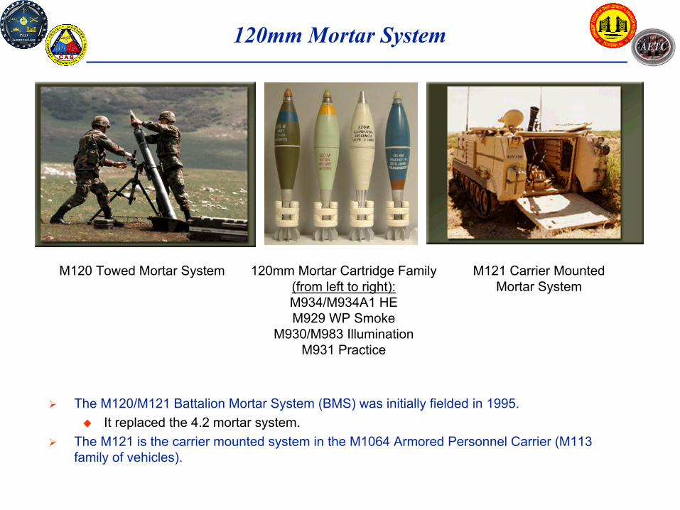
120mm Mortar System
The M120/M121 Battalion Mortar System (BMS) was initially fielded in 1995. It replaced the 4.2 mortar system.
The M121 is the carrier mounted system in the M1064 Armored Personnel Carrier (M113 family of vehicles).
M120 Towed Mortar System M121 Carrier Mounted Mortar System
120mm Mortar Cartridge Family (from left to right):M934/M934A1 HEM929 WP Smoke
M930/M983 IlluminationM931 Practice
120mm Mortar System
There are 3 primary methods for firing mortars:Predicted Fire – This method utilizes information about ammunition characteristics, weapon location, target location, and meteorological conditions to compute a ballistic solution for hitting the target. Observer Adjusted Fire – This method relies on having one or more Forward Observers within sight of the target area, to visually estimate how far the rounds miss the target and then provide feedback to the fire control unit, to reduce this error. Registration/Transfer – In this method one or more rounds are fired to a designated location for aiming purposes. Adjustments are made until the system error is reduced to an acceptable amount. Then these adjustments can then be “transferred” to hit other nearby targets more effectively.
4 rounds / minuteSustained Rate of Fire
16 rounds / minute (first minute)Maximum Rate of Fire
200 mMinimum Range
7,200 mMaximum Range
System Characteristics
Objectives of this Study
To provide examples of how the accuracy of the 120mm mortar system can be improved for evolutionary block upgrades or future programs such as the Stryker, Brigade Combat Team (BCT) or Future Combat System (FCS).
Reduction in the number of rounds required to hit the target.
Provide more accuracy for mortar fires, especially for coordinated fires from two or more mortars with different lots of ammo.
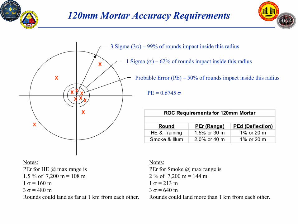
Probable Error (PE) – 50% of rounds impact inside this radius
1 Sigma (σ) – 62% of rounds impact inside this radius
3 Sigma (3σ) – 99% of rounds impact inside this radius
X
X
X
X
X
XXX
XX
Round PEr (Range) PEd (Deflection)HE & Training 1.5% or 30 m 1% or 20 mSmoke & Illum 2.0% or 40 m 1% or 20 m
ROC Requirements for 120mm Mortar
PE = 0.6745 σ
120mm Mortar Accuracy Requirements
Notes:PEr for Smoke @ max range is 2 % of 7,200 m = 144 m1 σ = 213 m3 σ = 640 m Rounds could land more than 1 km from each other.
Notes:PEr for HE @ max range is 1.5 % of 7,200 m = 108 m1 σ = 160 m3 σ = 480 m Rounds could land as far at 1 km from each other.
Precision vs Bias Errors
Fundamentally accuracy is described in terms of precision and bias. The mean point about which the rounds impact, is called the Mean Point of Impact (MPI). If the MPI is close to the center of the target, then the pattern is said to have a small MPI error or a small bias error.If the rounds impact very close to each, then the pattern is said to have a small precision error.
XXXXXXXXXX
X
X
XX
X
Good Precision & Good MPI
Good Precision but Poor MPI
Good MPI but Poor Precision
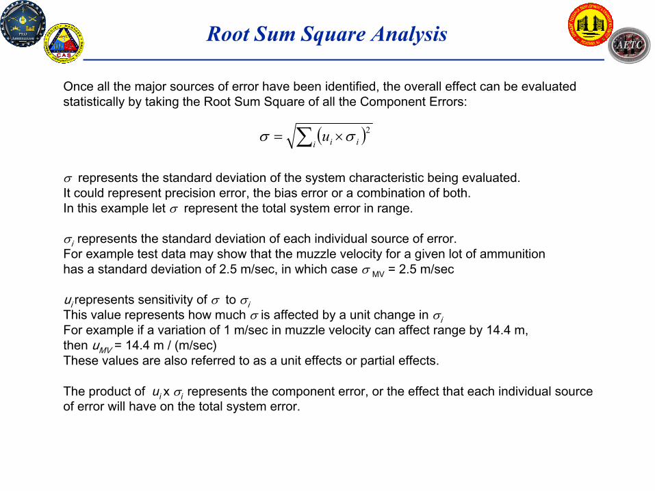
Root Sum Square Analysis
Once all the major sources of error have been identified, the overall effect can be evaluated statistically by taking the Root Sum Square of all the Component Errors:
σ represents the standard deviation of the system characteristic being evaluated.It could represent precision error, the bias error or a combination of both.In this example let σ represent the total system error in range.
σi represents the standard deviation of each individual source of error.For example test data may show that the muzzle velocity for a given lot of ammunition has a standard deviation of 2.5 m/sec, in which case σ MV = 2.5 m/sec
ui represents sensitivity of σ to σiThis value represents how much σ is affected by a unit change in σiFor example if a variation of 1 m/sec in muzzle velocity can affect range by 14.4 m, then uMV = 14.4 m / (m/sec)These values are also referred to as a unit effects or partial effects.
The product of ui x σi represents the component error, or the effect that each individual source of error will have on the total system error.
( )∑ ×=i iiu 2σσ
System Error Analysis
The effect of all the error components on the overall system error, is obtained by taking the root sum square of all the component errors. In this example the resulting system error in range will have a standard deviation of σ = 59.7 m. The 3σ error is 179.1m.
This means that with the given standard deviations and unit effects of all the individual sources of error, there is a 99% probability that the rounds will impact within 179.1 meters of the center of the target.
The unit effects and standard deviations used above, are representative nominal values for illustrative purposes.
Note that Muzzle Velocity and Meteorological conditions (Wind Velocity, Air Density and Air Temp) have the greatest affect on overall error.
Meteorological (MET) data is used to characterize the atmosphere that the mortar round will fly through. This includes:
Wind VelocityAir DensityAir Temperature
To illustrate how an improvement is MET accuracy can affect the total system accuracy, assume that MET could be improved at least 15%, by methods such as interfacing cost effective meteorological sensors with the on-board fire control system.
The resulting standard deviation in range would be reduced from 55.7 m to 51.1 m.Therefore the 15% reduction in MET error, reduced the total system error by 8.2%.
The following recommendations are offered, for future Fire Control System upgrades to help reduce the error associated with Meteorological (MET) uncertainty:
1. Wind Velocity Error Integrate a digital anemometer into the Fire Control System
2. Air Density Error Integrate a digital barometer into the Fire Control System
3. Air Temperature Error Integrate a digital thermometer into the Fire Control System
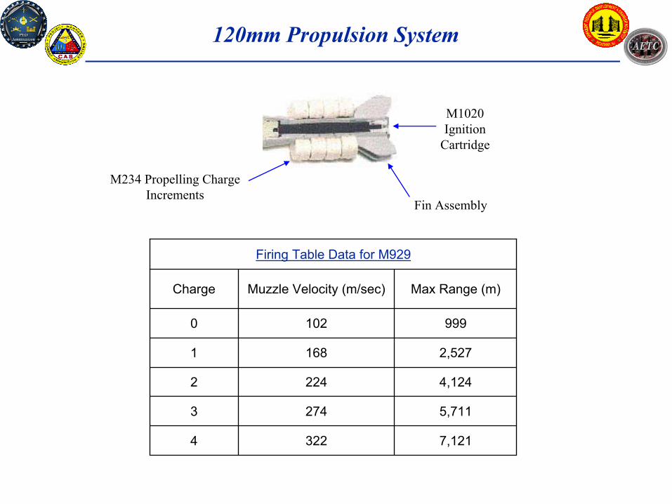
120mm Propulsion System
M1020 Ignition
Cartridge
Fin Assembly
Figure 1 - Propulsion System Components
M234 Propelling Charge Increments
7,121
5,711
4,124
2,527
999
Max Range (m)Muzzle Velocity (m/sec)Charge
3224
2743
2242
1681
1020
Firing Table Data for M929
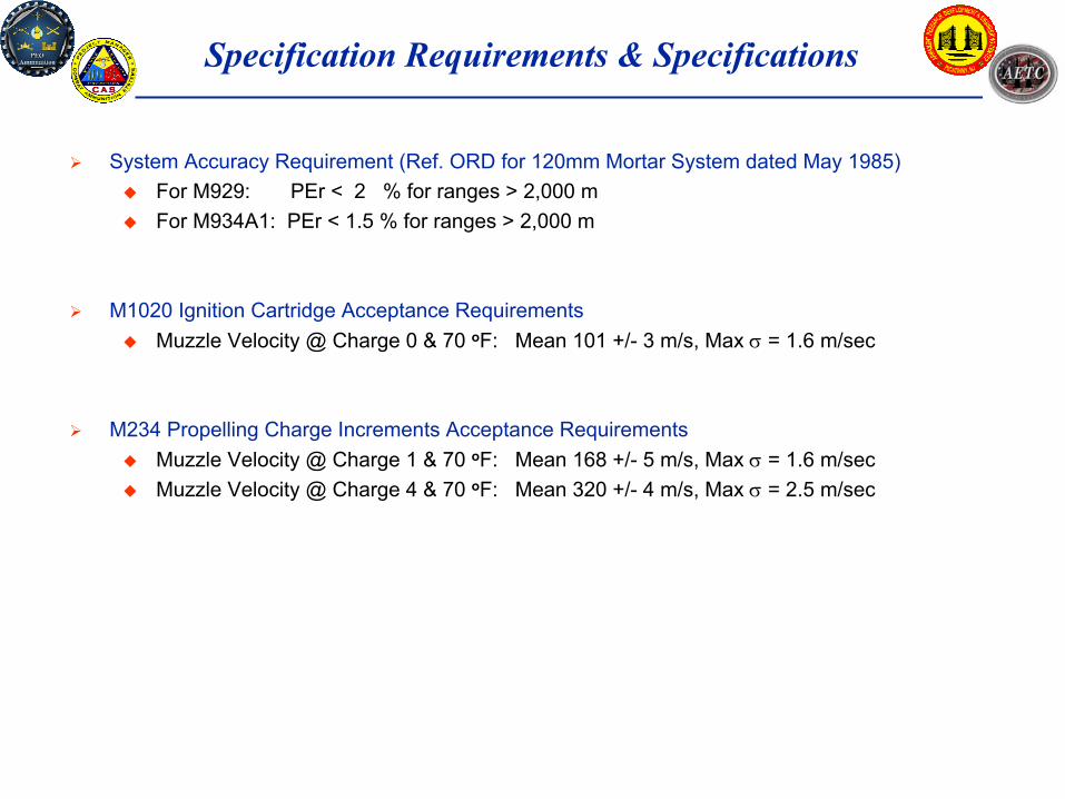
Specification Requirements & Specifications
System Accuracy Requirement (Ref. ORD for 120mm Mortar System dated May 1985)For M929: PEr < 2 % for ranges > 2,000 m For M934A1: PEr < 1.5 % for ranges > 2,000 m
M234 Propelling Charge Increments Acceptance RequirementsMuzzle Velocity @ Charge 1 & 70 oF: Mean 168 +/- 5 m/s, Max σ = 1.6 m/secMuzzle Velocity @ Charge 4 & 70 oF: Mean 320 +/- 4 m/s, Max σ = 2.5 m/sec
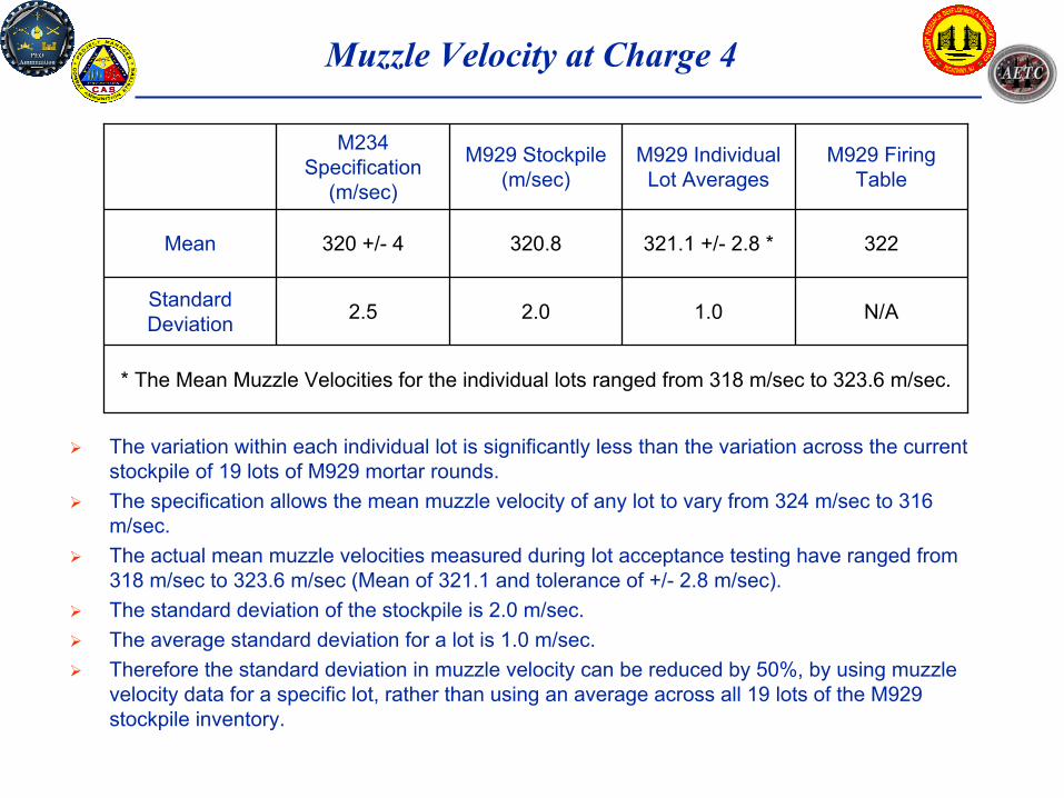
Muzzle Velocity at Charge 4
The variation within each individual lot is significantly less than the variation across the current stockpile of 19 lots of M929 mortar rounds. The specification allows the mean muzzle velocity of any lot to vary from 324 m/sec to 316 m/sec. The actual mean muzzle velocities measured during lot acceptance testing have ranged from 318 m/sec to 323.6 m/sec (Mean of 321.1 and tolerance of +/- 2.8 m/sec). The standard deviation of the stockpile is 2.0 m/sec. The average standard deviation for a lot is 1.0 m/sec. Therefore the standard deviation in muzzle velocity can be reduced by 50%, by using muzzle velocity data for a specific lot, rather than using an average across all 19 lots of the M929 stockpile inventory.
* The Mean Muzzle Velocities for the individual lots ranged from 318 m/sec to 323.6 m/sec.
N/A1.02.02.5Standard Deviation
322321.1 +/- 2.8 *320.8320 +/- 4Mean
M929 Firing Table
M929 Individual Lot Averages
M929 Stockpile (m/sec)
M234 Specification
(m/sec)
Effects of Muzzle Velocity Improvement
Reducing the standard deviation of muzzle velocity from 2 m/sec to 1 m/sec, reduces the total system standard deviation is from 55.7 m to 49.8 m. Therefore reducing the standard deviation of muzzle velocity by 50%, reduces the total system error by 10.6%.
The following recommendations are offered for Future Fire Control Software upgrades to help reduce the error associated with Muzzle Velocity uncertainty:
1. Incorporate lot specific propulsion system data into the Fire Control software to improve the accuracy of the ballistic solution
Muzzle velocity data is already being collected, for each lot of ammunition, during various life cycle tests, such as:
Lot Acceptance Testing (LAT)Stockpile Surveillance TestingFiring Tables Updates
2. Measure actual propellant temp and input into the Fire Control SystemThe muzzle velocity is very sensitive to the temperature of the propellantThe Firing Tables include corrections to adjust the expected Muzzle Velocity based on the temperature of the propellantThe temperature of the propellant in the packaged configuration, could be significantly different from the ambient air temperature.
Providing an inexpensive means to measure the temperature of the propelling charge increments, would reduce the the Muzzle Velocity error.
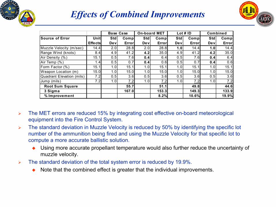
Effects of Combined Improvements
The MET errors are reduced 15% by integrating cost effective on-board meteorological equipment into the Fire Control System. The standard deviation in Muzzle Velocity is reduced by 50% by identifying the specific lot number of the ammunition being fired and using the Muzzle Velocity for that specific lot to compute a more accurate ballistic solution.
Using more accurate propellant temperature would also further reduce the uncertainty of muzzle velocity.
The standard deviation of the total system error is reduced by 19.9%. Note that the combined effect is greater that the individual improvements.
The objectives of this study were:To identify how its accuracy can be improved to meet future requirements such as the block upgrades for the Brigade Combat Team (BCT) and the Future Combat System (FCS). To provide an estimate of how much the system accuracy can be improvement by the recommendations made.
The ballistic trajectory will be significantly affected by the meteorological conditions, such as wind velocity, air temperature and air density.
Methods for reducing the uncertainty of meteorological data include interfacing electronic instruments into the fire control system for measuring the temperature, humidity and wind velocity and the gun location.
Another significant source of error is the uncertainty associate with the muzzle velocity of the round when it leaves the weapon. The muzzle velocity error is a function of the variability of the propulsion system components and the temperature of the propellant when fired.
The variability in propulsion system components can be reduced by using muzzle velocity data on each production lot of mortar rounds which is being collected during life cycle tests such as lot acceptance testing and stockpile surveillance testing. More accurate measurement of the propellant temperature would further reduce the errors associated muzzle velocity.
The combined effects of these recommendations, are estimated to improve the system accuracy by as much as 20%.