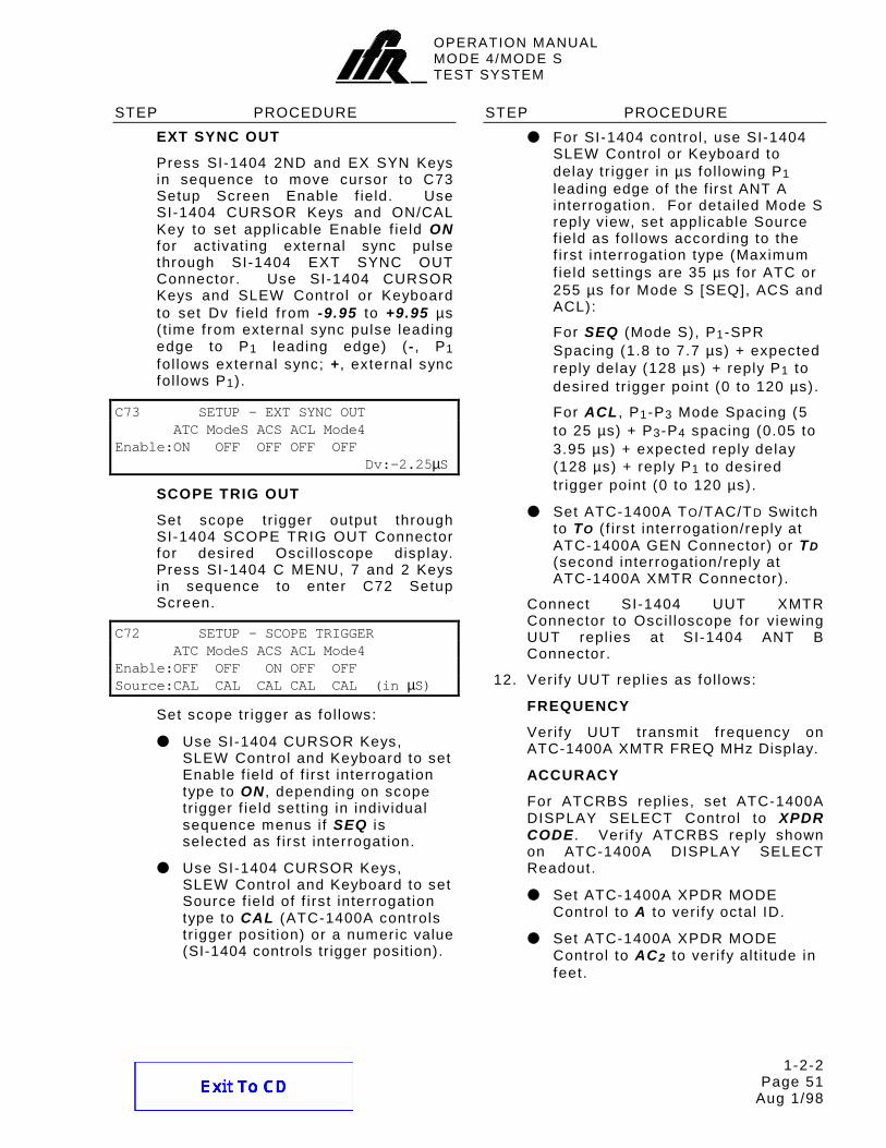
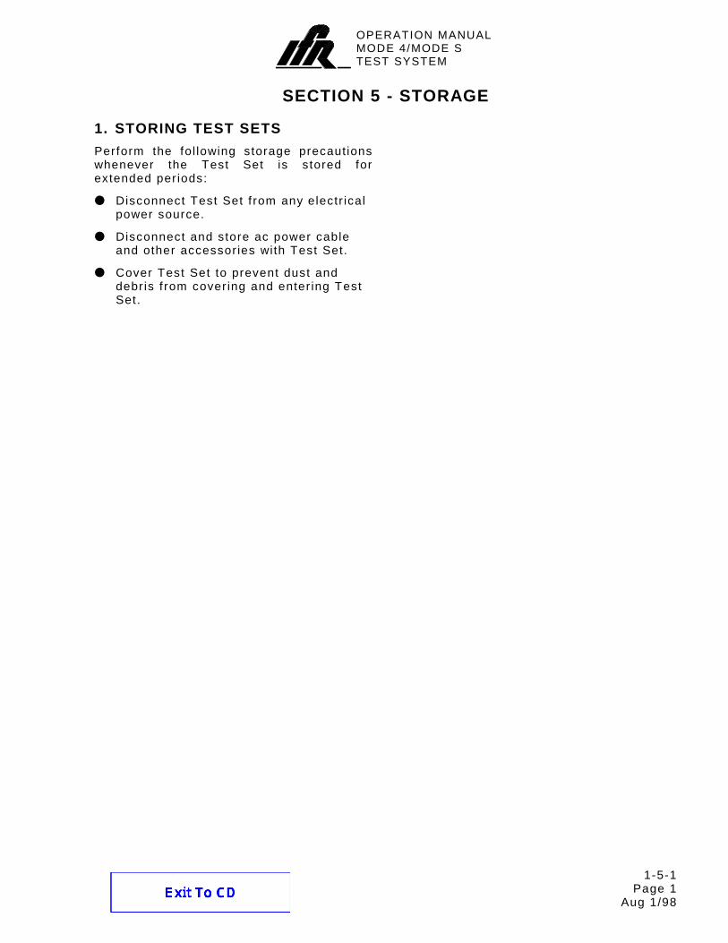
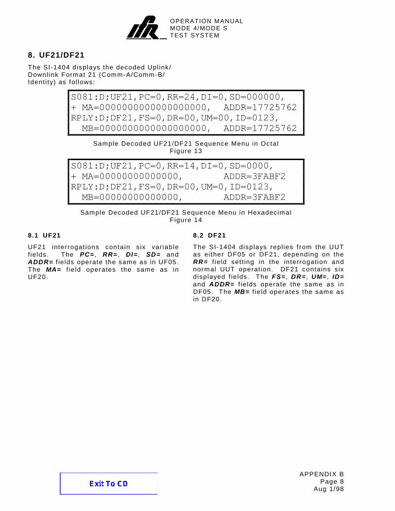
MODE 4/MODE S TEST SYSTEM SI-1404 I I 0 0 0 0 0 0 0 0 0 0 + 0 0 0 0 0 0 0 0 OFF 0 0 0 0 0 0 0 OFF 0 0 0 0 XPDR DME DIST XPDR VEL RANGE FREQ PRF SQTR Hz DISPLAY SELECT DME REPLY EFFICIENCY 50 0 10 20 30 40 100 60 70 80 90 B C D AC AC 1 2 CODE FEET 1 2 T A TACAN ON OFF IDENT CODE TONE OFF 2 2 F /P P / F 1 1 DISCRIMINATOR INTRF PULSE WIDTH DBL INTERR / INTRF PULSE PRF/SQTR XPDR P /P DEV 2 3 ON OFF P P P CAL CAL CAL 2 3 2 V V V V V V V - + + - + - DME P DEV 2 T TO D TAC SYNC 1.0 S 1.45 S CAL MARKS CAL O / AUTO MAN MAN STEP OFF FREQ STEP RATE VAR CAL XPDR PULSE WIDTH SLS/ECHO ON OFF ON OFF SUPPRESSOR VAR FREQ / FUNCTION SELECT F DME-PRF XPDR-% Hz REPLY XMTR FREQ XMTR PWR UNIT UNDER TEST MHz WATTS RF LEVEL -dBm CW NORM OFF RF I/O XXX.XX RNG XXX0.0 XXX.00 VEL ACCEL NMi KTS FT/S/S L O A D C L E A R IN -1 NMi OUT NORM GEN XMTR RANGE/VEL/ACCEL ATC- 1400A XPDR MODE PPMG EX MOD ON/CAL CL/ESC C MENU SEQ AD P PULS EX SYN +/- 0 S MENU ANT B SAVE RECALL 3 2 1 BURST 7/D 2ND 8/E 9/F P3 P2 FUNC# ARF LVL 4/A 5/B 6/C SPR P4/P6 HEX CURSOR SLEW POWER BRIGHTNESS BRF LVL PRTSCR U MENU T MENU HELP ENTER POWER 1kW PK 10W AVG ANT B UUT VIDEO NMi CODE KTS NMi MHz SI-1404 Operation Manual 1002-2401-200
Transcript
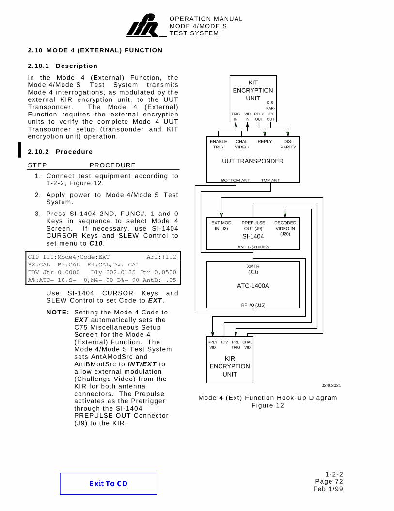
MODE 4/MODE S TEST SYSTEM
SI-1404
I
I
0000 000 000 + 00 0
00 0 0 0OFF000 0 00 0 OFF00 0 0 XPDR
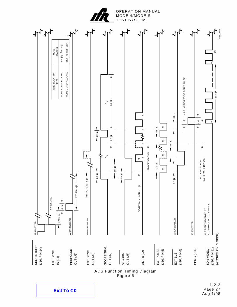
DME DIST
XPDR
VEL
RANGE
FREQ
PRF SQTR Hz
DISPLAY SELECT
DME REPLY
EFFICIENCY
50
0
10
20
30
40
100
60
70
80
90
BC
D
AC
AC
1
2
CODE
FEET1
2
T
A
TACAN
ON OFF
IDENT
CODETONE
OFF
2 2F / P P/F
11
DISCRIMINATOR
INTRF
PULSE WIDTH
DBL INTERR / INTRF PULSE
PRF/SQTR XPDR P /P DEV2 3
ON OFF
P P P
CAL CAL CAL
2 3 2
VV V V VV
V
- ++ - + -
DME P DEV2
TT O D
TAC
SYNC
1.0 S 1.45 S
CAL MARKSCAL O/
AUTO
MANMAN
STEP
OFF
FREQ
STEP
RATE
VAR CAL
XPDR PULSE WIDTH SLS/ECHO
ON OFF
ON OFF
SUPPRESSOR
VAR
FREQ / FUNCTION SELECT F
DME-PRF
XPDR-%
Hz
REPLY XMTR FREQ XMTR PWR
UNIT UNDER TEST
MHz WATTS
RF LEVEL
-dBm
CW
NORM
OFF
RF I/O
XXX.XX
RNG
XXX0.0 XXX.00
VEL ACCEL
NMi KTS FT/S/S
L
O
A
D
C
L
E
A
R
IN -1 NMi
OUT NORM
GEN XMTR
RANGE/VEL/ACCEL
ATC-1400A
XPDR MODE
PPMG EX MOD
ON/CALCL/ESCC MENU
SEQ AD P PULS EX SYN
+/-0S MENU
ANT B SAVE RECALL
321BURST
7/D
2ND
8/E 9/F
P3P2FUNC#
ARF LVL 4/A 5/B 6/C
SPRP4/P6HEX
CURSOR
SLEW
POWER
BRIGHTNESS
BRF LVL
PRTSCR
U MENU
T MENU HELP
ENTER
POWER
1kW PK
10W AVG
ANT B
UUT VIDEO
NMi
CODE
KTS
NMi
MHz
SI-1404
Operation Manual 1002-2401-200
OPERATION MANUAL
MODE 4/MODE S TEST SYSTEM
SI-1404
PUBLISHED BY
IFR AMERICAS, INC.
COPYRIGHT IFR Americas, Inc. 1998 Al l r ights reserved. No part of this publ icat ion may be reproduced, stored in a retr ieval system, or transmitted in any form or by any means, electronic, mechanical, photocopying, recording or otherwise without the pr ior permission of the publ isher.
10200 W est York / W ichita, Kansas 67215 U.S.A. / (316) 522-4981 / FAX 524-2623
OPERATION MANUALMODE 4/MODE STEST SYSTEM
THIS PAGE INTENTIONALLY LEFT BLANK.
OPERATION MANUALMODE 4/MODE STEST SYSTEM
Cable Statement: Double shielded and properly terminated external interface cables must be used with this equipment when interfacing with the RS-232, GPIB, IFR BUS and/or AUX BUS Connectors. Nomenclature Statements: In this manual the SI-1404, SI-1404 Test Auxiliary, Test Auxiliary or Test Set refers to the SI-1404 Test Auxiliary. In this manual the ATC-1400A, ATC-1400A Transponder/DME Test Set or ATC-1400A Test Set refers to the ATC-1400A-2 Transponder/DME Test Set.
OPERATION MANUALMODE 4/MODE STEST SYSTEM
THIS PAGE INTENTIONALLY LEFT BLANK.
OPERATION MANUALMODE 4/MODE STEST SYSTEM
SAFETY FIRST: TO ALL OPERATIONS PERSONNEL REFER ALL SERVICING OF UNIT TO QUALIFIED TECHNICAL PERSONNEL. THIS UNIT CONTAINS NO OPERATOR SERVICEABLE PARTS.
W ARNING: USING THIS EQUIPMENT IN A MANNER NOT SPECIF IED BY THE ACCOMPANYING DOCUMENTATION MAY IMPAIR THE SAFETY PROTECTION PROVIDED BY THE EQUIPMENT.
CASE, COVER OR PANEL REMOVAL
Removing pro tec t i ve covers , cas ings or pane ls f rom th is Tes t Set exposes the operator to e lec t r i ca l hazards that can resu l t in e lec t r i ca l shock or equ ipment damage. Do not operate th is Tes t Set wi th the case, cover or pane ls removed.
SAFETY IDENTIFICATION IN TECHNICAL MANUAL
This manual uses the fo l lowing terms to draw at tent ion to poss ib le safe ty hazards , that may exis t when operat ing th is equ ipment .
CAUTION: THIS TERM IDENTIF IES CONDITIONS OR ACTIVIT IES THAT, IF IGNORED, CAN RESULT IN EQUIPMENT OR PROPERTY DAMAGE (E .G. , F IRE) .
W ARNING: THIS TERM IDENTIFIES CONDITIONS OR ACTIVITIES THAT, IF IGNORED, CAN RESULT IN PERSONAL INJURY OR DEATH.
SAFETY SYMBOLS IN MANUALS AND ON UNITS
CAUTION: Refer to accompany ing documents . (Th is symbol re fers to spec i f i c CAUTIONS represented on the un i t and c lar i f ied in the text . )
AC OR DC TERMINAL: Term ina l that may supp ly or be supp l ied wi th ac or dc vo l tage.
DC TERMINAL: Term ina l that may supp ly or be supp l ied wi th dc vo l tage.
AC TERMINAL: Term ina l that may supp ly or be supp l ied wi th ac or a l te rnat ing vo l tage.
SW ITCH OFF: AC l ine power to the dev ice i s OFF.
SW ITCH ON: AC l ine power to the dev ice i s ON.
EQUIPMENT GROUNDING PRECAUTION
Improper ground ing o f equ ipment can resu l t in e lec t r i ca l shock .
USE OF PROBES
Check spec i f i ca t ions for the maximum vo l tage, cur rent and power ra t ings o f any connec tor on the Tes t Set before connec t ing i t wi th a probe f rom a term ina l dev ice. Be sure the term ina l dev ice per forms wi th in these spec i f i ca t ions before us ing i t fo r measurement , to prevent e lec t r i ca l shock or damage to the equ ipment .
POW ER CORDS
Power cords mus t not be f rayed, broken nor expose bare wi r ing when operat ing th is equ ipment .
USE RECOMMENDED FUSES ONLY
Use on ly fuses spec i f i ca l l y recommended for the equ ipment a t the spec i f ied cur rent and vo l tage ra t ings .
INTERNAL BATTERY
This un i t conta ins a L i th ium Bat tery , serv iceab le on ly by a qua l i f ied techn ic ian.
CAUTION: S IGNAL GENERATORS CAN BE A SOURCE OF ELECTROMAGNETIC INTERFERENCE (EMI ) TO COMMUNICATION RECEIVERS. SOME TRANSMITTED SIGNALS CAN CAUSE DISRUPTION AND INTERFERENCE TO COMMUNICATION SERVICES OUT TO A DISTANCE OF SEVERAL MILES. USERS OF THIS EQUIPMENT SHOULD SCRUTINIZE ANY OPERATION THAT RESULTS IN RADIATION OF A S IGNAL (DIRECTLY OR INDIRECTLY) AND SHOULD TAKE NECESSARY PRECAUTIONS TO AVOID POTENTIAL COMMUNICATION INTERFERENCE PROBLEMS.
OPERATION MANUALMODE 4/MODE STEST SYSTEM
THIS PAGE INTENTIONALLY LEFT BLANK.
OPERATION MANUALMODE 4/MODE STEST SYSTEM
RECORD OF REVISIONS
REV NO.
ISSUE DATE
DATE INSERTED
BY
REV NO.
ISSUE DATE
DATE INSERTED
BY
01 2-1-99
OPERATION MANUALMODE 4/MODE STEST SYSTEM
THIS PAGE INTENTIONALLY LEFT BLANK.
OPERATION MANUALMODE 4/MODE STEST SYSTEM
LIST OF EFFECTIVE PAGES Page 1
Feb 1/99
LIST OF EFFECTIVE PAGES
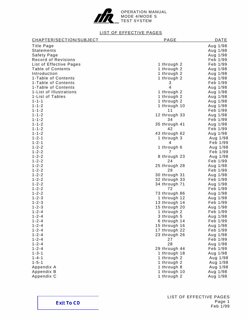
CHAPTER/SECTION/SUBJECT PAGE DATE Tit le Page Aug 1/98 Statements Aug 1/98 Safety Page Aug 1/98 Record of Revis ions Feb 1/99 List of Ef fect ive Pages 1 through 2 Feb 1/99 Table of Contents 1 through 2 Aug 1/98 Introduct ion 1 through 2 Aug 1/98 1-Table of Contents 1 through 2 Aug 1/98 1-Table of Contents 3 Feb 1/99 1-Table of Contents 4 Aug 1/98 1-List of I l lustrat ions 1 through 2 Aug 1/98 1-List of Tables 1 through 2 Aug 1/98 1-1-1 1 through 2 Aug 1/98 1-1-2 1 through 10 Aug 1/98 1-1-2 11 Feb 1/99 1-1-2 12 through 33 Aug 1/98 1-1-2 34 Feb 1/99 1-1-2 35 through 41 Aug 1/98 1-1-2 42 Feb 1/99 1-1-2 43 through 62 Aug 1/98 1-2-1 1 through 3 Aug 1/98 1-2-1 4 Feb 1/99 1-2-2 1 through 6 Aug 1/98 1-2-2 7 Feb 1/99 1-2-2 8 through 23 Aug 1/98 1-2-2 24 Feb 1/99 1-2-2 25 through 28 Aug 1/98 1-2-2 29 Feb 1/99 1-2-2 30 through 31 Aug 1/98 1-2-2 32 through 33 Feb 1/99 1-2-2 34 through 71 Aug 1/98 1-2-2 72 Feb 1/99 1-2-2 73 through 86 Aug 1/98 1-2-3 1 through 12 Aug 1/98 1-2-3 13 through 14 Feb 1/99 1-2-3 15 through 20 Aug 1/98 1-2-4 1 through 2 Feb 1/99 1-2-4 3 through 5 Aug 1/98 1-2-4 6 through 14 Feb 1/99 1-2-4 15 through 16 Aug 1/98 1-2-4 17 through 22 Feb 1/99 1-2-4 23 through 26 Aug 1/98 1-2-4 27 Feb 1/99 1-2-4 28 Aug 1/98 1-2-4 29 through 44 Feb 1/99 1-3-1 1 through 18 Aug 1/98 1-4-1 1 through 2 Aug 1/98 1-5-1 1 through 2 Aug 1/98 Appendix A 1 through 8 Aug 1/98 Appendix B 1 through 10 Aug 1/98 Appendix C 1 through 2 Aug 1/98
OPERATION MANUALMODE 4/MODE STEST SYSTEM
LIST OF EFFECTIVE PAGES Page 2
Feb 1/99
Chapter/Sect ion/Subject Page Date
Appendix D 1 Feb 1/99 Appendix D 2 through 19 Aug 1/98 Appendix D 20 through 22 Feb 1/99 Appendix E 1 through 5 Aug 1/98 Appendix E 6 Feb 1/99 Appendix F 1 Feb 1/99 Appendix F 2 Aug 1/98 Appendix G 1 through 2 Aug 1/98 Appendix H 1 through 2 Aug 1/98 Appendix I 1 through 6 Aug 1/98 Index 1 Aug 1/98 Index 2 Feb 1/99 Index 3 through 4 Aug 1/98 Index 5 Feb 1/99 Index 6 Aug 1/98 Instal lat ion Cal ibrat ion Procedure T it le Page Aug 1/98 Instal lat ion Cal ibrat ion Procedure W arning Page Aug 1/98 Instal lat ion Cal ibrat ion Procedure Caution Page Aug 1/98 Instal lat ion Cal ibrat ion Procedure 1 Aug 1/98 Instal lat ion Cal ibrat ion Procedure 2 Feb 1 99 Instal lat ion Cal ibrat ion Procedure 3 through 9 Aug 1/98 Instal lat ion Cal ibrat ion Procedure 10 Feb 1/99 Instal lat ion Cal ibrat ion Procedure 11 Aug 1/98 Instal lat ion Cal ibrat ion Procedure 12 through 14 Feb 1/99
OPERATION MANUALMODE 4/MODE STEST SYSTEM
TABLE OF CONTENTS Page 1
Aug 1/98
TABLE OF CONTENTS
Tit le Chapter/Sect ion
T it le Page Copyr ight Page Statements Safety Page Record of Revis ions List of Ef fect ive Pages Table of Contents Introduct ion
Chapter 1
Sect ion 1 - Descr ipt ion 1-1 Sect ion 2 - Operat ion 1-2 Sect ion 3 - Specif icat ions 1-3 Sect ion 4 - Shipping 1-4 Sect ion 5 - Storage 1-5
Appendix A - Connector Pin-Out Tables Appendix B - Decoded Sequence Menu Formats Appendix C - Test Equipment Requirements Appendix D - Mode S Signal Formats Appendix E - Interrogat ion and Reply T iming Appendix F - Mode 4 Interrogat ion W ord Format Code Posit ion Chart Appendix G - Related Documents Appendix H - Metr ic /Br i t ish Imper ial Conversion Table with Nautical Distance Conversions Appendix I - Abbreviat ions
Index
Instal lat ion Cal ibrat ion Procedure
OPERATION MANUALMODE 4/MODE STEST SYSTEM
TABLE OF CONTENTS Page 2
Aug 1/98
THIS PAGE INTENTIONALLY LEFT BLANK.
OPERATION MANUALMODE 4/MODE STEST SYSTEM
INTRODUCTION Page 1
Aug 1/98
INTRODUCTION - MODE 4/MODE S TEST SYSTEM
This manual contains the information necessary to instal l and operate the Mode 4/Mode S Test System. I t is designed to be used in conjunct ion with the ATC-1400A Operat ion Manual. The SI-1404 Test Auxi l iary, when interfaced with the ATC-1400A Transponder/DME Test Set, forms the Mode 4/Mode S Test System. The addit ional remote commands required for ATCRBS, Mode 4 and Mode S test ing are l is ted in Sect ion 1-2-4 of this manual.
I t is strongly recommended that personnel be thoroughly famil iar with the contents of this manual, along with contents of the ATC-1400A Operat ion Manual, before attempting to operate this equipment.
Refer al l servic ing of the Mode 4/Mode S Test System to qual i f ied technical personnel.
ORGANIZATION
This manual is divided into the fol lowing Chapters and Sect ions:
CHAPTER 1 - OPERATION
Sect ion 1 - DESCRIPTION (physical descr ipt ion of the SI-1404; descr ipt ion of controls, connectors and indicators and menus and screens)
Sect ion 2 - OPERATION ( instal lat ion; general operat ing procedures, performance evaluat ion, remote operat ion)
Sect ion 3 - SPECIFICATIONS
Sect ion 4 - SHIPPING
Sect ion 5 - STORAGE
OPERATION MANUALMODE 4/MODE STEST SYSTEM
INTRODUCTION Page 2
Aug 1/98
THIS PAGE INTENTIONALLY LEFT BLANK.
OPERATION MANUALMODE 4/MODE STEST SYSTEM
1-TABLE OF CONTENTS Page 1
Aug 1/98
CHAPTER ONE
MODE 4/MODE S TEST SYSTEM
OPERATION MANUAL
TABLE OF CONTENTS
T it le Chapter/Sect ion/Subject Page
SECTION 1 - DESCRIPTION 1-1 1. General Descr ipt ion and Capabi l i t ies 1-1-1 1 1.1 Descr ipt ion 1-1-1 1 1.2 Funct ional Capabi l i t ies 1-1-1 1 2. Controls, Connectors and Indicators 1-1-2 2 2.1 SI-1404 Front Panel 1-1-2 4 2.2 SI-1404 Rear Panel 1-1-2 5 2.3 Keyboard Def ini t ion 1-1-2 9 2.4 Display Menu Def ini t ion 1-1-2 13
2.4.1 Control Menus (CMENU) 1-1-2 14 2.4.2 Sequence Menus (SMENU) 1-1-2 43 2.4.3 Test Menus (TMENU) 1-1-2 46
2.5 ATC-1400A Front Panel 1-1-2 56 2.6 ATC-1400A Rear Panel 1-1-2 62 SECTION 2 - OPERATION 1-2 1. Instal lat ion 1-2-1 1 1.1 General 1-2-1 1 1.2 Safety Precautions 1-2-1 1
1.2.1 Complying W ith Instruct ions 1-2-1 1 1.2.2 Grounding Equipment and Power Cord 1-2-1 1 1.2.3 Operat ing Safety 1-2-1 1 1.2.4 CAUTION and W ARNING Labels 1-2-1 1
1.3 Power Requirements 1-2-1 2 1.4 Instal lat ion Procedure 1-2-1 2 1.5 Power-Up Procedure 1-2-1 4 1.6 Instal lat ion Cal ibrat ion 1-2-1 4 1.7 External Cleaning 1-2-1 4 2. General Operat ing Procedures 1-2-2 1 2.1 General 1-2-2 1
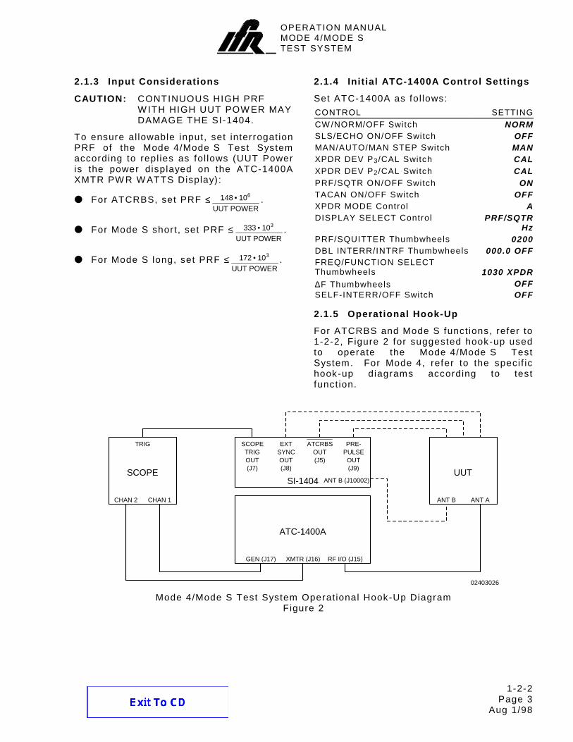
2.1.1 System Character ist ics 1-2-2 1 2.1.2 System Considerat ions 1-2-2 2 2.1.3 Input Considerat ions 1-2-2 3 2.1.4 Ini t ial ATC-1400A Control Sett ings 1-2-2 3 2.1.5 Operat ional Hook-Up 1-2-2 3
2.2 ATC Funct ion 1-2-2 4 2.2.1 Descr ipt ion 1-2-2 4 2.2.2 Procedure 1-2-2 4 2.2.3 General Test Sequence 1-2-2 9
2.3 SEQ Funct ion 1-2-2 12 2.3.1 Descr ipt ion 1-2-2 12 2.3.2 Procedure 1-2-2 12 2.3.3 General Test Sequence 1-2-2 18
OPERATION MANUALMODE 4/MODE STEST SYSTEM
1-TABLE OF CONTENTS Page 2
Aug 1/98
T it le Chapter/Sect ion/Subject Page 2.4 ACS Funct ion 1-2-2 21
2.4.1 Descr ipt ion 1-2-2 21 2.4.2 Procedure 1-2-2 21 2.4.3 General Test Sequence 1-2-2 26
2.5 ACL Funct ion 1-2-2 29 2.5.1 Descr ipt ion 1-2-2 29 2.5.2 Procedure 1-2-2 29 2.5.3 General Test Sequence 1-2-2 34
2.6 INTLCE Funct ion 1-2-2 37 2.6.1 Descr ipt ion 1-2-2 37 2.6.2 Procedure 1-2-2 38 2.6.3 General Test Sequence 1-2-2 43
2.7 DI Funct ion 1-2-2 46 2.7.1 Descr ipt ion 1-2-2 46 2.7.2 Procedure 1-2-2 46 2.7.3 General Test Sequence 1-2-2 54
2.8 Burst Funct ion 1-2-2 57 2.8.1 Descr ipt ion 1-2-2 57 2.8.2 Procedure 1-2-2 57
2.9 Mode 4 ( Internal) Funct ion 1-2-2 64 2.9.1 Descr ipt ion 1-2-2 64 2.9.2 Procedure 1-2-2 64 2.9.3 General Test Sequence 1-2-2 69
2.10 Mode 4 (External) Funct ion 1-2-2 72 2.10.1 Descr ipt ion 1-2-2 72 2.10.2 Procedure 1-2-2 72 2.10.3 General Test Sequence 1-2-2 74
2.11 Test Menu Tests 1-2-2 76 2.11.1 MTL Test 1-2-2 76 2.11.2 ELM Tests 1-2-2 78
2.12 Memory Operat ion 1-2-2 85 2.12.1 Save 1-2-2 85 2.12.2 Recal l 1-2-2 85
2.13 Pr int Screen 1-2-2 86 2.14 Stand Alone Operat ion 1-2-2 86 3. Performance Evaluat ion 1-2-3 1 3.1 General 1-2-3 1 3.2 Pre-Operat ional Condit ions 1-2-3 1 3.3 Test Equipment Requirements 1-2-3 1 3.4 Correct ive Maintenance 1-2-3 1 3.5 Test Record 1-2-3 1 3.6 Performance Evaluat ion Procedure 1-2-3 1 3.7 Performance Evaluat ion Data Sheet 1-2-3 16
OPERATION MANUALMODE 4/MODE STEST SYSTEM
1-TABLE OF CONTENTS Page 3
Feb 1/99
T it le Chapter/Sect ion/Subject 4. Remote Operat ion 1-2-4 1 4.1 General 1-2-4 1 4.2 Front Panel Operat ion 1-2-4 1 4.3 Operat ing Procedures 1-2-4 1
4.3.1 ATC-1400A GPIB Conf igurat ion 1-2-4 1 4.3.2 SI-1404 RS-232 Conf igurat ion 1-2-4 2 4.3.3 SI-1404 GPIB Conf igurat ion 1-2-4 3
4.4 Test Macro Language (TMAC) 1-2-4 4 4.5 Command Syntax 1-2-4 4 4.6 Commands 1-2-4 5 4.7 Examples 1-2-4 40
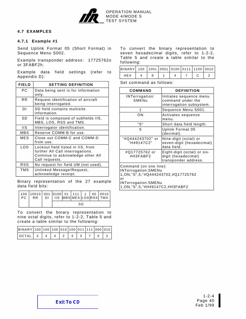
4.7.1 Example #1 1-2-4 40 4.7.2 Example #2 1-2-4 41 4.7.3 Example #3 1-2-4 43 4.7.4 Example #4 1-2-4 44
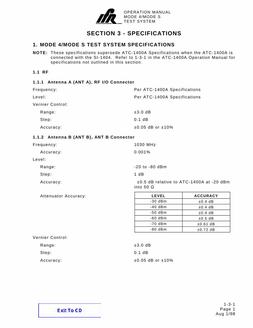
SECTION 3 - SPECIFICATIONS 1-3 1. Mode 4/Mode S Test System Specif icat ions 1-3-1 1 1.1 RF 1-3-1 1
1.1.1 Antenna A (ANT A), RF I /O Connector 1-3-1 1 1.1.2 Antenna B (ANT B), ANT B Connector 1-3-1 1
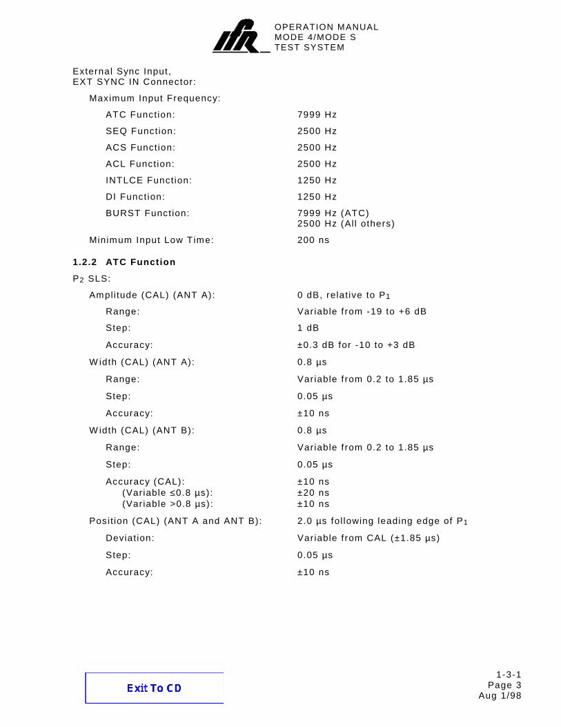
1.2 Pulse Character ist ics 1-3-1 2 1.2.1 General 1-3-1 2 1.2.2 ATC Funct ion 1-3-1 3 1.2.3 SEQ Funct ion 1-3-1 6 1.2.4 ACS/ACL Funct ions 1-3-1 8 1.2.5 INTLCE Funct ion 1-3-1 9 1.2.6 DI Funct ion 1-3-1 9 1.2.7 BURST Funct ion 1-3-1 9 1.2.8 ELM Funct ion 1-3-1 9 1.2.9 Mode 4 ( Internal) Funct ion 1-3-1 10 1.2.10 Mode 4 (External) Funct ion 1-3-1 13
1.3 UUT Measurements 1-3-1 13 1.3.1 Reply Delay 1-3-1 13 1.3.2 %Reply 1-3-1 15 1.3.3 Pulse Character ist ics 1-3-1 `15 1.3.4 Mode 4 TDV Jit ter 1-3-1 16
1.5 Power Requirements 1-3-1 18 1.6 Fuse Requirements 1-3-1 18 1.7 Safety Condit ions 1-3-1 18 SECTION 4 - SHIPPING 1-4 1. Shipping Test Sets 1-4-1 1 1.1 Information 1-4-1 1 1.2 Repack ing Procedure 1-4-1 1 SECTION 5 - STORAGE 1-5 1. Stor ing Test Sets 1-5-1 1
OPERATION MANUALMODE 4/MODE STEST SYSTEM
1-TABLE OF CONTENTS Page 4
Aug 1/98
THIS PAGE INTENTIONALLY LEFT BLANK.
OPERATION MANUALMODE 4/MODE STEST SYSTEM
1-LIST OF ILLUSTRATIONS Page 1
Aug 1/98
LIST OF ILLUSTRATIONS
T it le Chapter/Sect ion/Subject Page SI-1404 Front and Rear Panels 1-1-2 2 SI-1404 Keyboard 1-1-2 9 Example Save and Recal l Conf igurat ion Screens 1-1-2 11 Main Control Menu 1-1-2 14 Example Funct ion A ATC Screens 1-1-2 14 Example Funct ion A SEQ Screen 1-1-2 16 Example Funct ion A ACS Screen 1-1-2 17 Example Funct ion A ACL Screen 1-1-2 17 Example Funct ion A Inter lace Screen 1-1-2 18 Example Funct ion A Double Interrogation Screen 1-1-2 19 Example Funct ion A Burst Screen 1-1-2 20 Example Funct ion A ATC Monitor Screen 1-1-2 21 Example Funct ion A Mode 4 Screen 1-1-2 22 Example Funct ion A Mode 4 Monitor Screen 1-1-2 24 Example Funct ion B Screens 1-1-2 25 Example Percent Reply Screen 1-1-2 26 Example Reply Delay Screen 1-1-2 27 Example Squit ter (1 of 2) Screen 1-1-2 28 Example Squit ter (2 of 2) Screen 1-1-2 29 Main Setup Menu 1-1-2 30 Example C71 Setup ( Interrogat ion Tr igger) Screen 1-1-2 30 Example C72 Setup (Scope Tr igger) Screen 1-1-2 31 Example C73 Setup (Ext Sync Out) Screen 1-1-2 32 Example C74 Setup (PPMG) Screen 1-1-2 33 Example C75 Setup (Misc) Screen 1-1-2 34 Example C76 Setup (SMenu) Screen 1-1-2 35 Example C78 Setup (Mode 4) Screen 1-1-2 36 Example C79 Setup (ATC1400A Controls) Screen 1-1-2 38 Main System Menu 1-1-2 39 Example C81 System (RS232 Control) Screen 1-1-2 39 Example C82 System (RS232 Interface) Screen 1-1-2 40 Example C83 System (GPIB) Screen 1-1-2 40 Example C84 System (IFR BUS) Screen 1-1-2 41 Example C85 System (Keyboard) Screen 1-1-2 41 Example C86 System (Clock) Screen 1-1-2 42 Example C89 System (Version) Screen 1-1-2 42 S Format Sequence Menu Examples in Octal and Hex Radix 1-1-2 43 L Format Sequence Menu Examples in Octal and Hex Radix 1-1-2 43 D Format Sequence Menu Examples in Octal and Hex Radix 1-1-2 44 Sequence Menu Interrogat ion AP Field Formation 1-1-2 45 Main Test Menu 1-1-2 46 Example Miscel laneous Test Menu 1-1-2 46 Example T23 Miscel laneous MTL Screen 1-1-2 47 Example ELM Test Menu 1-1-2 47 Example T31 ELM Setup Screen 1-1-2 48 Example T32 UELM Test Screen 1-1-2 49 Example T33 UELM-Mult i Test Screen 1-1-2 50 Example T34 DELM Test Screen 1-1-2 51
OPERATION MANUALMODE 4/MODE STEST SYSTEM
1-LIST OF ILLUSTRATIONS Page 2
Aug 1/98
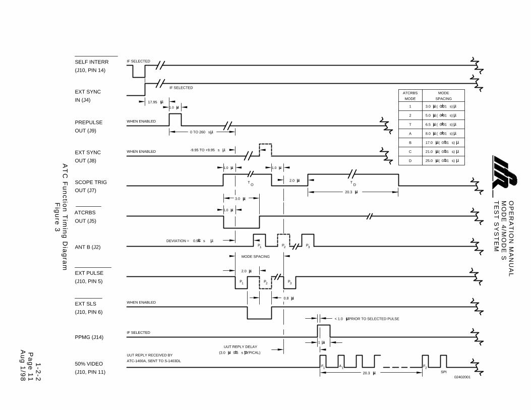
T it le Chapter/Sect ion/Subject Page Example T35 DELM-Mult i Test Screen 1-1-2 52 ATC-1400A Front and Rear Panels 1-1-2 54 SI-1404 to ATC-1400A Interconnect ions 1-2-1 3 Mode 4/Mode S Test System Operat ional Hook-Up Diagram 1-2-2 3 ATC Funct ion T iming Diagram 1-2-2 11 SEQ Funct ion T iming Diagram 1-2-2 19 ACS Funct ion T iming Diagram 1-2-2 27 ACL Funct ion T iming Diagram 1-2-2 35 INTLCE Funct ion Interrogat ion Sequence 1-2-2 37 INTLCE Funct ion T iming Diagram 1-2-2 45 DI Funct ion T iming Diagram 1-2-2 55 Mode 4 ( Int) Funct ion Hook-Up Diagram 1-2-2 64 Mode 4 ( Internal) Funct ion T iming Diagram 1-2-2 70 Mode 4 (Ext) Funct ion Hook-Up Diagram 1-2-2 72 Mode 4 (External) Funct ion T iming Diagram 1-2-2 75 UELM Sample T iming Diagrams 1-2-2 79 DELM Sample T iming Diagrams 1-2-2 83 Funct ion and RF Level Tests Setup Diagram 1-2-3 2 Mode 4 Interrogat ion Test Setup Diagram 1-2-3 8 Mode 4 Reply Test Setup Diagram 1-2-3 9 Prepulse Test Setup Diagram 1-2-3 12 Ext Sync Out Test Setup Diagram 1-2-3 12 Ext Sync In Test Setup Diagram 1-2-3 13 Ext Mod In Test Setup Diagram 1-2-3 14 ATCRBS Discrete and Scope Tr igger Tests Setup Diagram 1-2-3 14 RS-232 Host Cable Connections (9-Pin) 1-2-4 2 RS-232 Host Cable Connections (25-Pin) 1-2-4 2 RS-232 Modem Cable Connections (9-Pin) 1-2-4 2 RS-232 Modem Cable Connections (25-Pin) 1-2-4 2 Repack ing Procedure 1-4-1 2
OPERATION MANUALMODE 4/MODE STEST SYSTEM
1-LIST OF TABLES Page 1
Aug 1/98
LIST OF TABLES
T it le Chapter/Section/Subject Page Function Select ions 1-1-2 9 DF17 Squitter Select ion 1-1-2 28 Tr igger Source 1-1-2 30 Default Sequence Menu 1-1-2 35 Reply Tr iplet Posit ion 1-1-2 36 SMENU Address Cycle 1-1-2 45 Specif ied Fuse Ratings 1-2-1 2 Instal lat ion Kits 1-2-1 3 DF17 Squitter Interval T imes 1-2-2 8 DF17 Squitter Type 1-2-2 8 Number Systems Conversion 1-2-2 13 TCAS Reply Rate Test ing 1-2-2 57 Mode S Reply Rate Test ing 1-2-2 57 MTL Error Codes 1-2-2 77 UELM Error Codes 1-2-2 84 DELM Error Codes 1-2-2 84 Stand Alone Mode Simulated ATC-1400A Controls 1-2-2 86 SI-1404 Command List 1-2-4 5
OPERATION MANUALMODE 4/MODE STEST SYSTEM
1-LIST OF TABLES Page 2
Aug 1/98
THIS PAGE INTENTIONALLY LEFT BLANK.
OPERATION MANUALMODE 4/MODE STEST SYSTEM
1-1-1 Page 1
Aug 1/98
SECTION 1 - DESCRIPTION
1. GENERAL DESCRIPTION AND CAPABILITIES
1.1 DESCRIPTION
The SI-1404/ATC-1400A (Mode 4/Mode S Test System) simulates an ATCRBS/Mode 4/ Mode S equipped Secondary Survei l lance Radar (SSR) ground stat ion. The Mode 4/ Mode S Test System provides pulse and Dif ferent ial Phase Shif t Keying (DPSK) modulated s ignals for test ing Air Traf f ic Control Radar Beacon System (ATCRBS), Mode 4 ( Ident i f icat ion Fr iend or Foe [ IFF]) and Mode Select (Mode S) transponders. Operat ion can be manual using f ront panel controls and switches or remote using a control ler through one of the paral lel or ser ies remote interface connectors.
1.2 FUNCTIONAL CAPABILITIES
The Mode 4/Mode S Test System has the fol lowing features and capabi l i t ies:
ATCRBS (ATC) Function
Mode S Sequence (SEQ) Funct ion
ATCRBS Only Al l Cal l (Al l Cal l Short [ACS]) Funct ion
ATCRBS/Mode S Al l Cal l (Al l Cal l Long [ACL]) Funct ion
Inter lacing ( INTLCE) Funct ion to s imulate the real wor ld mixed interrogation environment
Double Interrogat ion (DI) Funct ion
Burst Funct ion
ATC Monitor Pulse Funct ion for measur ing var ious Select ive Ident i f icat ion Format (SIF) or ATCRBS reply pulse character ist ics
Mode 4 Funct ion (with or without external encrypt ion devices)
Mode 4 Monitor Pulse Funct ion for measur ing var ious Mode 4 pulse character ist ics.
Two RF Input/Output Connectors to provide Antenna A/Antenna B divers i ty. The connector for Antenna A has adjustable f requency and level control . The connector for Antenna B has set f requency and adjustable level control .
Four- l ine by 40 column LCD to show var ious parameters and funct ions
24 control keys for numerical data entry, funct ion select ion and cursor control
Variable interrogat ion rates for ATCRBS (0 to 7999 PRF), Mode S (0 to 2500 PRF) and Mode 4 (0 to 2500 PRF)
Squit ter screens with decoded address, tai l number and country information
Screen dump ( in ASCII) capabi l i ty through the SI-1404 RS-232 Connector
SI-1404 Stand Alone mode providing l im ited s ingle antenna test ing abi l i ty without the ATC-1400A Transponder/DME Test Set.
Programmable 1000- i tem sequence for upl ink and downlink format information
Battery backup memory for saving up to f ive sets of test conf igurat ions
Extensive interrogat ion pulse width, posit ion and ampli tude control
Synchronous Phase Reversal (SPR) of fset control for Mode S
Easy and quick Mode S address and address par i ty f ield changes
Remote operat ion through the SI-1404 (RS-232 or GPIB) or ATC-1400A (GPIB)
OPERATION MANUALMODE 4/MODE STEST SYSTEM
1-1-1 Page 2
Aug 1/98
THIS PAGE INTENTIONALLY LEFT BLANK.
OPERATION MANUALMODE 4/MODE STEST SYSTEM
1-1-2 Page 1
Aug 1/98
THIS PAGE INTENTIONALLY LEFT BLANK.
OPERATION MANUALMODE 4/MODE STEST SYSTEM
1-1-2 Page 2
Aug 1/98
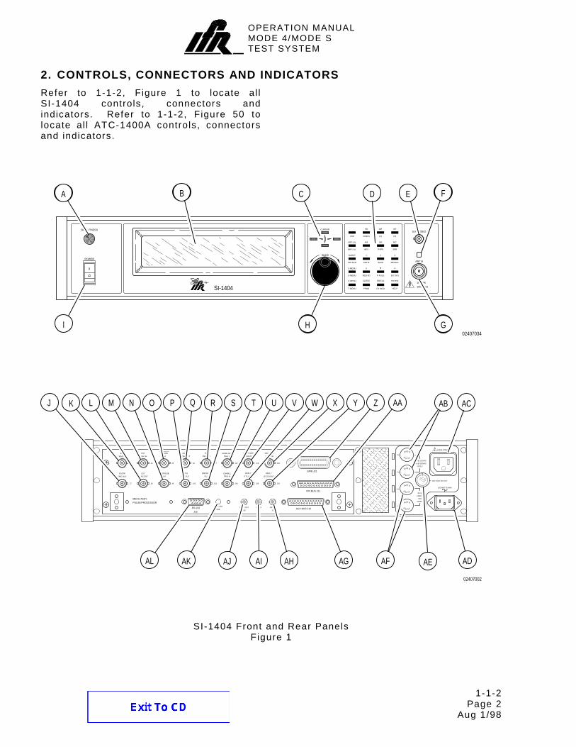
2. CONTROLS, CONNECTORS AND INDICATORS Refer to 1-1-2, Figure 1 to locate al l SI-1404 controls, connectors and indicators. Refer to 1-1-2, Figure 50 to locate al l ATC-1400A controls, connectors and indicators.
1kW PK
10W AVG
ANT B
UUT VIDEO
I
PPMG EX MOD
ON/CALCL/ESCC MENU
SEQ AD P PULS EX SYN
+/-0S MENU
ANT B SAVE RECALL
321BURST
7/D
2ND
8/E 9/F
P3P2FUNC#
ARF LVL 4/A 5/B 6/C
SPRP4/P6HEX
CURSOR
SLEW
POWER
BRIGHTNESS
BRF LVL
PRTSCR
U MENU
T MENU HELP
A B C D E F
GHI
ENTER
02407034
SI-1404
TYPE F
TYPE F
VOLTAGE SELECT
FE
F3
E S UF
3A @
110/230
FUS E
S U
VAC
F1
F4
115
USF E
.230
E S UF
FUS E
.
163 WATTS MAX
F2
E S UF
FUS E1400A POWER
1.0A @ 110VAC
0.5A @ 230VACJ3
SYNC IN
EXT
PULSE/PROCESSOR
MECH ASSY,
EXT
SYNC OUTTRIG OUT
SCOPE
J7
MOD IN
EXT
DPSK ADJRS-232
J12
PPMGR28
RF LVL
J13J14J15
DPSK OUT
J17
J23
VIDEO OUT
GEN OUT
PREPULSE
OUT
J8 J9
OUT
ATCRBS
J4 J5
J22
ANT B DISPARTY
OUT
J6
ANT B EXT
PRF OUT TRIG IN
REPLY GRP
REPLY
(TTL) OUT
ENABLE
TRIG IN
J24
MODE GRP
TRIG IN
J18
REPLY
(3-27V) OUT
J25 J26
VIDEO IN
DECODED
J19 J20
IFR BUS J11
AUX BUS J10
GPIB J21
24
1
AAZYXWVUTSRQPONMLKJ AB AC
ADAEAFAGAHAIAJAKAL
02407002
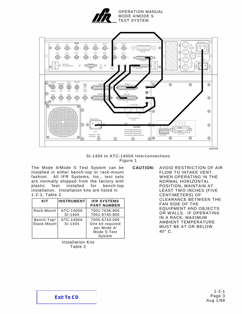
SI-1404 Front and Rear Panels Figure 1
OPERATION MANUALMODE 4/MODE STEST SYSTEM
1-1-2 Page 3
Aug 1/98
SI -1404 I tem Letter Locat ion List (Front Panel) :
A. BRIGHTNESS Contro l B. MENU Disp lay C. CURSOR Keys D. Keyboard E. UUT VIDEO Connector (J10001) F. UUT VIDEO Ind icator G. ANT B Connector (J10002) H. SLEW Contro l I . POW ER Switch
SI-1404 I tem Letter Locat ion List (Rear Panel) :
J . SCOPE TRIG OUT Connector (J7) K. EXT MOD IN Connector (J3) L. EXT SYNC OUT Connector (J8) M. EXT SYNC IN Connector (J4) N. PREPULSE OUT Connector (J9)
O. ATCRBS OUT Connector (J5) P. ANT B GEN OUT Connector (J22) Q. ANT B VIDEO OUT Connector (J6) R. EXT PRF OUT Connector (J17) S. DISPARITY OUT Connector (J23) T. MODE GRP TRIG IN Connector (J18) U. ENABLE TRIG IN Connector (J24) V. REPLY GRP TRIG IN Connector (J19) W . REPLY (TTL) OUT Connector (J25) X. DECODED VIDEO IN Connector (J20) Y. REPLY (3-27 V) OUT Connector (J26) Z. GPIB Connector (J21)
AA. IFR BUS Connector (J11) AB. F2 and F4 Fuses AC. 1400A POW ER Connector AD. AC IN Connector AE. VOLTAGE SELECT Swi tch AF. F1 and F3 Fuses AG. AUX BUS Connector (J10) AH. RF LVL Connector (J13) AI . PPMG Connector (J14) AJ. DPSK OUT Connector (J15) AK. DPSK ADJ (R28) AL. RS-232 Connector (J12)
Controls br ightness of the SI-1404 MENU Display back l ight. Rotat ing cw increases br ightness. Rotat ing ccw decreases br ightness.
B. MENU Display
Displays menus as selected on the SI-1404 Keyboard. Refer to 2.4 of 1-1-2 for menu descr ipt ions.
C. CURSOR Keys (↑, →, ↓, ← )
Select data or control f ields for edit ing. Cursor is shown as an underl ine below the selected f ield. Af ter posit ioning the cursor under the desired f ield, the Keyboard or SLEW Control edits the f ield.
D. Keyboard
Controls the microprocessor and is used for data entry. A Keyboard entry changes the character at the cursor posit ion and advances the cursor to the next character in that f ield. Refer to 2.3 of 1-1-2 for Keyboard key def ini t ions.
E. UUT VIDEO Connector (J10001)
Provides detected UUT transmission video received through the SI-1404 ANT B Connector.
ITEM DESCRIPTION F. UUT VIDEO Indicator
Green LED i l luminates when receiving transmitter repl ies through the SI-1404 ANT B Connector.
G. ANT B Connector (J10002)
CAUTION: MAXIMUM INPUT POW ER MUST NOT EXCEED 1 kW PEAK OR 10 W AVERAGE.
Provides access to a second RF channel for diversity test ing. The SI-1404 transmits interrogation s ignals through the ANT B Connector at a level selected in the C20 Function B Screens.
H. SLEW Control
Selects data by rotat ing in either a cw or ccw direct ion. Entire command and decimal data f ields are edited with one SLEW Control entry. Octal data f ields are changed one character at a t ime. SLEW Control input allows rapid advance to desired funct ion or data.
I . POW ER Switch or
Connects ( I) or disconnects (O ) external ac power to SI-1404 and 1400A POW ER Connector.
1kW PK
10W AVG
ANT B
UUT VIDEO
I
PPMG EX MOD
ON/CALCL/ESCC MENU
SEQ AD P PULS EX SYN
+/-0S MENU
ANT B SAVE RECALL
321BURST
7/D
2ND
8/E 9/F
P3P2FUNC#
ARF LVL 4/A 5/B 6/C
SPRP4/P6HEX
CURSOR
SLEW
POWER
BRIGHTNESS
BRF LVL
PRTSCR
U MENU
T MENU HELP
A B C D E F
GHI
ENTER
02407034
SI-1404
OPERATION MANUALMODE 4/MODE STEST SYSTEM
1-1-2 Page 5
Aug 1/98
2.2 SI-1404 REAR PANEL
ITEM DESCRIPTION J. SCOPE TRIG OUT Connector (J7)
Provides a scope tr igger for the interrogation or reply. The ATC-1400A TO/TAC/TD Switch and SI-1404 C72 Setup Screen control the s ignal output. Refer to Appendix A for tr igger pulse posit ion.
K. EXT MOD IN Connector (J3)
Provides the input for an external modulat ion source appl ied to the ANT A and/or ANT B output s ignals, control led in the SI-1404 C75 Setup Screen.
L. EXT SYNC OUT Connector (J8)
Provides a sync pulse control led in the SI-1404 C73 Setup Screen.
M. EXT SYNC IN Connector (J4)
Provides the input for an external sync source control led in the SI-1404 C71 Setup Screen.
N. PREPULSE OUT Connector (J9)
Provides a 1.0 µs long TTL Prepulse control led in the SI-1404 C75 Setup Screen.
ITEM DESCRIPTION
O. ATCRBS OUT Connector (J5)
Provides an act ive low 3.0 µs long ATCRBS Discrete pulse. The leading edge of the pulse occurs 1.0 µs pr ior to the leading edge of P1 in an Antenna A (ATC-1400A RF I/O Connector) ATCRBS interrogation.
P. ANT B GEN OUT Connector (J22)
Provides a digital version of the Antenna B output s ignal.
Q. ANT B VIDEO OUT Connector (J6)
Provides a digital version of the Antenna B reply s ignal viewed at the SI-1404 UUT VIDEO Connector.
R. EXT PRF OUT Connector (J17)
Provides a sync pulse when the SI-1404 is tr iggered. The tr igger source selected in the C71 Setup Screen also provides the source for the EXT PRF OUT sync pulse.
S. DISPARITY OUT Connector (J23)
Provides Dispar i ty, Interrogator Side Lobe Suppression ( ISLS) or Gain T ime Control (GTC) tr igger pulse in l ieu of an encryption device for the Mode 4 UUT Dispar i ty Input.
SYNC IN
EXT
EXT
SYNC OUTTRIG OUT
SCOPE
J7
MOD IN
EXT
J3 J17
J23
VIDEO OUT
GEN OUT
PREPULSE
OUT
J8 J9
OUT
ATCRBS
J4 J5
J22
ANT B DISPARTY
OUT
J6
ANT B EXT
PRF OUT
02407003
R SQPONMLKJ
OPERATION MANUALMODE 4/MODE STEST SYSTEM
1-1-2 Page 6
Aug 1/98
ITEM DESCRIPTION T. MODE GRP TRIG IN Connector (J18)
Reserved for future use.
U. ENABLE TRIG IN Connector (J24)
Receives the Enable Tr igger f rom a Mode 4 UUT when the Mode 4/Mode S Test System operates without external encryption devices (XPDR Mode 4 [ internal] funct ion).
V. REPLY GRP TRIG IN Connector (J19)
Reserved for future use.
W . REPLY (TTL) OUT Connector (J25)
Provides external pulse modulat ion (digi tal) to the UUT, s imulat ing an encryption device in Mode 4 or for ATCRBS transponders requir ing external encoding.
X. DECODED VIDEO IN Connector (J20)
Receives the T ime Decoded Video (TDV) input f rom an external encryption device for determining Mode 4 reply j i t ter .
Y. REPLY (3-27 V) OUT Connector (J26)
Provides external pulse modulat ion (analog) to the UUT, s imulat ing an encryption device in Mode 4 or for ATCRBS transponders requir ing external encoding.
ITEM DESCRIPTION Z. GPIB Connector (J21)
Provides a paral lel interface for general purpose programmable instrumentat ion. Electr ical character ist ics conform to IEEE-488.2 specif icat ions. Refer to Appendix A for pin-out table.
AA. IFR BUS Connector (J11)
Provides communication and control data between the ATC-1400A and the SI-1404 through the ATC-1400A IFR BUS Connector. Refer to Appendix A for pin-out table.
TRIG IN
REPLY GRP
REPLY
(TTL) OUT
ENABLE
TRIG IN
J24
MODE GRP
TRIG IN
J18
REPLY
(3-27V) OUT
J25 J26
VIDEO IN
DECODED
J19 J20
IFR BUS J11
GPIB J21
24
1
02407004
AAZYXWVUT
OPERATION MANUALMODE 4/MODE STEST SYSTEM
1-1-2 Page 7
Feb 1/99
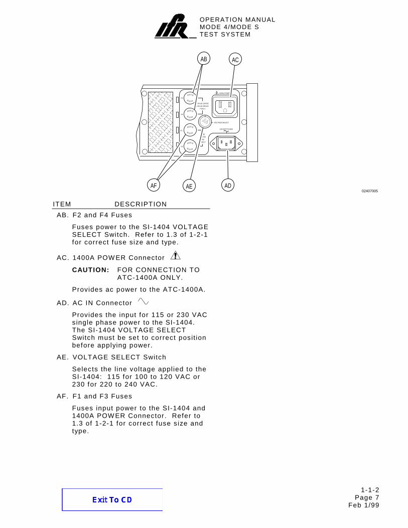
ITEM DESCRIPTION AB. F2 and F4 Fuses
Fuses power to the SI-1404 VOLTAGE SELECT Switch. Refer to 1.3 of 1-2-1 for correct fuse size and type.
AC. 1400A POW ER Connector
CAUTION: FOR CONNECTION TO ATC-1400A ONLY.
Provides ac power to the ATC-1400A.
AD. AC IN Connector
Provides the input for 115 or 230 VAC single phase power to the SI-1404. The SI-1404 VOLTAGE SELECT Switch must be set to correct posit ion before applying power.
AE. VOLTAGE SELECT Switch
Selects the l ine voltage appl ied to the SI-1404: 115 for 100 to 120 VAC or 230 for 220 to 240 VAC.
AF. F1 and F3 Fuses
Fuses input power to the SI-1404 and 1400A POW ER Connector. Refer to 1.3 of 1-2-1 for correct fuse size and type.
TYPE F
TYPE F
VOLTAGE SELECT
FE
F3
E S UF
3A @
110/230
FUS E
S U
VAC
F1
F4
115
USF E
.230
E S UF
FUS E
.
163 WATTS MAX
F2
E S UF
FUS E1400A POWER
1.0A @ 110VAC
0.5A @ 230VAC
02407005
AB AC
ADAEAF
OPERATION MANUALMODE 4/MODE STEST SYSTEM
1-1-2 Page 8
Aug 1/98
ITEM DESCRIPTION AG. AUX BUS Connector (J10)
Provides t iming and pulse s ignals between the ATC-1400A and the SI-1404 through the ATC-1400A AUXILIARY Connector. Refer to Appendix A for pin-out table.
AH. RF LVL Connector (J13)
Provides an analog output s ignal for vernier control over the ATC-1400A RF output level.
AI. PPMG Connector (J14)
Provides a Pulse Power Measurement Gate (PPMG) pulse to the ATC-1400A, control led in the SI-1404 C74 Setup Screen. The PPMG pulse selects a specif ic ATCRBS or Mode S Reply pulse for UUT power and f requency measurements. The ATC-1400A displays power measurements on the XMTR PW R W ATTS Display and f requency measurements on the XMTR FREQ MHz Display.
AJ. DPSK OUT Connector (J15)
Provides the DPSK modulat ion used in Mode S interrogations. The bipolar level s ignal dr ives the phase modulator in the ATC-1400A.
AK. DPSK ADJ (R28)
Sets a consistent ampli tude level for the Mode S interrogation phase reversals.
ITEM DESCRIPTION AL. RS-232 Connector (J12)
Provides a ser ial interface for remote control of the Mode 4/Mode S Test System. The SI-1404 GPIB and RS-232 Connectors support s imultaneous operat ion along with or without ATC-1400A GPIB. The SI-1404 C81 and C82 Setup Screens provide control over remote sett ings. Refer to Appendix A for pin-out table.
AL
J12
RS-232
AIAK AJ AH AG
DPSK OUT
J13
RF LVLDPSK ADJ
R28 J14
PPMG
J15AUX BUS J10
02407006
OPERATION MANUALMODE 4/MODE STEST SYSTEM
1-1-2 Page 9
Aug 1/98
2.3 KEYBOARD DEFINITION
2ND
7/D
FUNC#
8/E
P2
9/F
P3
ARF LVL
BRF LVL
4/A
HEX
5/B
P4/P6
6/C
SPR
BURST
PRTSCR
1
ANT B
2
SAVE
3
RECALL
S MENU
U MENU
0
SEQ AD
••••
P PULS
+/-
EX SYN
C MENU
T MENU
CL/ESC
PPMG
ON/CAL
EX MOD
ENTER
HELP
SI-1404 Keyboard Figure 2
The SI-1404 Keyboard consists of 20 keys (24 keys mechanical ly including the CURSOR Keys). The keys al low data entry for select ing funct ions, menu formats and f ield data. Al l keys have at least two functions and some have three. Pressing a s ingle key act ivates the selected f irst order funct ion (shown above each key in black). The 2ND Key al lows act ivat ion of second or third order funct ions. CURSOR Keys are located next to the Keyboard to expedite enter ing data.
2ND Key
The 2ND Key selects second order funct ions (shown below each key in blue) or third order funct ions (hexadecimal numbers >9) with the HEX Key. Pressing the 2ND Key and desired second order funct ion key act ivates the selected second order funct ion. The cursor box changes to an underl ine to indicate the 2ND Key has been pressed.
7 or FUNC# or D Key
The 7 Key enters the number 7 in control or data f ields.
Pressing the 2ND, FUNC# and both number Keys for selected function in sequence displays the corresponding funct ion screen according to the last used Control Menu C10 ( for Antenna A) or C20 (for Antenna B) function. Refer to 1-1-2, Table 1 for Function Select ions.
FUNCTION NUMBER
C10/C20 FUNCTION
SCREEN
INTERROGATION
FUNCTION 01 f01:ATC ATCRBS Only 02 f02:SEQ Mode S Only 03 f03:ACS ATCRBS Only Al l
Cal l 04 f04:ACL ATCRBS/Mode S
Al l Cal l 05 f05:INTLCE Inter lace (Mixed) 06 f06:DI Double
Pressing the 2ND, HEX and D Keys in sequence enters the number D (13) in hexadecimal data f ields.
OPERATION MANUALMODE 4/MODE STEST SYSTEM
1-1-2 Page 10
Aug 1/98
8 or P2 or E Key
The 8 Key enters the number 8 in control or data f ields.
Pressing the 2ND and P2 Keys in sequence moves the cursor to the P2 f ield for edit , i f val id for the current funct ion. The P2 Key funct ion operates f rom any menu and causes the SI-1404 to display the last entered appl icable C10 funct ion screen.
Pressing the 2ND, HEX and E Keys in sequence enters the number E (14) in hexadecimal data f ields.
9 or P3 or F Key
The 9 Key enters the number 9 in control or data f ields.
Pressing the 2ND and P3 Keys in sequence moves the cursor to the P3 f ield for edit , i f val id for the current funct ion. The P3 Key funct ion operates f rom any menu and causes the SI-1404 to display the last entered appl icable C10 funct ion screen.
Pressing the 2ND, HEX and F Keys in sequence enters the number F (15) in hexadecimal data f ields.
ARF LVL or BRF LVL Key
Pressing the ARF LVL Key moves the cursor to the Arf f ield for edit . The ARF LVL (RF Signal Level for Antenna A) Key funct ion operates f rom any menu and causes the SI-1404 to display the last entered C10 funct ion screen.
Pressing the 2ND and BRF LVL Keys in sequence moves the cursor to the Brf f ield for edit . The BRF LVL (RF Signal Level for Antenna B) Key function operates f rom any menu and causes the SI-1404 to display the C20 funct ion screen.
4 or HEX or A Key
The 4 Key enters the number 4 in control or data f ields.
Pressing the 2ND and HEX Keys in sequence al lows select ion of a s ingle digit number greater than nine (A, B, C, D, E and F) for hexadecimal data f ields. The Keyboard indicates hexadecimal numbers greater than nine in red above the corresponding keys.
Pressing the 2ND, HEX and A Keys in sequence enters the number A (10) in hexadecimal data f ields.
5 or P4/P6 or B Key
The 5 Key enters the number 5 in control or data f ields.
Pressing the 2ND and P4/P6 Keys in sequence moves the cursor to the P4 or P6 f ield for edit , i f val id for the current funct ion. The P4/P6 Key funct ion operates f rom any menu and causes the SI-1404 to display the last entered appl icable C10 funct ion screen.
Pressing the 2ND, HEX and B Keys in sequence enters the number B (11) in hexadecimal data f ields.
6 or SPR or C Key
The 6 Key enters the number 6 in control or data f ields.
Pressing the 2ND and SPR Keys in sequence moves the cursor to the SPR f ield for edit , i f val id for the current funct ion. The SPR (Synchronous Phase Reversal) Key funct ion operates f rom any menu and causes the SI-1404 to display the last entered appl icable C10 funct ion screen.
Pressing the 2ND, HEX and C Keys in sequence enters the number C (12) in hexadecimal data f ields.
OPERATION MANUALMODE 4/MODE STEST SYSTEM
1-1-2 Page 11
Feb 1/98
BURST or PRTSCR Key
The BURST Key act ivates the BURST Function when operat ing in the Burst Screen. W hen act ivated, the BURST Function transmits the number of interrogations specif ied in the C10/C20 f07 funct ion screen. I f enabled in the C71 Setup Screen as the tr igger source, the BURST Key ini t iates s ingle interrogations in other funct ions.
Pressing the 2ND and PRTSCR Keys in sequence performs a current screen dump out the RS-232 Connector (J12) i f enabled in the C81 RS232 Control System Screen.
1 or ANT B Key
The 1 Key enters the number 1 in control or data f ields.
Pressing the 2ND and ANT B Keys in sequence moves the cursor to the AntB f ield for edit . The ANT B (Antenna B) Key funct ion operates f rom any menu and causes the SI-1404 to display the last entered applicable C10 funct ion screen.
2 or SAVE Key
The 2 Key enters the number 2 in control or data f ields.
Pressing the 2ND and SAVE Keys in sequence displays the Save Conf igurat ion Screen for saving screen conf igurat ions in up to f ive non-volat i le memory Slots. Refer to 2.12.1 in 1-2-2 for Save operat ion.
3 or RECALL Key
The 3 Key enters the number 3 in control or data f ields.
Pressing the 2ND and RECALL Keys in sequence displays the Recal l Conf igurat ion Screen for recal l ing saved screen and factory default conf igurat ions. Refer to 2.12.2 in 1-2-2 for Recal l operat ion.
S MENU or U MENU Key
Pressing the S MENU and Sequence Menu number (000 to 999) Keys in sequence displays the corresponding sequence menu. Pressing the S MENU Key without a sequence number displays the last accessed sequence menu or the default S001 Sequence Menu on power-up.
The U MENU Key is reserved for future use.
MS SAVE CONFIGURATION
Slot 5: -- Empty -- Press ENTERto save.
MR RECALL CONFIGURATION
Slot 2: Yearly Cal Test Press ENTER27jul99,10:05:15 to recall.
Example Save and Recal l Conf igurat ion Screens Figure 3
OPERATION MANUALMODE 4/MODE STEST SYSTEM
1-1-2 Page 12
Aug 1/98
0 or SEQ AD Key
The 0 Key enters the number 0 in control or control or data f ields.
Pressing the 2ND and SEQ AD Keys in sequence moves cursor to the ADDR f ield (upl ink format address) for edit in the sequence menu. The SEQ AD (Sequential Address) Key funct ion operates f rom any menu and causes the SI-1404 to display the last displayed sequence menu or S001 Sequence Menu (default) .
• or P PULS Key
The • Key enters the decimal point in data f ields.
Pressing the 2ND and P PULS Keys in sequence moves the cursor to the C75 Setup Screen PrePulseOut f ield for edit. The P PULS (Prepulse) Key function operates f rom any menu and causes the SI-1404 to display the C75 Setup Screen.
+/- or EX SYN Key
The +/- Key changes a decimal data f ield value f rom posit ive (+ ) to negative (-) or vice versa without having to press the ENTER Key. The +/- Key funct ion, used af ter edit ing the decimal data f ield, displays the plus (+) or minus (-) s ign before the data. The +/- Key also cycles through act ive sequence menus when pressed with the cursor in the sequence menu S### f ield.
Pressing the 2ND and EX SYN Keys in sequence enters the C73 Setup Screen and moves the cursor to the ATC Enable f ield. The EX SYN (External Sync output) Key funct ion operates f rom any menu.
C MENU or T MENU Key
Pressing the C MENU and Control Menu Number (0-9) Keys in sequence enters the corresponding Control Menu. The 0 Key enters the Main Control Menu. Pressing the C MENU Key without a number enters the last accessed Control Menu.
Pressing the 2ND and T MENU Keys in sequence enters the last accessed Test Screen. Pressing the 2nd, T MENU and Test Menu Number (0-6) Keys in sequence enters the corresponding Test Screen. The 0 Key enters the Main Test Menu.
CL/ESC or PPMG Key
Pressing the CL/ESC Key dur ing an edit (before pressing the ENTER Key) c lears input data and restores previous data. The CL/ESC Key funct ion resets entire octal and hexadecimal data f ields to zero. Pressing the CL/ESC Key dur ing UUT measurements c lears reply information and resets to current reply input.
Pressing the 2ND and PPMG Keys in sequence enters the C74 Setup Screen. The PPMG (Pulse Power Measurement Gate) Key funct ion operates f rom any screen and al lows adjustment to measure the power of selected transponder pulses.
ON/CAL or EX MOD Key
The ON/CAL Key steps through the dif ferent states or values of control f ields having more than one state or value, changes interrogation addresses in address data f ields and starts or stops appl icable Test Menu operat ions.
Pressing the 2ND and EX MOD Keys in sequence enters the C75 Setup Screen. The EX MOD (External Modulat ion input) Key funct ion operates f rom any screen and al lows select ion of the modulat ion sources.
ENTER or HELP Key
The ENTER Key enters the current data or returns to the previous screen f rom Help screen. Pressing the ENTER Key af ter edit ing a data f ield saves the changes to any and al l f ields in the current screen.
The HELP Key is reserved for future use.
OPERATION MANUALMODE 4/MODE STEST SYSTEM
1-1-2 Page 13
Aug 1/98
2.4 DISPLAY MENU DEFINITION
The SI-1404 displays four menu types; Control, Sequence, Test and User. Control Menus include the funct ion screens, Setup Menus, System Menus and Calibrat ion Menus. Sequence menus (up to 1000 preset menus) load Mode S interrogation information and display reply content. Test Menus include the transponder capabi l i ty test, Extra Length Message (ELM) tests and other special information tests. The User Menu al lows up to nine user def inable screens ( loaded remotely) .
Al l screens have a screen reference designator in the upper lef t corner of the MENU Display. The screen reference designator indicates the screen type with a letter (C for Control Menu, S for Sequence Menu, T for Test Menu, MS for Memory Save or MR for Memory Recal l) . The numbers for a menu screen indicates a part icular subscreen.
Screens contain control and/or data f ields. Control f ields set test parameters and can be numeric (sett ing a value), select (select ing a mode or state), numeric/select (select ing a state and sett ing a value i f required by the selected state) or str ing (enter ing text) type. Data f ields contain numbers representing values or information. Fields not currently being updated or out of range display dashes. Fields immediately fol lowing a colon ( :) general ly specify values or sett ings selected by the operator. Fields immediately fol lowing an equal s ign (=) general ly specify values or information returned to the operator by the SI-1404. The sequence menus are an exception in that def ined data f ields, received or set, fol low an equal s ign.
NOTE: The SI-1404 provides the only val id percent reply information. Counting UUT Mode S squit ter (unsol ic i ted) transmissions makes the ATC-1400A DME-PRF Hz/XPDR-%REPLY Display inval id.
An error occurs when sett ing only one test set (SI-1404 or ATC-1400A) for Double Interrogations. The SI-1404 monitors the ATC-1400A DBL INTERR/INTRF PULSE Thumbwheels select ions. The DOUBLE posit ion is only val id with the SI-1404 DI Function act ive. The SI-1404 indicates this error by f lashing the message, * DI/ INTF ERROR * in the top l ine of the MENU Display in al l screens.
OPERATION MANUALMODE 4/MODE STEST SYSTEM
1-1-2 Page 14
Aug 1/98
2.4.1 Control Menus (CMENU)
C00 MAIN CMENU1)FUNC A 4)REPLY DELAY 7)SETUP MENU2)FUNC B 5)SQTR 1of2 8)SYSTEM MENU3)%REPLY 6)SQTR 2of2 9)CAL MENU
Main Control Menu Figure 4
Pressing C MENU and a number key (1-9) in sequence enters the appl icable Control Menu subscreen or last accessed screen of a part icular funct ion or subscreen group.
C10 FUNCTION A
Function A consists of screens for control and monitor of Antenna A (ATC-1400A RF I/O Connector) . Pulse sett ings also apply to the SI-1404 ANT B Connector output.
Function 01 displays the ATC Screen to operate the ATC Function. The ATC Screen al lows adjustment of the ATCRBS P3 pulse level in addit ion to monitor ing reply information and helping set the Antenna A RF level.
NOTE: The ATC-1400A provides most of the ATCRBS control.
FIELD DESCRIPTION C10 Editable menu f ield ( to enter other
Control Menu screens) indicates Control Menu 10.
FIELD DESCRIPTION f01 Editable funct ion f ield ( to enter
other Function A screens) indicates Function 01 ATC (ATCRBS).
Arf Editable RF Level vernier control combines with the ATC-1400A RF LEVEL Control to set the Antenna A output level through the ATC-1400A RF I/O Connector. The f ield ranges f rom -3.0 to +3.0 dB in 0.1 dB steps. The ATC-1400A RF LEVEL -dBm Display plus the Arf f ield sett ing indicates the true Antenna A output level.
OPERATION MANUALMODE 4/MODE STEST SYSTEM
1-1-2 Page 15
Aug 1/98
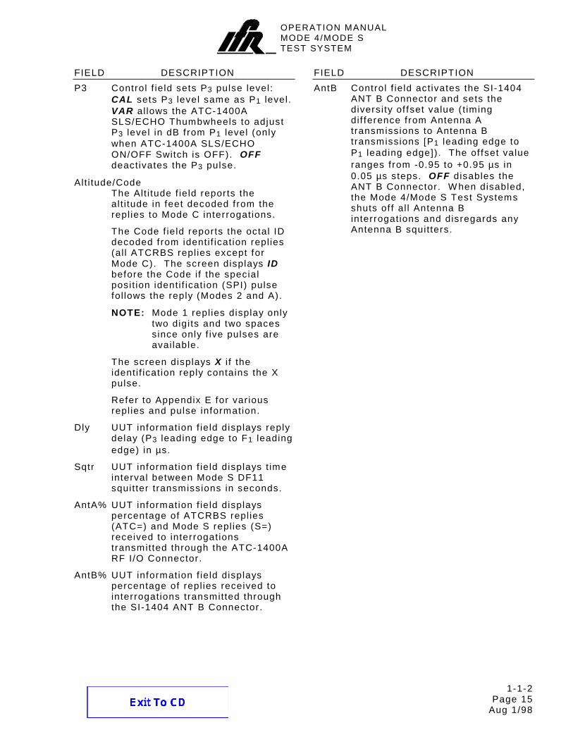
FIELD DESCRIPTION P3 Control f ield sets P3 pulse level:
CAL sets P3 level same as P1 level. VAR al lows the ATC-1400A SLS/ECHO Thumbwheels to adjust P3 level in dB f rom P1 level (only when ATC-1400A SLS/ECHO ON/OFF Switch is OFF). OFF deactivates the P3 pulse.
Alt i tude/Code The Alt i tude f ield reports the alt i tude in feet decoded f rom the repl ies to Mode C interrogations.
The Code f ield reports the octal ID decoded f rom identi f icat ion repl ies (al l ATCRBS repl ies except for Mode C). The screen displays ID before the Code i f the special posit ion identi f icat ion (SPI) pulse fol lows the reply (Modes 2 and A).
NOTE: Mode 1 repl ies display only two digi ts and two spaces since only f ive pulses are avai lable.
The screen displays X i f the identi f icat ion reply contains the X pulse.
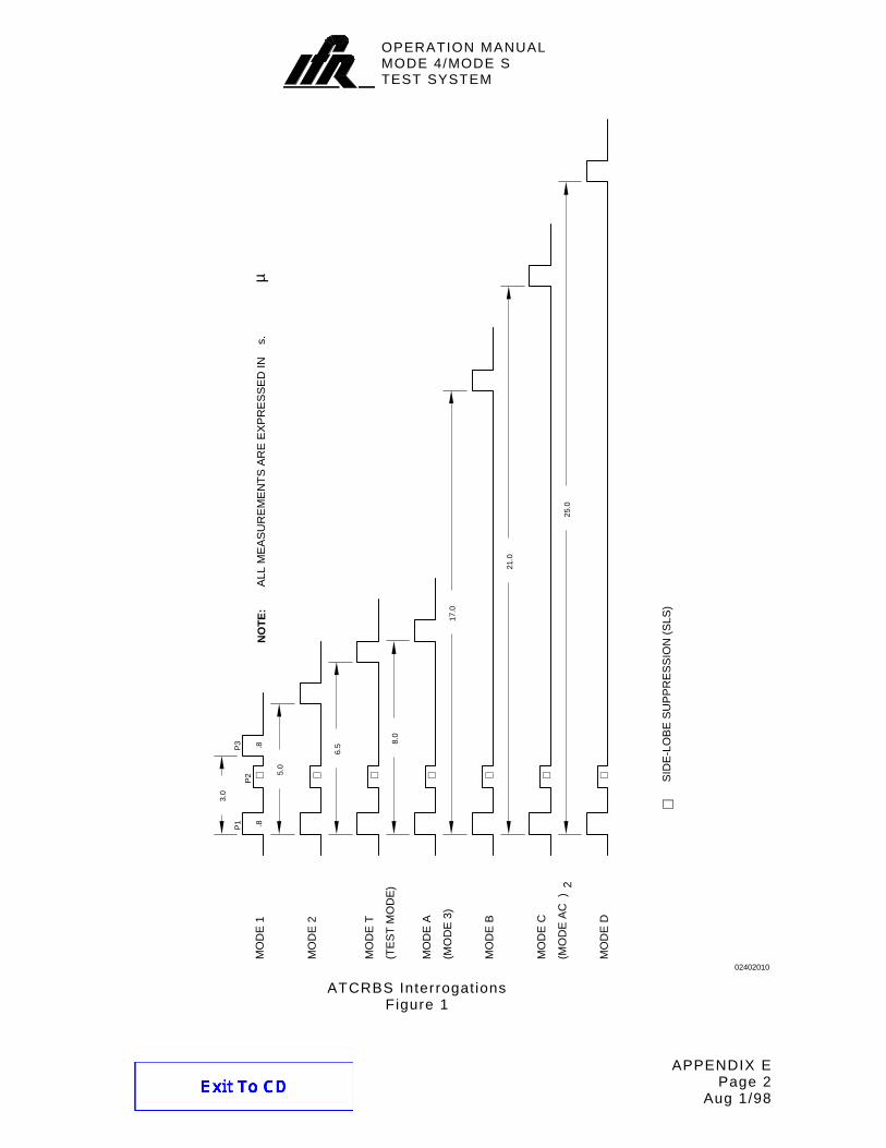
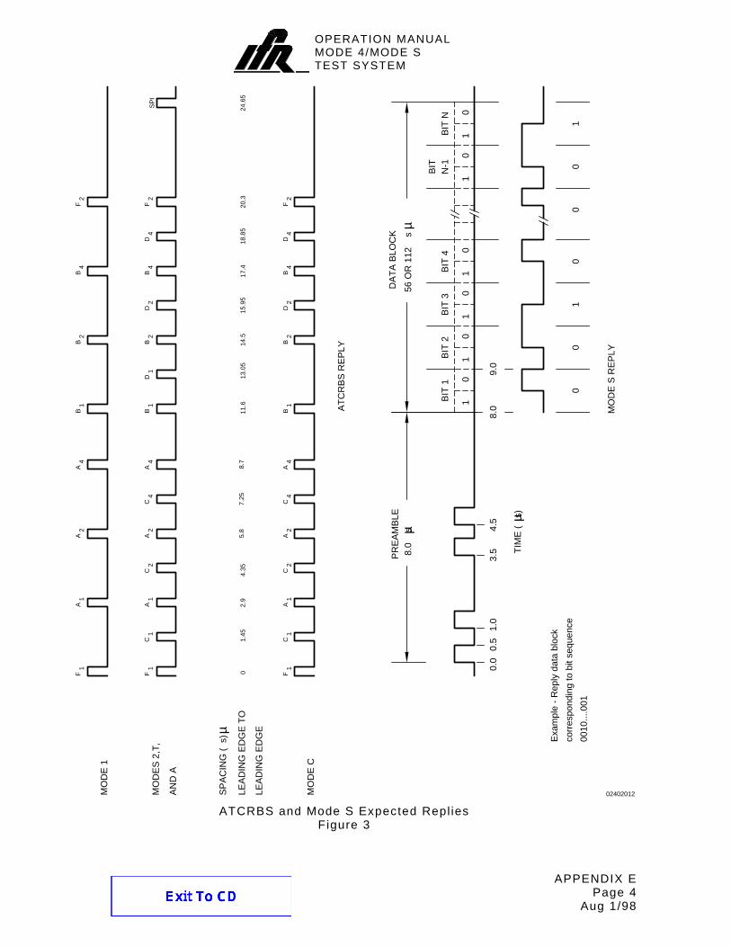
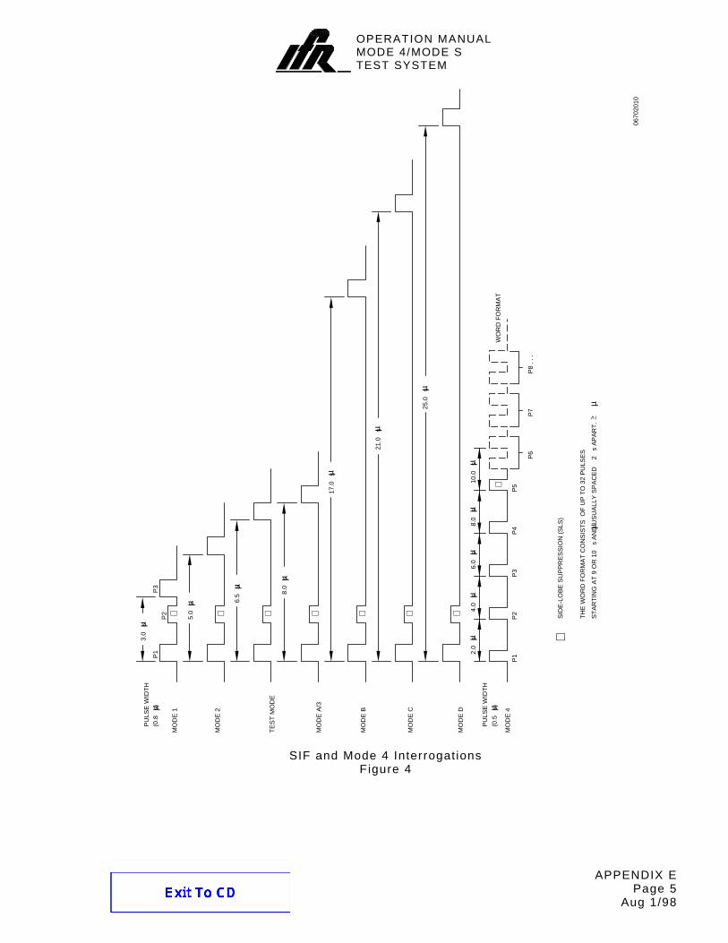
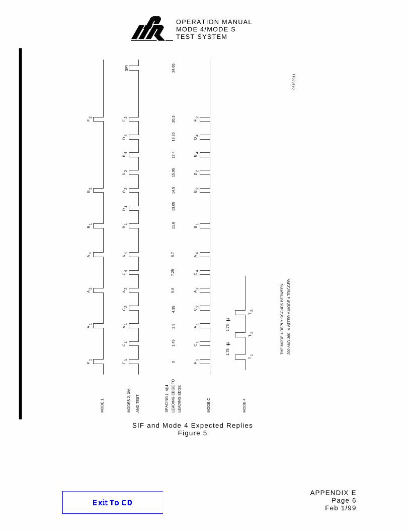
Refer to Appendix E for var ious repl ies and pulse information.
Dly UUT information f ield displays reply delay (P3 leading edge to F1 leading edge) in µs.
Sqtr UUT information f ield displays t ime interval between Mode S DF11 squit ter transmissions in seconds.
AntA% UUT information f ield displays percentage of ATCRBS repl ies (ATC=) and Mode S repl ies (S=) received to interrogations transmitted through the ATC-1400A RF I/O Connector.
AntB% UUT information f ield displays percentage of repl ies received to interrogations transmitted through the SI-1404 ANT B Connector.
FIELD DESCRIPTION AntB Control f ield act ivates the SI-1404
ANT B Connector and sets the diversity of fset value ( t iming dif ference f rom Antenna A transmissions to Antenna B transmissions [P1 leading edge to P1 leading edge]) . The of fset value ranges f rom -0.95 to +0.95 µs in 0.05 µs steps. OFF disables the ANT B Connector. W hen disabled, the Mode 4/Mode S Test Systems shuts of f al l Antenna B interrogations and disregards any Antenna B squit ters.
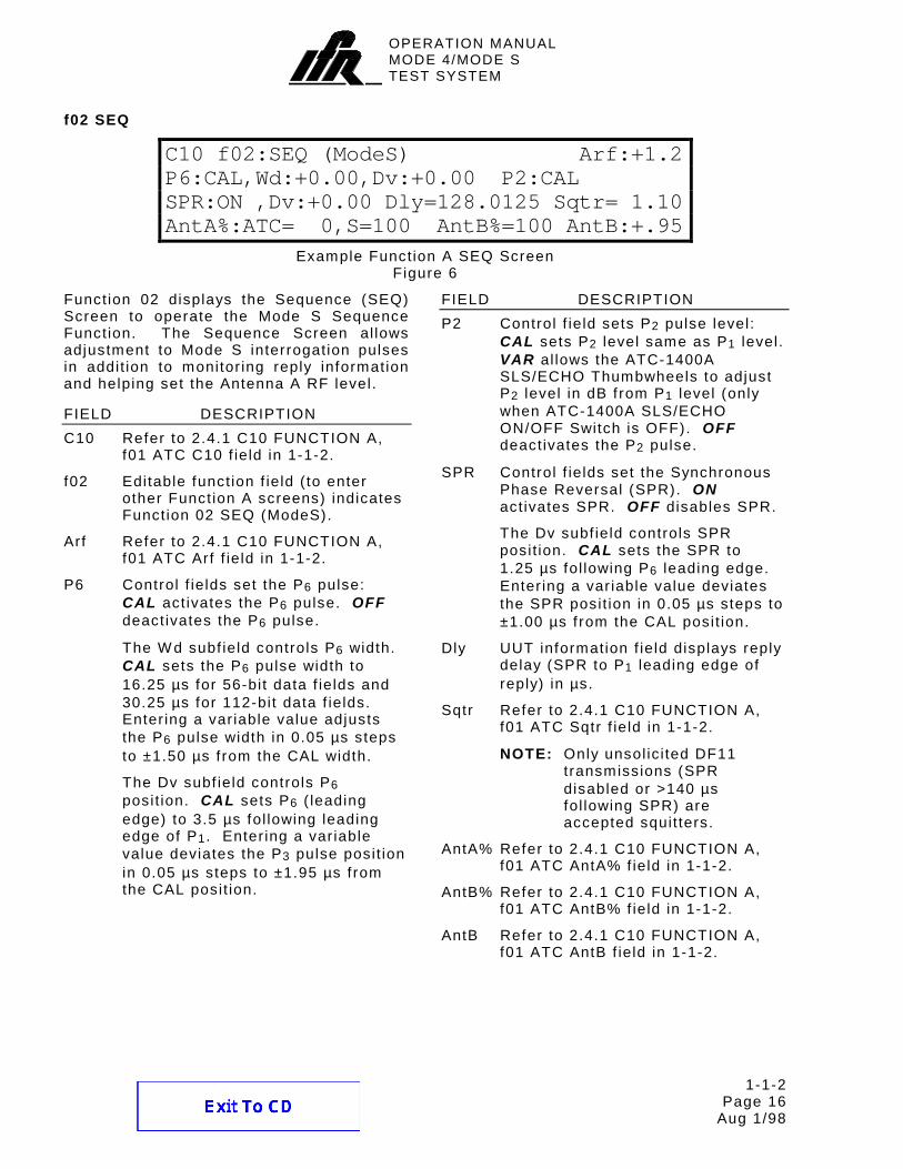
Function 02 displays the Sequence (SEQ) Screen to operate the Mode S Sequence Function. The Sequence Screen al lows adjustment to Mode S interrogation pulses in addit ion to monitor ing reply information and helping set the Antenna A RF level.
FIELD DESCRIPTION C10 Refer to 2.4.1 C10 FUNCTION A,
f01 ATC C10 f ield in 1-1-2.
f02 Editable funct ion f ield ( to enter other Function A screens) indicates Function 02 SEQ (ModeS).
Arf Refer to 2.4.1 C10 FUNCTION A, f01 ATC Arf f ield in 1-1-2.
P6 Control f ields set the P6 pulse: CAL act ivates the P6 pulse. OFF deactivates the P6 pulse.
The W d subf ield controls P6 width. CAL sets the P6 pulse width to 16.25 µs for 56-bit data f ields and 30.25 µs for 112-bit data f ields. Enter ing a var iable value adjusts the P6 pulse width in 0.05 µs steps to ±1.50 µs f rom the CAL width.
The Dv subf ield controls P6 posit ion. CAL sets P6 ( leading edge) to 3.5 µs fol lowing leading edge of P1. Enter ing a var iable value deviates the P3 pulse posit ion in 0.05 µs steps to ±1.95 µs f rom the CAL posit ion.
FIELD DESCRIPTION P2 Control f ield sets P2 pulse level:
CAL sets P2 level same as P1 level. VAR al lows the ATC-1400A SLS/ECHO Thumbwheels to adjust P2 level in dB f rom P1 level (only when ATC-1400A SLS/ECHO ON/OFF Switch is OFF). OFF deactivates the P2 pulse.
SPR Control f ields set the Synchronous Phase Reversal (SPR). ON act ivates SPR. OFF disables SPR.
The Dv subf ield controls SPR posit ion. CAL sets the SPR to 1.25 µs fol lowing P6 leading edge. Enter ing a var iable value deviates the SPR posit ion in 0.05 µs steps to ±1.00 µs f rom the CAL posit ion.
Dly UUT information f ield displays reply delay (SPR to P1 leading edge of reply) in µs.
Sqtr Refer to 2.4.1 C10 FUNCTION A, f01 ATC Sqtr f ield in 1-1-2.
NOTE: Only unsol ic i ted DF11 transmissions (SPR disabled or >140 µs fol lowing SPR) are accepted squit ters.
AntA% Refer to 2.4.1 C10 FUNCTION A, f01 ATC AntA% f ield in 1-1-2.
AntB% Refer to 2.4.1 C10 FUNCTION A, f01 ATC AntB% f ield in 1-1-2.
AntB Refer to 2.4.1 C10 FUNCTION A, f01 ATC AntB f ield in 1-1-2.
Function 03 displays the ACS (Al l Cal l Short) Screen for the ACS Funct ion and Funct ion 04 displays the ACL (Al l Cal l Long) Screen for the ACL Funct ion. Each screen sets the Mode 4/Mode S Test System for sending out appl icable Al l Cal l interrogations, monitors reply information and helps set the Antenna A RF level.
FIELD DESCRIPTION C10 Refer to 2.4.1 C10 FUNCTION A,
f01 ATC C10 f ield in 1-1-2.
f03 Editable funct ion f ield ( to enter other Funct ion A screens) indicates Funct ion 03 ACS (Al l Cal l Short) or 04 ACL (Al l Cal l Long).
Arf Refer to 2.4.1 C10 FUNCTION A, f01 ATC Arf f ield in 1-1-2.
P4 Control f ields set the P4 pulse: CAL sets P4 level same as P1 level. VAR al lows the ATC-1400A SLS/ECHO Thumbwheels to adjust P4 level in dB f rom P1 level (only when ATC-1400A SLS/ECHO ON/OFF Switch is OFF). OFF deact ivates the P4 pulse.
The W d: subf ield controls P4 width. CAL sets P4 width to 0.8 µs (ACS) or 1.6 µs (ACL). Enter ing a value f rom -0.6 to +2.75 (ACS) or -1.40 to +1.95 (ACL) adjusts P4 width in 0.05 µs steps f rom CAL width.
FIELD DESCRIPTION The Dv subf ield controls P4
posit ion. CAL sets P4 leading edge to 2.0 µs fol lowing P3 (act ive or disabled) leading edge locat ion. Enter ing a var iable value deviates P4 pulse posit ion in 0.05 µs steps to ±1.95 µs f rom the CAL posit ion.
P3 Refer to 2.4.1 C10 FUNCTION A, f01 ATC P3 f ield in 1-1-2.
DF Information f ield displays downl ink format f rom any Mode S reply.
AA Information f ield shows hexadecimal aircraf t address f rom DF11 repl ies.
Dly UUT information f ield displays reply delay (P3 to F1 or P4 to P1 [ leading edge to leading edge]) in µs.
Sqtr Refer to 2.4.1 C10 FUNCTION A, f01 ATC Sqtr f ield in 1-1-2.
NOTE: Accepted squitters are DF11 transmissions, unsol ic i ted, (P4 disabled or >141.8 µs fol lowing P4 trai l ing edge).
AntA% Refer to 2.4.1 C10 FUNCTION A, f01 ATC AntA% f ield in 1-1-2.
AntB% Refer to 2.4.1 C10 FUNCTION A, f01 ATC AntB% f ield in 1-1-2.
AntB Refer to 2.4.1 C10 FUNCTION A, f01 ATC AntB f ield in 1-1-2.
Funct ion 05 displays the Inter lace Screen for the Inter lace Funct ion. The Inter lace Screen sets the Mode 4/Mode S Test System for transmitt ing a mixture of Mode S and ATCRBS interrogations at a selected rat io.
FIELD DESCRIPTION C10 Refer to 2.4.1 C10 FUNCTION A,
f01 ATC C10 f ield in 1-1-2.
f05 Editable funct ion f ield ( to enter other Funct ion A screens) indicates Funct ion 05 INTLCE.
Ratio:1to Editable control number f ield sets the number (1 to 999) of ATCRBS interrogat ions transmitted for each Mode S interrogat ion transmitted.
Arf Refer to 2.4.1 C10 FUNCTION A, f01 ATC Arf f ield in 1-1-2.
Dly UUT information f ield displays reply delay (P3 to ATCRBS reply F1 or SPR to Mode S reply P1 [ leading edge to leading edge]) in µs.
Sqtr Refer to 2.4.1 C10 FUNCTION A, f01 ATC Sqtr f ield in 1-1-2.
AntA% Refer to 2.4.1 C10 FUNCTION A, f01 ATC AntA% f ield in 1-1-2.
AntB% Refer to 2.4.1 C10 FUNCTION A, f01 ATC AntB% f ield in 1-1-2.
AntB Refer to 2.4.1 C10 FUNCTION A, f01 ATC AntB f ield in 1-1-2.
Example Function A Double Interrogation Screen Figure 10
Function 06 displays the Double Interrogation (DI) Screen for the DI Function. The DI Screen sets the Mode 4/ Mode S Test System for sending out two selected types of interrogations (ATCRBS, Mode S, Al l Cal l Short or Al l Cal l Long) in the same t ime f rame as one normal interrogation.
FIELD DESCRIPTION C10 Refer to 2.4.1 C10 FUNCTION A,
f01 ATC C10 f ield in 1-1-2.
f06 Editable funct ion f ield ( to enter other Function A screens) indicates Function 06 DI.
The 1st f ield sets the f irst interrogation type (ATC, SEQ, ACS or ACL). Only the f irst interrogation type has editable control and data f ields.
The 2nd f ield sets the second interrogation type (ATC, SEQ, ACS or ACL).
NOTE: The SI-1404 displays f ields according to the 1st f ield sett ing. Refer to the part icular funct ion selected as the f irst interrogation for f ield def ini t ions.
Arf Refer to 2.4.1 C10 FUNCTION A, f01 ATC Arf f ield in 1-1-2.
Dly Refer to 2.4.1 C10 FUNCTION A, f05 INTLCE Dly f ield in 1-1-2.
Sqtr Refer to 2.4.1 C10 FUNCTION A, f01 ATC Sqtr f ield in 1-1-2.
AntA% Refer to 2.4.1 C10 FUNCTION A, f01 ATC AntA% f ield in 1-1-2.
AntB% Refer to 2.4.1 C10 FUNCTION A, f01 ATC AntB% f ield in 1-1-2.
FIELD DESCRIPTION AntB Refer to 2.4.1 C10 FUNCTION A,
Funct ion 07 displays the Burst Screen for the Burst Funct ion. The Burst Screen sets the Mode 4/Mode S Test System for sending out a selected type of interrogat ion (ATCRBS, Mode S, Al l Cal l Short or Al l Cal l Long) a selected amount of t imes.
FIELD DESCRIPTION C10 Refer to 2.4.1 C10 FUNCTION A,
f01 ATC C10 f ield in 1-1-2.
f07 Editable funct ion f ield ( to enter other Funct ion A screens) indicates Funct ion 07 BURST.
The ATC, SEQ, ACS or ACL f ield sets the type of interrogat ion. The number f ield (1 to 9999) sets the specif ic number of interrogations sent. For reference, the Burst Number (BN) refers to the number f ield value.
NOTE: The SI-1404 displays f ields according to the type of interrogat ion. For f ield def ini t ions, refer to the Funct ion A funct ion screen for the funct ion selected as the interrogat ion type.
Arf Refer to 2.4.1 C10 FUNCTION A, f01 ATC Arf f ield in 1-1-2.
Dly Refer to 2.4.1 C10 FUNCTION A, f05 INTLCE Dly f ield in 1-1-2.
Sqtr Refer to 2.4.1 C10 FUNCTION A, f01 ATC Sqtr f ield in 1-1-2.
AntA% Refer to 2.4.1 C10 FUNCTION A, f01 ATC AntA% f ield in 1-1-2.
AntB% Refer to 2.4.1 C10 FUNCTION A, f01 ATC AntB% f ield in 1-1-2.
AntB Refer to 2.4.1 C10 FUNCTION A, f01 ATC AntB f ield in 1-1-2.
Funct ion 08 displays the ATC Monitor Screen for the ATCRBS Monitor Pulse Funct ion. The ATC Monitor Screen sets the Mode 4/Mode S Test System for sending out selected ATCRBS interrogations and measur ing reply pulse parameters and j i t ter .
FIELD DESCRIPTION C10 Refer to 2.4.1 C10 FUNCTION A,
f01 ATC C10 f ield in 1-1-2.
f08 Editable funct ion f ield ( to enter other Funct ion A screens) indicates Funct ion 08 ATC Mon.
Mode Information f ield tracks interrogat ion mode set by the ATC-1400A XPDR MODE Control or ATCRBS f ield sett ing in the C79 Setup Screen when operat ing in the Stand Alone mode (1400 Control set to STAND-ALONE in the C84 System Screen). Possible modes are 1, 2, A, B, C, D or T.
Arf Refer to 2.4.1 C10 FUNCTION A, f01 ATC Arf f ield in 1-1-2.
F1toF2 UUT information f ield displays F1 to F2 reply pulse spacing in µs.
F1W d UUT information f ield displays F1 pulse width in µs.
F2W d UUT information f ield displays F2 pulse width in µs.
Dly Refer to 2.4.1 C10 FUNCTION A, f01 ATC Dly f ield in 1-1-2.
FIELD DESCRIPTION Alt i tude/Code
Refer to 2.4.1 C10 FUNCTION A, f01 ATC Alt i tude/Code f ield in 1-1-2.
Addit ional information may be added at the end of the f ield according to the reply as fol lows:
For emergency ident i f icat ion repl ies, the screen displays EM. For ident i f icat ion of posit ion ( I /P) repl ies, the screen displays IP .
J tr UUT information f ield displays reply j i t ter (di f ference between shortest and longest reply delays) in µs.
AntA% Refer to 2.4.1 C10 FUNCTION A, f01 ATC AntA% f ield in 1-1-2.
AntB% Refer to 2.4.1 C10 FUNCTION A, f01 ATC AntB% f ield in 1-1-2.
AntB Refer to 2.4.1 C10 FUNCTION A, f01 ATC AntB f ield in 1-1-2.
Function 10 displays the Mode 4 Screen for the Mode 4 ( Internal) and (External) Functions. The Mode 4 Screen sets the Mode 4/Mode S Test System for sending out selected Mode 4 interrogations, monitors reply information and helps set the Antenna A RF level.
FIELD DESCRIPTION C10 Refer to 2.4.1 C10 FUNCTION A,
f01 ATC C10 f ield in 1-1-2.
f10 Editable funct ion f ield ( to enter other Function A screens) indicates Function 10 Mode4.
Code Control f ield selects Mode 4 interrogation word format (A , B , ZERO [al l odd posit ions], ALL [al l pulse posit ions], NONE [al l P6-P37 pulses of f ] , RND [ random], EXT [external] or USER [user def ined with remote command]) . Refer to Appendix F.
NOTE: Changing the Code to EXT f rom any other select ion sets the PrePulseOut f ield to OFF , the AntAModSrc f ield to INT and the AntBModSrc f ield to INT in the C75 Setup Screen. Changing the Code to any other select ion f rom EXT sets the PrePulseOut f ield to ON , the AntAModSrc f ield to INT/EXT and the AntBModSrc f ield to INT/EXT in the C75 Setup Screen.
Arf Refer to 2.4.1 C10 FUNCTION A, f01 ATC Arf f ield in 1-1-2.
FIELD DESCRIPTION P2 Control f ield, set to CAL , enables
the nominal 0.5 µs P2 pulse in the Mode 4 interrogation preamble. The ATC-1400A XPDR DEV P2/CAL Switch and XPDR P2/P3 DEV Thumbwheels vary pulse posit ion f rom nominal (2 µs fol lowing P1) ±1.95 µs in 0.05 µs steps. OFF disables the P2 pulse.
P3 Control f ield, set to CAL , enables the nominal 0.5 µs P3 pulse in the Mode 4 interrogation preamble. The ATC-1400A XPDR DEV P3/CAL Switch and XPDR P2/P3 DEV Thumbwheels vary pulse posit ion f rom nominal (4 µs fol lowing P1) ±1.95 µs in 0.05 µs steps. OFF disables the P3 pulse.
P4 Control f ield, set to CAL , enables the nominal 0.5 µs P4 pulse in the Mode 4 interrogation preamble. OFF disables the P4 pulse.
Dv Control f ield sets P4 pulse posit ion. CAL sets P4 pulse posit ion to the nominal 6 µs fol lowing P1. Entering a var iable value deviates P4 pulse posit ion ±1.95 µs in 0.05 µs steps f rom the CAL posit ion.
TDV Jtr UUT information f ield displays P4 to the T ime Decoded Video (TDV) pulse j i t ter (di f ference between shortest and longest delays) in µs. The external encryption device sends the TDV pulse to the SI-1404 through the DECODED VIDEO IN Connector (J20).
OPERATION MANUALMODE 4/MODE STEST SYSTEM
1-1-2 Page 23
Aug 1/98
FIELD DESCRIPTION Dly UUT information f ield displays reply
delay (P4 leading edge to T1 leading edge) in µs.
Jtr Refer to 2.4.1 C10 FUNCTION A, f08 ATC Mon Jtr f ield in 1-1-2.
A% Refer to 2.4.1 C10 FUNCTION A, f01 ATC AntA% f ield in 1-1-2.
The addit ional M4= subf ield displays the percentage of Mode 4 repl ies.
B% Refer to 2.4.1 C10 FUNCTION A, f01 ATC AntB% f ield in 1-1-2.
AntB Refer to 2.4.1 C10 FUNCTION A, f01 ATC AntB f ield in 1-1-2.
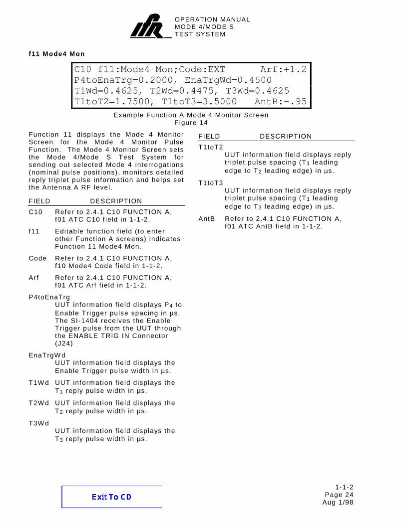
Example Function A Mode 4 Monitor Screen Figure 14
Function 11 displays the Mode 4 Monitor Screen for the Mode 4 Monitor Pulse Function. The Mode 4 Monitor Screen sets the Mode 4/Mode S Test System for sending out selected Mode 4 interrogations (nominal pulse posit ions), monitors detai led reply tr iplet pulse information and helps set the Antenna A RF level.
FIELD DESCRIPTION C10 Refer to 2.4.1 C10 FUNCTION A,
f01 ATC C10 f ield in 1-1-2.
f11 Editable funct ion f ield ( to enter other Function A screens) indicates Function 11 Mode4 Mon.
Code Refer to 2.4.1 C10 FUNCTION A, f10 Mode4 Code f ield in 1-1-2.
Arf Refer to 2.4.1 C10 FUNCTION A, f01 ATC Arf f ield in 1-1-2.
P4toEnaTrg UUT information f ield displays P4 to Enable Tr igger pulse spacing in µs. The SI-1404 receives the Enable Tr igger pulse f rom the UUT through the ENABLE TRIG IN Connector (J24)
EnaTrgW d UUT information f ield displays the Enable Tr igger pulse width in µs.
T1W d UUT information f ield displays the T1 reply pulse width in µs.
T2W d UUT information f ield displays the T2 reply pulse width in µs.
T3W d UUT information f ield displays the T3 reply pulse width in µs.
FIELD DESCRIPTION T1toT2
UUT information f ield displays reply tr iplet pulse spacing (T1 leading edge to T2 leading edge) in µs.
T1toT3 UUT information f ield displays reply tr iplet pulse spacing (T1 leading edge to T3 leading edge) in µs.
AntB Refer to 2.4.1 C10 FUNCTION A, f01 ATC AntB f ield in 1-1-2.
Function B consists of the same function screens as Function A except for the Brf , AntA% or A% and AntB% or B% f ields. Function B screens set interrogation funct ions to control and monitor Antenna B (SI-1404 ANT B Connector) . Pulse sett ings also apply to the ATC-1400A RF I/O Connector output.
FIELD DESCRIPTION C20 Editable menu f ield ( to enter other
Control Menu screens) indicates Control Menu 20.
f## Editable funct ion f ield ( to enter other Function B screens) indicates current funct ion.
NOTE: The SI-1404 displays f ields according to the funct ion type. Refer to the same Function A funct ion screen for f ield def ini t ions.
Brf Two f ields al low control of the Antenna B level.
The f irst f ield sets the Antenna B main output s ignal level (-83 to -20) in dBm.
The second f ield, the RF Level vernier control, combines with the f irst f ield to set the Antenna B output level through the SI-1404 ANT B Connector. The f ield ranges f rom -3.0 to +3.0 dB in 0.1 dB steps. Both f ields add together to indicate the true Antenna B output level.
FIELD DESCRIPTION AntB% or B%
UUT information f ield displays percentage of ATCRBS repl ies (ATC=), Mode S repl ies (S=) and Mode 4 repl ies (M4=) received to interrogations transmitted through the SI-1404 ANT B Connector.
AntA% or A% UUT information f ield displays percentage of repl ies received to interrogations transmitted through the ATC-1400A RF I/O Connector.
AntB Control f ield act ivates the SI-1404 ANT B Connector and sets the diversity of fset value ( t iming dif ference f rom Antenna A transmissions to Antenna B transmissions [P1 leading edge to P1 leading edge]) . The of fset value ranges f rom -0.95 to +0.95 µs in 0.05 µs steps. OFF disables the ANT B Connector. W hen disabled, the Mode 4/Mode S Test Systems shuts of f al l Antenna B interrogations and disregards any Antenna B squit ters.
OPERATION MANUALMODE 4/MODE STEST SYSTEM
1-1-2 Page 26
Aug 1/98
C30 PERCENT REPLY
C30 PERCENT REPLYATC ModeS Mode4 BAD NOREPLY
AntA%= 70 10 10 5 5AntB%= 60 10 20 5 5
Example Percent Reply Screen Figure 16
FIELD DESCRIPTION C30 Editable menu f ield ( to enter other
Control Menu screens) indicates Control Menu 30.
AntA% UUT information f ields display percentage of repl ies received to interrogations transmitted through the ATC-1400A RF I/O Connector.
AntB% UUT information f ields display percentage of repl ies received to interrogations transmitted through the SI-1404 ANT B Connector.
ATC UUT information f ields display percentage of ATCRBS repl ies received to interrogations transmitted.
ModeS UUT information f ields display percentage of Mode S repl ies received to interrogations transmitted.
Mode4 UUT information f ields display percentage of Mode 4 repl ies received to interrogations transmitted.
BAD UUT information f ields display percentage of bad (out of specif icat ion) repl ies received to interrogations transmitted.
NOREPLY UUT information f ields display percentage of interrogations transmitted having no repl ies received.
FIELD DESCRIPTION NOTE : Pressing the SI-1404 CL/ESC Key
with the Percent Reply Screen displayed or changing interrogation funct ion (e.g. ATC→SEQ or SEQ→ACS) ini t ial izes percent reply f ields to current percent reply readings.
FIELD DESCRIPTION C40 Editable menu f ield ( to enter other
Control Menu screens) indicates Control Menu 40.
ATC UUT information f ields display ATCRBS reply delays in µs (P3 leading edge to F1 leading edge). The f irst f ield indicates the current ATCRBS reply delay. The Min= f ield indicates the shortest ATCRBS reply delay dur ing the current test. The Max= f ield indicates the longest ATCRBS reply delay dur ing the current test.
ModeS UUT information f ields display Mode S reply delays in µs (SPR to P1 leading edge). The f irst f ield indicates the current Mode S reply delay. The Min= f ield indicates the shortest Mode S reply delay dur ing the current test. The Max= f ield indicates the longest Mode S reply delay dur ing the current test.
Mode4 UUT information f ields display Mode 4 reply delays in µs (P4 leading edge to T1 leading edge). The f irst f ield indicates the current Mode 4 reply delay. The Min= f ield indicates the shortest Mode 4 reply delay dur ing the current test. The Max= f ield indicates the longest Mode 4 reply delay dur ing the current test.
FIELD DESCRIPTION NOTE : Pressing the SI-1404 CL/ESC Key
with the Reply Delay Screen displayed or changing interrogation funct ion (e.g. ATC→SEQ or SEQ→ACS) ini t ial izes reply delay f ields to current reply delay readings.
FIELD DESCRIPTION C50 Editable menu f ield ( to enter other
Control Menu screens) indicates Control Menu 50.
Capt Indicates data in the squit ter capture buf fer. W ithout data in the squit ter capture buf fer, the Squit ter Screens do not display Capt . The squit ter capture buf fer can only be examined using remote commands.
Addr UUT information f ields display the Mode S Address f rom received squit ters in hexadecimal (h=) and octal (o=) formats.
The Tai l= f ield displays the Tai l Number decoded f rom the UUT Mode S Address.
The Country= f ield displays the name of the country, when decoded f rom the most s ignif icant bi ts of the UUT Mode S Address.
Counts Editable data f ield sets the t ime in seconds (10 to 300) to count received squit ters before start ing the count over.
The DF11= f ield indicates number of DF11 squit ters received dur ing the current or last t ime per iod.
FIELD DESCRIPTION The DF17= f ield indicates number
of DF17 squit ters received dur ing the current or last t ime per iod.
The DF17X= f ield indicates number of DF17 X type squit ters received dur ing the current or last t ime per iod. The editable X (A, I , O, P, S or T) selects the type of DF17 squit ters counted. Refer to 1-1-2, Table 2 for select ion descr ipt ion.
SELECTION DESCRIPTION A Airborne Posit ion I Aircraft Ident i f icat ion O Other P On-Demand Information
(Pi lot Report) S Surface Posit ion T Airborne
Supplementary Information (Trend)
DF17 Squit ter Select ion Table 2
NOTE : Pressing the SI-1404 CL/ESC Key with the Squit ter (1 of 2) Screen displayed or changing interrogation funct ion (e.g. ATC→SEQ or SEQ→ACS) ini t ial izes squit ter count f ields to zero.
OPERATION MANUALMODE 4/MODE STEST SYSTEM
1-1-2 Page 29
Aug 1/98
C60 SQUITTER (2 of 2)
C60 SQUITTER (2of2)DF CA AA ME II ANT TIME11 6 A55A6A *0 A 1.1017A 6 A55A6A 50A421555420A1 0 B 0.51
Example Squit ter (2 of 2) Screen Figure 19
FIELD DESCRIPTION C60 Editable menu f ield ( to enter other
Control Menu screens) indicates Control Menu 60.
Capt Refer to 2.4.1 C50 SQUITTER (1 of 2) Capt f ield in 1-1-2.
DF11 UUT information f ields display decoded DF11 squit ter data.
DF17X UUT information f ields display decoded DF17 squit ter data.
The editable X (A, I , O, P, S or T) selects the type of DF17 squit ter displayed. Refer to 1-1-2, Table 2 for select ion descr ipt ion.
CA UUT information f ields display transponder capabi l i ty data in hexadecimal f rom last squit ter .
AA UUT information f ields display aircraf t address data in hexadecimal f rom last squit ter .
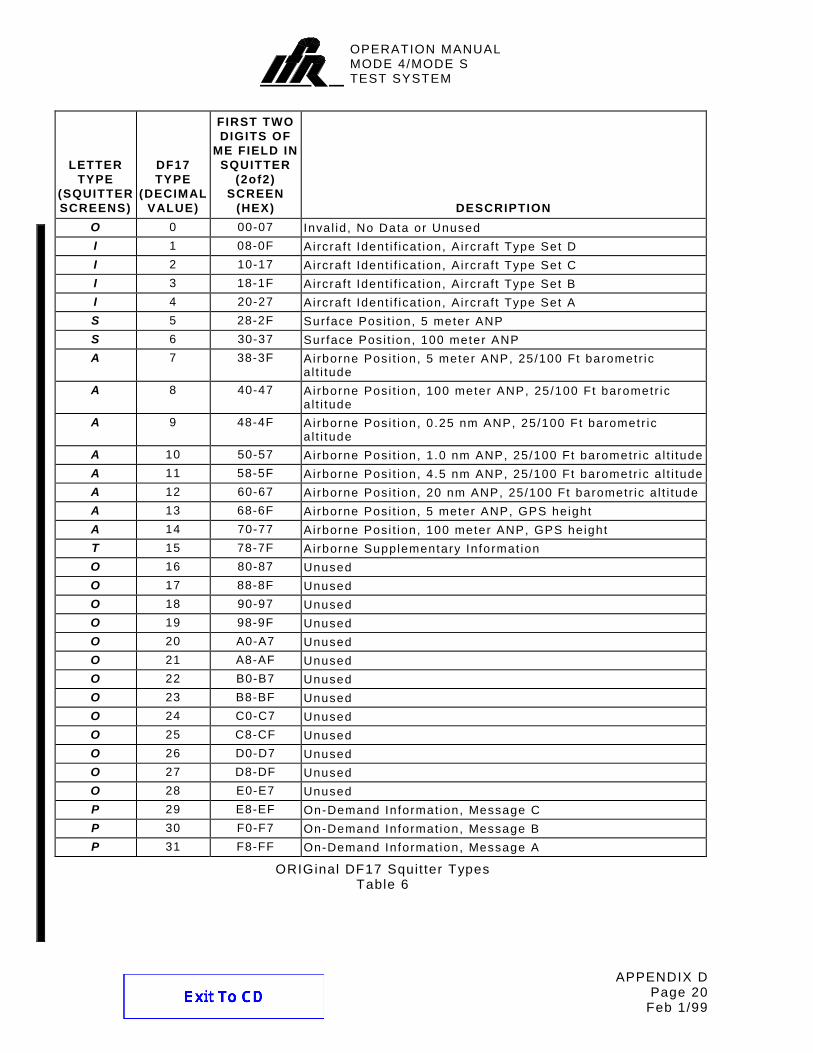
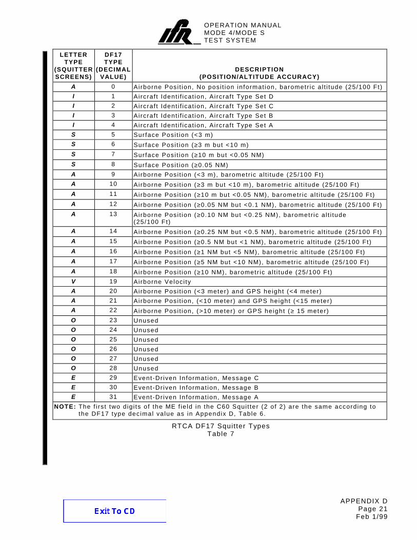
ME UUT information f ield displays extended squit ter message data in hexadecimal f rom last squit ter . The f irst f ive bits indicate the type of DF17 squit ter received according to Appendix D, Table 6.
I I UUT information f ields display the last (bottom) four bi ts of the converted PI address f ield in hexadecimal (normally zero for squit ters). I f the f irst ( top) 20 bits of the converted PI f ield (normally zero) have a non-zero value an * appears before the I I f ield.
ANT UUT information f ields report the last squit ter received was through what antenna (A or B).
FIELD DESCRIPTION TIME UUT information f ields display t ime
between the last two squit ters in seconds.
NOTE : Pressing the SI-1404 CL/ESC Key with the Squit ter (2 of 2) Screen displayed or changing interrogation funct ion (e.g. ATC→SEQ or SEQ→ACS) ini t ial izes squit ter data f ields to current readings.
Squitter Period Measurement Parameters Range: DF11: 0.01 to 3.00 seconds DF17A: 0.01 to 1.50 seconds DF17S: 0.01 to 15.00 seconds DF17I: 0.01 to 30.00 seconds DF17T: 0.01 to 1.50 seconds DF17P: 0.01 to 65.53 seconds DF17O: 0.01 to 65.53 seconds Resolut ion: 10 ms Accuracy: ±10 ms, ±0.005%
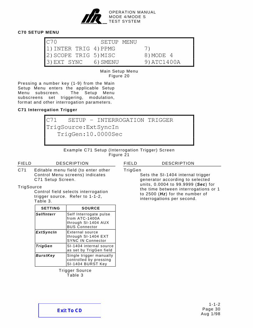
Pressing a number key (1-9) f rom the Main Setup Menu enters the appl icable Setup Menu subscreen. The Setup Menu subscreens set tr igger ing, modulat ion, format and other interrogation parameters.
Example C71 Setup ( Interrogation Tr igger) Screen Figure 21
FIELD DESCRIPTION C71 Editable menu f ield ( to enter other
Control Menu screens) indicates C71 Setup Screen.
Tr igSource Control f ield selects interrogation tr igger source. Refer to 1-1-2, Table 3.
SETTING SOURCE SelfInterr Self Interrogate pulse
from ATC-1400A through SI-1404 AUX BUS Connector
ExtSyncIn External source through SI-1404 EXT SYNC IN Connector
TrigGen SI-1404 internal source as set by TrigGen f ie ld
BurstKey Single tr igger manual ly control led by pressing SI-1404 BURST Key
Tr igger Source Table 3
FIELD DESCRIPTION Tr igGen
Sets the SI-1404 internal tr igger generator according to selected units, 0.0004 to 99.9999 (Sec) for the t ime between interrogations or 1 to 2500 (Hz ) for the number of interrogations per second.
OPERATION MANUALMODE 4/MODE STEST SYSTEM
1-1-2 Page 31
Aug 1/98
C72 Scope Trigger
C72 SETUP - SCOPE TRIGGERATC ModeS ACS ACL Mode4
Enable:OFF ON OFF OFF OFFSource:CAL 150 CAL CAL CAL (in µS)
Example C72 Setup (Scope Tr igger) Screen Figure 22
FIELD DESCRIPTION C72 Editable menu f ield ( to enter other
Control Menu screens) indicates C72 Setup Screen.
Enable Control f ield act ivates (ON) or deactivates (OFF) tr igger output at the SI-1404 SCOPE TRIG OUT Connector for each interrogation type.
Source Control f ield sets t iming for each interrogation type: CAL to reference the ATC-1400A TO/TAC/TD Switch or a var iable numeric value. Refer to Appendix A for the TO and TD pulse posit ions. The var iable numeric value sets the tr igger posit ion in µs referenced to the leading edge of the Antenna A interrogation P1 pulse. In al l modes, sett ing the scope tr igger t iming to the var iable numeric value f ixes the scope tr igger pulse width at 1 µs.
ATC Control f ields set tr igger output and t iming for ATCRBS interrogations.
ModeS Control f ields set tr igger output and t iming for Mode S interrogations.
ACS Control f ields set tr igger output and t iming for Al l Cal l Short interrogations.
ACL Control f ields set tr igger output and t iming for Al l Cal l Long interrogations.
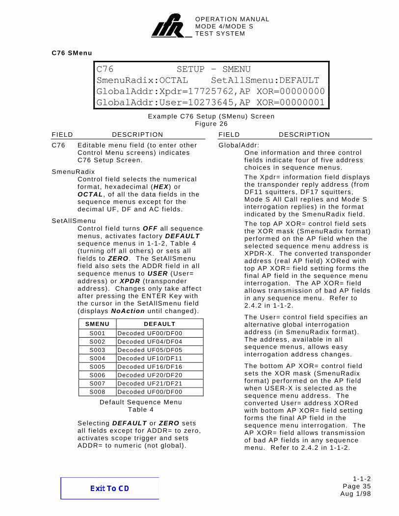
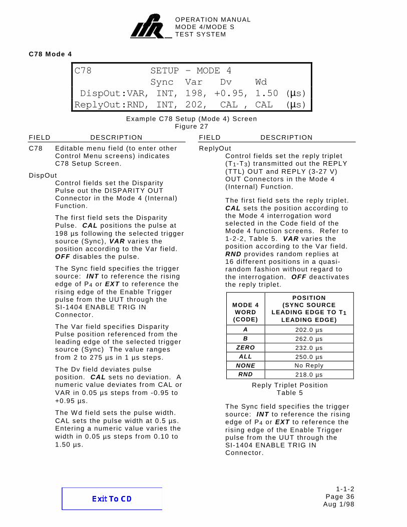
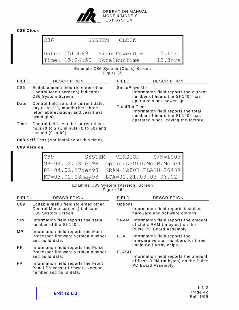
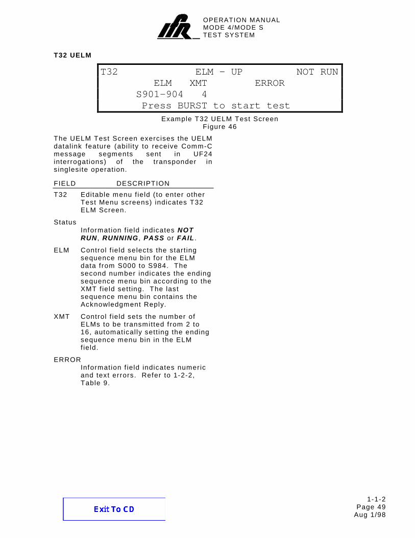
FIELD DESCRIPTION Mode4
Control f ields set tr igger output and t iming for Mode 4 interrogations.
OPERATION MANUALMODE 4/MODE STEST SYSTEM
1-1-2 Page 32
Aug 1/98
C73 Ext Sync Out
C73 SETUP - EXT SYNC OUTATC ModeS ACS ACL Mode4
Enable:OFF ON OFF OFF OFFDv:+0.00µS
Example C73 Setup (Ext Sync Out) Screen Figure 23
FIELD DESCRIPTION C73 Editable menu f ield ( to enter other
Control Menu screens) indicates C73 Setup Screen.
Enable Control f ield act ivates (ON) or deactivates (OFF) external sync pulse output at the SI-1404 EXT SYNC OUT Connector for each interrogation type.
ATC Control f ield act ivates or deactivates external sync pulse output for ATCRBS interrogations.
ModeS Control f ield act ivates or deactivates external sync pulse output for Mode S interrogations.
ACS Control f ield act ivates or deactivates external sync pulse output for Al l Cal l Short interrogations.
ACL Control f ield act ivates or deactivates external sync pulse output for Al l Cal l Long interrogations.
Mode4 Control f ield act ivates or deactivates external sync pulse output for Mode 4 interrogations.
Dv Control f ield sets the sync pulse posit ion f rom -9.95 to +9.95 µs, in reference to the start of the Antenna A interrogation P1 pulse.
OPERATION MANUALMODE 4/MODE STEST SYSTEM
1-1-2 Page 33
Aug 1/98
C74 PPMG
C74 SETUP - PPMG (POWER)ATC ModeS DELM Mode4
Enable:OFF OFF OFF OFFPulse:A1 P116 1 T1
Example C74 Setup (PPMG) Screen Figure 24
NOTE: For the SI-1404 to control pulse power measurement, the ATC-1400A F2/P2 F1/P1 Switch must be set to F2/P2 .
FIELD DESCRIPTION C74 Editable menu f ield ( to enter other
Control Menu screens) indicates C74 Setup Screen.
Enable Control f ields act ivate (ON) or deactivate (OFF) Pulse Power Measurement Gate (PPMG) operat ion for each reply type.
Pulse Control f ields select the reply pulse to measure for each reply type. The Mode 4/Mode S Test System measures power and f requency of the selected pulse.
ATC Control f ields set PPMG operat ion for ATCRBS repl ies.
The ATC Enable f ield act ivates (ON) or deactivates (OFF) PPMG operat ion.
The Mode 4/Mode S Test System performs power and f requency measurements on the ATCRBS reply pulse (F1 , C1 , A1 , C2 , A2 , C4 , A4 , X , B1 , D1 , B2 , D2 , B4 , D4 , F2 or SPI) selected in the ATC Pulse f ield.
ModeS Control f ields set PPMG operat ion for Mode S repl ies.
The ModeS Enable f ield act ivates (ON) or deactivates (OFF) PPMG operat ion.
FIELD DESCRIPTION The Mode 4/Mode S Test System
performs power and f requency measurements on the Mode S reply pulse (P001 to P116) selected in the ModeS Pulse f ield.
DELM Control f ields set PPMG operat ion for Downlink Extended Length Messages (DELM).
The DELM Enable f ield act ivates (ON) or deactivates (OFF) PPMG operat ion.
Act ivat ing the DELM Enable f ield automatical ly sets ATC Pulse f ield to F1 because the SI-1404 sends ATCRBS interrogations pr ior to the f irst Mode S to accurately set up the ATC-1400A PPMG operat ion.
NOTE: The SI-1404 DSP does not measure power on the CloseOut reply.
The Mode 4/Mode S Test System performs power and f requency measurements on the selected Mode S reply pulse (ModeS pulse f ield) in the message (1 to 16) selected in the DELM Pulse f ield.
Mode4 Control f ields set PPMG operat ion for Mode 4 repl ies.
The Mode4 Enable f ield act ivates (ON) or deactivates (OFF) PPMG operat ion.
The Mode 4/Mode S Test System performs power and f requency measurements on the Mode 4 reply pulse (T1 , T2 or T3) selected in the Mode4 Pulse f ield.
FIELD DESCRIPTION C75 Editable menu f ield ( to enter other
Control Menu screens) indicates C75 Setup Screen.
AntAEnable Control f ield act ivates (ON) or disables (OFF) operat ion through the ATC-1400A RF I/O (Antenna A) Connector. The Mode 4/Mode S Test System transmits interrogations and receives squit ters or repl ies through the act ive ATC-1400A RF I/O Connector. W hen the ATC-1400A RF I/O Connector is disabled, the Mode 4/Mode S Test System shuts of f al l Antenna A interrogations and disregards any Antenna A squit ters.
PrePulseOut Control f ield deactivates (OFF) or act ivates a prepulse out the SI-1404 PREPULSE OUT Connector and sets a t ime delay (0 to 260 µs) between leading edges of the prepulse and the Antenna A P1 interrogation pulse.
AntAModSrc Control f ield selects the modulat ion source for Antenna A (ATC-1400A RF I/O Connector) interrogations: internal ( INT) , external (EXT) or both ( INT/EXT) .
AntBModSrc Control f ield selects the modulat ion source for Antenna B (SI-1404 ANT B Connector) interrogations: internal ( INT) , external (EXT) or both ( INT/EXT) .
FIELD DESCRIPTION C76 Editable menu f ield ( to enter other
Control Menu screens) indicates C76 Setup Screen.
SmenuRadix Control f ield selects the numerical format, hexadecimal (HEX) or OCTAL , of al l the data f ields in the sequence menus except for the decimal UF, DF and AC f ields.
SetAl lSmenu Control f ield turns OFF all sequence menus, act ivates factory DEFAULT sequence menus in 1-1-2, Table 4 ( turning of f al l others) or sets al l f ields to ZERO . The SetAl lSmenu f ield also sets the ADDR f ield in al l sequence menus to USER (User= address) or XPDR ( t ransponder address). Changes only take af fect af ter pressing the ENTER Key with the cursor in the SetAl lSmenu f ield (displays NoAction unt i l changed).
Select ing DEFAULT or ZERO sets al l f ields except for ADDR= to zero, act ivates scope tr igger and sets ADDR= to numeric (not global) .
FIELD DESCRIPTION GlobalAddr:
One information and three control f ields indicate four of f ive address choices in sequence menus.
The Xpdr= information f ield displays the transponder reply address ( f rom DF11 squit ters, DF17 squit ters, Mode S Al l Cal l repl ies and Mode S interrogation repl ies) in the format indicated by the SmenuRadix f ield.
The top AP XOR= control f ield sets the XOR mask (SmenuRadix format) performed on the AP f ield when the selected sequence menu address is XPDR-X. The converted transponder address (real AP f ield) XORed with top AP XOR= f ield sett ing forms the f inal AP f ield in the sequence menu interrogation. The AP XOR= f ield al lows transmission of bad AP f ields in any sequence menu. Refer to 2.4.2 in 1-1-2.
The User= control f ield specif ies an alternative global interrogation address ( in SmenuRadix format) . The address, avai lable in al l sequence menus, al lows easy interrogation address changes.
The bottom AP XOR= control f ield sets the XOR mask (SmenuRadix format) performed on the AP f ield when USER-X is selected as the sequence menu address. The converted User= address XORed with bottom AP XOR= f ield sett ing forms the f inal AP f ield in the sequence menu interrogation. The AP XOR= f ield al lows transmission of bad AP f ields in any sequence menu. Refer to 2.4.2 in 1-1-2.
OPERATION MANUALMODE 4/MODE STEST SYSTEM
1-1-2 Page 36
Aug 1/98
C78 Mode 4
C78 SETUP - MODE 4Sync Var Dv Wd
DispOut:VAR, INT, 198, +0.95, 1.50 (µs)ReplyOut:RND, INT, 202, CAL , CAL (µs)
Example C78 Setup (Mode 4) Screen Figure 27
FIELD DESCRIPTION C78 Editable menu f ield ( to enter other
Control Menu screens) indicates C78 Setup Screen.
DispOut Control f ields set the Dispar i ty Pulse out the DISPARITY OUT Connector in the Mode 4 ( Internal) Function.
The f irst f ield sets the Dispar i ty Pulse. CAL posit ions the pulse at 198 µs fol lowing the selected tr igger source (Sync), VAR var ies the posit ion according to the Var f ield. OFF disables the pulse.
The Sync f ield specif ies the tr igger source: INT to reference the r is ing edge of P4 or EXT to reference the r is ing edge of the Enable Tr igger pulse f rom the UUT through the SI-1404 ENABLE TRIG IN Connector.
The Var f ield specif ies Dispar i ty Pulse posit ion referenced f rom the leading edge of the selected tr igger source (Sync) The value ranges f rom 2 to 275 µs in 1 µs steps.
The Dv f ield deviates pulse posit ion. CAL sets no deviat ion. A numeric value deviates f rom CAL or VAR in 0.05 µs steps f rom -0.95 to +0.95 µs.
The W d f ield sets the pulse width. CAL sets the pulse width at 0.5 µs. Enter ing a numeric value var ies the width in 0.05 µs steps f rom 0.10 to 1.50 µs.
FIELD DESCRIPTION ReplyOut
Control f ields set the reply tr iplet (T1-T3) transmitted out the REPLY (TTL) OUT and REPLY (3-27 V) OUT Connectors in the Mode 4 ( Internal) Function.
The f irst f ield sets the reply tr iplet. CAL sets the posit ion according to the Mode 4 interrogation word selected in the Code f ield of the Mode 4 funct ion screens. Refer to 1-2-2, Table 5. VAR var ies the posit ion according to the Var f ield. RND provides random repl ies at 16 dif ferent posit ions in a quasi-random fashion without regard to the interrogation. OFF deactivates the reply tr iplet.
MODE 4WORD
(CODE)
POSITION (SYNC SOURCE
LEADING EDGE TO T1 LEADING EDGE)
A 202.0 µs B 262.0 µs
ZERO 232.0 µs ALL 250.0 µs
NONE No Reply RND 218.0 µs
Reply Tr iplet Posit ion Table 5
The Sync f ield specif ies the tr igger source: INT to reference the r is ing edge of P4 or EXT to reference the r is ing edge of the Enable Tr igger pulse f rom the UUT through the SI-1404 ENABLE TRIG IN Connector.
OPERATION MANUALMODE 4/MODE STEST SYSTEM
1-1-2 Page 37
Aug 1/98
FIELD DESCRIPTION The Var f ield specif ies the T1 pulse
posit ion referenced f rom the leading edge of the selected tr igger source (Sync) The value ranges f rom 2 to 270 µs in 1 µs steps.
The Dv f ield deviates the reply tr iplet (referenced to T1) posit ion. CAL sets no deviat ion. A numeric value deviates f rom CAL in 0.05 µs steps f rom -0.95 to +0.95 µs.
The W d f ield controls T1, T2 and T3 pulse width. CAL sets the pulse width to 0.45 µs. Enter ing a numeric value adjusts the pulse width in 0.05 µs steps f rom 0.10 to 1.25 µs.
Example C79 Setup (ATC1400A Controls) Screen Figure 28
The C79 Setup (ATC1400A Controls) Screen displays ATC-1400A f ront panel control status. W hen the ATC-1400A is disconnected f rom the SI-1404, the C79 Setup Screen al lows the SI-1404 to s imulate ATC-1400A f ront panel controls. The C79 Setup Screen parameters are only adjustable when operat ing the SI-1404 in the Stand-Alone mode (set in the C84 System Screen) with the ATC-1400A disconnected f rom the SI-1404.
FIELD DESCRIPTION C79 Editable menu f ield ( to enter other
Control Menu screens) indicates C79 Setup Screen.
ATCRBS Control f ield, simulating ATC-1400A XPDR MODE Control, selects mode for ATCRBS (1, 2, T , A , B , C or D).
RF I/O Control f ield, s imulat ing ATC-1400A CW /NORM/OFF Switch, sets the RF output through the SI-1404 ANT B Connector: OFF disables output. NORM sends interrogations ( ful l modulated RF). CW t ransmits a continuous wave (unmodulated RF).
Scope Control f ield, s imulat ing ATC-1400A TO/TAC/TD Switch, sets the sync pulse posit ion through SI-1404 SCOPE TRIG OUT Connector: TO sets the sync pulse for viewing interrogation pulses. Td sets sync pulse for viewing repl ies or second interrogations (DI Function).
Mode Control f ield sets the s imulated ATC-1400A DBL INTERR/INTRF PULSE Thumbwheels mode ( Interf [not avai lable in Stand-Alone mode], DI or OFF) .
FIELD DESCRIPTION Spc or Loc
Field, s imulat ing part of ATC-1400A DBL INTERR/INTRF PULSE Thumbwheels, sets DI Function spacing (Spc) or shows interference pulse location (Loc), according to Mode f ield sett ing. Spc control f ield sets DI spacing f rom 0 (40 for double SEQ) to 399.9 µs between P1 leading edge in f irst interrogation to P1 leading edge in second interrogation. Loc f ield displays interference pulse posit ion f rom -17.5 to +399.9 in µs f rom leading edge of the interrogation P1 pulse.
P2Dv Control f ield, s imulat ing the ATC-1400A XPDR DEV P2/CAL Switch and XPDR P2/P3 DEV Thumbwheels (only for P2), sets P2 pulse posit ion to CAL (nominal) or deviates posit ion ( in µs) f rom nominal. Deviat ion ranges f rom -1.95 to +1.95 µs.
P123W d Control f ield, s imulat ing ATC-1400A XPDR PULSE W IDTH Thumbwheels, sets the width ( in µs) of selected P1, P2 and P3 pulses. W idth ranges f rom 0 to 1.95 µs and CAL (nominal) .
P3Dv Control f ield, s imulat ing the ATC-1400A XPDR DEV P3/CAL Switch and XPDR P2/P3 DEV Thumbwheels (only for P3), sets P3 pulse posit ion to CAL (nominal) or deviates posit ion ( in µs) f rom nominal. Deviat ion ranges f rom -1.95 to +1.95 µs.
OPERATION MANUALMODE 4/MODE STEST SYSTEM
1-1-2 Page 39
Aug 1/98
C80 SYSTEM MENU
C80 SYSTEM MENU1)RS232 CTRL 4)IFR BUS 7)2)RS232 INTF 5)KEYBOARD 8)SELF-TEST3)GPIB 6)CLOCK 9)VERSION/OPT
Main System Menu Figure 29
Pressing a number key (1-9) f rom the Main System Menu enters the appl icable System Menu subscreen. The System Menu subscreens set system parameters. C81 RS232 Control
C81 SYSTEM - RS232 CONTROLRCI:ENABLE Screen Dump:ENABLERCI Echo:YES Screen Border:7BIT
Screen EOL:CR/LF
Example C81 System (RS232 Control) Screen Figure 30
The C81 System (RS232 Control) Screen sets the SI-1404 for ser ial remote operat ion through the RS-232 Connector (J12).
FIELD DESCRIPTION C81 Editable menu f ield ( to enter other
Control Menu screens) indicates C81 System Screen.
RCI Control f ield al lows remote control (ENABLE) or ignores input (DISABLE) .
RCI Echo Control f ield enables (YES) remote commands to echo back to the control ler or disables (NO ) remote echo.
Screen Dump Control f ield al lows (ENABLE) or prohibits (DISABLE) the use of the PRTSCR Key to perform a screen dump out the RS-232 Connector.
FIELD DESCRIPTION Screen Border
Control f ield selects the border style for a screen dump: 8BIT ( IBM characters), 7BIT or NONE .
Screen EOL Control f ield selects the end of l ine characters for a screen dump: (CR/LF , LF , CR or NUL) .
OPERATION MANUALMODE 4/MODE STEST SYSTEM
1-1-2 Page 40
Aug 1/98
C82 RS232 Interface
C82 SYSTEM - RS232 INTERFACEBaud:38400 Hndshk:XON/XOFFData:8 HndshkOn: 90%Stop:1 Parity:NONE HndshkOff:10%
Example C82 System (RS232 Interface) Screen Figure 31
The C82 System (RS232 Interface) Screen sets the interface parameters for SI-1404 ser ial remote operat ion through the RS-232 Connector (J12).
FIELD DESCRIPTION C82 Editable menu f ield ( to enter other
Control Menu screens) indicates C82 System Screen.
Baud Control f ield selects the baud rate (110 , 150 , 300 , 600 , 1200 , 2400 , 4800 , 9600 , 19200 , 38400 or 57600) in bi ts per second.
Data Control f ield sets the number of data bits per word (7 or 8) .
Stop Control f ield sets the number of stop bits per word (1 or 2) .
FIELD DESCRIPTION Parity Control f ield sets the par i ty check
mode: NONE , ODD or EVEN .
Hndshk Control f ield sets the handshake mode: NONE , XON/XOFF (sof tware), CTS (one-way hardware) or CTS/RTS ( two-way hardware).
HndshkOn: Selects the handshake ON threshold percentage (10% to 90%), indicat ing avai lable buf fer room to act ivate handshake.
HndshkOff : Selects the handshake OFF threshold percentage (10% to 90%), indicat ing avai lable buf fer room to deactivate handshake.
C83 GPIB
C83 SYSTEM - GPIBRCI:ENABLEAddress:10
Example C83 System (GPIB) Screen Figure 32
The C83 System (GPIB) Screen sets the SI-1404 for paral lel remote operat ion through the SI-1404 GPIB Connector (J21).
FIELD DESCRIPTION C83 Editable menu f ield ( to enter other
Control Menu screens) indicates C83 System Screen.
FIELD DESCRIPTION RCI Control f ield al lows remote control
(ENABLE) or ignores input (DISABLE) .
Address Control f ield sets the GPIB address (0 to 31).
OPERATION MANUALMODE 4/MODE STEST SYSTEM
1-1-2 Page 41
Aug 1/98
C84 IFR BUS
C84 SYSTEM - IFR BUS1400 Control: MASTER Must power down1404 Bus Address: 4 before settings
take effect.
Example C84 System (IFR Bus) Screen Figure 33
FIELD DESCRIPTION C84 Editable menu f ield ( to enter other
Control Menu screens) indicates C84 System Screen.
1400 Control Control f ield sets the SI-1404 control over the ATC-1400A: MASTER places the SI-1404 in control over the ATC-1400A hardware. The Remote Command Interpreter (RCI) is not af fected. SLAVE al lows the SI-1404 to l is ten but not control the ATC-1400A. STAND-ALONE ignores input f rom the ATC-1400A.
FIELD DESCRIPTION 1404 Bus Address
Control f ield sets IFR Bus address for SI-1404 remote commands (2 to 7) or prevents remote operat ion through the IFR Bus (OFF) .
NOTE: New C84 System Screen sett ings only take af fect af ter recycl ing power. Pressing the SI-1404 POW ER Switch Of f (O ) and pressing the SI-1404 POW ER Switch back On ( I) recycles power.
C85 Keyboard
C85 SYSTEM - KEYBOARDRepeat Delay:0.8secRepeat Rate:0.2sec
Example C85 System (Keyboard) Screen Figure 34
FIELD DESCRIPTION C86 Editable menu f ield ( to enter other
Control Menu screens) indicates C86 System Screen.
Repeat Delay Control f ield sets the t ime required, in 0.1 second increments, to hold down a key before the Keyboard operat ion repeats. The default is 0.8 seconds.
FIELD DESCRIPTION Repeat Rate
Control f ield sets the t ime per iod, in 0.1 second increments, for each repeating Keyboard operat ion (af ter ini t ial delay) when holding down a key. The default is 0.2 seconds.
FIELD DESCRIPTION C86 Editable menu f ield ( to enter other
Control Menu screens) indicates C86 System Screen.
Date Control f ield sets the current date: day (1 to 31), month ( f i rst three letter abbreviat ion) and year ( last two digi ts) .
T ime Control f ield sets the current t ime: hour (0 to 24), minute (0 to 60) and second (0 to 60).
FIELD DESCRIPTION SincePowerUp
Information f ield reports the current number of hours the SI-1404 has operated since power up.
TotalRunTime Information f ield reports the total number of hours the SI-1404 has operated since leaving the factory.
C88 Self Test (Not instal led at this t ime)
C89 Version
C89 SYSTEM - VERSION S/N=1003MP=04.02,18dec98 Options=MLD,ModB,Mode4PP=04.02,17dec98 SRAM=1280K FLASH=2048KFP=03.02,18may98 LCA=02.21,03.03,03.02
Example C89 System (Version) Screen Figure 36
FIELD DESCRIPTION C89 Editable menu f ield ( to enter other
Control Menu screens) indicates C89 System Screen.
S/N Information f ield reports the ser ial number of the SI-1404.
MP Information f ield reports the Main Processor f irmware version number and bui ld date.
PP Information f ield reports the Pulse Processor f irmware version number and bui ld date.
FP Information f ield reports the Front Panel Processor f irmware version number and bui ld date.
FIELD DESCRIPTION Options
Information f ield reports instal led hardware and sof tware options.
SRAM Information f ield reports the amount of stat ic RAM ( in bytes) on the Pulse PC Board Assembly.
LCA Information f ield reports the f irmware version numbers for three Logic Cell Array chips.
FLASH Information f ield reports the amount of f lash ROM ( in bytes) on the Pulse PC Board Assembly.
OPERATION MANUALMODE 4/MODE STEST SYSTEM
1-1-2 Page 43
Aug 1/98
C90 CALIBRATION MENU
Refer to Instal lat ion Cal ibrat ion Procedure ( for qual i f ied service personnel only) for information on the Cal ibrat ion Control Menu screens.
2.4.2 Sequence Menus (SMENU)
Sequence menus are used when transmitt ing Mode S interrogations. Sequence menus program var ious Mode S interrogations and look at the content of the Mode S repl ies. The Mode 4/Mode S Test System transmits each act ivated sequence menu as one Mode S interrogation. Interrogations are transmitted in numerical order according to sequence number and repeated for al l act ive sequence menus dur ing any funct ion involving Mode S interrogations.
Sequence menus are spl i t in half . The top two l ines program the Mode S interrogation. The bottom two l ines display the UUT reply information.
The radix of the UF, DF and AC f ields are always decimal (base 10). The C76 SMenu Setup Screen sets the radix for al l other data f ields ( interrogations and repl ies): octal (base 8) or hex (base 16).
D Format Sequence Menu Examples in Octal and Hex Radix Figure 39
FIELD DESCRIPTION S### Editable menu f ield selects current
Sequence Menu screen (000 to 999).
Pressing the ON/CAL Key in this f ield act ivates or deactivates (OFF) the selected sequence menu.
The format f ield sets interrogation format: D (decoded subf ields), N (undecoded f ields with number of bi ts depending on upl ink format) , S (short 56-bit transmission), L ( long 112-bit transmission) or Reply Only (no interrogation, for displaying the contents of a DELM segment).
NOTE: Pressing the SI-1404 +/- Key with the cursor in the S### f ield displays the next act ive sequence menu.
UF## Editable f ield selects the Mode S interrogation upl ink format for the selected sequence menu.
The interrogation data f ields depend on the interrogation and upl ink formats selected. Refer to Appendix D for the Mode S upl ink f ield def ini t ions.
Short interrogations have a 27-bit message f ield (added to the 5-bit upl ink format f ield and the 24-bit address par i ty f ield provides the total 56-bit transmission).
FIELD DESCRIPTION Long interrogations have an 83-bit
message f ield (added to the 5-bit upl ink format f ield and the 24-bit address par i ty f ield provides the total 112-bit transmission).
The scope tr igger f ield act ivates (+) or deactivates (- ) the scope tr igger for the selected sequence menu to provide osci l loscope display control. The Mode S Enable f ield must be ON in C72 Scope Tr igger Setup Screen.
Decoded interrogations display the subf ields according to the upl ink format. Refer to Appendix B for the Decoded Sequence Menu Formats.
ADDR Data f ield sets the UUT transponder address sent in the Mode S interrogation address par i ty f ield.
Pressing the ON/CAL Key in this f ield cycles to the next address or address/par i ty combination according to 1-1-2, Table 6. Refer to 1-1-2, Figure 40 for actual AP f ield formation according to address selected. The C76 SMenu Setup Screen provides the Global Address (Xpdr= or User=) and Global AP XOR sett ings used in the process. The C76 SMenu Setup Screen (SetAl lSmenu) provides the abi l i ty to set the ADDR f ield to USER or XPDR for al l act ive sequence menus simultaneously.
OPERATION MANUALMODE 4/MODE STEST SYSTEM
1-1-2 Page 45
Aug 1/98
FIELD DESCRIPTION
ADDRESS WHERE TO SET Numeric SMENU ADDR f ield or
remote XPDR Transponder
address/default USER C76 SMenu Setup Screen
Global Addr:User= f ie ld sett ing
XPDR-X Transponder address XORed with C76 SMenu Setup Screen Global Addr:Xpdr=, AP XOR= f ie ld sett ing
USER-X C76 SMenu Setup Screen Global Addr:User= f ie ld XORed with C76 SMenu Setup Screen Global Addr:User=, AP XOR= f ie ld sett ing
SMENU Address Cycle Table 6
RPLY Signif ies the start of the sequence menu UUT reply l ines.
The format f ield sets reply format: N (not decoded for unspecif ied short or long depending on the UUT reply received) or D (decoded subf ields).
FIELD DESCRIPTION DF## UUT transponder information f ield
indicates the downlink format received in reply to the selected sequence menu.
The reply data f ields depend on the reply format and the UUT reply received. Refer to Appendix D for the Mode S downlink f ield def ini t ions.
Short interrogations have a 27-bit message f ield (added to the 5-bit upl ink format f ield and the 24-bit address par i ty f ield provides the total 56-bit transmission).
Long interrogations have an 83-bit message f ield (added to the 5-bit upl ink format f ield and the 24-bit address par i ty f ield provides the total 112-bit transmission).
Decoded interrogations display the subf ields according to the upl ink format. Refer to Appendix B for the Decoded Sequence Menu Formats.
ADDR UUT information f ield provides the UUT transponder address, obtained by str ipping the par i ty information f rom the AP f ield received in the UUT reply.
SMENUDATA
FINALAP FIELD
CONVERTto AP
GLOBALAP XOR
XOROPERATION
XPDR or USER Selec ted
XPDR-X or USER-X Selec ted
GLOBALADDRESS
Sequence Menu Interrogation AP Field Formation
Figure 40
OPERATION MANUALMODE 4/MODE STEST SYSTEM
1-1-2 Page 46
Aug 1/98
2.4.3 Test Menus (TMENU)
T00 MAIN TMENU1) 4) 7)2)MISC MENU 5) 8)3)ELM MENU 6) 9)
Main Test Menu Figure 41
Pressing 2ND, T MENU and a number key in sequence enters the appl icable Test Menu subscreen or last accessed screen of a part icular Test Menu subscreen group.
Pressing the SI-1404 BURST Key in a test screen (any Test Menu subscreen except menus and setups) ini t iates that part icular test. A running test stops by exit ing the test screen, pressing the CL/ESC Key or by complet ing the test.
Al l test screens have status f ields on the r ight s ide of the top l ine displaying NOT RUN , RUNNING , PASS or FAIL . Test screens with error f ields also indicate a numeric and text error.
T20 MISC MENU
T20 MISC MENU1) 4) 7)2) 5) 8)3)MTL 6) 9)
Example Miscel laneous Test Menu Figure 42
Pressing a number key (1-7) f rom the Miscel laneous Test Menu enters the appl icable Miscel laneous Test Menu subscreen. Miscel laneous Test Menu subscreens provide setup or run specif ic tests. The specif ic tests provide detai led transponder information.
Press BURST to start testExample T23 Miscel laneous MTL Screen
Figure 43
The T23 Miscel laneous (MTL) Test Menu Screen tests determines the minimum threshold level (MTL) of the transponder UUT. The Mode 4/Mode S Test System sends ATCRBS interrogations of each type, an Al l Cal l Long and Mode S interrogations requesting capabi l i ty reports.
FIELD DESCRIPTION T23 Editable menu f ield ( to enter other
Test Menu screens) indicates Miscel laneous Test Screen 23.
Status Information f ield indicates NOT RUN , RUNNING , PASS or FAIL .
Reply% Information f ield reports total reply percentage.
FIELD DESCRIPTION Antenna
Control f ield selects test antenna, A through ATC-1400A RF I/O Connector or B through SI-1404 ANT B Connector.
T ime Information f ield reports length of t ime test ran or has been running.
Error Information f ield indicates numeric and text errors. Refer to 1-2-2, Table 8.
MTL Information f ield reports the lowest transmitted power level in dBm, the UUT received and responded to, of the Mode 4/Mode S Test System.
T30 ELM MENU
T30 ELM MENU1)SETUP 4)DELM 7)2)UELM 5)DELM-MULTI 8)3)UELM-MULTI 6) 9)
Example ELM Test Menu Figure 44
Pressing a number key (1-5) f rom the ELM Test Menu enters the appl icable ELM Test Menu subscreen. ELM Test Menu subscreens set up and run extended length message tests (Comm-C interrogations and Comm-D repl ies).
The ELM Test Menu subscreens exercise the upl ink and downlink ELM protocol capabi l i t ies of a transponder. The SI-1404 uses the Tr igSource in the C71 Setup Screen to ini t iate the f irst interrogation for the start of each test loop.
OPERATION MANUALMODE 4/MODE STEST SYSTEM
1-1-2 Page 48
Aug 1/98
T31 ELM Setup
T31 ELM - SETUPResrvDelay: 100µSCloseDelay: 100µSUelmSpacing: 100µS
Example T31 ELM Setup Screen Figure 45
FIELD DESCRIPTION T31 Editable menu f ield ( to enter other
Test Menu screens) indicates T31 ELM Screen.
ResrvDelay Control f ield determines the Reservation Delay by sett ing the spacing between the end of the reservation reply and the beginning of the f irst ELM interrogation. Spacing ranges f rom 100 to 63000 µs with 100 µs as default .
CloseDelay Control f ield determines the Closeout Delay by sett ing the spacing between the end of the last ELM reply and the beginning of the f irst CloseOut interrogation. DELM tests always assume spacing relat ive to the end of the 16th ELM reply ( i f i t exists or not) . Spacing ranges f rom 100 to 63000 µs with 100 µs as default .
UelmSpacing Control f ield sets the spacing between the start of the UELMs. Spacing ranges f rom 50 to 63000 µs with 100 µs as default .
ELM Delay and Spacing Parameters
Reservation Delay (UELM and DELM) ( leading edge of P1 in Reservation interrogation to leading edge of P1 in f irst ELM Segment):
Range: (100 to 63000 µs) + 252.75 µs Step: 1 µs Accuracy: ±100 ns, ±0.005% Closeout Delay (UELM) ( leading edge of P1 in last ELM Segment to leading edge of P1 in Closeout interrogation):
Range: (100 to 63000 µs) + 252.75 µs Step: 1 µs Accuracy: ±100 ns, ±0.005% Closeout Delay (DELM) ( leading edge of P1 in ELM Author izat ion to leading edge of P1 in Closeout interrogation):
Range: (100 to 63000 µs) + 2292.75 µs Step: 1 µs Accuracy: ±100 ns, ±0.005% UELM Spacing ( leading edge of P1 in any ELM Segment to leading edge of P1 in next ELM Segment):
The UELM Test Screen exercises the UELM datal ink feature (abi l i ty to receive Comm-C message segments sent in UF24 interrogations) of the transponder in s inglesite operat ion.
FIELD DESCRIPTION T32 Editable menu f ield ( to enter other
Test Menu screens) indicates T32 ELM Screen.
Status Information f ield indicates NOT RUN , RUNNING , PASS or FAIL .
ELM Control f ield selects the start ing sequence menu bin for the ELM data f rom S000 to S984. The second number indicates the ending sequence menu bin according to the XMT f ield sett ing. The last sequence menu bin contains the Acknowledgment Reply.
XMT Control f ield sets the number of ELMs to be transmitted f rom 2 to 16, automatical ly sett ing the ending sequence menu bin in the ELM f ield.
ERROR Information f ield indicates numeric and text errors. Refer to 1-2-2, Table 9.
OPERATION MANUALMODE 4/MODE STEST SYSTEM
1-1-2 Page 50
Aug 1/98
T33 UELM Multisite
T33 ELM - UP - MULTI FAILRESV ELM XMT CLOS ERRORS900 S901-916 16 S917 10=ResvNoRply
Press BURST to start testExample T33 UELM-Mult i Test Screen
Figure 47
The UELM Mult is i te Test Screen exercises the UELM datal ink feature (abi l i ty to receive Comm-C message segments sent in UF24 interrogations) of the transponder in mult is i te operat ion.
FIELD DESCRIPTION T33 Editable menu f ield ( to enter other
Test Menu screens) indicates T33 ELM Screen.
Status Information f ield indicates NOT RUN , RUNNING , PASS or FAIL .
RESV Control f ield selects the sequence menu bin for the Reservation/ Reservation Reply f rom S000 to S999.
ELM Control f ield selects the start ing sequence menu bin for the ELM data f rom S000 to S984. The second number indicates the ending sequence menu bin according to the XMT f ield sett ing. The last sequence menu bin contains the Acknowledgment Reply.
XMT Control f ield sets the number of ELMs to be transmitted f rom 2 to 16, automatical ly sett ing the ending sequence menu bin in the ELM f ield.
CLOS Control f ield selects the sequence menu bin for the Closeout/Closeout Reply f rom S000 to S999.
ERROR Information f ield indicates numeric and text errors. Refer to 1-2-2, Table 9.
OPERATION MANUALMODE 4/MODE STEST SYSTEM
1-1-2 Page 51
Aug 1/98
T34 DELM
T34 ELM - DOWN FAILELM EXP/RCV ERROR
S975-990 16 00 20=ElmNoRplyPress BURST to start test
Example T34 DELM Test Screen Figure 48
The DELM Test Screen exercises the DELM datal ink feature (abi l i ty to transmit Comm-D message segments sent in DF24 repl ies) of the transponder in s inglesite operat ion.
FIELD DESCRIPTION T34 Editable menu f ield ( to enter other
Test Menu screens) indicates T34 ELM Screen.
Status Information f ield indicates NOT RUN , RUNNING , PASS or FAIL .
ELM Control f ield selects the start ing sequence menu bin for the ELM reply data f rom S000 to S984. The second (r ight) number indicates the ending sequence menu bin according to the f irst ( lef t) number set plus 15. The SI-1404 always reserves 16 sequence menu bins for the DELM repl ies. The f irst ELM sequence menu bin selected ( f i rst number) contains the UF24 interrogation.
EXP/RCV Information f ields indicate the ELM reception numbers. The f irst number indicates the number of expected ELMs (always set to the maximum 16 with s inglesite). The second number indicates the number of ELMs actual ly received.
ERROR Information f ield indicates numeric and text errors. Refer to 1-2-2, Table 10.
OPERATION MANUALMODE 4/MODE STEST SYSTEM
1-1-2 Page 52
Aug 1/98
T35 DELM Multisite
T35 ELM - DOWN - MULTI FAILRESV ELM CLOS EXP/RCV ERRORS950 S951-966 S967 16 14 26=ElmBadND
Press ESC to stop testExample T35 DELM-Mult i Test Screen
Figure 49
The DELM-Mult is i te Test Screen exercises the DELM datal ink feature (abi l i ty to transmit Comm-D message segments sent in DF24 repl ies) of the transponder in mult is i te operat ion.
FIELD DESCRIPTION T35 Editable menu f ield ( to enter other
Test Menu screens) indicates T35 ELM Screen.
Status Information f ield indicates NOT RUN , RUNNING , PASS or FAIL .
RESV Control f ield selects the sequence menu bin for the Reservation/ Reservation Reply f rom S000 to S999.
ELM Control f ield selects the start ing sequence menu bin for the ELM reply data f rom S000 to S984. The second (r ight) number indicates the ending sequence menu bin according to the f irst ( lef t) number set plus 15. The SI-1404 always reserves 16 sequence menu bins for the DELM repl ies. The f irst ELM sequence menu bin selected ( f i rst number) contains the UF24 interrogation.
CLOS Control f ield selects the sequence menu bin for the Closeout/Closeout Reply f rom S000 to S999.
EXP/RCV Information f ields indicate the ELM reception numbers. The f irst number indicates the number of expected ELMs. The second number indicates the number of ELMs actual ly received.
FIELD DESCRIPTION ERROR
Information f ield indicates numeric and text errors. Refer to 1-2-2, Table 10.
OPERATION MANUALMODE 4/MODE STEST SYSTEM
1-1-2 Page 53
Aug 1/98
THIS PAGE INTENTIONALLY LEFT BLANK.
OPERATION MANUALMODE 4/MODE STEST SYSTEM
1-1-2 Page 54
Aug 1/98
I
0000 000 000 + 00 0
00 0 0 0OFF000 0 00 0 OFF00 0 0 XPDR
DME DIST
XPDR
VEL
RANGE
FREQ
PRF SQTR Hz
DISPLAY SELECT
DME REPLY
EFFICIENCY
50
0
10
20
30
40
100
60
70
80
90
BC
D
AC
AC
1
2
CODE
FEET1
2
T
A
TACAN
ON OFF
IDENT
CODETONE
OFF
2 2F / P P/F
11
DISCRIMINATOR
INTRF
PULSE WIDTH
DBL INTERR / INTRF PULSE
PRF/SQTR XPDR P /P DEV2 3
ON OFF
P P P
CAL CAL CAL
2 3 2
VV V V VV
V
- ++ - + -
DME P DEV2
TT O D
TAC
SYNC
1.0 S 1.45 S
CAL MARKSCAL O /
AUTO
MANMAN
STEP
OFF
FREQ
STEP
RATE
VAR CAL
XPDR PULSE WIDTH SLS/ECHO
ON OFF
ON OFF
SUPPRESSOR
VAR
FREQ / FUNCTION SELECT F
DME-PRF
XPDR-%
Hz
REPLY XMTR FREQ XMTR PWR
UNIT UNDER TEST
MHz WATTS
RF LEVEL
-dBm
CW
NORM
OFF
RF I/O
XXX.XX
RNG
XXX0.0 XXX.00
VEL ACCEL
NMi KTS FT/S/S
L
O
A
D
C
L
E
A
R
IN -1 NMi
OUT NORM
GEN XMTR
RANGE/VEL/ACCEL
ATC-1400A
XPDR MODE
3
6
7
9
1515049464544434241 48
40
38
37
35
3433 32 31 30
29
28
27
26
25 23
22
19
18
17
16
15
12
02407008
20
POWER
NMi
CODE
KTS
NMi
MHz
02407035
87654321ONOFF
GPIB ADDRESSIEEE 488 - 1978
SH1
L4
PP0
AH1
LE0
DC1
T6
SR1
DT1
TE0
RL1
C0
DECODER
WIDE EQUALIZER
SELF-
INTERR
INST DIM
HI
NARROW
R/NAV
OFF
GEN
OFF
XMTR
LOW
J9 J10 J11 J22
CLOCK
FREQ
SERIAL
J1
J2
J3
J4J23
TEST
ON
OFF
1
0
1
0
1
0
1
0
1
0
A1A5
FOR CONTINUED PROTECTION
AGAINST FIRE, REPLACE ONLY
WITH FUSE OF THE SPECIFIED
VOLTAGE AND CURRENT RATINGS.
CAUTION
F2F1
AC LINE FUSES
SSE
FU
SUF
E
E
F
UF
ESU
J6
AUXILIARY
IFR BUS
J5
J8
INTERROGATOR
J7
INDICATOR
120 WATTS MAX
100-120VAC 60Hz
220-240VAC 50Hz
3.0A @ 110/230 VAC
TYPE F
53
76
5457
61
66
71 72 73 75
ATC-1400A Front and Rear Panels
Figure 50
OPERATION MANUALMODE 4/MODE STEST SYSTEM
1-1-2 Page 55
Aug 1/98
ATC-1400A Numerical Location List: 1. XMTR PW R W ATTS Disp lay 3. RF LEVEL -dBm Disp lay 6. RF LEVEL Contro l 7 . CW /NORM/OFF Swi tch 9. RF I /O Connector (J15)
12. XMTR Connector (J16) 15. GEN Connector (J17) 16. SUPPRESSOR OUTPUT Connector (J18) 17. SUPPRESSOR ON/OFF Swi tch 18. SLS/ECHO ON/OFF Swi tch 19. SUPPRESSOR VAR Adjustment 27. 1 .0 µs/1.45 µs Swi tch 20. XPDR PULSE W IDTH VAR/CAL Swi tch 22. MAN/AUTO/MAN STEP Swi tch 23. CAL Ø Contro l 25. XPDR DEV P3/CAL Swi tch 26. CAL MARKS Connector (J19) 28. XPDR DEV P2/CAL Swi tch 29. SYNC Connector (J20) 30. TO/TAC/TD Swi tch 31. INTRF PULSE W IDTH Contro l 32. PRF/SQTR ON/OFF Swi tch 33. DISCRIMINATOR Connector (J21) 34. F2/P2 F1/P1 Swi tch 35. POW ER Switch 37. TACAN ON/OFF Swi tch 38. XPDR MODE Contro l 40. DISPLAY SELECT Contro l 41. PRF/SQTR Thumbwheels 42. DBL INTERR/INTRF PULSE Thumbwheels 43. DISPLAY SELECT Readout 44. XPDR P2/P3 DEV Thumbwheels 45. FREQ/FUNCTION SELECT Thumbwheels 46. DME-PRF Hz/XPDR-%REPLY Disp lay 48. ∆F Thumbwheels 49. XPDR PULSE W IDTH Thumbwheels 50. SLS/ECHO Thumbwheels 51. XMTR FREQ MHz Disp lay 53. GPIB Connector (J14) 54. GPIB ADDRESS/OPTION Dip Swi tches 57. AC INPUT Connector 61. XMTR Connector (J11) 66. SELF-INTERR/OFF Swi tch 71. IFR BUS Connector (J5) 72. AUXILIARY Connector (J6) 73. DABS INPUT Connector (J1) 75. EXTERNAL MEASUREMENT GATE Connector (J3) 76. RF LEVEL INPUT Connector (J4)
Continuously displays the peak pulse power of the UUT reply pulse selected in the SI-1404-1 C74 PPMG Setup Screen.
3. RF LEVEL -dBm Display
Displays the programmed peak RF power of the ATC-1400A generator in dB below 1 mW .
6. RF LEVEL Control
Adjusts ATC-1400A RF generator level in 1 dB steps by s lowly turning the control knob.
7. CW /NORM/OFF Switch
Controls the s ignal through the ATC-1400A RF I/O Connector (Antenna A) and SI-1404 ANT B Connector (Antenna B).
CW suppl ies continuous wave signal (RF signal with no modulat ion) at the f requency set with ATC-1400A FREQ/FUNCTION SELECT and ∆F Thumbwheels. CW sett ing is used to test the Mode 4/Mode S Test System.
ITEM DESCRIPTION NORM al lows the Mode 4/Mode S Test System to transmit interrogations (modulated RF signal) . NORM is the normal sett ing for Mode 4/Mode S Test System operat ion.
OFF disables output. W hen disabled, the Mode 4/Mode S Test System shuts of f al l interrogations and disregards any squit ters.
9. RF I/O Connector (J15)
CAUTION: MAXIMUM INPUT TO THE RF I/O CONNECTOR MUST NOT EXCEED 5 kW PEAK OR 10 W AVERAGE.
Transmits interrogation s ignals to and receives reply s ignals f rom the UUT pr imary antenna (Antenna A).
12. XMTR Connector (J16)
Provides detected UUT reply pulses for viewing on an osci l loscope.
00 0 0 0
FREQ XMTR PWR
UNIT UNDER TEST
MHz WATTS
RF LEVEL
-dBm
CW
NORM
OFF
RF I/O
XXX.XX
RNG
XXX0.0 XXX.00
VEL ACCEL
NMi KTS FT/S/S
L
O
A
D
C
L
E
A
R
IN -1 NMi
OUT NORM
GEN XMTR
RANGE/VEL/ACCEL
02407011
1
3
6
7
9
12
OPERATION MANUALMODE 4/MODE STEST SYSTEM
1-1-2 Page 57
Aug 1/98
ITEM DESCRIPTION 15. GEN Connector (J17)
Provides detected interrogation and interference pulses for viewing on an osci l loscope.
16. SUPPRESSOR OUTPUT Connector (J18)
Provides mutual suppression pulses.
17. SUPPRESSOR ON/OFF Switch
Enables or disables mutual suppression pulses.
NOTE: W hen the ATC-1400A DBL INTERR/INTRF PULSE Thumbwheels have DOUBLE selected, an active suppression pulse el iminates the f irst interrogation of the double interrogation. The DBL INTERR/INTRF PULSE Thumbwheels determine the delay f rom the suppression pulse to second interrogation.
18. SLS/ECHO ON/OFF Switch
Enables or disables Side-Lobe Suppression (SLS) pulses.
ON adds the P2 (ATCRBS) or P5 (Mode S and Mode 4) SLS pulse to the interrogation transmission. The ATC-1400A SLS/ECHO Thumbwheels control only the ampli tude of the SLS pulse when act ivated.
ITEM DESCRIPTION OFF disables SLS and al lows the SLS/ECHO Thumbwheels to control other pulse ampli tudes i f selected.
19. SUPPRESSOR VAR Adjustment
Adjusts voltage level of mutual suppression pulse f rom +3 to +27 V.
20. XPDR PULSE W IDTH VAR/CAL Switch
VAR selects a var iable interrogation pulse width set by the ATC-1400A XPDR PULSE W IDTH Thumbwheels . Only the widths of P1, P2 ( i f selected) and P3 ( i f appl icable and selected) are control led by this switch.
CAL selects an interrogation pulse width of 0.8 µs.
22. MAN/AUTO/MAN STEP Switch
Set to MAN posit ion for Mode 4/Mode S Test System operat ion.
23. CAL Ø Control
Adjusts the phase of cal ibrat ion ( t iming) pulses with respect to interrogation pulses. Rotat ing control cw delays cal ibrat ion pulses and enables the operator to al ign cal ibrat ion pulses with reply pulses.
P
CAL
2
VV
+
CAL O/
AUTO
MANMAN
STEP
OFF
FREQ
STEP
RATE
VAR CAL ON OFF
ON OFF
SUPPRESSOR
VAR
NMi
IN
OUT
GEN
02407010
20 18
151617192223
OPERATION MANUALMODE 4/MODE STEST SYSTEM
1-1-2 Page 58
Aug 1/98
ITEM DESCRIPTION 25. XPDR DEV P3/CAL Switch
-∆∆∆∆ advances posit ion of P3 pulse f rom nominal, by value selected on XPDR P2/P3 DEV Thumbwheels, in µs.
CAL sets P3 pulse to nominal position. Refer to Appendix F.
+∆∆∆∆ delays posit ion of P3 pulse f rom nominal, by value selected on XPDR P2/P3 DEV Thumbwheels, in µs.
26. CAL MARKS Connector (J19)
Provides the cal ibrat ion pulses output set by the 1.0 µs/1.45 µs Switch and al igned by the CAL Ø Control.
27. 1.0 µs/1.45 µs Switch
Sends 1.0 µs cal ibrat ion pulses for Mode S repl ies or 1.45 µs cal ibrat ion pulses for ATCRBS repl ies out the ATC-1400A CAL MARKS Connector.
28. XPDR DEV P2/CAL Switch
-∆∆∆∆ advances posit ion of the P2 pulse f rom nominal, by the XPDR P2/P3 DEV Thumbwheels value, in µs.
CAL sets P2 pulse (SLS in ATCRBS) to nominal posit ion.
+∆∆∆∆ delays posit ion of the P2 pulse f rom nominal, by the XPDR P2/P3 DEV Thumbwheels value, in µs.
ITEM DESCRIPTION 29. SYNC Connector (J20)
Provides act ive low osci l loscope sync pulse set by TO/TAC/TD Switch. The Sync pulse is 17.5 µs pr ior to P1 of the interrogation for TO posit ion and coincidental with P3 of the interrogation for TD posit ion.
30. TO/TAC/TD Switch
Controls sync pulse posit ions through the ATC-1400A SYNC and SI-1404 SCOPE TRIG OUT Connector (TO and TD are the only val id sett ings).
TO posit ions sync pulse for viewing interrogation pulses on osci l loscope.
TD posit ions sync pulse for viewing reply or second interrogation (DI Function) pulses on osci l loscope.
31. INTRF PULSE W IDTH Control
Adjusts width of interference pulse f rom 0.2 to 5 µs.
32. PRF/SQTR ON/OFF Switch
Enables/disables Ant A interrogations through the RF I/O Connector (C71 Tr igSource set to SelfInterr) .
33. DISCRIMINATOR Connector (J21)
Provides discr iminated RF input pulses to calculate individual reply pulse f requencies. The discr iminator produces noise with no RF present.
IDENT
CODETONE
OFF
P/F11
DISCRIMINATOR
INTRF
PULSE WIDTH
ON OFF
P P
CAL CAL
2 3
V V VV
- + - + -
TT O D
TAC
SYNCCAL MARKS
02407012
µ1.0 S 1.45 Sµ
32 28 25
27
26
30293133
OPERATION MANUALMODE 4/MODE STEST SYSTEM
1-1-2 Page 59
Aug 1/98
ITEM DESCRIPTION 34. F2/P2 F1/P1 Switch
F2/P2 enables PPMG control in the SI-1404 C74 Setup Screen. The ATC-1400A measures power and f requency for the selected pulse.
F1/P1 disables PPMG control by the SI-1404. The ATC-1400A measures power and f requency of the F1 or P1 pulse in the reply.
35. POW ER Switch or
Connects ( I) or disconnects (O ) external ac power to the ATC-1400A.
37. TACAN ON/OFF Switch
Set to OFF posit ion for Mode 4/ Mode S Test System operat ion.
38. XPDR MODE Control
Selects interrogation mode by sett ing nominal P3 pulse position for ATCRBS and Al l Cal l interrogations. Modes A and C are the pr imary modes of the ATC Function and Al l Cal l Function (ACS or ACL) operat ion.
ITEM DESCRIPTION NOTE: In Mode 4/Mode S Test
System operat ion, AC1 is the same as A and AC2 is the same as C. The DISPLAY SELECT Readout displays Mode C alt i tude in feet when the DISPLAY SELECT Control is in XPDR CODE posit ion and AC2 is selected on XPDR MODE Control.
40. DISPLAY SELECT Control
Sets the DISPLAY SELECT Readout. Only three posit ions are val id for Mode 4/Mode S Test System operat ion.
FREQ MHz displays interrogation RF relat ing to FREQ/FUNCTION SELECT and ∆F Thumbwheels sett ings.
PRF/SQTR Hz displays the PRF as set by the PRF/SQTR Thumbwheels.
XPDR CODE displays the octal form of code received in ATCRBS repl ies. W hen XPDR MODE Control is in AC2 posit ion, Mode C alt i tude is displayed in feet.
I
DME DIST
XPDR
VEL
RANGE
FREQ
PRF SQTR Hz
DME REPLY
EFFICIENCY
50
0
10
20
30
40
100
60
70
80
90
BC
D
AC
AC
1
2
CODE
FEET1
2
T
A
TACAN
ON OFF
IDENT
TONE
OFF
2 2F / P P/F
11
DISCRIMINATOR
XPDR MODE
02407013
POWER
CO
NMi
CODE
KTS
NMi
MHz
3435
37
38
40
OPERATION MANUALMODE 4/MODE STEST SYSTEM
1-1-2 Page 60
Aug 1/98
ITEM DESCRIPTION 41. PRF/SQTR Thumbwheels
Selects interrogation rate in Hz. For the DI Function, interrogation rate is twice the value on the thumbwheels.
42. DBL INTERR/INTRF PULSE Thumbwheels
OFF t ransmits regular interrogations (normal operat ing posit ion).
INTERF- t ransmits an interference pulse with each interrogation. Thumbwheels determine interference pulse posit ion in µs pr ior to leading edge of P1 in the interrogation.
INTERF+ t ransmits an interference pulse with each interrogation. Thumbwheels determine interference pulse posit ion in µs fol lowing the leading edge of P1 in the interrogation.
DOUBLE selects double interrogation when the SI-1404 displays the DI Screen. Thumbwheels determine spacing between interrogations.
ITEM DESCRIPTION NOTE: The SI-1404 displays the
* DI/ INTRF ERROR * when the DBL INTERR/INTRF PULSE Thumbwheels have DOUBLE selected and the SI-1404 is not in the DI Screen.
NOTE: Selecting DOUBLE on the DBL INTERR/INTRF PULSE Thumbwheels with the suppression pulse act ive (SUPPRESSOR ON/OFF Switch) el iminates the f irst interrogation. Thumbwheels set delay f rom suppression pulse to second interrogation.
43. DISPLAY SELECT Readout
Displays the ATC-1400A transmitt ing f requency, PRF or UUT reply code data, as selected with the DISPLAY SELECT Control.
44. XPDR P2/P3 DEV Thumbwheels
Deviates posit ion, in µs, of the P2 and/or P3 pulse(s) f rom nominal according to XPDR DEV P2/CAL Switch and/or XPDR DEV P3/CAL Switch sett ing(s).
DISPLAY SELECT ATC
1400
0000 000
OFF000 0 0 0
DME DIST
XPDR
VEL
RANGE
FREQ
PRF SQTR Hz
DME REPLY
EFFICIENCY
50
0
10
20
30
40
100
60
70
80
90
BC
D
AC
AC
1
2
CODE
FEET1
2
T
A
DBL INTERR / INTRF PULSE
PRF/SQTR XPDR P /P DEV2 3
XPDR MODE
02407014
NMi
CODE
KTS
NMi
MHz
41 42 43 44
OPERATION MANUALMODE 4/MODE STEST SYSTEM
1-1-2 Page 61
Aug 1/98
ITEM DESCRIPTION 45. FREQ/FUNCTION SELECT
Thumbwheels
Set to XPDR funct ion for Mode 4/ Mode S Test System operation. Sets transmit frequency from 962 to 1213 MHz (1030 MHz for normal operat ion).
46. DME-PRF Hz/XPDR-%REPLY Display
Set to zero dur ing normal Mode 4/ Mode S Test System operat ion. Refer to the SI-1404 C10 Function A, C20 Function B and/or C30 Percent Reply Screen(s) for accurate percent reply.
48. ∆F Thumbwheels
Deviates ATC-1400A transmitt ing f requency -9.99 to +9.99 MHz f rom f requency set on FREQ/FUNCTION SELECT Thumbwheels.
49. XPDR PULSE W IDTH Thumbwheels
Sets width, in µs, of selected P1, P2 and P3 pulses.
ITEM DESCRIPTION 50. SLS/ECHO Thumbwheels
Selects ampli tude of SLS pulses (P2, ATCRBS or P5, Mode S and Mode 4) when SLS/ECHO ON/OFF Switch is ON.
Selects ampli tude of P2, P3 or P4 i f the respective f ield is set to VAR in the SI-1404 Control Menu funct ion screen and the SLS/ECHO ON/OFF Switch is OFF.
Selects ampli tude of interference pulses when act ivated by the DBL INTERR/INTRF PULSE Thumbwheels, regardless of SLS/ECHO ON/OFF Switch sett ing.
Selected ampli tude ranges f rom -19 to +9 dB with respect to the level of P1 in the interrogation.
51. XMTR FREQ MHz Display
Continuously displays average f requency of RF pulses received in UUT repl ies. The SI-1404 C74 Setup Screen selects the pulses to measure when the ATC-1400A F2/P2 F1/P1 Switch is set to F2/P2. The ATC-1400A measures and displays only the f requency of F1, ATCRBS or P1, Mode S when the F2/P2 F1/P1 Switch is set to F1/P1 posit ion.
DME-PRF
XPDR-%
Hz
REPLY XMTR FREQ
UNIT UNDER TEST
MHz
ATC-1400A
0 000 + 00 0
00 0 0 000 0 OFF00 0 0 XPDR
P DEV3
V
DME P DEV2
XPDR PULSE WIDTH SLS/ECHO
FREQ / FUNCTION SELECT F
XXX.XX
RNG
XXX0.0 XXX.00
VEL ACCEL
L
O
A
D
C
L
E
RANGE/VEL/ACCEL
02407015
46 48 49 50 5145
OPERATION MANUALMODE 4/MODE STEST SYSTEM
1-1-2 Page 62
Aug 1/98
2.6 ATC-1400A REAR PANEL
ITEM DESCRIPTION 53. GPIB Connector (J14)
Provides a paral lel interface for general purpose programmable instrumentat ion. Conforms to IEEE Standard 488-1978.
54. GPIB ADDRESS/OPTION Dip Switches
Sets IEEE-488 bus address for paral lel remote control operat ion.
57. AC INPUT Connector Connects ac power f rom SI-1404 to ATC-1400A.
61. XMTR Connector (J11)
Provides the detected video received f rom the UUT transmitter and set at a TTL level.
66. SELF-INTERR/OFF Switch
Set to OFF for Mode 4/Mode S Test System operat ion.
71. IFR BUS Connector (J5)
Connects to SI-1404 IFR BUS for communication and control data.
ITEM DESCRIPTION 72. AUXILIARY Connector (J6)
Connects to SI-1404 AUXILIARY Connector for t iming and pulse signals.
73. DABS INPUT Connector (J1)
Receives DPSK modulat ion f rom the SI-1404 through DPSK OUT Connector. The bipolar DPSK signal modulates the ATC-1400A RF signal to provide Mode S interrogations.
75. EXTERNAL MEASUREMENT GATE Connector (J3)
Receives the PPMG pulse f rom the SI-1404 MEASUREMENT GATE OUT Connector. The PPMG pulse tr iggers the ATC-1400A to measure UUT reply pulse power and frequency. Power measurements are displayed on the XMTR PW R W ATTS Display. Frequency measurement is displayed on the XMTR FREQ MHz Display.
76. RF LEVEL INPUT Connector (J4)
Receives addit ional RF level control f rom the SI-1404 RF VERNIER OUT Connector. The ±3 dB vernier controls the s ignal level transmitted through the RF I/O Connector.
02407035
87654321ONOFF
GPIB ADDRESSIEEE 488 - 1978
SH1
L4
PP0
AH1
LE0
DC1
T6
SR1
DT1
TE0
RL1
C0
DECODER
WIDE EQUALIZER
SELF-
INTERR
INST DIM
HI
NARROW
R/NAV
OFF
GEN
OFF
XMTR
LOW
J9 J10 J11 J22
CLOCK
FREQ
SERIAL
J1
J2
J3
J4J23
TEST
ON
OFF
1
0
1
0
1
0
1
0
1
0
A1A5
FOR CONTINUED PROTECTION
AGAINST FIRE, REPLACE ONLY
WITH FUSE OF THE SPECIFIED
VOLTAGE AND CURRENT RATINGS.
CAUTION
F2F1
AC LINE FUSES
SSE
FU
SUF
E
E
F
UF
ESU
J6
AUXILIARY
IFR BUS
J5
J8
INTERROGATOR
J7
INDICATOR
120 WATTS MAX
100-120VAC 60Hz
220-240VAC 50Hz
3.0A @ 110/230 VAC
TYPE F
53
76
5457
61
66
71 72 73 75
OPERATION MANUALMODE 4/MODE STEST SYSTEM
1-2-1 Page 1
Aug 1/98
SECTION 2 - OPERATION
1. INSTALLATION
1.1 GENERAL
The Mode 4/Mode S Test System is a bench test set requir ing cont inuous ac power to operate. Mode 4/Mode S Test System instal lat ion includes connect ing the SI-1404 Test Auxi l iary with the ATC-1400A Transponder/DME Test Set, powering up the system and accomplishing an instal lat ion cal ibrat ion.
1.2 SAFETY PRECAUTIONS
The fol lowing safety precautions must be observed dur ing instal lat ion and operat ion. IFR Systems, Inc. assumes no l iabi l i ty for fai lure to comply with any safety precaution out l ined in this manual.
1.2.1 Complying with Instructions
Instal lat ion/operat ing personnel should not attempt to instal l or operate the Mode 4/ Mode S Test System without reading and complying with instruct ions contained in this manual. Al l procedures contained in this manual must be performed in exact sequence and manner descr ibed.
1.2.2 Grounding Equipment and Power Cord
WARNING: DO NOT USE A THREE-PRONG TO TWO-PRONG ADAPTER PLUG. DOING SO CREATES A SHOCK HAZARD BETWEEN THE CHASSIS AND ELECTRICAL GROUND.
The power cord, equipped with standard three-prong plug, must be connected to a proper ly grounded three-prong receptacle. I t is the customer 's responsibi l i ty to:
Have a qual i f ied electr ic ian check receptacle(s) for proper grounding.
Replace any standard two-prong receptacle(s) with proper ly grounded three-prong receptacle(s) .
1.2.3 Operating Safety
Due to potent ial for electr ical shock within test equipment, Test Set covers must not be removed by operators. The Instal lat ion Cal ibrat ion, Procedure, component replacement and internal adjustments must only be performed by qual i f ied service personnel. Refer to the Instal lat ion Cal ibrat ion Procedure or Mode 4/Mode S Test System Maintenance Manual (1002-2401-400) for maintenance procedures.
1.2.4 CAUTION and WARNING Labels
Exercise extreme care when performing operat ions preceded by a CAUTION or W ARNING label. CAUTION labels appear where possibi l i ty of damage to equipment exists. W ARNING labels denote condit ions where bodi ly injury or death may result .
OPERATION MANUALMODE 4/MODE STEST SYSTEM
1-2-1 Page 2
Aug 1/98
1.3 POWER REQUIREMENTS
The Mode 4/Mode S Test System operates over a voltage range of 100 to 120 VAC at 60 Hz or 220 to 240 VAC at 50 Hz. No internal wir ing changes are required before applying ac power to the Test Auxi l iary. The VOLTAGE SELECT Switch sett ing on SI-1404 rear panel must match the input l ine voltage. Instantaneous surge current at power up is ≤50 A. The specif ied fuse rat ings are l is ted in 1-2-1, Table 1.
CAUTION: FOR CONTINUOUS PROTECTION AGAINST FIRE, REPLACE ONLY W ITH FUSES OF THE SPECIFIED VOLTAGE AND CURRENT RATINGS.
INPUT
VOLTAGE
F1 AND F3
AC IN FUSES
F2 AND F4 LINE SUPPLY
FUSES 100 to
120 VAC 3.0 A, 250 V
Fast Blo (Type F) ( IFR PN:
5106-0300-600) (Bussman AGC3)
1.0 A, 250 V Fast Blo (Type F)
(IFR PN: 5106-4501-000)
(Bussman AGC1)220 to
240 VAC 3.0 A, 250 V
Fast Blo (Type F) ( IFR PN:
5106-0300-600) (Bussman AGC3)
0.5 A, 250 V Fast Blo (Type F)
(IFR PN: 5106-0000-016)
(Bussman AGC1/2)
Specif ied Fuse Ratings Table 1
1.4 INSTALLATION PROCEDURE
Refer to 1-2-1, Figure 1.
STEP PROCEDURE 1. Place the ATC-1400A on the bench.
2. Place the SI-1404 on top of the ATC-1400A.
3. Connect two 25-Pin D style cables:
One to the SI-1404 IFR BUS Connector (J11) and ATC-1400A IFR BUS Connector (J5).
One to the SI-1404 AUX BUS Connector (J10) and ATC-1400A AUXILIARY Connector (J6).
4. Connect three SMB-to-SMB coaxial cables:
One to the SI-1404 RF LVL Connector (J13) and ATC-1400A RF LEVEL INPUT Connector (J4).
One to the SI-1404 PPMG Connector (J14) and ATC-1400A EXTERNAL MEASUREMENT GATE Connector (J3).
One to the SI-1404 DPSK OUT Connector (J15) and ATC-1400A DABS INPUT Connector (J1).
5. Connect ac power cable to the SI-1404 1400A POW ER Connector and ATC-1400A AC INPUT Connector.
OPERATION MANUALMODE 4/MODE STEST SYSTEM
1-2-1 Page 3
Aug 1/98
TYPE F
TYPE F
VOLTAGE SELECT
FE
F3
E S UF
3A @
110/230
FUS E
S U
VAC
F1
F4
115
USF E
.230
E S UF
FUS E
.
163 WATTS MAX
F2
E S UF
FUS E1400A POWER
1.0A @ 110VAC
0.5A @ 230VAC
02407007
87654321ONOFF
GPIB ADDRESSIEEE 488 - 1978
SH1
L4
PP0
AH1
LE0
DC1
T6
SR1
DT1
TE0
RL1
C0
DECODER
WIDE EQUALIZER
SELF-
INTERR
INST DIM
HI
NARROW
R/NAV
OFF
GEN
OFF
XMTR
LOW
J9 J10 J11 J22
CLOCK
FREQ
SERIAL
J1
J2
J3
J4J23
TEST
ON
OFF
1
0
1
0
1
0
1
0
1
0
A1A5
SYNC IN
EXT
PULSE/PROCESSOR
MECH ASSY,
EXT
SYNC OUTTRIG OUT
SCOPE
J7
MOD IN
EXT
J3
DPSK ADJRS-232
J12
PPMGR28
RF LVL
J13J14J15
DPSK OUT
J17
J23
VIDEO OUT
GEN OUT
PREPULSE
OUT
J8 J9
OUT
ATCRBS
J4 J5
J22
ANT B DISPARTY
OUT
J6
ANT B EXT
PRF OUT TRIG IN
REPLY GRP
REPLY
(TTL) OUT
ENABLE
TRIG IN
J24
MODE GRP
TRIG IN
J18
REPLY
(3-27V) OUT
J25 J26
VIDEO IN
DECODED
J19 J20
IFR BUS J11
AUX BUS J10
GPIB J21
24
1
FOR CONTINUED PROTECTION
AGAINST FIRE, REPLACE ONLY
WITH FUSE OF THE SPECIFIED
VOLTAGE AND CURRENT RATINGS.
CAUTION
F2F1
AC LINE FUSES
SSE
FU
SUF
E
E
F
UF
ESU
J6
AUXILIARY
IFR BUS
J5
J8
INTERROGATOR
J7
INDICATOR
120 WATTS MAX
100-120VAC 60Hz
220-240VAC 50Hz
3.0A @ 110/230 VAC
TYPE F
SI-1404 to ATC-1400A Interconnect ions
Figure 1
The Mode 4/Mode S Test System can be instal led in ei ther bench-top or rack-mount fashion. Al l IFR Systems, Inc., test sets are normally shipped f rom the factory with plast ic feet instal led for bench-top instal lat ion. Instal lat ion k its are l is ted in 1-2-1, Table 2.
KIT INSTRUMENT IFR SYSTEMS PART NUMBER
Rack-Mount ATC-1400A SI-1404
7001-7636-800 7001-6740-800
Bench-Top/ Stack-Mount
ATC-1400A SI-1404
7005-6743-000 One ki t required
per Mode 4/ Mode S Test
System
Instal lat ion Kits Table 2
CAUTION: AVOID RESTRICTION OF AIR FLOW TO INTAKE VENT. W HEN OPERATING IN THE NORMAL HORIZONTAL POSITION, MAINTAIN AT LEAST TW O INCHES (FIVE CENTIMETERS) OF CLEARANCE BETW EEN THE FAN SIDE OF THE EQUIPMENT AND OBJECTS OR W ALLS. IF OPERATING IN A RACK, MAXIMUM AMBIENT TEMPERATURE MUST BE AT OR BELOW 40° C.
OPERATION MANUALMODE 4/MODE STEST SYSTEM
1-2-1 Page 4
Feb 1/99
1.5 POWER-UP PROCEDURE
The Mode 4/Mode S Test System is conf igured for one-touch power control . W hen the ATC-1400A POW ER Switch is ON ( I) , the SI-1404 POW ER Switch controls power to the SI-1404 Test Auxi l iary and ATC-1400A Transponder/DME Test Set.
STEP PROCEDURE 1. Connect ac power cable to SI-1404
AC IN Connector and standard 3-pin grounded power receptacle.
2. Press ATC-1400A POW ER Switch ON ( I) .
3. Press SI-1404 POW ER Switch ON ( I) to energize Test Auxi l iary and ATC-1400A.
4. Ver i fy ATC-1400A Displays i l luminate.
5. Ver i fy SI-1404 MENU Display shows an act ive screen.
1.6 INSTALLATION CALIBRATION
Before operat ion, the Mode 4/Mode S Test System requires cal ibrat ion according to the Instal lat ion Cal ibrat ion Procedure. Any t ime the SI-1404 or ATC-1400A is replaced, another instal lat ion cal ibrat ion should be performed (only by qual i f ied service personnel) to maintain measurement accuracy.
1.7 EXTERNAL CLEANING
The fol lowing procedure contains rout ine instruct ions for c leaning the outs ide of the Test Set.
CAUTION: DISCONNECT POW ER FROM TEST SET TO AVOID POSSIBLE DAMAGE TO ELECTRONIC CIRCUITS.
STEP PROCEDURE 1. Clean f ront panel, switches and
display face with sof t l int- f ree c loth. I f dir t is di f f icul t to remove, dampen cloth with water and a mild l iquid detergent.
2. Remove grease, fungus and ground- in dir t f rom surfaces with sof t l int- f ree c loth dampened (not soaked) with isopropyl alcohol.
3. Remove dust and dir t f rom connectors with sof t-br is t led brush.
4. Cover connectors, not in use, with suitable dust cover to prevent tarnishing of connector contacts.
5. Clean cables with sof t l int- f ree c loth.
6. Paint exposed metal surface to avoid corrosion.
OPERATION MANUALMODE 4/MODE STEST SYSTEM
1-2-2 Page 1
Aug 1/98
2. GENERAL OPERATING PROCEDURES
2.1 GENERAL
The General Operat ing Procedures contain instruct ions to operate the Mode 4/Mode S Test System using Front Panel controls ( local operat ion). General Operat ing Procedures ident i fy controls, connectors, indicators and display screens used to perform the individual funct ions. Data shown in sample display screens may dif fer with actual test sett ings. Refer to Unit Under Test (UUT) Manuals for specif ic UUT Test Procedures.
The SI-1404 GPIB Connector (J21), SI-1404 RS-232 Connector (J12) and ATC-1400A GPIB Connector (J14) provide opt ional inputs for remote communicat ion with the Mode 4/Mode S Test System. Al l remote communicat ion with the Mode 4/Mode S Test System is implemented with ASCII encoded character str ings. Refer to 1-2-4 for descr ipt ion of GPIB and RS-232 operat ion.
Refer to 1-1-2, Figure 1 for SI-1404 controls, connectors and indicators; 1-1-2, Figure 2 for SI-1404 Keyboard references and 1-1-2, Figure 50 for ATC-1400A controls, connectors and indicators.
2.1.1 System Characteristics
The Mode 4/Mode S Test System has eleven operat ional funct ions as fol lows:
ATCRBS (ATC) Function
The Mode 4/Mode S Test System transmits standard ATCRBS interrogat ions. Repl ies are tested for accuracy, percent reply, f requency, power and reply delay. Interrogat ion pulse character ist ics are var ied to ver i fy ATCRBS transponder receiver l im itat ions.
Sequence (SEQ) Funct ion
The Mode 4/Mode S Test System sends out standard Mode S interrogat ions. Up to 1000 programmable interrogat ions are sent in sequence. Interrogat ion pulse character ist ics are var ied to ver i fy Mode S transponder receiver l im itat ions. The SI-1404 displays reply information.
All-Cal l Short (ACS) Funct ion
The Mode 4/Mode S Test System transmits the ATCRBS Only Al l Cal l (ATCRBS interrogat ion plus P4 pulse at normal width). Reply information ver i f ies the transponder operates correct ly. Interrogat ion pulse character ist ics including P4 are var ied to ver i fy t ransponder receiver l im itat ions.
All-Cal l Long (ACL) Funct ion
The Mode 4/Mode S Test System transmits the ATCRBS/Mode S Al l Cal l (ATCRBS interrogation plus wide P4 pulse). Reply information ver i f ies the transponder operates correct ly. Interrogat ion pulse character ist ics including P4 are var ied to ver i fy transponder receiver l im itat ions.
Inter lace (INTLCE) Funct ion
The Mode 4/Mode S Test System transmits Mode S interrogat ions inter laced with ATCRBS interrogat ions to ver i fy transponder operat ion in a normally mixed environment.
Double Interrogat ion (DI) Funct ion
The Mode 4/Mode S Test System transmits (ATCRBS, Mode S, ACS or ACL) in c losely spaced interrogat ions to ver i fy transponder operat ion and recovery.
OPERATION MANUALMODE 4/MODE STEST SYSTEM
1-2-2 Page 2
Aug 1/98
BURST Funct ion
The Mode 4/Mode S Test System transmits ATCRBS or Mode S interrogat ion sequences at a set Pulse Repeti t ion Frequency (PRF) to ver i fy transponder reply rate capabi l i ty.
ATCRBS Monitor Pulse Funct ion
The Mode 4/Mode S Test System transmits selected standard ATCRBS interrogations and measures reply pulse parameters and reply j i t ter . The ATCRBS Monitor Pulse Funct ion operates the same as the ATC Funct ion with addit ional measurements and is used in the same procedure.
Mode 4 ( Internal) Funct ion
The Mode 4/Mode S Test System performs two funct ions: one by s imulat ing a Mode 4 interrogator, sending Mode 4 interrogat ions to the UUT Transponder and the other by s imulat ing a KIT encrypt ion unit , providing the reply to the UUT Transponder. Interrogat ion pulse character ist ics are var ied to ver i fy Mode 4 transponder receiver l im itat ions. The SI-1404 displays reply information. The Mode 4 ( Internal) Funct ion enables the test ing of transponder operat ion in the absence of encrypt ion units.
Mode 4 (External) Funct ion
The Mode 4/Mode S Test System simulates a Mode 4 interrogator using a KIT encrypt ion unit and transmits interrogat ions to the UUT Transponder connected to a KIR encrypt ion unit .
Mode 4 Monitor Pulse Funct ion
The Mode 4/Mode S Test System transmits selected standard Mode 4 interrogations and measures reply pulse and enable tr igger parameters. The Mode 4 Monitor Pulse Funct ion operates the same as the other Mode 4 funct ions with addit ional measurements and is used in the same procedures.
Al l funct ions provide divers i ty test ing by enabl ing Antenna B (ANT B). Simulat ing dispar i ty in ampli tude or t ime f rom the Antenna A (ANT A) output (ATC-1400 RF I /O Connector) to the ANT B output (SI-1404 ANT B Connector), tests the UUT abi l i ty to switch antennas.
2.1.2 System Considerations
Some Mode S or SI-1404 funct ions are di f ferent f rom ATCRBS or ATC-1400A funct ions. Major di f ferences and other considerat ions are as fol lows:
The ATC-1400A DISPLAY SELECT Readout is not val id for Mode S repl ies.
The Mode 4/Mode S Test System does not transmit Mode A and Mode C interrogat ions al ternately. In ATCRBS funct ions, the Mode 4/Mode S Test System transmits only Mode A interrogat ions with the ATC-1400A XPDR MODE Control set to AC1 and only Mode C interrogat ions with the ATC-1400A XPDR MODE Control set to AC2.
The SI-1404 squit ter display does not discr iminate between inputs to ANT A (ATC-1400A) and ANT B (SI-1404).
Adjust ing RF level with SI-1404 SLEW Control requires 200 interrogat ions to stabi l ize. Stabi l izat ion t ime increases as PRF is set lower. The ATC-1400A RF LEVEL Control requires l i t t le or no stabi l izat ion t ime.
The ATC-1400A DME-PRF Hz XPDR-%REPLY Display displays inval id reply percentages because of Mode S squit ters. The SI-1404 displays accurate reply percentages in the Funct ion A, Funct ion B and %Reply Control Menu Screens.
The ATC-1400A SLS/ECHO Thumbwheels adjust more than one pulse level at the same t ime i f set in the SI-1404 Control Menus screens.
OPERATION MANUALMODE 4/MODE STEST SYSTEM
1-2-2 Page 3
Aug 1/98
2.1.3 Input Considerations
CAUTION: CONTINUOUS HIGH PRF W ITH HIGH UUT POW ER MAY DAMAGE THE SI-1404.
To ensure al lowable input, set interrogat ion PRF of the Mode 4/Mode S Test System according to repl ies as fol lows (UUT Power is the power displayed on the ATC-1400A XMTR PW R W ATTS Display):
For ATCRBS, set PRF ≤ 148 106. •UUT POWER
.
For Mode S short, set PRF ≤ 333 103•UUT POWER
.
For Mode S long, set PRF ≤ 172 103•UUT POWER
.
2.1.4 Init ial ATC-1400A Control Settings
Set ATC-1400A as fol lows: CONTROL SETTINGCW /NORM/OFF Switch NORMSLS/ECHO ON/OFF Switch OFFMAN/AUTO/MAN STEP Switch MANXPDR DEV P3/CAL Switch CALXPDR DEV P2/CAL Switch CALPRF/SQTR ON/OFF Switch ONTACAN ON/OFF Switch OFFXPDR MODE Control ADISPLAY SELECT Control PRF/SQTR
For ATCRBS and Mode S funct ions, refer to 1-2-2, Figure 2 for suggested hook-up used to operate the Mode 4/Mode S Test System. For Mode 4, refer to the specif ic hook-up diagrams according to test funct ion.
02403026
SI-1404
ATC-1400A
SCOPE UUT
GEN (J17) RF I/O (J15)XMTR (J16)
SCOPETRIGOUT(J7)
EXTSYNCOUT(J8)
ATCRBSOUT(J5)
PRE-PULSE
OUT(J9)
ANT B (J10002)
ANT B ANT ACHAN 2 CHAN 1
TRIG
Mode 4/Mode S Test System Operat ional Hook-Up Diagram
Figure 2
OPERATION MANUALMODE 4/MODE STEST SYSTEM
1-2-2 Page 4
Aug 1/98
2.2 ATC FUNCTION
2.2.1 Description
In the ATC Funct ion, the Mode 4/Mode S Test System simulates an ATCRBS ground stat ion transmitt ing standard two-pulse interrogations shown in Appendix E. The Mode 4/Mode S Test System measures reply character ist ics to ver i fy the ATCRBS transponder operates correct ly.
2.2.2 Procedure
STEP PROCEDURE 1. Connect test equipment according to
1-2-2, Figure 2.
2. Apply power to Mode 4/Mode S Test System.
3. Press SI-1404 2ND, FUNC#, 0 and 1 Keys in sequence to select ATC Screen. I f necessary, use SI-1404 CURSOR Keys and SLEW Control to set menu to C10 .
STEP PROCEDURE Press SI-1404 ON/CAL Key to set AntAModSrc (modulat ion for s ignal out ATC-1400A RF I/O Connector) to:
EXT to deact ivate internal pulse modulat ion and use external modulat ion through SI-1404 EXT MOD IN Connector. The Mode 4/ Mode S Test System disregards internal pulse control sett ings for the appl icable antenna connector.
INT/EXT to accept external pulse modulat ion through SI-1404 EXT MOD IN Connector in addit ion to normal internal modulat ion.
INT for normal Mode 4/Mode S Test System internal modulat ion.
Use SI-1404 CURSOR and ON/CAL Keys to set AntBModSrc (modulat ion for s ignal out SI-1404 ANT B Connector) as desired.
MODE SELECTION
Use ATC-1400A XPDR MODE Control to select interrogat ion mode (1 , 2 , T , A , B , C or D) .
FREQUENCY
Adjust ATC-1400A FREQ/FUNCTION Thumbwheels and ∆F Thumbwheels to set interrogat ion RF f rom 952.01 to 1222.99 MHz. Set to 1030 MHz for normal operat ion.
RF LEVEL
Adjust ATC-1400A RF LEVEL Control to set RF LEVEL -dBm Display f rom 127 ( -127 dBm) to 0 (0 dBm). Normal operat ing range is -69 to -21 dBm. Press SI-1404 2ND and FUNC# Keys in sequence to return to ATC Screen. Use SI-1404 CURSOR Keys, SLEW Control and Keyboard to set Arf f ield f rom -3.0 to +3.0 in dB to of fset cable loss and/or other external factors. Press SI-1404 ENTER Key.
OPERATION MANUALMODE 4/MODE STEST SYSTEM
1-2-2 Page 5
Aug 1/98
STEP PROCEDURE INTERROGATION RATE
Press SI-1404 C MENU, 7 and 1 Keys in sequence to display C71 Interrogat ion Tr igger Setup Screen.
CAUTION: CONTINUOUS HIGH PRF W ITH HIGH UUT POW ER MAY DAMAGE SI-1404 (SEE 2.1.3 IN 1-2-2).
Set interrogat ion rate or pulse repet i t ion f requency (PRF) according to one of four ways as fol lows:
Use SI-1404 CURSOR Keys, SLEW Control and Keyboard to set Tr igSource to TrigGen and Tr igGen f rom 1 to 2500 Hz . Set ≤500 Hz for normal operat ion.
Use SI-1404 CURSOR Keys, SLEW Control and Keyboard to set Tr igSource to SelfInterr . Adjust ATC-1400A PRF/SQTR Thumbwheels to set PRF f rom 0 to 7999 . Set f rom 0 to 500 for normal operat ion. To use ATCRBS Monitor Pulse Funct ion to ver i fy accuracy in Step 6, set PRF ≤4000.
Use SI-1404 CURSOR Keys, SLEW Control and Keyboard to set Tr igSource to ExtSyncIn . Connect external tr igger source providing TTL level interrogation tr igger pulse to SI-1404 EXT SYNC IN Connector. Leading edge of P1 or prepulse (when enabled) occurs 17.95 µs af ter leading edge of external sync pulse. Adjust external tr igger source as desired.
Use SI-1404 CURSOR Keys, SLEW Control and Keyboard to set Tr igSource to BurstKey to al low manual tr igger ing of a s ingle interrogat ion by pressing the SI-1404 BURST Key.
STEP PROCEDURE PULSE WIDTH
Set ATC-1400A XPDR PULSE W IDTH VAR/CAL Switch to CAL for 0.8 µs nominal width of P1, P2 (SLS) ( i f act ivated) and P3 ( i f act ivated) interrogat ion pulses. Set XPDR PULSE W IDTH VAR/CAL Switch to VAR and use ATC-1400A XPDR PULSE W IDTH Thumbwheels to adjust width f rom 0.20 to 1.85 µs.
P2 (SLS) LEVEL
Set ATC-1400A SLS/ECHO ON/OFF Switch to ON . Set P2 (SLS) level using ATC-1400A SLS/ECHO Thumbwheels. Adjust level f rom -19 to +6 dB, relat ive to P1 level. Ver i fy suppression occurs when P2 level is ≥P1 level. Ver i fy suppression does not occur when P2 level exceeds P1 level by ≥9 dB.
P2 (SLS) POSITION
Set ATC-1400A XPDR DEV P2/CAL Switch to CAL for nominal P2 (SLS) posit ion of 2.0 µs fol lowing P1 leading edge. Set XPDR DEV P2/CAL Switch to -∆∆∆∆ or +∆∆∆∆ and adjust ATC-1400A XPDR P2/P3 DEV Thumbwheels f rom 0.00 to 1.85 to set posit ion f rom 0.15 to 3.85 µs fol lowing P1 leading edge.
P3 LEVEL
Set ATC-1400A SLS/ECHO ON/OFF Switch to OFF . Press SI-1404 2ND and P3 Keys in sequence to move cursor to C10 Funct ion 01 ATC P3 f ield. Press SI-1404 ON/CAL Key to set P3 to VAR . Set P3 level using ATC-1400A SLS/ECHO Thumbwheels. Adjust level f rom -19 to +6 dB, relat ive to P1 level. 0 dB is normal operat ing level (P3:CAL ) . For P3 deact ivat ion, press SI-1404 ON/CAL Key to set P3 to OFF .
OPERATION MANUALMODE 4/MODE STEST SYSTEM
1-2-2 Page 6
Aug 1/98
STEP PROCEDURE P3 POSITION
Set ATC-1400A XPDR DEV P3/CAL Switch to CAL for nominal P3 posit ion. Refer to Appendix E for nominal posit ion. Set ATC-1400A XPDR DEV P3/CAL Switch to -∆∆∆∆ or +∆∆∆∆ and adjust ATC-1400A XPDR P2/P3 DEV Thumbwheels f rom 0.00 to 1.85 to deviate posit ion -1.85 to +1.85 µs f rom nominal.
INTERFERENCE PULSE
Set ATC-1400A DBL INTERR/INTRF PULSE Thumbwheels f rom 017.5 INTERF- to 399.9 INTERF+ to enable and posit ion interference pulse at -17.5 to +399.9 µs f rom leading edge of P1 or prepulse, i f act ive.
Set level f rom -19 to +6 dB (relat ive to P1) using ATC-1400A SLS/ECHO Thumbwheels.
Set width f rom 0.2 to 5 µs using ATC-1400A INTRF PULSE W IDTH Control.
SUPPRESSOR PULSE
Connect ATC-1400A SUPPRESSOR OUTPUT Connector to UUT suppressor input. Set ATC-1400A SUPPRESSOR ON/OFF Switch to ON to act ivate 33 µs wide ( f ixed) suppressor pulse.
Adjust level f rom 3 to 27 V using ATC-1400A SUPPRESSOR VAR Adjustment.
Set ATC-1400A DBL INTERR/INTRF PULSE Thumbwheels to OFF to posit ion suppressor pulse 0.8 µs pr ior to P3. Set DBL INTERR/INTRF PULSE Thumbwheels from 017.5 INTERF- to 399.9 INTERF+ to adjust suppressor pulse posit ion f rom -17.5 to +399.9 µs relat ive to P1. (Suppressor pulse replaces interference pulse when both are act ivated.)
STEP PROCEDURE ANT B
Press SI-1404 2ND and ANT B Keys in sequence to move cursor to AntB f ield. Press SI-1404 ON/CAL Key to act ivate interrogat ions through ANT B Connector. Use SLEW Control and Keyboard to enter value f rom -0.95 to +0.95 (of fset in 0.05 µs increments f rom ANT A interrogat ions).
Set ANT B output level. Use SI-1404 CURSOR Keys and SLEW Control to set menu to C20. Use CURSOR Keys to select Brf f ields. Use SLEW Control and Keyboard to set f i rs t f ie ld f rom -80 to -20 dBm and second f ield f rom -3.0 to +3.0 dB (used to of fset cable loss).
5. I f desired, set opt ional outputs as fol lows:
PREPULSE OUT
Press SI-1404 2ND and P PULS Keys in sequence to move cursor to C75 Setup Screen PrePulseOut f ield. Press SI-1404 ON/CAL Key to act ivate prepulse through SI-1404 PREPULSE OUT Connector. Use SI-1404 SLEW Control and Keyboard to enter 0 to 260 µs ( t ime f rom prepulse leading edge to P1 leading edge).
EXT SYNC OUT
Press SI-1404 2ND and EX SYN Keys in sequence to move cursor to C73 Setup Screen Enable f ield. Press ON/CAL Key to set ATC Enable f ield ON for act ivat ing external sync pulse through SI-1404 EXT SYNC OUT Connector. Use SI-1404 CURSOR Keys and SLEW Control or Keyboard to set Dv f ield f rom -9.95 to +9.95 µs ( t ime f rom external sync pulse leading edge to P1 leading edge) ( - , P1 fol lows external sync; + , external sync fol lows P1).
C73 SETUP - EXT SYNC OUTATC ModeS ACS ACL Mode4
Enable:ON OFF OFF OFF OFFDv:+1.00µS
OPERATION MANUALMODE 4/MODE STEST SYSTEM
1-2-2 Page 7
Feb 1/99
STEP PROCEDURE SCOPE TRIGGER OUT
Set scope tr igger output through SI-1404 SCOPE TRIG OUT Connector for desired Osci l loscope display. Press SI-1404 C MENU, 7 and 2 Keys in sequence to enter C72 Setup Screen.
C72 SETUP - SCOPE TRIGGERATC ModeS ACS ACL Mode4
Enable: ON OFF OFF OFF OFFSource:CAL 150 CAL CAL CAL (in µS)
Set scope tr igger as fol lows:
Use SI-1404 CURSOR Keys, SLEW Control and Keyboard to set ATC Enable to ON for act ivat ing scope tr igger.
Use SI-1404 CURSOR Keys, SLEW Control and Keyboard to set ATC Source to CAL (ATC-1400A controls scope tr igger posit ion).
Set ATC-1400A TO/TAC/TD Switch to TO for viewing interrogation at ATC-1400A GEN Connector or TD for viewing reply at ATC-1400A XMTR Connector.
Connect SI-1404 UUT XMTR Connector to Osci l loscope for viewing repl ies at SI-1404 ANT B Connector.
6. Ver i fy UUT repl ies as fol lows:
FREQUENCY
Ver i fy UUT transmit f requency on ATC-1400A XMTR FREQ MHz Display.
ACCURACY
Press SI-1404 2ND, FUNC#, 0 and 1 Keys in sequence to select ATC Screen. Ver i fy reply content in Alt i tude/ID Code f ield.
Press SI-1404 0 and 8 Keys in sequence to select ATC Monitor Screen. Verify reply pulse parameters.
STEP PROCEDURE View reply pulses on Osci l loscope Channel 2.
REPLY DELAY
Ver i fy reply delay (P3 leading edge to F1 leading edge) in Dly f ield. Ver i fy Dly f ield indicates 3.000 µs (±0.5 µs).
For detai led reply delay information, press SI-1404 C MENU and 4 Keys in sequence to display C40 Reply Delay Control Menu. I f desired, press SI-1404 CL/ESC Key to reset f ie lds.
PERCENT REPLY
Ver i fy percent reply in C10/C20 ATC Screen AntA% and AntB% f ields.
For detailed percent reply information, press SI-1404 C MENU and 3 Keys in sequence to display C30 Percent Reply Control Menu. I f desired, press SI-1404 CL/ESC Key to reset f ie lds.
POWER
Ver i fy UUT power (ATCRBS repl ies only) through ANT A (RF I /O Connector) shown on ATC-1400A XMTR PW R W ATTS Display. Select reply pulse to measure as fol lows:
Set ATC-1400A F2/P2 F1/P1 Switch to F1/P1 to measure pulse power of F1 reply pulse only.
Set F2/P2 F1/P1 Switch to F2/P2 for SI-1404 to control pulse power measurement select ion.
Press SI-1404 2ND and PPG Keys in sequence to display C74 PPMG Setup Screen.
C74 SETUP - PPMG (POWER)ATC ModeS DELM Mode4
Enable:ON ON OFF OFFPulse:D2 P116 1 T1
Use SI-1404 CURSOR Keys and SLEW Control to set ATC Enable f ield to ON and select one of 16 possible ATCRBS reply pulses for ATC Pulse f ield.
OPERATION MANUALMODE 4/MODE STEST SYSTEM
1-2-2 Page 8
Aug 1/98
STEP PROCEDURE 7. Ver i fy UUT Mode S squit ter
information as fol lows:
INTERVAL
Press SI-1404 2ND, FUNC#, 0 and 1 Keys in sequence to select ATC Screen. Ver i fy interval between DF11 squit ters in Sqtr f ield. (Normally 0.8 to 1.2 seconds.)
For DF17 type squit ter intervals, press SI-1404 C MENU and 6 Keys in sequence to display C60 Squit ter (2 of 2) Control Menu.
C60 SQUITTER (2of2)DF CA AA ME II ANT TIME11 4 A07613 0 A 1.0017I 4 A07613 1A8C9A3124BA53 0 A 10.05
Verify squit ter intervals in DF17X TIME f ield according to 1-2-2, Table 3.
DF17 TYPE
HIGH RATE TIME
LOW RATE TIME
A 0.4 to 0.6 s 0.4 to 0.6 s I 4.8 to 5.2 s 9.8 to 10.2 s O --- --- P Once Once S 0.4 to 0.6 s 4.8 to 5.2 s T 0.4 to 0.6 s 0.4 to 0.6 s
DF17 Squit ter Interval T imes Table 3
ADDRESS
Press SI-1404 C MENU and 5 Keys in sequence to display C50 Squit ter (1 of 2) Control Menu. Ver i fy Mode S Address (aircraf t address) in Addr f ields.
View squit ter f ields in hexadecimal: press SI-1404 C MENU and 6 Keys in sequence to display C60 Squit ter (2 of 2) Control Menu. Use SI-1404 CURSOR Keys and ON/CAL Key to set DF17 type (A , I , O , P , S or T) . Refer to 1-2-2, Table 4 for type descr ipt ion. Refer to Appendix D, Table 6 for specif ic ME f ield ( f i rs t f ive bi ts) values according to type.
DF17 TYPE DESCRIPTION A Airborne Posit ion I Aircraft Ident i f icat ion O Other P On-Demand Information
(Pi lot Report) S Surface Posit ion T Airborne Supplementary
Information (Trend)
DF17 Squit ter Type Table 4
OPERATION MANUALMODE 4/MODE STEST SYSTEM
1-2-2 Page 9
Aug 1/98
2.2.3 General Test Sequence
Refer to 1-2-2, Figure 3.
SIGNAL DESCRIPTION
1. Self Interr In ( i f selected)
Active low pulse f rom the ATC-1400A tr iggers the interrogation process (C71 Interrogation Tr igger Setup Screen Tr ig Source f ield set to SelfInterr) . The self interrogate pulse r is ing edge occurs 17.95 µs pr ior to leading edge of P1 or prepulse (when enabled). The SI-1404 receives the self interrogate pulse through the AUXILIARY Connector (J10).
2. Ext Sync In ( i f selected)
Active high pulse occurs 17.95 pr ior to leading edge of P1 or prepulse (when enabled). The SI-1404 receives the pulse through the EXT SYNC IN Connector (J4). The external sync input replaces the self interrogate input in tr igger ing the interrogation process (C71 Interrogation Tr igger Setup Screen Tr ig Source f ield set to ExtSyncIn) .
3. Prepulse Out (when enabled)
Active high pulse, 1.0 µs wide, occurs 17.95 µs af ter the sync pulse r is ing edge (self interrogate, external sync input or internal tr igger generator) and 0 to 260 µs, as selected, pr ior to P1 leading edge. The SI-1404 transmits the prepulse through the PREPULSE OUT Connector (J9).
4. Ext Sync Out (when enabled)
Active high pulse, 1.0 µs wide, occurs f rom -9.95 to +9.95 µs, as selected, relat ive to P1 leading edge of the interrogation. The SI-1404 transmits the pulse through the EXT SYNC OUT Connector (J8).
SIGNAL DESCRIPTION
5. Scope Tr ig Out
The SI-1404 transmits the act ive high scope tr igger pulse through the SCOPE TRIG OUT Connector (J7). Posit ion, referenced to ANT A interrogations, depends on the ATC-1400A TO/TAC/TD Switch sett ing:
TO ( for viewing interrogations)
Leading edge occurs 1.0 µs pr ior to P1 leading edge and trai l ing edge occurs 1.0 µs pr ior to P3 leading edge.
TD ( for viewing repl ies)
Leading edge of 20.3 µs wide pulse occurs 2.0 µs fol lowing P3 leading edge (1.0 µs pr ior to F1 leading edge of the expected reply).
6. ATCRBS Out
Active low pulse, 3.0 µs wide, occurs 1.0 µs pr ior to P1 leading edge. The SI-1404 transmits the pulse through the ATCRBS OUT Connector (J5).
7. ANT B (when enabled)
Active high ANT B interrogation pulses modulate RF transmitted through the SI-1404 ANT B Connector (J2). The SI-1404 of fsets P1 leading edge of the ANT B interrogation f rom P1 leading edge of the ANT A interrogation according to the AntB f ield sett ing in the C10/C20 ATC Screen. ANT B and ANT A pulse character ist ics are the same except for pulse level.
OPERATION MANUALMODE 4/MODE STEST SYSTEM
1-2-2 Page 10
Aug 1/98
SIGNAL DESCRIPTION
8. Ext Pulse
Active low pulses transmitted through the SI-1404 AUXILIARY Connector (J10) modulate the ATC-1400A RF output. Pulse character ist ics vary according to test parameter sett ings. Refer to Step 4 of ATC Function Procedure (2.2.2 in 1-2-2).
9. Ext SLS (when enabled)
Active low gate pulse enables ATC-1400A SLS/ECHO Thumbwheels to control the level of P2 (SLS) or P3 depending on the ATC-1400A SLS/ECHO ON/OFF Switch posit ion and C10/C20 P3 f ield sett ing.
10. PPMG ( if selected)
The pulse power measurement gate (PPMG) occurs <1.0 µs pr ior to the leading edge of the selected pulse. The SI-1404 transmits the PPMG pulse through the PPMG Connector (J14) to the ATC-1400A.
NOTE: The ATC-1400A ignores PPMG if the ATC-1400A F2/P2 F1/P1 Switch is set to F1/P1 .
11. 50% Video
The Mode 4/Mode S Test System receives the UUT reply video through ANT A (ATC-1400A RF I/O Connector) . The ATC-1400A sends the reply video to the SI-1404 through the AUXILIARY Connector (J10).
OP
ER
AT
ION
MA
NU
AL
MO
DE
4/MO
DE
ST
ES
T S
YS
TE
M
1-2-2 P
age 11 A
ug 1/98
ATCRBS
µ3.0 s
17.95 s
1.0 s
0 TO 260 s
-9.95 TO +9.95 s
2.0 s
20.3 s
DEVIATION = 0.95 s
TO
< 1.0 s PRIOR TO SELECTED PULSE
1 s
20.3 s
SELF INTERR
(J10, PIN 14)
PREPULSE
EXT SYNC
EXT SYNC
SCOPE TRIG
ANT B (J2)
EXT PULSE
(J10, PIN 5)
EXT SLS
(J10, PIN 6)
PPMG (J14)
50% VIDEO
(J10, PIN 11)
IF SELECTED
2.0 s
MODE SPACING
0.8 s
UUT REPLY RECEIVED BY
ATC-1400A, SENT TO S-1403DL
UUT REPLY DELAY
(3.0 s 0.5 s TYPICAL)
µµ
µ
µ
µ
µ
µ
µ
µ
µ
µ
µ µ
µ02402001
WHEN ENABLED
WHEN ENABLED
OUT (J9)
OUT (J8)
IN (J4)
OUT (J7)
OUT (J5)
IF SELECTED
IF SELECTED
1.0 sµ
1.0 sµ
1.0 sµ
TD
1P P2 P3
1P P2 P3
F1 A1 F2SPI
ATCRBS
MODE
µ
SPACING
MODE
25.0 s ( 0.01 s)
3.0 s ( 0.01 s)µ µ
µ
17.0 s ( 0.01 s)µ µ
6.5 s ( 0.01 s)µ µ
21.0 s ( 0.01 s)µ µ
8.0 s ( 0.01 s)µ µ
5.0 s ( 0.01 s)µ µ
1
2
T
A
B
C
D
WHEN ENABLED
A
TC
Function T
iming D
iagram
Figure 3
OPERATION MANUALMODE 4/MODE STEST SYSTEM
1-2-2 Page 12
Aug 1/98
2.3 SEQ FUNCTION
2.3.1 Description
In the SEQ Function, the Mode 4/Mode S Test System simulates a Mode S ground stat ion transmitt ing standard three-pulse, DPSK modulated interrogations shown in Appendix E. The Mode 4/Mode S Test System measures reply character ist ics to verify correct Mode S transponder operation.
2.3.2 Procedure
STEP PROCEDURE 1. Connect test equipment according to
1-2-2, Figure 2.
2. Apply power to Mode 4/Mode S Test System.
3. Press SI-1404 C MENU, 7 and 6 Keys to display C76 SMENU Setup Screen. Set as fol lows:
Use SI-1404 CURSOR Keys and ON/CAL Key to set SmenuRadix to desired data format (HEX [hexadecimal] or OCTAL) .
Use SI-1404 CURSOR, ON/CAL and ENTER Keys for changing SetAl lSmenu to OFF (deactivates al l sequence menus), DEFAULT (act ivates/resets default sequence menus, deactivates al l others) or ZERO (sets al l f ields except ADDR to 0). Refer to 1-1-2, Table 6 for default sequence menus.
Use SI-1404 ON/CAL and ENTER Keys to set ADDR in al l sequence menus by changing SetAl lSmenu to XPDR ( t ransponder address) or USER (address f rom User= f ield).
Use SI-1404 CURSOR Keys and SLEW Control to set al ternate addresses (GlobalAddr:User=) and par i ty (AP XOR=) f ields as desired for check ing operat ion with bogus addresses or bad AP f ields.
Press SI-1404 ON/CAL Key to act ivate or deactivate sequence menu.
FORMAT
Use SI-1404 CURSOR Keys and ON/CAL Key to select format type for act ive sequence menu. Set to S (short 56-bit transmission), L ( long 112-bit transmission) or D (decoded, used for formats with def ined f ields).
UPLINK FORMAT
Use SI-1404 CURSOR Keys and SLEW Control or Keyboard to select desired upl ink format.
DATA FIELDS
Use SI-1404 CURSOR Keys, SLEW Control and Keyboard to load data f ields according to Appendix D. Refer to Appendix B for def ined f ields and 1-2-2, Table 5 for converting data.
SCOPE TRIGGER
Use SI-1404 CURSOR Keys and ON/CAL Key to act ivate + or deactivate - scope tr igger. For stable display, act ivate scope tr igger for only one sequence menu.
UUT ADDRESS
Use SI-1404 CURSOR Keys, SLEW Control and Keyboard to set ADDR (UUT transponder address) f ield as desired. W ith cursor in ADDR f ield, press ON/CAL Key to cycle through other preset addresses (some set remotely and those set in Step 3).
OPERATION MANUALMODE 4/MODE STEST SYSTEM
1-2-2 Page 13
Aug 1/98
STEP PROCEDURE
SEQUENCE
Use SI-1404 CURSOR Keys, SLEW Control and Keyboard to select next sequence menu. Repeat Step 5 to set as desired.
1000 10 8 8 1001 11 9 9 1010 12 10 A 1011 13 11 B 1100 14 12 C 1101 15 13 D 1110 16 14 E 1111 17 15 F
Number Systems Conversion Table 5
6. Press SI-1404 2ND, FUNC#, 0 and 2 Keys in sequence to select SEQ Screen. I f necessary, use SI-1404 CURSOR Keys and SLEW Control to set menu to C10 .
Adjust ATC-1400A FREQ/FUNCTION Thumbwheels and ∆F Thumbwheels to set interrogation RF f rom 952.01 to 1222.99 MHz. Set to 1030 MHz for normal operat ion.
STEP PROCEDURE RF LEVEL
Adjust ATC-1400A RF LEVEL Control f rom 127 to 0 on RF LEVEL -dBm Display (-69 to -21 dBm is normal) . Use SI-1404 CURSOR Keys, SLEW Control and Keyboard to set Arf f ield f rom -3.0 to +3.0 in dB to of fset cable loss and/or other external factors. Press SI-1404 ENTER Key.
INTERROGATION RATE
Press SI-1404 C MENU, 7 and 1 Keys in sequence to enter C71 Interrogation Tr igger Setup Screen.
CAUTION: CONTINUOUS HIGH PRF W ITH HIGH UUT POW ER MAY DAMAGE SI-1404 (SEE 2.1.3 IN 1-2-2).
Set interrogation rate or PRF one of four ways as fol lows:
Use SI-1404 CURSOR Keys, SLEW Control and Keyboard to set TrigSource to TrigGen and TrigGen f rom 1 to 2500 Hz . Set f rom 1 to 50 Hz for normal operat ion.
Use SI-1404 CURSOR Keys, SLEW Control and Keyboard to set Tr igSource to SelfInterr . Set PRF f rom 0 to 2500 with ATC-1400A PRF/SQTR Thumbwheels. Set f rom 0 to 50 for normal operat ion.
Use SI-1404 CURSOR Keys, SLEW Control and Keyboard to set TrigSource to ExtSyncIn . Connect external tr igger source providing TTL level interrogation tr igger pulse to SI-1404 EXT SYNC IN Connector. Leading edge of P1 or prepulse (when enabled) occurs 17.95 µs af ter leading edge of external sync pulse. Adjust external tr igger source as desired.
OPERATION MANUALMODE 4/MODE STEST SYSTEM
1-2-2 Page 14
Aug 1/98
STEP PROCEDURE
Use SI-1404 CURSOR Keys, SLEW Control and Keyboard to set Tr igSource to BurstKey to al low manual tr igger ing of a s ingle interrogation by pressing the SI-1404 BURST Key.
PULSE WIDTH
Set ATC-1400A XPDR PULSE W IDTH VAR/CAL Switch to CAL for 0.8 µs nominal width of P1 and P2 ( i f act ivated) interrogation pulses. Set XPDR PULSE W IDTH VAR/CAL Switch to VAR and use ATC-1400A XPDR PULSE W IDTH Thumbwheels to adjust width f rom 0.20 to 1.85 µs.
P2 LEVEL
Set ATC-1400A SLS/ECHO ON/OFF Switch to OFF . Press SI-1404 2ND and P2 Keys in sequence to move cursor to C10 Function 02 SEQ P2 f ield. Press SI-1404 ON/CAL Key to set P2 to VAR . Set P2 level using ATC-1400A SLS/ECHO Thumbwheels. Adjust level f rom -19 to +6 dB, relat ive to P1 level. 0 dB is normal operat ing level (P2:CAL) . For P2 deactivat ion, press SI-1404 ON/CAL Key to set P2 to OFF .
P2 POSITION
Set ATC-1400A XPDR DEV P2/CAL Switch to CAL for nominal P2 posit ion of 2.0 µs fol lowing P1 leading edge. Set ATC-1400A XPDR DEV P2/CAL Switch to -∆∆∆∆ or +∆∆∆∆ and adjust ATC-1400A XPDR P2/P3 DEV Thumbwheels f rom 0.00 to 1.85 to set posit ion f rom 0.15 to 3.85 µs fol lowing P1 leading edge.
STEP PROCEDURE P5 (SLS) LEVEL
Set ATC_1400A SLS/ECHO ON/OFF Switch to ON . Set P5 (SLS) level using ATC-1400A SLS/ECHO Thumbwheels. Adjust level f rom -19 to +6 dB, relat ive to P1 level. Ver ify suppression occurs when P5 level exceeds P6 level by 3 dB or more. Ver ify suppression does not occur when P6 level exceeds P5 level by 12 dB or more.
P5 (SLS) POSITION
Adjust P5 (SLS) posit ion by changing SPR posit ion (center of P5 tracks SPR). Use SI-1404 CURSOR Keys and SLEW Control or Keyboard to set SPR:Dv f ield f rom -1.00 to +1.00 ( t ime deviated f rom nominal posit ion in 0.05 µs increments).
P6 CONTROL
Press SI-1404 2ND and P4/P6 Keys in sequence to move cursor to C10 Function 02 SEQ P6 f ield. Press ON/CAL Key to act ivate (CAL) or deactivate (OFF) P6.
P6 WIDTH
Use SI-1404 CURSOR Keys, ON/CAL Key and SLEW Control to set P6:W d: f ield as desired. Set to CAL for nominal P6 pulse width (16.25 µs for short 56-bit data f ield or 30.25 µs for long 112-bit data f ield). Vary P6 pulse width f rom -1.50 to +1.50 (µs f rom nominal width).
P6 POSITION
Use SI-1404 CURSOR Keys, ON/CAL Key and SLEW Control to set P6:Dv: f ield as desired. Set to CAL for nominal P6 leading edge posit ion (3.5 µs fol lowing P1 leading edge). Set P6 posit ion f rom 1.55 to 5.45 µs fol lowing P1 by sett ing P6:Dv: f ield f rom -1.95 to +1.95 (µs f rom nominal posit ion).
OPERATION MANUALMODE 4/MODE STEST SYSTEM
1-2-2 Page 15
Aug 1/98
STEP PROCEDURE SPR CONTROL
Press SI-1404 2ND and SPR Keys in sequence to move cursor to C10 Function 02 SEQ SPR f ield. Press ON/CAL Key to act ivate (ON) or deactivate (OFF) SPR.
SPR POSITION
Use SI-1404 CURSOR Keys, ON/CAL Key and SLEW Control to set SPR:Dv: f ield as desired. Set to CAL for nominal SPR posit ion (1.25 µs fol lowing P6 leading edge). Set SPR posit ion f rom 0.25 to 2.25 µs fol lowing P6 by sett ing SPR:Dv: f ield f rom -1.00 to +1.00 ( in µs f rom nominal posit ion). (Al l DPSK modulated data shif ts accordingly.)
INTERFERENCE PULSE
Set ATC-1400A DBL INTERR/INTRF PULSE Thumbwheels f rom 017.5 INTERF- to 399.9 INTERF+ to enable and posit ion interference pulse at -17.5 to +399.9 µs f rom leading edge of P1 or prepulse, i f act ive.
Set level f rom -19 to +6 dB (relat ive to P1) using ATC-1400A SLS/ECHO Thumbwheels.
Set width f rom 0.2 to 5 µs using ATC-1400A INTRF PULSE W IDTH Control.
SUPPRESSOR PULSE
Connect ATC-1400A SUPPRESSOR OUTPUT Connector to UUT suppressor input. Set ATC-1400A SUPPRESSOR ON/OFF Switch to ON to act ivate 33 µs wide ( f ixed) suppressor pulse.
Adjust level f rom 3 to 27 V using ATC-1400A SUPPRESSOR VAR Adjustment.
STEP PROCEDURE
Set ATC-1400A DBL INTERR/INTRF PULSE Thumbwheels to OFF to posit ion suppressor pulse 0.8 µs pr ior to SPR. Set DBL INTERR/ INTRF PULSE Thumbwheels from 017.5 INTERF- to 399.9 INTERF+ to adjust suppressor pulse posit ion f rom -17.5 to +399.9 µs relat ive to P1. (Suppressor pulse replaces interference pulse when both are act ivated.)
ANT B
Press SI-1404 2ND and ANT B Keys in sequence to move cursor to AntB f ield. Press SI-1404 ON/CAL Key to act ivate interrogations through ANT B Connector. Use SLEW Control and Keyboard to enter value f rom -0.95 to +0.95 (of fset in 0.05 µs increments f rom ANT A interrogations).
Set ANT B output level. Use SI-1404 CURSOR Keys and SLEW Control to set menu to C20. Use CURSOR Keys to select Brf f ields. Use SLEW Control and Keyboard to set f i rst f ield f rom -80 to -20 dBm and second f ield f rom -3.0 to +3.0 dB (used to of fset cable loss).
8. I f desired, set opt ional outputs as fol lows:
PREPULSE OUT
Press SI-1404 2ND and P PULS Keys in sequence to move cursor to C75 Setup Screen PrePulseOut f ield. Press SI-1404 ON/CAL Key to act ivate prepulse through SI-1404 PREPULSE OUT Connector. Use SI-1404 SLEW Control and Keyboard to enter 0 to 260 µs ( t ime f rom prepulse leading edge to P1 leading edge).
Press SI-1404 2ND and EX SYN Keys in sequence to move cursor to C73 Setup Screen Enable f ield. Use SI-1404 CURSOR Keys and ON/CAL Key to set ModeS Enable f ield ON for act ivat ing external sync pulse through SI-1404 EXT SYNC OUT Connector. Use SI-1404 CURSOR Keys and SLEW Control or Keyboard to set Dv f ield f rom -9.95 to +9.95 µs ( t ime f rom external sync pulse leading edge to P1 leading edge) (- , P1 fol lows external sync; + , external sync fol lows P1).
C73 SETUP - EXT SYNC OUTATC ModeS ACS ACL Mode4
Enable:ON ON OFF OFF OFFDv:-0.50µS
SCOPE TRIG OUT
Set scope tr igger output through SI-1404 SCOPE TRIG OUT Connector for desired Osci l loscope display. Press SI-1404 C MENU, 7 and 2 Keys in sequence to enter C72 Setup Screen.
C72 SETUP - SCOPE TRIGGERATC ModeS ACS ACL Mode4
Enable: ON ON OFF OFF OFFSource:CAL 200 CAL CAL CAL (in µS)
Set scope tr igger as fol lows:
Use SI-1404 CURSOR Keys, SLEW Control and Keyboard to set ModeS Enable to ON for act ivat ing scope tr igger, depending on scope tr igger f ield sett ing in individual sequence menus.
Use SI-1404 CURSOR Keys and SLEW Control or Keyboard to set ModeS Source to CAL ( t r igger posit ion control led by ATC-1400A) or a numeric value (SI-1404 controls tr igger position).
STEP PROCEDURE
For SI-1404 control, use SI-1404 SLEW Control or Keyboard to delay tr igger in µs fol lowing P1 leading edge of the ANT A interrogation. For detai led reply view, set ModeS Source f ield according to the fol lowing sum (Maximum f ield sett ing is 255 µs):
P1-SPR Spacing (1.8 to 7.7 µs) + expected reply delay (128 µs) + reply P1 to desired tr igger point (0 to 120 µs).
For ATC-1400A control, set ATC-1400A TO/TAC/TD Switch to TO for viewing interrogation at ATC-1400A GEN Connector or TD for viewing reply at ATC-1400A XMTR Connector.
Connect SI-1404 UUT XMTR Connector to Osci l loscope for viewing repl ies at SI-1404 ANT B Connector.
9. Ver ify UUT repl ies as fol lows:
FREQUENCY
Ver ify UUT transmit f requency on ATC-1400A XMTR FREQ MHz Display.
REPLY DELAY
Ver ify reply delay (SPR to P1 leading edge in reply) in Dly f ield. Ver ify Dly f ield indicates 128.000 µs (±0.5 µs).
For detai led reply delay information, press SI-1404 C MENU and 4 Keys in sequence to display C40 Reply Delay Control Menu. I f desired, press SI-1404 CL/ESC Key to reset f ields.
PERCENT REPLY
Ver ify percent reply in C10/C20 SEQ Screens, AntA% and AntB% f ields.
For detailed percent reply information, press SI-1404 C MENU and 3 Keys in sequence to display C30 Percent Reply Control Menu. I f desired, press SI-1404 CL/ESC Key to reset f ields.
OPERATION MANUALMODE 4/MODE STEST SYSTEM
1-2-2 Page 17
Aug 1/98
STEP PROCEDURE POWER
Ver ify UUT power through ANT A (RF I/O Connector) shown on ATC-1400A XMTR PW R W ATTS Display. Select reply pulse to measure as fol lows:
Set ATC-1400A F2/P2 F1/P1 Switch to F1/P1 to measure pulse power of P1 reply pulse only.
Set F2/P2 F1/P1 Switch to F2/P2 for SI-1404 to control pulse power measurement select ion.
Press SI-1404 2ND and PPG Keys in sequence to display C74 PPMG Setup Screen.
C74 SETUP - PPMG (POWER)ATC ModeS DELM Mode4
Enable:OFF ON OFF OFFPulse:A1 P100 1 T1
Use SI-1404 CURSOR Keys and SLEW Control to set ModeS Enable f ield to ON . Select f rom 1 to 60 (short reply) or 116 ( long reply) possible Mode S reply pulses for ModeS Pulse f ield.
NOTE: The SI-1404 enables the measurement gate pr ior to the r is ing edge of the pulse to be measured. Measurement continues unti l the next fal l ing edge. Adjacent pulses in the pulse posit ion modulated Mode S repl ies may cause erroneous power readings with condit ions as fol lows:
I f the measurement pulse data is Zero fol lowed by a One, the selected pulse and fol lowing pulse are measured together because the fol lowing pulse has the f irst detectable fall ing edge.
Zero One02402007
PPMGn+1Pn (>4)P
STEP PROCEDURE
I f the measurement pulse data is One and the preceding pulse data is Zero, the power reading is zero because of not detect ing a r is ing edge.
Zero One 02402008
PPMGn(>5)Pn-1P
DATA
Press SI-1404 S MENU Key. Use SI-1404 SLEW Control (cursor in S f ield) to display each act ive sequence menu. Ver ify reply data shown in SI-1404 Sequence Menu screens. Use SI-1404 CURSOR Keys and ON/CAL Key to set desired format type in RPLY f ield (D for decoded subf ields or N for not decoded data). (SI-1404 displays reply data using the radix selected in Step 3.)
10. Ver ify UUT Mode S squit ter information as fol lows:
INTERVAL
Press SI-1404 2ND, FUNC#, 0 and 2 Keys in sequence to select SEQ Screen. Ver ify interval between squit ters in Sqtr f ield. (Normally 0.8 to 1.2 seconds.)
For DF17 type squit ter intervals, press SI-1404 C MENU and 6 Keys in sequence to display C60 Squit ter (2 of 2) Control Menu.
C60 SQUITTER (2of2)DF CA AA ME II ANT TIME11 4 A07613 0 A 1.0017I 4 A07613 1A8C9A3124BA53 0 A 10.05
Verify squit ter intervals in DF17X PERIOD f ield according to 1-2-2, Table 3.
OPERATION MANUALMODE 4/MODE STEST SYSTEM
1-2-2 Page 18
Aug 1/98
SIGNAL DESCRIPTION ADDRESS
Press SI-1404 C MENU and 5 Keys in sequence to display C50 Squit ter (1 of 2) Control Menu. Ver ify Mode S Address (aircraf t address) in Addr f ields.
View squit ter f ields in hexadecimal: press SI-1404 C MENU and 6 Keys in sequence to display C60 Squit ter (2 of 2) Control Menu. Use SI-1404 CURSOR Keys and ON/CAL Key to set DF17 type (A , I , O , P , S or T) . Refer to 1-2-2, Table 4 for type descr ipt ion. Refer to Appendix D, Table 6 for specif ic ME f ield values (f i rst f ive bi ts) according to type.
2.3.3 General Test Sequence
Refer to 1-2-2, Figure 4.
SIGNAL DESCRIPTION
1. Self Interr In ( i f selected)
Active low pulse f rom the ATC-1400A tr iggers the interrogation process (C71 Interrogation Tr igger Setup Screen Tr ig Source f ield set to SelfInterr) . The self interrogate pulse r is ing edge occurs 17.95 µs pr ior to leading edge of P1 or prepulse (when enabled). The SI-1404 receives the self interrogate pulse through the AUXILIARY Connector (J10).
2. Ext Sync In ( i f selected)
Active high pulse occurs 17.95 pr ior to leading edge of P1 or prepulse (when enabled). The SI-1404 receives the pulse through the EXT SYNC IN Connector (J4). The external sync input replaces the self interrogate input in tr igger ing the interrogation process (C71 Interrogation Tr igger Setup Screen Tr ig Source f ield set to ExtSyncIn) .
3. Prepulse Out (when enabled)
Active high pulse, 1.0 µs wide, occurs 17.95 µs af ter the sync pulse r is ing edge (self interrogate, external sync input or internal tr igger generator) and 0 to 260 µs, as selected, pr ior to P1 leading edge. The SI-1404 transmits the prepulse through the PREPULSE OUT Connector (J9).
4. Ext Sync Out (when enabled)
Active high pulse, 1.0 µs wide, occurs f rom -9.95 to +9.95 µs, as selected, relat ive to P1 leading edge of the interrogation. The SI-1404 transmits the pulse through the EXT SYNC OUT Connector (J8).
OPERATION MANUALMODE 4/MODE STEST SYSTEM
1-2-2 Page 19
Aug 1/98
17.9
5 s
1.0
s
0 T
O 2
60
s
-9.9
5 T
O +
9.95
s
127
s
8.0
s
DE
VIA
TIO
N =
0
.95
s
TO
< 1
.0
s P
RIO
R T
O
1.0
s
SE
LF IN
TE
RR
(J10
, PIN
14)
PR
EP
ULS
E
EX
T S
YN
C
EX
T S
YN
C
SC
OP
E T
RIG
AN
T B
(J2
)
EX
T P
ULS
E
(J10
, PIN
5)
EX
T S
LS
(J10
, PIN
6)
PP
MG
(J1
4)
50%
VID
EO
(J10
, PIN
11)
IF S
ELE
CT
ED
2.0
s
UU
T R
EP
LY R
EC
EIV
ED
BY
AT
C-1
400A
, SE
NT
TO
S-1
403D
L
µµ
µ
µ
µ
µ
µ
µ
µ
µ
µµ
0240
2002
WH
EN
EN
AB
LED
WH
EN
EN
AB
LED
OU
T (
J9)
OU
T (
J8)
IN (
J4)
OU
T (
J7)
IF S
ELE
CT
ED
IF S
ELE
CT
ED
1.0
sµ1.
0 sµ
TD
1PP 2
P 6
1PP 2
P 6
P 1
DP
SK
OU
T
(J15
)
UU
T R
EP
LY D
ELA
Y
(128
s
0.2
5 s
TY
PIC
AL)
P 2P 3
P 4
1.0
3.5
4.5
8.0
9.0
µ0.
0
DA
TA
BLO
CK
56
s O
R 1
12
sµ
µP
5P 6
P 7P n-
2P n-
1P n
SE
LEC
TE
D P
ULS
E
00
11
10
BIT 1
BIT 2
BIT 3
BIT
n-2
BIT
n-1
BIT n
PP
M E
NC
OD
ED
RE
PLY
DA
TA
FO
RM
S
TH
E D
AT
A B
LOC
K.
A P
ULS
E IN
TH
E
1ST
HA
LF O
F T
HE
BIT
PO
SIT
ION
IND
ICA
TE
S O
NE
. A
PU
LSE
IN T
HE
2ND
HA
LF IN
DIC
AT
ES
ZE
RO
. T
HE
A B
IT S
EQ
UE
NC
E O
F 0
01...
110.
EX
AM
PLE
RE
PLY
WA
VE
FO
RM
SH
OW
S
1.0
sµ
1.0
sµ
µ4.
75
s
1.25
sµ
3.5
sµ
0.8
s µ2.
75
sµ0.
5 s µ
SY
NC
PH
AS
E R
EV
ER
SA
L
5P
µ0.
2 s
1.0
s µ
TIM
E IN
s
WH
EN
EN
AB
LED
SEQ Function T iming Diagram
Figure 4
OPERATION MANUALMODE 4/MODE STEST SYSTEM
1-2-2 Page 20
Aug 1/98
SIGNAL DESCRIPTION 5. Scope Tr ig Out
The SI-1404 transmits the act ive high scope tr igger pulse through the SCOPE TRIG OUT Connector (J7). Posit ion, referenced to ANT A interrogations, depends on the ATC-1400A TO/TAC/TD Switch sett ing:
TO ( for viewing interrogations)
Leading edge of 4.75 µs wide pulse occurs 1.0 µs pr ior to P1 leading edge. Trai l ing edge occurs 1.0 µs pr ior to SPR.
TD ( for viewing repl ies)
Leading edge of 8.0 µs wide pulse occurs 127 µs af ter SPR (1.0 µs pr ior to P1 leading edge of the expected reply).
Sett ing SI-1404 C72 Scope Tr igger Setup Screen ModeS Source f ield to a numeric value sets scope tr igger leading edge at 0 to 255 µs f rom P1 of the ANT A interrogation.
6. ANT B (when enabled)
Active high ANT B interrogation pulses and DPSK data modulate RF transmitted through the SI-1404 ANT B Connector (J2). The SI-1404 of fsets P1 leading edge of the ANT B interrogation f rom P1 leading edge of the ANT A interrogation according to the AntB f ield sett ing in the C10/C20 SEQ Screen. ANT B and ANT A pulse character ist ics are the same except for pulse level.
SIGNAL DESCRIPTION
7. Ext Pulse
Active low pulses transmitted through the SI-1404 AUXILIARY Connector (J10) modulate the ATC-1400A RF output. Pulse character ist ics vary according to test parameter sett ings. Refer to Step 7 of SEQ Function Procedure (2.3.2 in 1-2-2).
8. DPSK Out
The DPSK output contains the upl ink format data information used to modulate the ANT A interrogation s ignal. The data constantly changes according to the upl ink formats selected for the interrogation sequence. Refer to Step 5 of SEQ Function Procedure (2.3.2 in 1-2-2). The SI-1404 transmits the DPSK modulat ion through the DPSK OUT Connector (J15) to the ATC-1400A.
9. Ext SLS (when enabled)
Active low gate pulse enables ATC-1400A SLS/ECHO Thumbwheels to control the level of P5 (SLS) or P2 depending on the ATC-1400A SLS/ECHO ON/OFF Switch posit ion and C10/C20 P2 f ield sett ing.
10. PPMG ( if selected)
The pulse power measurement gate (PPMG) occurs <1.0 µs pr ior to the leading edge of the selected pulse. The SI-1404 transmits the PPMG pulse through the PPMG Connector (J14) to the ATC-1400A.
NOTE: The ATC-1400A ignores PPMG if the ATC-1400A F2/P2 F1/P1 Switch is set to F1/P1 .
11. 50% Video
The Mode 4/Mode S Test System receives the UUT reply video through ANT A (ATC-1400A RF I/O Connector) . The ATC-1400A sends the reply video to the SI-1404 through the AUXILIARY Connector (J10).
OPERATION MANUALMODE 4/MODE STEST SYSTEM
1-2-2 Page 21
Aug 1/98
2.4 ACS FUNCTION
2.4.1 Description
In the ACS Function, the Mode 4/Mode S Test System transmits ATCRBS Only Al l Cal l interrogations shown in Appendix E. The Mode 4/Mode S Test System uses the ACS Function to ver i fy Mode S transponders do not reply and ATCRBS only transponders reply correct ly.
2.4.2 Procedure
STEP PROCEDURE 1. Connect test equipment according to
1-2-2, Figure 2.
2. Apply power to Mode 4/Mode S Test System.
3. Press SI-1404 2ND, FUNC#, 0 and 3 Keys in sequence to select ACS Screen. I f necessary, use SI-1404 CURSOR Keys and SLEW Control to set menu to C10 .
Press SI-1404 ON/CAL Key to set AntAModSrc (modulat ion for s ignal out ATC-1400A RF I/O Connector) to:
EXT to deactivate internal pulse modulat ion and use external modulat ion through SI-1404 EXT MOD IN Connector. The Mode 4/ Mode S Test System disregard internal pulse control sett ings for the appl icable antenna connector.
STEP PROCEDURE
INT/EXT to accept external pulse modulat ion through SI-1404 EXT MOD IN Connector in addit ion to normal internal modulat ion.
INT for normal Mode 4/Mode S Test System internal modulat ion.
Use SI-1404 CURSOR and ON/CAL Keys to set AntBModSrc (modulat ion for s ignal out SI-1404 ANT B Connector) as desired.
MODE SELECTION
Use ATC-1400A XPDR MODE Control to select interrogation mode (1 , 2 , T , A , B , C or D) .
FREQUENCY
Adjust ATC-1400A FREQ/FUNCTION Thumbwheels and ∆F Thumbwheels to set interrogation RF f rom 952.01 to 1222.99 MHz. Set to 1030 MHz for normal operat ion.
RF LEVEL
Adjust ATC-1400A RF LEVEL Control to set RF LEVEL -dBm Display f rom 127 ( -127 dBm) to 0 (0 dBm). Normal operat ing range is -69 to -21 dBm. Press SI-1404 2ND and FUNC# Keys in sequence to return to ACS Screen. Use SI-1404 CURSOR Keys, SLEW Control and Keyboard to set Arf f ield f rom -3.0 to +3.0 in dB to of fset cable loss and/or other external factors. Press SI-1404 ENTER Key.
INTERROGATION RATE
Press SI-1404 C MENU, 7 and 1 Keys in sequence to enter C71 Interrogation Tr igger Setup Screen.
W ITH HIGH UUT POW ER MAY DAMAGE SI-1404 (SEE 2.1.3 IN 1-2-2).
Set interrogation rate or pulse repeti t ion f requency (PRF) according to one of four ways as fol lows:
Use SI-1404 CURSOR Keys, SLEW Control and Keyboard to set Tr igSource to TrigGen and Tr igGen f rom 1 to 2500 Hz . Set f rom 1 to 500 Hz for normal operat ion.
Use SI-1404 CURSOR Keys, SLEW Control and Keyboard to set Tr igSource to SelfInterr . Adjust ATC-1400A PRF/SQTR Thumbwheels to set PRF f rom 0 to 7999 . Set f rom 0 to 500 for normal operat ion.
Use SI-1404 CURSOR Keys, SLEW Control and Keyboard to set Tr igSource to ExtSyncIn . Connect external tr igger source providing TTL level interrogation tr igger pulse to SI-1404 EXT SYNC IN Connector. Leading edge of P1 or prepulse (when enabled) occurs 17.95 µs af ter leading edge of external sync pulse. Adjust external tr igger source as desired.
Use SI-1404 CURSOR Keys, SLEW Control and Keyboard to set Tr igSource to BurstKey to al low manual tr igger ing of a s ingle interrogation by pressing the SI-1404 BURST Key.
PULSE WIDTH
Set ATC-1400A XPDR PULSE W IDTH VAR/CAL Switch to CAL for 0.8 µs nominal width of P1, P2 (SLS) ( i f act ivated) and P3 ( i f act ivated) interrogation pulses. Set XPDR PULSE W IDTH VAR/CAL Switch to VAR and use ATC-1400A XPDR PULSE W IDTH Thumbwheels to adjust width f rom 0.20 to 1.85 µs.
STEP PROCEDURE P2 (SLS) LEVEL
Set ATC-1400A SLS/ECHO ON/OFF Switch to ON . Set P2 (SLS) level using ATC-1400A SLS/ECHO Thumbwheels. Adjust level f rom -19 to +6 dB, relat ive to P1 level. Ver ify suppression occurs when P2 level is ≥P1 level. Ver ify suppression does not occur when P2 level exceeds P1 level by ≥9 dB.
P2 (SLS) POSITION
Set ATC-1400A XPDR DEV P2/CAL Switch to CAL for nominal P2 (SLS) posit ion of 2.0 µs fol lowing P1 leading edge. Set XPDR DEV P2/CAL Switch to -∆∆∆∆ or +∆∆∆∆ and adjust ATC-1400A XPDR P2/P3 DEV Thumbwheels f rom 0.00 to 1.85 to set posit ion f rom 0.15 to 3.85 µs fol lowing P1 leading edge.
P3 LEVEL
Set ATC-1400A SLS/ECHO ON/OFF Switch to OFF . Press SI-1404 2ND and P3 Keys in sequence to move cursor to C10 Function 03 ACS P3 f ield. Press SI-1404 ON/CAL Key to set P3 to VAR . Set P3 level using ATC-1400A SLS/ECHO Thumbwheels. Adjust level f rom -19 to +6 dB, relat ive to P1 level. 0 dB is normal operat ing level (P3:CAL) . For P3 deactivat ion, press SI-1404 ON/CAL Key to set P3 to OFF .
P3 POSITION
Set ATC-1400A XPDR DEV P3/CAL Switch to CAL for nominal P3 posit ion. Refer to Appendix E for nominal posit ion. Set ATC-1400A XPDR DEV P3/CAL Switch to -∆∆∆∆ or +∆∆∆∆ and adjust ATC-1400A XPDR P2/P3 DEV Thumbwheels f rom 0.00 to 1.85 to deviate posit ion -1.85 to +1.85 µs f rom nominal.
OPERATION MANUALMODE 4/MODE STEST SYSTEM
1-2-2 Page 23
Aug 1/98
STEP PROCEDURE P4 LEVEL
Set ATC-1400A SLS/ECHO ON/OFF Switch to OFF . Press SI-1404 2ND and P4/P6 Keys in sequence to move cursor to C10 Function 03 ACS P4 f ield. Press SI-1404 ON/CAL Key to set P4 to VAR . Set P4 level using ATC-1400A SLS/ECHO Thumbwheels. Adjust level f rom -19 to +6 dB, relat ive to P1 level. 0 dB is normal operat ing level (P4:CAL) . For P4 deactivat ion, press SI-1404 ON/CAL Key to set P4 to OFF .
P4 WIDTH
Use SI-1404 CURSOR Keys, ON/CAL Key and SLEW Control to set P4:W d: f ield as desired. Set to CAL for nominal 0.8 µs P4 pulse width. Vary P4 pulse width (0.2 to 3.55 µs) by sett ing P4:W d: f ield f rom -0.60 to +2.75 (µs f rom nominal width).
NOTE: Sett ing P4 wider than 1.5 µs turns an ATCRBS Only Al l Cal l to an ATCRBS/Mode S Al l Cal l . ATCRBS Only Al l Cal l interrogations require P4 width <1.2 µs.
P4 POSITION
Use SI-1404 CURSOR Keys, ON/CAL Key and SLEW Control to set P4:Dv: f ield as desired. Set to CAL for nominal P4 leading edge posit ion (2.0 µs fol lowing P3 leading edge). Set P4 posit ion f rom 0.05 to 3.95 µs fol lowing P3 by sett ing P4:Dv: f ield f rom -1.95 to +1.95 (µs f rom nominal posit ion).
INTERFERENCE PULSE
Set ATC-1400A DBL INTERR/INTRF PULSE Thumbwheels f rom 017.5 INTERF- to 399.9 INTERF+ to enable and posit ion interference pulse at -17.5 to +399.9 µs f rom leading edge of P1 or prepulse, i f act ive.
STEP PROCEDURE
Set level f rom -19 to +6 dB (relat ive to P1) using ATC-1400A SLS/ECHO Thumbwheels.
Set width f rom 0.2 to 5 µs using ATC-1400A INTRF PULSE W IDTH Control.
SUPPRESSOR PULSE
Connect ATC-1400A SUPPRESSOR OUTPUT Connector to UUT suppressor input. Set ATC-1400A SUPPRESSOR ON/OFF Switch to ON to act ivate 33 µs wide ( f ixed) suppressor pulse.
Adjust level f rom 3 to 27 V using ATC-1400A SUPPRESSOR VAR Adjustment.
Set ATC-1400A DBL INTERR/INTRF PULSE Thumbwheels to OFF to posit ion suppressor pulse 0.8 µs before P3. Set DBL INTERR/INTRF PULSE Thumbwheels from 017.5 INTERF- to 399.9 INTERF+ to adjust suppressor pulse posit ion f rom -17.5 to +399.9 µs relat ive to P1. (Suppressor pulse replaces interference pulse when both are act ivated.)
ANT B
Press SI-1404 2ND and ANT B Keys in sequence to move cursor to AntB f ield. Press SI-1404 ON/CAL Key to act ivate interrogations through ANT B Connector. Use SLEW Control and Keyboard to enter value f rom -0.95 to +0.95 (of fset in 0.05 µs increments f rom ANT A interrogations).
Set ANT B output level. Use SI-1404 CURSOR Keys and SLEW Control to set menu to C20. Use CURSOR Keys to select Brf f ields. Use SLEW Control and Keyboard to set f i rst f ield f rom -80 to -20 dBm and second f ield f rom -3.0 to +3.0 dB (used to of fset cable loss).
OPERATION MANUALMODE 4/MODE STEST SYSTEM
1-2-2 Page 24
Feb 1/99
STEP PROCEDURE 5. I f desired, set opt ional outputs as
fol lows:
PREPULSE OUT
Press SI-1404 2ND and P PULS Keys in sequence to move cursor to C75 Setup Screen PrePulseOut f ield. Press SI-1404 ON/CAL Key to act ivate prepulse through SI-1404 PREPULSE OUT Connector. Use SI-1404 SLEW Control and Keyboard to enter 0 to 260 µs ( t ime f rom prepulse leading edge to P1 leading edge).
EXT SYNC OUT
Press SI-1404 2ND and EX SYN Keys in sequence to move cursor to C73 Setup Screen Enable f ield. Use SI-1404 CURSOR Keys and ON/CAL Key to set ACS Enable f ield ON for act ivat ing external sync pulse through SI-1404 EXT SYNC OUT Connector. Use SI-1404 CURSOR Keys and SLEW Control or Keyboard to set Dv f ield f rom -9.95 to +9.95 µs ( t ime f rom external sync pulse leading edge to P1 leading edge) (- , P1 fol lows external sync; + , external sync fol lows P1).
C73 SETUP - EXT SYNC OUTATC ModeS ACS ACL Mode4
Enable:ON OFF ON OFF OFFDv:+1.00µS
SCOPE TRIG OUT
Set scope tr igger output through SI-1404 SCOPE TRIG OUT Connector for desired Osci l loscope display. Press SI-1404 C MENU, 7 and 2 Keys in sequence to enter C72 Setup Screen.
C72 SETUP - SCOPE TRIGGERATC ModeS ACS ACL Mode4
Enable: ON OFF ON OFF OFFSource:CAL 150 CAL CAL CAL (in µS)
STEP PROCEDURE Set scope tr igger as fol lows:
Use SI-1404 CURSOR Keys, SLEW Control and Keyboard to set ACS Enable to ON to act ivate scope tr igger.
Use SI-1404 CURSOR Keys, SLEW Control and Keyboard to set ACS Source to CAL (ATC-1400A controls scope tr igger posit ion).
Set ATC-1400A TO/TAC/TD Switch to TO for viewing interrogation at ATC-1400A GEN Connector or TD for viewing reply at ATC-1400A XMTR Connector.
Connect SI-1404 UUT XMTR Connector to Osci l loscope for viewing UUT repl ies at SI-1404 ANT B Connector.
6. Ver ify UUT repl ies as fol lows:
Ver ify ATCRBS only transponders reply to normal interrogations without suppression. Ver ify Mode S transponders do not reply.
FREQUENCY
Ver ify UUT transmit f requency on ATC-1400A XMTR FREQ MHz Display.
ACCURACY
Set ATC-1400A DISPLAY SELECT Control to XPDR CODE and ver i fy reply code on ATC-1400A DISPLAY SELECT Readout.
View reply pulses on Osci l loscope Channel 2.
REPLY DELAY
Ver ify reply delay (P3 leading edge to F1 leading edge) in Dly f ield. Ver ify Dly f ield indicates 3.000 µs (±0.5 µs).
For detai led reply delay information, press SI-1404 C MENU and 4 Keys in sequence to display C40 Reply Delay Control Menu. I f desired, press SI-1404 CL/ESC Key to reset f ields.
OPERATION MANUALMODE 4/MODE STEST SYSTEM
1-2-2 Page 25
Aug 1/98
STEP PROCEDURE PERCENT REPLY
Ver ify percent reply in C10/C20 ACS Screen AntA% and AntB% f ields.
For detailed percent reply information, press SI-1404 C MENU and 3 Keys in sequence to display C30 Percent Reply Control Menu. I f desired, press SI-1404 CL/ESC Key to reset f ields.
POWER
Ver ify UUT power through ANT A (RF I/O Connector) shown on ATC-1400A XMTR PW R W ATTS Display. Select reply pulse to measure as fol lows:
Set ATC-1400A F2/P2 F1/P1 Switch to F1/P1 to measure pulse power of F1 reply pulse only.
Set F2/P2 F1/P1 Switch to F2/P2 for SI-1404 to control pulse power measurement select ion.
Press SI-1404 2ND and PPG Keys in sequence to display C74 PPMG Setup Screen.
C74 SETUP - PPMG (POWER)ATC ModeS DELM Mode4
Enable:ON ON OFF OFFPulse:A2 P116 1 T1
Use SI-1404 CURSOR Keys and SLEW Control to set ATC Enable f ield to ON and select one of 16 possible ATCRBS reply pulses for ATC Pulse f ield.
STEP PROCEDURE 7. Ver ify UUT Mode S squit ter
information as fol lows:
INTERVAL
Press SI-1404 2ND, FUNC#, 0 and 3 Keys in sequence to select ACS Screen. Ver ify interval between squit ters in Sqtr f ield. (Normally 0.8 to 1.2 seconds.)
For DF17 type squit ter intervals, press SI-1404 C MENU and 6 Keys in sequence to display C60 Squit ter (2 of 2) Control Menu.
C60 SQUITTER (2of2)DF CA AA ME II ANT TIME11 4 A07613 0 A 1.0017I 4 A07613 1A8C9A3124BA53 0 A 10.05
Verify squit ter intervals in DF17X PERIOD f ield according to 1-2-2, Table 3.
ADDRESS
Press SI-1404 C MENU and 5 Keys in sequence to display C50 Squit ter (1 of 2) Control Menu. Ver ify Mode S Address (aircraf t address) in Addr f ields.
View squit ter f ields in hexadecimal: press SI-1404 C MENU and 6 Keys in sequence to display C60 Squit ter (2 of 2) Control Menu. Use SI-1404 CURSOR Keys and ON/CAL Key to set DF17 type (A , I , O , P , S or T) . Refer to 1-2-2, Table 4 for type descr ipt ion. Refer to Appendix D, Table 6 for specif ic ME f ield ( f i rst f ive bits) values according to type.
OPERATION MANUALMODE 4/MODE STEST SYSTEM
1-2-2 Page 26
Aug 1/98
2.4.3 General Test Sequence
Refer to 1-2-2, Figure 5.
SIGNAL DESCRIPTION
1. Self Interr In ( i f selected)
Active low pulse f rom the ATC-1400A tr iggers the interrogation process (C71 Interrogation Tr igger Setup Screen Tr ig Source f ield set to SelfInterr) . The self interrogate pulse r is ing edge occurs 17.95 µs pr ior to leading edge of P1 or prepulse (when enabled). The SI-1404 receives the self interrogate pulse through the AUXILIARY Connector (J10).
2. Ext Sync In ( i f selected)
Active high pulse occurs 17.95 pr ior to leading edge of P1 or prepulse (when enabled). The SI-1404 receives the pulse through the EXT SYNC IN Connector (J4). The external sync input replaces the self interrogate input in tr igger ing the interrogation process (C71 Interrogation Tr igger Setup Screen Tr ig Source f ield set to ExtSyncIn) .
3. Prepulse Out (when enabled)
Active high pulse, 1.0 µs wide, occurs 17.95 µs af ter the sync pulse r is ing edge (self interrogate, external sync input or internal tr igger generator) and 0 to 260 µs, as selected, pr ior to P1 leading edge of the interrogation. The SI-1404 transmits the prepulse through the PREPULSE OUT Connector (J9).
4. Ext Sync Out (when enabled)
Active high pulse, 1.0 µs wide, occurs f rom -9.95 to +9.95 µs, as selected, relat ive to P1 leading edge of the interrogation. The SI-1404 transmits the pulse through the EXT SYNC OUT Connector (J8).
SIGNAL DESCRIPTION 5. Scope Tr ig Out
The SI-1404 transmits the act ive high scope tr igger pulse through the SCOPE TRIG OUT Connector (J7). Posit ion, referenced to ANT A interrogations, depends on the ATC-1400A TO/TAC/TD Switch sett ing:
TO ( for viewing interrogations)
Leading edge occurs 1.0 µs pr ior to P1 leading edge and trai l ing edge occurs 1.0 µs pr ior to P4 leading edge.
TD ( for viewing repl ies)
Leading edge of 8.0 µs wide pulse occurs 2.0 µs fol lowing P3 (1.0 µs pr ior to F1 leading edge of the expected reply).
6. ATCRBS Out
Active low pulse, 3.0 µs wide, occurs 1.0 µs pr ior to P1 leading edge. The SI-1404 transmits the pulse through the ATCRBS OUT Connector (J5).
7. ANT B (when enabled)
Active high ANT B interrogation pulses modulate RF transmitted through the SI-1404 ANT B Connector (J2). The SI-1404 of fsets P1 leading edge of the ANT B interrogation f rom P1 leading edge of the ANT A interrogation according to the AntB f ield sett ing in the C10/C20 ATC Screen. ANT B and ANT A pulse character ist ics are the same except for pulse level.
OPERATION MANUALMODE 4/MODE STEST SYSTEM
1-2-2 Page 27
Aug 1/98
MO
DE
C O
NLY
ALL
CA
LL
MO
DE
A O
NLY
ALL
CA
LL
INT
ER
RO
GA
TIO
N
TY
PE
µSP
AC
ING
MO
DE
21.0
s
( 0
.01
s)
8.0
s (
0.0
1 s
)µ
µ µ
AT
CR
BS
µ3.
0 s
17.9
5 s
1.0
s
0 T
O 2
60
s
-9.9
5 T
O +
9.95
s
2.0
s8.
0 s
DE
VIA
TIO
N =
0
.95
s
TO
< 1
.0
s P
RIO
R T
O S
ELE
CT
ED
PU
LSE
SE
LF IN
TE
RR
(J10
, PIN
14)
PR
EP
ULS
E
EX
T S
YN
C
EX
T S
YN
C
SC
OP
E T
RIG
AN
T B
(J2
)
EX
T P
ULS
E
(J10
, PIN
5)
EX
T S
LS
(J10
, PIN
6)
PP
MG
(J1
4)
50%
VID
EO
(J10
, PIN
11)
IF S
ELE
CT
ED
2.0
s
MO
DE
SP
AC
ING
0.8
s
UU
T R
EP
LY R
EC
EIV
ED
BY
AT
C-1
400A
, SE
NT
TO
S-1
403D
L
µµ
µ
µ
µµ
µ
µ
µ
µ
0240
2003
WH
EN
EN
AB
LED
WH
EN
EN
AB
LED
OU
T (
J9)
OU
T (
J8)
IN (
J4)
OU
T (
J7)
OU
T (
J5)
IF S
ELE
CT
ED
IF S
ELE
CT
ED
1.0
sµ
1.0
sµ
1.0
sµ
TD
1PP 2
P 3
1PP 2
P 3
4P
4P
µ0.
8 s
0.8
s µ
0.8
s µ
WH
EN
EN
AB
LED
(AT
CR
BS
ON
LY X
PD
R)
1 s
20.3
s
UU
T R
EP
LY D
ELA
Y
(3.0
s
0.5
s
TY
PIC
AL)
µ
µµ
µF 1
A1
F 2S
PI
ACS Function T iming Diagram
Figure 5
OPERATION MANUALMODE 4/MODE STEST SYSTEM
1-2-2 Page 28
Aug 1/98
SIGNAL DESCRIPTION
8. Ext Pulse
Active low pulses transmitted through the SI-1404 AUXILIARY Connector (J10) modulate the ATC-1400A RF output. Pulse character ist ics vary according to test parameter sett ings. Refer to Step 4 of ACS Function Procedure (2.4.2 in 1-2-2).
9. Ext SLS (when enabled)
Active low gate pulse enables ATC-1400A SLS/ECHO Thumbwheels to control the level of P2 (SLS), P3 and/or P4 depending on the ATC-1400A SLS/ECHO ON/OFF Switch posit ion, C10/C20 P3 f ield sett ing and C10/C20 P4 f ield sett ing.
10. PPMG ( if selected)
The pulse power measurement gate (PPMG) occurs <1.0 µs pr ior to the leading edge of the selected pulse. The SI-1404 transmits the PPMG pulse through the PPMG Connector (J14) to the ATC-1400A.
NOTE: The ATC-1400A ignores PPMG if the ATC-1400A F2/P2 F1/P1 Switch is set to F1/P1 .
11. 50% Video
The Mode 4/Mode S Test System receives the UUT (ATCRBS only transponder) reply video through ANT A (ATC-1400A RF I/O Connector) . The ATC-1400A sends the reply video to the SI-1404 through the AUXILIARY Connector (J10). W hen the ACS Function operates without pulse adjustments, the Mode 4/Mode S Test System expects no reply video f rom Mode S transponders.
OPERATION MANUALMODE 4/MODE STEST SYSTEM
1-2-2 Page 29
Feb 1/99
2.5 ACL FUNCTION
2.5.1 Description
In the ACL Function, the Mode 4/Mode S Test System transmits ATCRBS/Mode S Al l Cal l interrogations shown in Appendix E. The Mode 4/Mode S Test System uses the ACL Function to ver i fy ATCRBS and Mode S transponders respond and operate correct ly.
2.5.2 Procedure
STEP PROCEDURE 1. Connect test equipment according to
1-2-2, Figure 2.
2. Apply power to Mode 4/Mode S Test System.
3. Press SI-1404 2ND, FUNC#, 0 and 4 Keys in sequence to select ACL Screen. I f necessary, use SI-1404 CURSOR Keys and SLEW Control to set menu to C10 .
Press SI-1404 ON/CAL Key to set AntAModSrc (modulat ion for s ignal out ATC-1400A RF I/O Connector) to:
EXT to deactivate internal pulse modulat ion and use external modulat ion through SI-1404 EXT MOD IN Connector. The Mode 4/ Mode S Test System disregard internal pulse control sett ings for the appl icable antenna connector.
SIGNAL DESCRIPTION
INT/EXT to accept external pulse modulat ion through SI-1404 EXT MOD IN Connector in addit ion to normal internal modulat ion.
INT for normal Mode 4/Mode S Test System internal modulat ion.
Use SI-1404 CURSOR and ON/CAL Keys to set AntBModSrc (modulat ion for s ignal out SI-1404 ANT B Connector) as desired.
MODE SELECTION
Use ATC-1400A XPDR MODE Control to select interrogation mode (1 , 2 , T , A , B , C or D) .
FREQUENCY
Adjust ATC-1400A FREQ/FUNCTION Thumbwheels and ∆F Thumbwheels to set interrogation RF f rom 952.01 to 1222.99 MHz. Set to 1030 MHz for normal operat ion.
RF LEVEL
Adjust ATC-1400A RF LEVEL Control to set RF LEVEL -dBm Display f rom 127 ( -127 dBm) to 0 (0 dBm). Normal operat ing range is -69 to -21 dBm. Press SI-1404 2ND and FUNC# Keys in sequence to return to ACL Screen. Use SI-1404 CURSOR Keys, SLEW Control and Keyboard to set Arf f ield f rom -3.0 to +3.0 in dB to of fset cable loss and/or other external factors. Press SI-1404 ENTER Key.
INTERROGATION RATE
Press SI-1404 C MENU, 7 and 1 Keys in sequence to enter C71 Interrogation Tr igger Setup Screen.
W ITH HIGH UUT POW ER MAY DAMAGE SI-1404 (SEE 2.1.3 IN 1-2-2).
Set interrogation rate or pulse repeti t ion f requency (PRF) according to one of four ways as fol lows:
Use SI-1404 CURSOR Keys, SLEW Control and Keyboard to set Tr igSource to TrigGen and Tr igGen f rom 1 to 2500 Hz . Set f rom 1 to 500 Hz for normal operat ion.
Use SI-1404 CURSOR Keys, SLEW Control and Keyboard to set Tr igSource to SelfInterr . Adjust ATC-1400A PRF/SQTR Thumbwheels to set PRF f rom 0 to 2500 . Set f rom 0 to 500 for normal operat ion.
Use SI-1404 CURSOR Keys, SLEW Control and Keyboard to set Tr igSource to ExtSyncIn . Connect external tr igger source providing TTL level interrogation tr igger pulse to SI-1404 EXT SYNC IN Connector. Leading edge of P1 or prepulse (when enabled) occurs 17.95 µs af ter leading edge of external sync pulse. Adjust external tr igger source as desired.
Use SI-1404 CURSOR Keys, SLEW Control and Keyboard to set Tr igSource to BurstKey to al low manual tr igger ing of a s ingle interrogation by pressing the SI-1404 BURST Key.
PULSE WIDTH
Set ATC-1400A XPDR PULSE W IDTH VAR/CAL Switch to CAL for 0.8 µs nominal width of P1, P2 (SLS) ( i f act ivated) and P3 ( i f act ivated) interrogation pulses. Set XPDR PULSE W IDTH VAR/CAL Switch to VAR and use ATC-1400A XPDR PULSE W IDTH Thumbwheels to adjust width f rom 0.20 to 1.85 µs.
STEP PROCEDURE P2 (SLS) LEVEL
Set ATC-1400A SLS/ECHO ON/OFF Switch to ON . Set P2 (SLS) level using ATC-1400A SLS/ECHO Thumbwheels. Adjust level f rom -19 to +6 dB, relat ive to P1 level. Ver ify suppression occurs when P2 level is ≥P1 level. Ver ify suppression does not occur when P2 level exceeds P1 level by ≥9 dB.
P2 (SLS) POSITION
Set ATC-1400A XPDR DEV P2/CAL Switch to CAL for nominal P2 (SLS) posit ion of 2.0 µs fol lowing P1 leading edge. Set XPDR DEV P2/CAL Switch to -∆∆∆∆ or +∆∆∆∆ and adjust ATC-1400A XPDR P2/P3 DEV Thumbwheels f rom 0.00 to 1.85 to set posit ion f rom 0.15 to 3.85 µs fol lowing P1 leading edge.
P3 LEVEL
Set ATC-1400A SLS/ECHO ON/OFF Switch to OFF . Press SI-1404 2ND and P3 Keys in sequence to move cursor to C10 Function 04 ACL P3 f ield. Press SI-1404 ON/CAL Key to set P3 to VAR . Set P3 level using ATC-1400A SLS/ECHO Thumbwheels. Adjust level f rom -19 to +6 dB, relat ive to P1 level. 0 dB is normal operat ing level (P3:CAL) . For P3 deactivat ion, press SI-1404 ON/CAL Key to set P3 to OFF .
P3 POSITION
Set ATC-1400A XPDR DEV P3/CAL Switch to CAL for nominal P3 posit ion. Refer to Appendix E for nominal posit ion. Set ATC-1400A XPDR DEV P3/CAL Switch to -∆∆∆∆ or +∆∆∆∆ and adjust ATC-1400A XPDR P2/P3 DEV Thumbwheels f rom 0.00 to 1.85 to deviate posit ion -1.85 to +1.85 µs f rom nominal.
OPERATION MANUALMODE 4/MODE STEST SYSTEM
1-2-2 Page 31
Aug 1/98
STEP PROCEDURE P4 LEVEL
Set ATC-1400A SLS/ECHO ON/OFF Switch to OFF . Press SI-1404 2ND and P4/P6 Keys in sequence to move cursor to C10 Function 04 ACL P4 f ield. Press SI-1404 ON/CAL Key to set P4 to VAR . Set P4 level using ATC-1400A SLS/ECHO Thumbwheels. Adjust level f rom -19 to +6 dB, relat ive to P1 level. 0 dB is normal operat ing level (P4:CAL) . For P4 deactivat ion, press SI-1404 ON/CAL Key to set P4 to OFF .
P4 WIDTH
Use SI-1404 CURSOR Keys, ON/CAL Key and SLEW Control to set P4:W d: f ield as desired. Set to CAL for nominal 1.6 µs P4 pulse width. Vary P4 pulse width (0.2 to 3.55 µs) by sett ing P4:W d: f ield f rom -1.40 to +1.95 (µs f rom nominal width).
NOTE: Sett ing P4 width <1.2 µs turns an ATCRBS/Mode-S Al l Cal l to an ATCRBS Only Al l Cal l . ATCRBS/Mode S Al l Cal l interrogations require P4 width >1.5 µs.
P4 POSITION
Use SI-1404 CURSOR Keys, ON/CAL Key and SLEW Control to set P4:Dv: f ield as desired. Set to CAL for nominal P4 leading edge posit ion (2.0 µs fol lowing P3 leading edge). Set P4 posit ion f rom 0.05 to 3.95 µs fol lowing P3 by sett ing P4:Dv: f ield f rom -1.95 to +1.95 (µs f rom nominal posit ion).
INTERFERENCE PULSE
Set ATC-1400A DBL INTERR/INTRF PULSE Thumbwheels f rom 017.5 INTERF- to 399.9 INTERF+ to enable and posit ion interference pulse at -17.5 to +399.9 µs f rom leading edge of P1 or prepulse, i f act ive.
STEP PROCEDURE
Set level f rom -19 to +6 dB (relat ive to P1) using ATC-1400A SLS/ECHO Thumbwheels.
Set width f rom 0.2 to 5 µs using ATC-1400A INTRF PULSE W IDTH Control.
SUPPRESSOR PULSE
Connect ATC-1400A SUPPRESSOR OUTPUT Connector to UUT suppressor input. Set ATC-1400A SUPPRESSOR ON/OFF Switch to ON to act ivate 33 µs wide ( f ixed) suppressor pulse.
Adjust level f rom 3 to 27 V using ATC-1400A SUPPRESSOR VAR Adjustment.
Set ATC-1400A DBL INTERR/INTRF PULSE Thumbwheels to OFF to posit ion suppressor pulse 0.8 µs before P3. Set DBL INTERR/INTRF PULSE Thumbwheels from 017.5 INTERF- to 399.9 INTERF+ to adjust suppressor pulse posit ion f rom -17.5 to +399.9 µs relat ive to P1. (Suppressor pulse replaces interference pulse when both are act ivated.)
ANT B
Press SI-1404 2ND and ANT B Keys in sequence to move cursor to AntB f ield. Press SI-1404 ON/CAL Key to act ivate interrogations through ANT B Connector. Use SLEW Control and Keyboard to enter value f rom -0.95 to +0.95 (of fset in 0.05 µs increments f rom ANT A interrogations).
Set ANT B output level. Use SI-1404 CURSOR Keys and SLEW Control to set menu to C20. Use CURSOR Keys to select Brf f ields. Use SLEW Control and Keyboard to set f i rst f ield f rom -80 to -20 dBm and second f ield f rom -3.0 to +3.0 dB (used to of fset cable loss).
OPERATION MANUALMODE 4/MODE STEST SYSTEM
1-2-2 Page 32
Feb 1/99
STEP PROCEDURE 5. I f desired, set opt ional outputs as
fol lows:
PREPULSE OUT
Press SI-1404 2ND and P PULS Keys in sequence to move cursor to C75 Setup Screen PrePulseOut f ield. Press SI-1404 ON/CAL Key to act ivate prepulse through SI-1404 PREPULSE OUT Connector. Use SI-1404 SLEW Control and Keyboard to enter 0 to 260 µs ( t ime f rom prepulse leading edge to P1 leading edge).
EXT SYNC OUT
Press SI-1404 2ND and EX SYN Keys in sequence to move cursor to C73 Setup Screen Enable f ield. Use SI-1404 CURSOR Keys and ON/CAL Key to set ACL Enable f ield ON for act ivat ing external sync pulse through SI-1404 EXT SYNC OUT Connector. Use SI-1404 CURSOR Keys and SLEW Control or Keyboard to set Dv f ield f rom -9.95 to +9.95 µs ( t ime f rom external sync pulse leading edge to P1 leading edge) (- , P1 fol lows external sync; + , external sync fol lows P1).
C73 SETUP - EXT SYNC OUTATC ModeS ACS ACL Mode4
Enable:ON OFF OFF ON OFFDv:+1.00µS
SCOPE TRIG OUT
Set scope tr igger output through SI-1404 SCOPE TRIG OUT Connector for desired Osci l loscope display. Press SI-1404 C MENU, 7 and 2 Keys in sequence to enter C72 Setup Screen.
C72 SETUP - SCOPE TRIGGERATC ModeS ACS ACL Mode4
Enable: ON ON OFF ON OFFSource:CAL CAL CAL CAL CAL (in µS)
STEP PROCEDURE Set scope tr igger as fol lows:
Use SI-1404 CURSOR Keys, SLEW Control and Keyboard to set ACL Enable to ON to act ivate scope tr igger.
Use SI-1404 CURSOR Keys, SLEW Control and Keyboard to set ACL Source to CAL (ATC-1400A controls tr igger posit ion) or a numeric value (SI-1404 controls tr igger position).
For SI-1404 control, use SI-1404 SLEW Control or Keyboard to delay tr igger in µs fol lowing P1 leading edge of the ANT A interrogation. For detai led reply view, set ACL Source f ield according to the fol lowing sum (Maximum f ield sett ing is 255 µs):
P1-P3 Mode Spacing (5 to 25 µs) + P3-P4 spacing (0.05 to 3.95 µs) + expected reply delay (128 µs) + reply P1 to desired tr igger point (0 to 120 µs).
Set ATC-1400A TO/TAC/TD Switch to TO for viewing interrogation at ATC-1400A GEN Connector or TD for viewing reply at ATC-1400A XMTR Connector.
Connect SI-1404 UUT XMTR Connector to Osci l loscope for viewing repl ies at SI-1404 ANT B Connector.
6. Ver ify UUT repl ies as fol lows:
FREQUENCY
Ver ify UUT transmit f requency on ATC-1400A XMTR FREQ MHz Display.
ACCURACY
Press SI-1404 2ND, FUNC#, 0 and 4 Keys in sequence to select ACL Screen. Ver ify DF f ield indicates 11 and AA f ield indicates correct aircraf t address.
View reply pulses on Osci l loscope Channel 2.
OPERATION MANUALMODE 4/MODE STEST SYSTEM
1-2-2 Page 33
Feb 1/99
STEP PROCEDURE REPLY DELAY
Ver ify reply delay (SPR to P1 leading edge in reply) in Dly f ield. Ver ify Dly f ield indicates 128.000 µs (±0.5 µs).
For detai led reply delay information, press SI-1404 C MENU and 4 Keys in sequence to display C40 Reply Delay Control Menu. I f desired, press SI-1404 CL/ESC Key to reset f ields.
PERCENT REPLY
Ver ify percent reply in C10/C20 ACL Screens, AntA% and AntB% f ields.
For detailed percent reply information, press SI-1404 C MENU and 3 Keys in sequence to display C30 Percent Reply Control Menu. I f desired, press SI-1404 CL/ESC Key to reset f ields. POWER
Ver ify UUT power through ANT A (RF I/O Connector) shown on ATC-1400A XMTR PW R W ATTS Display. Select reply pulse to measure as fol lows:
Set ATC-1400A F2/P2 F1/P1 Switch to F1/P1 to measure pulse power of P1 reply pulse only.
Set F2/P2 F1/P1 Switch to F2/P2 for SI-1404 to control pulse power measurement select ion.
Press SI-1404 2ND and PPG Keys in sequence to display C74 PPMG Setup Screen.
C74 SETUP - PPMG (POWER)ATC ModeS DELM Mode4
Enable:ON ON OFF OFFPulse:A2 P116 1 T1
Use SI-1404 CURSOR Keys and SLEW Control to set ModeS Enable f ield to ON . Select f rom 1 to 116 possible Mode S reply pulses for ModeS Pulse f ield.
STEP PROCEDURE NOTE: The SI-1404 enables the
measurement gate pr ior to the r is ing edge of the pulse to be measured. Measurement continues unti l the next fal l ing edge. Adjacent pulses in the pulse posit ion modulated Mode S repl ies may cause erroneous power readings with condit ions as fol lows:
I f the measurement pulse data is Zero fol lowed by a One, the selected pulse and fol lowing pulse are measured together because the fol lowing pulse has the f irst detectable fall ing edge.
Zero One02402007
PPMGn+1Pn (>4)P
If the measurement pulse
data is One and the preceding pulse data is Zero, the power reading is zero because of not detecting a r ising edge.
Zero One 02402008
PPMGn(>5)Pn-1P
OPERATION MANUALMODE 4/MODE STEST SYSTEM
1-2-2 Page 34
Aug 1/98
STEP PROCEDURE 7. Ver ify UUT Mode S squit ter
information as fol lows:
INTERVAL
Press SI-1404 2ND, FUNC#, 0 and 4 Keys in sequence to select ACL Screen. Ver ify interval between squit ters in Sqtr f ield. (Normally 0.8 to 1.2 seconds.)
For DF17 type squit ter intervals, press SI-1404 C MENU and 6 Keys in sequence to display C60 Squit ter (2 of 2) Control Menu.
C60 SQUITTER (2of2)DF CA AA ME II ANT TIME11 4 A07613 0 A 1.0017I 4 A07613 1A8C9A3124BA53 0 A 10.05
Verify squit ter intervals in DF17X PERIOD f ield according to 1-2-2, Table 3.
ADDRESS
Press SI-1404 C MENU and 5 Keys in sequence to display C50 Squit ter (1 of 2) Control Menu. Ver ify Mode S Address in Addr f ields.
View squit ter f ields in hexadecimal: press SI-1404 C MENU and 6 Keys in sequence to display C60 Squit ter (2 of 2) Control Menu. Use SI-1404 CURSOR Keys and ON/CAL Key to set DF17 type (A , I , O , P , S or T) . Refer to 1-2-2, Table 4. Refer to Appendix D, Table 6 for specif ic ME f ield ( f i rst f ive bits) values according to type.
2.5.3 General Test Sequence
Refer to 1-2-2, Figure 6.
SIGNAL DESCRIPTION
1. Self Interr In ( i f selected)
Active low pulse f rom the ATC-1400A tr iggers the interrogation process (C71 Interrogation Tr igger Setup Screen Tr ig Source f ield set to SelfInterr) . The self interrogate pulse r is ing edge occurs 17.95 µs pr ior to leading edge of P1 or prepulse (when enabled). The SI-1404 receives the self interrogate pulse through the AUXILIARY Connector (J10).
2. Ext Sync In ( i f selected)
Active high pulse occurs 17.95 pr ior to leading edge of P1 or prepulse (when enabled). The SI-1404 receives the pulse through the EXT SYNC IN Connector (J4). The external sync input replaces the self interrogate input in tr igger ing the interrogation process (C71 Interrogation Tr igger Setup Screen Tr ig Source f ield set to ExtSyncIn) .
3. Prepulse Out (when enabled)
Active high pulse, 1.0 µs wide, occurs 17.95 µs af ter the sync pulse r is ing edge (self interrogate, external sync input or internal tr igger generator) and 0 to 260 µs, as selected, pr ior to P1 leading edge of the interrogation. The SI-1404 transmits the prepulse through the PREPULSE OUT Connector (J9).
4. Ext Sync Out (when enabled)
Active high pulse, 1.0 µs wide, occurs f rom -9.95 to +9.95 µs, as selected, relat ive to P1 leading edge of the interrogation. The SI-1404 transmits the pulse through the EXT SYNC OUT Connector (J8).
OPERATION MANUALMODE 4/MODE STEST SYSTEM
1-2-2 Page 35
Aug 1/98
17.9
5 s
1.0
s
0 T
O 2
60
s
-9.9
5 T
O +
9.95
s
127
s
8.0
s
TO
< 1
.0
s P
RIO
R T
O
1.0
s
SE
LF IN
TE
RR
(J10
, PIN
14)
PR
EP
ULS
E
EX
T S
YN
C
EX
T S
YN
C
SC
OP
E T
RIG
AN
T B
(J2
)
EX
T P
ULS
E
(J10
, PIN
5)
EX
T S
LS
(J10
, PIN
6)
PP
MG
(J1
4)
50%
VID
EO
(J10
, PIN
11)
IF S
ELE
CT
ED
UU
T R
EP
LY R
EC
EIV
ED
BY
AT
C-1
400A
, SE
NT
TO
S-1
403D
L
µµ
µ
µ
µ
µ
µ
µ
µµ
0240
2004
WH
EN
EN
AB
LED
WH
EN
EN
AB
LED
OU
T (
J9)
OU
T (
J8)
IN (
J4)
OU
T (
J7)
IF S
ELE
CT
ED
IF S
ELE
CT
ED
1.0
sµ1.
0 sµ
TD
P 1
UU
T R
EP
LY D
ELA
Y
(128
s
0.2
5 s
TY
PIC
AL)
P 2P 3
P 4
1.0
3.5
4.5
8.0
9.0
µ0.
0
DA
TA
BLO
CK
56
s O
R 1
12
sµ
µP
5P 6
P 7P n-
2P n-
1P n
SE
LEC
TE
D P
ULS
E
00
11
10
BIT 1
BIT 2
BIT 3
BIT
n-2
BIT
n-1
BIT n
PP
M E
NC
OD
ED
RE
PLY
DA
TA
FO
RM
S
TH
E D
AT
A B
LOC
K.
A P
ULS
E IN
TH
E
1ST
HA
LF O
F T
HE
BIT
PO
SIT
ION
IND
ICA
TE
S O
NE
. A
PU
LSE
IN T
HE
2ND
HA
LF IN
DIC
AT
ES
ZE
RO
. T
HE
A B
IT S
EQ
UE
NC
E O
F 0
01...
110.
EX
AM
PLE
RE
PLY
WA
VE
FO
RM
SH
OW
S
1.0
sµ
1.0
sµ
TIM
E IN
s
MO
DE
C/M
OD
E S
ALL
CA
LL
MO
DE
A/M
OD
E S
ALL
CA
LL
INT
ER
RO
GA
TIO
N
TY
PE
µSP
AC
ING
MO
DE
21.0
s
( 0
.01
s)
8.0
s (
0.0
1 s
)µ
µ µ
OU
T (
J5)
AT
CR
BS
3.0
s µ
1.0
sµ
DE
VIA
TIO
N =
0
.95
sµ
MO
DE
SP
AC
ING
P 12P
3PP 4
2.0
s
P 1
µ
2P
0.8
s
3P
µ
P 4
0.8
s µ0.
8 s µ
1.6
s µW
HE
N E
NA
BLE
D
ACL Function T iming Diagram
Figure 6
OPERATION MANUALMODE 4/MODE STEST SYSTEM
1-2-2 Page 36
Aug 1/98
SIGNAL DESCRIPTION 5. Scope Tr ig Out
The SI-1404 transmits the act ive high scope tr igger pulse through the SCOPE TRIG OUT Connector (J7). Posit ion, referenced to ANT A interrogations, depends on the ATC-1400A TO/TAC/TD Switch sett ing:
TO ( for viewing interrogations)
Leading edge occurs 1.0 µs pr ior to P1 leading edge and trai l ing edge occurs 1.0 µs pr ior to P4 leading edge.
TD ( for viewing repl ies)
Leading edge of 8.0 µs wide pulse occurs 127 µs fol lowing P4 (1.0 µs pr ior to P1 leading edge of the expected reply).
Sett ing SI-1404 C72 Scope Tr igger Setup Screen ModeS Source to a numeric value sets scope tr igger leading edge at 0 to 255 µs f rom P1 of the ANT A interrogation.
6. ATCRBS Out
Active low pulse, 3.0 µs wide, occurs 1.0 µs pr ior to P1 leading edge of the ANT A interrogation. The SI-1404 transmits the pulse through the ATCRBS OUT Connector (J5).
7. ANT B (when enabled)
Active high ANT B interrogation pulses modulate RF transmitted through the SI-1404 ANT B Connector (J2). The SI-1404 of fsets P1 leading edge of the ANT B interrogation f rom P1 leading edge of the ANT A interrogation according to the AntB f ield sett ing in the C10/C20 ATC Screen. ANT B and ANT A pulse character ist ics are the same except for pulse level.
SIGNAL DESCRIPTION
8. Ext Pulse
Active low pulses transmitted through the SI-1404 AUXILIARY Connector (J10) modulate the ATC-1400A RF output. Pulse character ist ics vary according to test parameter sett ings. Refer to Step 4 of ACL Function Procedure (2.5.2 in 1-2-2).
9. Ext SLS (when enabled)
Active low gate pulse enables ATC-1400A SLS/ECHO Thumbwheels to control the level of P2 (SLS) or P3 depending on the ATC-1400A SLS/ECHO ON/OFF Switch posit ion and C10/C20 P3 f ield sett ing.
10. PPMG ( if selected)
The pulse power measurement gate (PPMG) occurs <1.0 µs pr ior to the leading edge of the selected pulse. The SI-1404 transmits the PPMG pulse through the PPMG Connector (J14) to the ATC-1400A.
NOTE: The ATC-1400A ignores PPMG if the ATC-1400A F2/P2 F1/P1 Switch is set to F1/P1 .
11. 50% Video
The Mode 4/Mode S Test System receives the UUT reply video through ANT A (ATC-1400A RF I/O Connector) . The ATC-1400A sends the reply video to the SI-1404 through the AUXILIARY Connector (J10).
OPERATION MANUALMODE 4/MODE STEST SYSTEM
1-2-2 Page 37
Aug 1/98
2.6 INTLCE FUNCTION
2.6.1 Description
In the INTLCE Function, the Mode 4/ Mode S Test System transmits ATCRBS interrogations inter laced with Mode S interrogations. The Mode 4/Mode S Test System measures reply character ist ics to ver i fy UUT operat ion in a normal mixed environment.
The Mode 4/Mode S Test System transmits:
ATCRBS interrogations according to the selected mode and PRF.
Mode S interrogations according to the sequence menus and SI-1404 C10/C20 f05 Ratio:1to f ield sett ing.
A Mode S interrogation fol lows the f irst ATCRBS interrogation. Af ter sending the number of ATCRBS interrogations set in the SI-1404 C10/C20 f05 Ratio:1to f ield, the Mode 4/Mode S Test System transmits the next Mode S interrogation. Each Mode S interrogation thereaf ter fol lows the set number of ATCRBS interrogations. Refer to 1-2-2, Figure 7. W hen transmitted, P1 of the Mode S interrogation fol lows P1 of the ATCRBS interrogation af ter a 200 µs f ixed delay.
AND SO ON THROUGH Ratio:1to999
ATCRBS MODE S
ATCRBS
ATCRBS
ATCRBS ATCRBS
ATCRBS
ATCRBS
ATCRBS ATCRBS
ATCRBS
ATCRBS
ATCRBS ATCRBS
ATCRBS
ATCRBS
ATCRBS
MODE S
MODE S
MODE S
MODE S
MODE SMODE SMODE S
MODE S
02402009
ATCRBS
MODE SATCRBS
ATCRBS
MODE SATCRBS
MODE S
1 2 3 4 5
INTERROGATION
NUMBER SET BY
PRF (EACH SYNC)
Ratio: 1to 1
Ratio: 1to 2
Ratio: 1to 3
Ratio: 1to 4
INTLCE Function Interrogation Sequence
Figure 7
OPERATION MANUALMODE 4/MODE STEST SYSTEM
1-2-2 Page 38
Aug 1/98
2.6.2 Procedure
STEP PROCEDURE 1. Connect test equipment according to
1-2-2, Figure 2.
2. Apply power to Mode 4/Mode S Test System.
3. Ver ify Mode 4/Mode S Test System is not in any funct ion using sequence menus. (SI-1404 C10/C20 Control Menu Screen does not indicate f02:SEQ, f05:INTLCE; f06:DI;1st:SEQ, f06:DI;2nd:SEQ or f07:BURST;SEQ.) Use SI-1404 Keyboard to select any other funct ion, i f necessary.
4. Press SI-1404 C MENU, 7 and 6 Keys to display C76 SMENU Setup Screen. Set as fol lows:
Use SI-1404 CURSOR Keys and ON/CAL Key to set SmenuRadix to desired data format (HEX [hexadecimal] or OCTAL) .
Use SI-1404 CURSOR, ON/CAL and ENTER Keys for changing SetAl lSmenu to OFF (deactivates al l sequence menus), DEFAULT (act ivates/resets default sequence menus, deactivates al l others) or ZERO (sets al l f ields except ADDR to 0). Refer to 1-1-2, Table 6 for default sequence menus.
Use SI-1404 ON/CAL and ENTER Keys to set ADDR in al l sequence menus by changing SetAl lSmenu to XPDR ( t ransponder address) or USER (address f rom User= f ield).
Use SI-1404 CURSOR Keys and SLEW Control to set al ternate addresses (GlobalAddr:User=) and par i ty (AP XOR=) f ields as desired for check ing operat ion with bogus addresses or bad AP f ields.
Press SI-1404 ON/CAL Key to act ivate or deactivate sequence menu.
FORMAT
Use SI-1404 CURSOR Keys and ON/CAL Key to select format type for act ive sequence menu. Set to S (short 56-bit transmission), L ( long 112-bit transmission) or D (decoded, used for formats with def ined f ields).
UPLINK FORMAT
Use SI-1404 CURSOR Keys and SLEW Control or Keyboard to select desired upl ink format.
DATA FIELDS
Use SI-1404 CURSOR Keys, SLEW Control and Keyboard to load data f ields according to Appendix D. Refer to Appendix B for def ined f ields and 1-2-2, Table 5 for converting data.
7. Press SI-1404 2ND, FUNC#, 0 and 5 Keys in sequence to select Inter lace Screen. I f necessary, use SI-1404 CURSOR Keys and SLEW Control to set menu to C10 .
8. Press SI-1404 CURSOR Key (→) to move cursor to Ratio:1to f ield. Use SI-1404 SLEW Control or Keyboard to set number of ATCRBS interrogations (1 to 999) transmitted for each Mode S interrogation.
OPERATION MANUALMODE 4/MODE STEST SYSTEM
1-2-2 Page 39
Aug 1/98
STEP PROCEDURE 9. Set test parameters as fol lows:
MODE SELECTION
Use ATC-1400A XPDR MODE Control to select interrogation mode (1 , 2 , T , A , B , C or D) .
FREQUENCY
Adjust ATC-1400A FREQ/FUNCTION Thumbwheels and ∆F Thumbwheels to set interrogation RF f rom 952.01 to 1222.99 MHz. Set to 1030 MHz for normal operat ion.
RF LEVEL
Adjust ATC-1400A RF LEVEL Control to set RF LEVEL -dBm Display f rom 127 ( -127 dBm) to 0 (0 dBm). Normal operat ing range is -69 to -21 dBm. Use SI-1404 CURSOR Keys, SLEW Control and Keyboard to set Arf f ield f rom -3.0 to +3.0 in dB to of fset cable loss and/or other external factors. Press SI-1404 ENTER Key.
INTERROGATION RATE
Press SI-1404 C MENU, 7 and 1 Keys in sequence to enter C71 Interrogation Tr igger Setup Screen.
CAUTION: CONTINUOUS HIGH PRF W ITH HIGH UUT POW ER MAY DAMAGE SI-1404 (SEE 2.1.3 IN 1-2-2).
Set interrogation rate or pulse repeti t ion f requency (PRF) according to one of four ways as fol lows:
Use SI-1404 CURSOR Keys, SLEW Control and Keyboard to set Tr igSource to TrigGen and TrigGen f rom 1 to 1250 Hz . Set f rom 1 to 500 Hz for normal operat ion.
STEP PROCEDURE
Use SI-1404 CURSOR Keys, SLEW Control and Keyboard to set Tr igSource to SelfInterr . Set PRF f rom 0 to 1250 Hz on ATC-1400A PRF/SQTR Thumbwheels. Set f rom 0 to 500 for normal operat ion.
Use SI-1404 CURSOR Keys, SLEW Control and Keyboard to set Tr igSource to ExtSyncIn . Connect external tr igger source providing TTL level interrogation tr igger pulse to SI-1404 EXT SYNC IN Connector. Leading edge of P1 or prepulse (when enabled) occurs 17.95 µs af ter leading edge of external sync pulse. Adjust external tr igger source as desired.
Use SI-1404 CURSOR Keys, SLEW Control and Keyboard to set Tr igSource to BurstKey to al low manual tr igger ing of a s ingle interrogation by pressing the SI-1404 BURST Key.
P2 (SLS) LEVEL
Set ATC-1400A SLS/ECHO ON/OFF Switch to ON . Set P2 (SLS) level using ATC-1400A SLS/ECHO Thumbwheels. Adjust level f rom -19 to +6 dB, relat ive to P1 level. Ver ify suppression occurs when P2 level is ≥P1 level. Ver ify suppression does not occur when P2 level exceeds P1 level by ≥9 dB.
INTERFERENCE PULSE
Set ATC-1400A DBL INTERR/INTRF PULSE Thumbwheels f rom 017.5 INTERF- to 399.9 INTERF+ to enable and posit ion interference pulse at -17.5 to +399.9 µs f rom leading edge of P1 or prepulse, i f act ive.
Set level f rom -19 to +6 dB (relat ive to P1) using ATC-1400A SLS/ECHO Thumbwheels.
Set width f rom 0.2 to 5 µs using ATC-1400A INTRF PULSE W IDTH Control.
OPERATION MANUALMODE 4/MODE STEST SYSTEM
1-2-2 Page 40
Aug 1/98
STEP PROCEDURE SUPPRESSOR PULSE
Connect ATC-1400A SUPPRESSOR OUTPUT Connector to UUT suppressor input. Set ATC-1400A SUPPRESSOR ON/OFF Switch to ON to act ivate 33 µs wide ( f ixed) suppressor pulse.
Adjust level f rom 3 to 27 V using ATC-1400A SUPPRESSOR VAR Adjustment.
Set ATC-1400A DBL INTERR/INTRF PULSE Thumbwheels to OFF to posit ion suppressor pulse 0.8 µs pr ior to P3. Set DBL INTERR/INTRF PULSE Thumbwheels from 017.5 INTERF- to 399.9 INTERF+ to adjust suppressor pulse posit ion f rom -17.5 to +399.9 µs relat ive to P1. (Suppressor pulse replaces interference pulse when both are act ivated.)
ANT B
Press SI-1404 2ND and ANT B Keys in sequence to move cursor to AntB f ield. Press SI-1404 ON/CAL Key to act ivate interrogations through ANT B Connector. Use SLEW Control and Keyboard to enter value f rom -0.95 to +0.95 (of fset in 0.05 µs increments f rom ANT A interrogations).
Set ANT B output level. Use SI-1404 CURSOR Keys and SLEW Control to set menu to C20. Use CURSOR Keys to select Brf f ields. Use SLEW Control and Keyboard to set f i rst f ield f rom -80 to -20 dBm and second f ield f rom -3.0 to +3.0 dB (used to of fset cable loss).
STEP PROCEDURE 10. I f desired, set opt ional outputs as
fol lows:
PREPULSE OUT
Press SI-1404 2ND and P PULS Keys in sequence to move cursor to C75 Setup Screen PrePulseOut f ield. Press SI-1404 ON/CAL Key to act ivate prepulse through SI-1404 PREPULSE OUT Connector. Use SI-1404 SLEW Control and Keyboard to enter 0 to 260 µs ( t ime f rom prepulse leading edge to P1 leading edge).
Press SI-1404 2ND and EX SYN Keys in sequence to move cursor to C73 Setup Screen Enable f ield. Press ON/CAL Key to set ATC Enable f ield ON for act ivat ing external sync pulse through SI-1404 EXT SYNC OUT Connector. Use SI-1404 CURSOR Keys and SLEW Control or Keyboard to set Dv f ield f rom -9.95 to +9.95 µs ( t ime f rom external sync pulse leading edge to P1 leading edge) (- , P1 fol lows external sync; + , external sync fol lows P1).
C73 SETUP - EXT SYNC OUTATC ModeS ACS ACL Mode4
Enable:ON OFF OFF OFF OFFDv:-2.25µS
SCOPE TRIG OUT
Set scope tr igger output through SI-1404 SCOPE TRIG OUT Connector for desired Osci l loscope display. Press SI-1404 C MENU, 7 and 2 Keys in sequence to enter C72 Setup Screen.
C72 SETUP - SCOPE TRIGGERATC ModeS ACS ACL Mode4
Enable: ON OFF ON OFF OFFSource:CAL CAL CAL CAL CAL (in µS)
OPERATION MANUALMODE 4/MODE STEST SYSTEM
1-2-2 Page 41
Aug 1/98
STEP PROCEDURE Set scope tr igger as fol lows:
Use SI-1404 CURSOR Keys, SLEW Control and Keyboard to set ATC Enable to ON .
Use SI-1404 CURSOR Keys, SLEW Control and Keyboard to set ATC Source to CAL (ATC-1400A controls scope tr igger posit ion).
Set ATC-1400A TO/TAC/TD Switch to TO (ATCRBS interrogat ion/reply at ATC-1400A GEN Connector) or TD (Mode S interrogat ion/reply at ATC-1400A XMTR Connector) .
Connect SI-1404 UUT XMTR Connector to Osci l loscope for viewing UUT repl ies at SI-1404 ANT B Connector.
11. Ver i fy UUT repl ies as fol lows:
FREQUENCY
Ver i fy UUT transmit f requency on ATC-1400A XMTR FREQ MHz Display.
ACCURACY
Set ATC-1400A DISPLAY SELECT Control to XPDR CODE . Veri fy ATCRBS reply shown on ATC-1400A DISPLAY SELECT Readout.
Set ATC-1400A XPDR MODE Control to A to veri fy octal ID.
Set ATC-1400A XPDR MODE Control to AC2 to veri fy al t i tude in feet.
Press SI-1404 S MENU Key. Use SI-1404 SLEW Control (cursor in S f ield) to display each act ive sequence menu. Ver i fy reply data shown in SI-1404 Sequence Menu screens. Use SI-1404 CURSOR Keys and ON/CAL Key to set desired format type in RPLY f ield (D for decoded subf ields or N for not decoded data). (SI-1404 displays reply data using the radix selected in Step 4.)
View reply pulses on Osci l loscope Channel 2.
STEP PROCEDURE REPLY DELAY
Press SI-1404 C MENU and 4 Keys in sequence to display C40 Reply Delay Control Menu. I f desired, press SI-1404 CL/ESC Key to reset f ie lds.
Ver i fy ATC f ields indicate 3.0000 µs (±0.5 µs), Min= ≥2.5000 µs and Max= ≤3.5000 µs, for ATCRBS reply delay (P3 leading edge to F1 leading edge).
Ver i fy ModeS f ields show 128.0000 µs (±0.5 µs), Min= ≥127.5000 µs and Max= ≤128.5000 µs, for Mode S reply delay (SPR to reply P1 leading edge).
PERCENT REPLY
Ver i fy percent reply in C10/C20 INTLCE Screen AntA% and AntB% f ields.
For detailed percent reply information, press SI-1404 C MENU and 3 Keys in sequence to display C30 Percent Reply Control Menu. I f desired, press SI-1404 CL/ESC Key to reset f ie lds.
POWER
Ver i fy UUT power through ANT A (RF I/O Connector) shown on ATC-1400A XMTR PW R W ATTS Display. Select reply pulse (only for ATCRBS repl ies) to measure as fol lows:
Set ATC-1400A F2/P2 F1/P1 Switch to F1/P1 to measure pulse power of F1 reply pulse only.
Set F2/P2 F1/P1 Switch to F2/P2 for SI-1404 to control pulse power measurement select ion.
Press SI-1404 2ND and PPG Keys in sequence to display C74 PPMG Setup Screen.
C74 SETUP - PPMG (POWER)ATC ModeS DELM Mode4
Enable:OFF ON OFF OFFPulse:B1 P116 1 T1
OPERATION MANUALMODE 4/MODE STEST SYSTEM
1-2-2 Page 42
Aug 1/98
STEP PROCEDURE Use SI-1404 CURSOR Keys and SLEW Control to set ATC Enable f ield to ON and select one of 16 possible ATCRBS reply pulses for ATC Pulse f ield.
12. Ver i fy UUT Mode S squit ter information as fol lows:
INTERVAL
Press SI-1404 2ND, FUNC#, 0 and 5 Keys in sequence to select Inter lace Screen. Ver i fy interval between squit ters in Sqtr f ield. (Normally 0.8 to 1.2 seconds.)
For DF17 type squit ter intervals, press SI-1404 C MENU and 6 Keys in sequence to display C60 Squit ter (2 of 2) Control Menu.
C60 SQUITTER (2of2)DF CA AA ME II ANT TIME11 4 A07613 0 A 1.0017I 4 A07613 1A8C9A3124BA53 0 A 10.05
Verify squit ter intervals in DF17X PERIOD f ield according to 1-2-2, Table 3.
ADDRESS
Press SI-1404 C MENU and 5 Keys in sequence to display C50 Squit ter (1 of 2) Control Menu. Ver i fy Mode S Address in Addr f ields.
View squit ter f ields in hexadecimal: press SI-1404 C MENU and 6 Keys in sequence to display C60 Squit ter (2 of 2) Control Menu. Use SI-1404 CURSOR Keys and ON/CAL Key to set DF17 type (A , I , O , P , S or T) . Refer to 1-2-2, Table 4. Refer to Appendix D, Table 6 for specif ic ME f ield ( f i rs t f ive bi ts) values according to type.
OPERATION MANUALMODE 4/MODE STEST SYSTEM
1-2-2 Page 43
Aug 1/98
2.6.3 General Test Sequence
Refer to 1-2-2, Figure 8.
SIGNAL DESCRIPTION
1. Self Interr In ( i f selected)
Active low pulse f rom the ATC-1400A tr iggers the interrogation process (C71 Interrogation Tr igger Setup Screen Tr ig Source f ield set to SelfInterr) . The self interrogate pulse r is ing edge occurs 17.95 µs pr ior to leading edge of the ATCRBS interrogation P1 or prepulse (when enabled). The SI-1404 receives the self interrogate pulse through the AUXILIARY Connector (J10).
2. Ext Sync In ( i f selected)
Active high pulse occurs 17.95 pr ior to leading edge of P1 or prepulse (when enabled). The SI-1404 receives the pulse through the EXT SYNC IN Connector (J4). The external sync input replaces the self interrogate input in tr igger ing the interrogation process (C71 Interrogation Tr igger Setup Screen Tr ig Source f ield set to ExtSyncIn) .
3. Prepulse Out (when enabled)
Active high pulse, 1.0 µs wide, occurs 17.95 µs af ter the sync pulse r is ing edge (self interrogate, external sync input or internal tr igger generator) and 0 to 260 µs, as selected, pr ior to the ATCRBS interrogation P1 leading edge. The SI-1404 transmits the prepulse through the PREPULSE OUT Connector (J9).
4. Ext Sync Out (when enabled)
Active high pulse, 1.0 µs wide, occurs f rom -9.95 to +9.95 µs, as selected, relat ive to the ATCRBS interrogation P1 leading edge. The SI-1404 transmits the pulse through the EXT SYNC OUT Connector (J8).
SIGNAL DESCRIPTION 5. Scope Tr ig Out
The SI-1404 transmits the act ive high scope tr igger pulse through the SCOPE TRIG OUT Connector (J7). Posit ion, referenced to ANT A interrogations, depends on the ATC-1400A TO/TAC/TD Switch sett ing:
TO ( for viewing ATCRBS interrogations and repl ies)
Leading edge occurs 1.0 µs pr ior to P1 leading edge of the ATCRBS interrogation and trai l ing edge occurs 1.0 µs pr ior to F1 leading edge of the expected reply.
TD ( for viewing Mode S interrogations and repl ies)
Leading edge of 132.75 µs wide pulse occurs 1.0 µs pr ior to P1 leading edge of the Mode S interrogation.
6. ATCRBS Out
Active low pulse, 3.0 µs wide, occurs 1.0 µs pr ior to P1 leading edge of the ATCRBS interrogation. The SI-1404 transmits the pulse through the ATCRBS OUT Connector (J5).
7. ANT B (when enabled)
Active high ANT B interrogation pulses modulate RF transmitted through the SI-1404 ANT B Connector (J2). The SI-1404 of fsets P1 leading edge of the ANT B interrogation f rom P1 leading edge of the ANT A interrogation according to the AntB f ield sett ing in the C10/C20 ATC Screen. ANT B and ANT A pulse character ist ics are the same except for pulse level.
OPERATION MANUALMODE 4/MODE STEST SYSTEM
1-2-2 Page 44
Aug 1/98
SIGNAL DESCRIPTION
8. Ext Pulse
Active low pulses transmitted through the SI-1404 AUXILIARY Connector (J10) modulate the ATC-1400A RF output to provide the interrogation pulses. The Mode S interrogation, when transmitted, occurs 200 µs fol lowing P1 leading edge of the ATCRBS interrogation.
9. Ext SLS (when enabled)
Active low gate pulse enables ATC-1400A SLS/ECHO Thumbwheels to control the level of P2 (SLS) depending on the ATC-1400A SLS/ECHO ON/OFF Switch posit ion.
10. DPSK Out
The DPSK output contains the upl ink format data information used to modulate the ANT A interrogation s ignal. The data constantly changes according to the upl ink formats selected for the interrogation sequence. Refer to Step 6 of INTLCE Function Procedure (2.6.2 in 1-2-2). The SI-1404 transmits the DPSK modulat ion through the DPSK OUT Connector (J15) to the ATC-1400A.
11. PPMG ( if selected)
The pulse power measurement gate (PPMG) occurs <1.0 µs pr ior to the leading edge of the selected ATCRBS reply pulse. The SI-1404 transmits the PPMG pulse through the PPMG Connector (J14) to the ATC-1400A.
NOTE: The ATC-1400A ignores PPMG if the ATC-1400A F2/P2 F1/P1 Switch is set to F1/P1 .
12. 50% Video
The Mode 4/Mode S Test System receives the UUT reply video through ANT A (ATC-1400A RF I/O Connector) . The ATC-1400A sends the reply video to the SI-1404 through the AUXILIARY Connector (J10).
OPERATION MANUALMODE 4/MODE STEST SYSTEM
1-2-2 Page 45
Aug 1/98
AT
CR
BS
µ3.
0 s
17.9
5 s
1.0
s
-9.9
5 T
O +
9.95
s
DE
VIA
TIO
N =
0
.95
s
TO
< 1
.0
s P
RIO
R T
O S
ELE
CT
ED
PU
LSE
SE
LF IN
TE
RR
(J10
, PIN
14)
PR
EP
ULS
E
EX
T S
YN
C
EX
T S
YN
C
SC
OP
E T
RIG
AN
T B
(J2
)
EX
T P
ULS
E
(J10
, PIN
5)
EX
T S
LS
(J10
, PIN
6)
PP
MG
(J1
4)
50%
VID
EO
(J10
, PIN
11)
IF S
ELE
CT
ED
200
s
UU
T R
EP
LY R
EC
EIV
ED
BY
AT
C-1
400A
, SE
NT
TO
S-1
403D
L
UU
T R
EP
LY D
ELA
Y
(3.0
s
0.5
s
TY
PIC
AL)
µµ
µ
µ
µ
µ
µµ
0240
2005
WH
EN
EN
AB
LED
WH
EN
EN
AB
LED
OU
T (
J9)
OU
T (
J8)
IN (
J4)
OU
T (
J7)
OU
T (
J5)
IF S
ELE
CT
ED
IF S
ELE
CT
ED
(M
EA
SU
RE
S O
NLY
AT
CR
BS
RE
PLY
PU
LSE
S)
1.0
sµ
1.0
sµ
1.0
sµ
TD
1P
1PP 1
1 sµ
P 1
WH
EN
EN
AB
LED
DP
SK
OU
T
(J15
)
P 2
MO
DE
S (
SE
Q)
INT
ER
RO
GA
TIO
NS
ON
LY
P 2P 3
P 2P 3
F 1
0 T
O 2
60
s
1.0
sµ
µ
2Fµ
(128
s
.25
s
TY
PIC
AL)
µU
UT
RE
PLY
DE
LAY
AT
CR
BS
RE
PLY
MO
DE
S R
EP
LY
SP
R
MO
DE
SP
AC
ING
1.25
sµ
3.5
s µ
WID
TH
= 1
32.7
5 s
µW
IDT
H =
MO
DE
SP
AC
ING
+ 3
.0
sµ
±
±
±
INTLCE Function T iming Diagram
Figure 8
OPERATION MANUALMODE 4/MODE STEST SYSTEM
1-2-2 Page 46
Aug 1/98
2.7 DI FUNCTION
2.7.1 Description
In the DI Function, the Mode 4/Mode S Test System transmits two interrogations in a s ingle interrogation per iod. The interrogations consist of any combination of ATCRBS, Al l Cal l and/or Mode S. The Mode 4/Mode S Test System uses the DI Function to ver i fy transponder operat ion and recovery.
2.7.2 Procedure
STEP PROCEDURE 1. Connect test equipment according to
1-2-2, Figure 2.
2. Apply power to Mode 4/Mode S Test System.
3. Press SI-1404 2ND, FUNC#, 0 and 6 Keys in sequence to select Double Interrogation Screen. I f necessary, use SI-1404 CURSOR Keys and SLEW Control to set menu to C10 .
4. Use SI-1404 CURSOR Keys, SLEW Control and Keyboard to set 1st: ( f i rst interrogation) and 2nd: (second interrogation) f ields to ATC (ATCRBS), SEQ (Mode S interrogations set in sequence menus), ACS (ATCRBS Only Al l Cal l) or ACL (ATCRBS/Mode S Al l Cal l) .
5. Set ATC-1400A DBL INTERR/INTRF PULSE Thumbwheels to DOUBLE . Set desired spacing between interrogations (DI delay, P1 leading edge to P1 leading edge) f rom 000.0 (or 040.0 i f 1st:SEQ and 2nd:SEQ in Step 4) to 399.9 µs.
STEP PROCEDURE NOTE: Some sett ings of the
ATC-1400A DBL INTERR/INTRF PULSE Thumbwheels may cause inval id reply delay information. Refer to REPLY DELAY in Step 12.
I f using Mode S interrogations (SEQ ) , set sequence menus according to Steps 6 through 8 pr ior to select ing SEQ as f irst or second interrogation. I f using only ATCRBS and/or Al l Cal l interrogations, go to Step 9.
6. Press SI-1404 C MENU, 7 and 6 Keys to display C76 SMENU Setup Screen. Set as fol lows:
Use SI-1404 CURSOR Keys and ON/CAL Key to set SmenuRadix to desired data format (HEX [hexadecimal] or OCTAL) .
Use SI-1404 CURSOR, ON/CAL and ENTER Keys for changing SetAl lSmenu to OFF (deactivates al l sequence menus), DEFAULT (act ivates/resets default sequence menus, deactivates al l others) or ZERO (sets al l f ields except ADDR to 0). Refer to 1-1-2, Table 6 for default sequence menus.
Use SI-1404 ON/CAL and ENTER Keys to set ADDR in al l sequence menus by changing SetAl lSmenu to XPDR ( t ransponder address) or USER (address f rom User= f ield).
Use SI-1404 CURSOR Keys and SLEW Control to set al ternate addresses (GlobalAddr:User=) and par i ty (AP XOR=) f ields as desired for check ing operat ion with bogus addresses or bad AP f ields.
Press SI-1404 ON/CAL Key to act ivate or deactivate sequence menu.
FORMAT
Use SI-1404 CURSOR Keys and ON/CAL Key to select format type for act ive sequence menu. Set to S (short 56-bit transmission), L ( long 112-bit transmission) or D (decoded, used for formats with def ined f ields).
UPLINK FORMAT
Use SI-1404 CURSOR Keys and SLEW Control or Keyboard to select desired upl ink format.
DATA FIELDS
Use SI-1404 CURSOR Keys, SLEW Control and Keyboard to load data f ields according to Appendix D. Refer to Appendix B for def ined f ields and 1-2-2, Table 5 for converting data.
SCOPE TRIGGER
Use SI-1404 CURSOR Keys and ON/CAL Key to act ivate + or deactivate - scope tr igger. For stable display, act ivate scope tr igger for only one sequence menu.
9. Set test parameters as fol lows:
MODE SELECTION
I f ATC , ACS or ACL was selected as f irst and/or second interrogation in Step 4, use ATC-1400A XPDR MODE Control to select interrogation mode (1 , 2 , T , A , B , C or D) .
STEP PROCEDURE NOTE: Interrogation Mode Selected
sets one or both interrogations depending on interrogations selected in Step 4.
FREQUENCY
Adjust ATC-1400A FREQ/FUNCTION Thumbwheels and ∆F Thumbwheels to set interrogation RF f rom 952.01 to 1222.99 MHz. Set to 1030 MHz for normal operat ion.
RF LEVEL
Adjust ATC-1400A RF LEVEL Control to set RF LEVEL -dBm Display f rom 127 ( -127 dBm) to 0 (0 dBm). Normal operat ing range is -69 to -21 dBm. I f needed, press SI-1404 2ND and FUNC# Keys in sequence to return to DI Screen. Use SI-1404 CURSOR Keys, SLEW Control and Keyboard to set Arf f ield f rom -3.0 to +3.0 in dB to of fset cable loss and/or other external factors. Press SI-1404 ENTER Key.
INTERROGATION RATE
Press SI-1404 C MENU, 7 and 1 Keys in sequence to enter C71 Interrogation Tr igger Setup Screen.
CAUTION: CONTINUOUS HIGH PRF W ITH HIGH UUT POW ER MAY DAMAGE SI-1404 (SEE 2.1.3 IN 1-2-2).
Set interrogation rate or pulse repeti t ion f requency (PRF) according to one of four ways as fol lows:
Use SI-1404 CURSOR Keys, SLEW Control and Keyboard to set Tr igSource to TrigGen and TrigGen f rom 1 to 1250 Hz .
OPERATION MANUALMODE 4/MODE STEST SYSTEM
1-2-2 Page 48
Aug 1/98
STEP PROCEDURE
Use SI-1404 CURSOR Keys, SLEW Control and Keyboard to set Tr igSource to SelfInterr . Adjust ATC-1400A PRF/SQTR Thumbwheels to set PRF f rom 0 to 4000 when both interrogations are set to ATC (1st:ATC,2nd:ATC) in Step 4. Set f rom 0 to 1250 for other interrogation combinations.
Use SI-1404 CURSOR Keys, SLEW Control and Keyboard to set TrigSource to ExtSyncIn . Connect external tr igger source providing TTL level interrogation tr igger pulse to SI-1404 EXT SYNC IN Connector. Leading edge of P1 or prepulse (when enabled) occurs 17.95 µs af ter leading edge of external sync pulse. Adjust external tr igger source as desired.
Use SI-1404 CURSOR Keys, SLEW Control and Keyboard to set Tr igSource to BurstKey to al low manual tr igger ing of a s ingle interrogation by pressing the SI-1404 BURST Key.
SUPPRESSOR PULSE
Connect ATC-1400A SUPPRESSOR OUTPUT Connector to UUT suppressor input. Set ATC-1400A SUPPRESSOR ON/OFF Switch to ON to act ivate 33 µs wide ( f ixed) suppressor pulse to replace f irst interrogation.
Adjust level f rom 3 to 27 V using ATC-1400A SUPPRESSOR VAR Adjustment.
Set ATC-1400A DBL INTERR/INTRF PULSE Thumbwheels from 000.0 to 399.9 µs to set spacing between suppressor pulse leading edge to second interrogation P1 leading edge.
STEP PROCEDURE ANT B
Press SI-1404 2ND and ANT B Keys in sequence to move cursor to AntB f ield. Press SI-1404 ON/CAL Key to act ivate interrogations through ANT B Connector. Use SLEW Control and Keyboard to enter value f rom -0.95 to +0.95 (of fset in 0.05 µs increments f rom ANT A interrogations).
Set ANT B output level. Use SI-1404 CURSOR Keys and SLEW Control to set menu to C20. Use CURSOR Keys to select Brf f ields. Use SLEW Control and Keyboard to set f i rst f ield f rom -80 to -20 dBm and second f ield f rom -3.0 to +3.0 dB (used to of fset cable loss).
10. Set pulse character ist ics for f i rst interrogation according to 1st: f ield sett ing (second interrogation pulse character ist ics not adjustable).
PULSE WIDTH
Set ATC-1400A XPDR PULSE W IDTH VAR/CAL Switch to CAL for 0.8 µs nominal width of P1, P2 ( i f act ivated) and P3 ( i f act ivated and appl icable) interrogation pulses. Set XPDR PULSE W IDTH VAR/CAL Switch to VAR and use ATC-1400A XPDR PULSE W IDTH Thumbwheels to adjust width f rom 0.20 to 1.85 µs.
P2 LEVEL (1st:SEQ)
Set ATC-1400A SLS/ECHO ON/OFF Switch to OFF . Press SI-1404 2ND and P2 Keys in sequence to move cursor to C10 Function 06 DI P2 f ield. Press SI-1404 ON/CAL Key to set P2 to VAR . Set P2 level using ATC-1400A SLS/ECHO Thumbwheels. Adjust level f rom -19 to +6 dB, relat ive to P1 level. 0 dB is normal operat ing level (P2:CAL) . For P2 deactivat ion, press SI-1404 ON/CAL Key to set P2 to OFF .
OPERATION MANUALMODE 4/MODE STEST SYSTEM
1-2-2 Page 49
Aug 1/98
STEP PROCEDURE P2 POSITION (1st:SEQ)
Set ATC-1400A XPDR DEV P2/CAL Switch to CAL for nominal P2 posit ion of 2.0 µs fol lowing P1 leading edge. Set ATC-1400A XPDR DEV P2/CAL Switch to -∆∆∆∆ or +∆∆∆∆ and adjust ATC-1400A XPDR P2/P3 DEV Thumbwheels f rom 0.00 to 1.85 to set posit ion f rom 0.15 to 3.85 µs fol lowing P1 leading edge.
P2 (SLS) LEVEL (1st:ATC, ACS or ACL)
Set ATC-1400A SLS/ECHO ON/OFF Switch to ON . Set P2 (SLS) level using ATC-1400A SLS/ECHO Thumbwheels. Adjust level f rom -19 to +6 dB, relat ive to P1 level. Ver ify suppression occurs when P2 level is ≥P1 level. Ver ify suppression does not occur when P2 level exceeds P1 level by ≥9 dB.
P2 (SLS) POSITION (1st:ATC, ACS or ACL)
Set ATC-1400A XPDR DEV P2/CAL Switch to CAL for nominal P2 (SLS) posit ion of 2.0 µs fol lowing P1 leading edge. Set XPDR DEV P2/CAL Switch to -∆∆∆∆ or +∆∆∆∆ and adjust ATC-1400A XPDR P2/P3 DEV Thumbwheels f rom 0.00 to 1.85 to set posit ion f rom 0.15 to 3.85 µs fol lowing P1 leading edge.
P3 LEVEL (1st:ATC, ACS or ACL)
Set ATC-1400A SLS/ECHO ON/OFF Switch to OFF . Press SI-1404 2ND and P3 Keys in sequence to move cursor to C10 Function 06 DI P3 f ield. Press SI-1404 ON/CAL Key to set P3 to VAR . Set P3 level using ATC-1400A SLS/ECHO Thumbwheels. Adjust level f rom -19 to +6 dB, relat ive to P1 level. 0 dB is normal operat ing level (P3:CAL) . For P3 deactivat ion, press SI-1404 ON/CAL Key to set P3 to OFF .
STEP PROCEDURE P3 POSITION (1st:ATC, ACS or ACL)
Set ATC-1400A XPDR DEV P3/CAL Switch to CAL for nominal P3 posit ion. Refer to Appendix E for nominal posit ion. Set ATC-1400A XPDR DEV P3/CAL Switch to -∆∆∆∆ or +∆∆∆∆ and adjust ATC-1400A XPDR P2/P3 DEV Thumbwheels f rom 0.00 to 1.85 to deviate posit ion -1.85 to +1.85 µs f rom nominal.
P4 LEVEL (1st:ACS or ACL)
Set ATC-1400A SLS/ECHO ON/OFF Switch to OFF . Press SI-1404 2ND and P4/P6 Keys in sequence to move cursor to C10 Function 06 DI P4 f ield. Press SI-1404 ON/CAL Key to set P4 to VAR . Set P4 level using ATC-1400A SLS/ECHO Thumbwheels. Adjust level f rom -19 to +6 dB, relat ive to P1 level. 0 dB is normal operat ing level (P4:CAL) . For P4 deactivat ion, press SI-1404 ON/CAL Key to set P4 to OFF .
P4 WIDTH (1st:ACS or ACL)
Use SI-1404 CURSOR Keys, ON/CAL Key and SLEW Control to set P4:W d: f ield as desired. Set to CAL for nominal P4 pulse width (0.8 µs for ACS, 1.6 µs for ACL). Vary P4 pulse width by sett ing P4:W d: f ield in 0.05 µs increments f rom nominal width. Vary P4 pulse width f rom 0.2 to 3.55 µs by sett ing P4:W d: f ield f rom -0.60 to +2.75 for ACS or f rom -1.40 to +1.95 for ACL.
NOTE: Sett ing P4 wider than 1.5 µs turns an ACS to an ACL. Sett ing P4 width <1.2 µs turns an ACL to an ACS. ACS interrogations require P4 width <1.2 µs. ACL interrogations require P4 width >1.5 µs.
OPERATION MANUALMODE 4/MODE STEST SYSTEM
1-2-2 Page 50
Aug 1/98
STEP PROCEDURE P4 POSITION (1st:ACS or ACL)
Use SI-1404 CURSOR Keys, ON/CAL Key and SLEW Control to set P4:Dv: f ield as desired. Set to CAL for nominal P4 leading edge posit ion (2.0 µs fol lowing P3 leading edge). Set P4 posit ion f rom 0.05 to 3.95 µs fol lowing P3 by sett ing P4:Dv: f ield f rom -1.95 to +1.95 (µs f rom nominal posit ion).
P5 (SLS) LEVEL (1st:SEQ)
Set ATC_1400A SLS/ECHO ON/OFF Switch to ON . Set P5 (SLS) level using ATC-1400A SLS/ECHO Thumbwheels. Adjust level f rom -19 to +6 dB, relat ive to P1 level. Ver ify suppression occurs when P5 level exceeds P6 level by 3 dB or more. Ver ify suppression does not occur when P6 level exceeds P5 level by 12 dB or more.
P5 (SLS) POSITION (1st:SEQ)
Adjust P5 (SLS) posit ion by changing SPR posit ion (center of P5 tracks SPR). Use SI-1404 CURSOR Keys and SLEW Control or Keyboard to set SPR:Dv f ield f rom -1.00 to +1.00 ( t ime deviated f rom nominal posit ion in 0.05 µs increments).
P6 CONTROL (1st:SEQ)
Press SI-1404 2ND and P4/P6 Keys in sequence to move cursor to C10 Function 02 SEQ P6 f ield. Press ON/CAL Key to act ivate (CAL) or deactivate (OFF) P6.
P6 WIDTH (1st:SEQ)
Use SI-1404 CURSOR Keys, ON/CAL Key and SLEW Control to set P6:W d: f ield as desired. Set to CAL for nominal P6 pulse width (16.25 µs for short 56-bit data f ield or 30.25 µs for long 112-bit data f ield). Vary P6 pulse width f rom -1.50 to +1.50 (µs f rom nominal width).
STEP PROCEDURE P6 POSITION (1st:SEQ)
Use SI-1404 CURSOR Keys, ON/CAL Key and SLEW Control to set P6:Dv: f ield as desired. Set to CAL for nominal P6 leading edge posit ion (3.5 µs fol lowing P1 leading edge). Set P6 posit ion f rom 1.55 to 5.45 µs fol lowing P1 by sett ing P6:Dv: f ield f rom -1.95 to +1.95 (µs f rom nominal posit ion).
SPR CONTROL (1st:SEQ)
Press SI-1404 2ND and SPR Keys in sequence to move cursor to C10 Function 02 SEQ SPR f ield. Press ON/CAL Key to act ivate (ON) or deactivate (OFF) SPR.
SPR POSITION (1st:SEQ)
Use SI-1404 CURSOR Keys, ON/CAL Key and SLEW Control to set SPR:Dv: f ield as desired. Set to CAL for nominal SPR posit ion (1.25 µs fol lowing P6 leading edge). Set SPR posit ion f rom 0.25 to 2.25 µs fol lowing P6 by sett ing SPR:Dv: f ield f rom -1.00 to +1.00 ( in µs f rom nominal posit ion). (Al l DPSK modulated data shif ts accordingly.)
11. I f desired, set opt ional outputs as fol lows:
PREPULSE OUT
Press SI-1404 2ND and P PULS Keys in sequence to move cursor to C75 Setup Screen PrePulseOut f ield. Press SI-1404 ON/CAL Key to act ivate prepulse through SI-1404 PREPULSE OUT Connector. Use SI-1404 SLEW Control and Keyboard to enter 0 to 260 µs ( t ime f rom prepulse leading edge to P1 leading edge).
Press SI-1404 2ND and EX SYN Keys in sequence to move cursor to C73 Setup Screen Enable f ield. Use SI-1404 CURSOR Keys and ON/CAL Key to set appl icable Enable f ield ON for act ivat ing external sync pulse through SI-1404 EXT SYNC OUT Connector. Use SI-1404 CURSOR Keys and SLEW Control or Keyboard to set Dv f ield f rom -9.95 to +9.95 µs ( t ime f rom external sync pulse leading edge to P1 leading edge) (- , P1 fol lows external sync; + , external sync fol lows P1).
C73 SETUP - EXT SYNC OUTATC ModeS ACS ACL Mode4
Enable:ON OFF OFF OFF OFFDv:-2.25µS
SCOPE TRIG OUT
Set scope tr igger output through SI-1404 SCOPE TRIG OUT Connector for desired Osci l loscope display. Press SI-1404 C MENU, 7 and 2 Keys in sequence to enter C72 Setup Screen.
C72 SETUP - SCOPE TRIGGERATC ModeS ACS ACL Mode4
Enable:OFF OFF ON OFF OFFSource:CAL CAL CAL CAL CAL (in µS)
Set scope tr igger as fol lows:
Use SI-1404 CURSOR Keys, SLEW Control and Keyboard to set Enable f ield of f i rst interrogation type to ON , depending on scope tr igger f ield sett ing in individual sequence menus i f SEQ is selected as f irst interrogation.
Use SI-1404 CURSOR Keys, SLEW Control and Keyboard to set Source f ield of f i rst interrogation type to CAL (ATC-1400A controls tr igger posit ion) or a numeric value (SI-1404 controls tr igger position).
STEP PROCEDURE
For SI-1404 control, use SI-1404 SLEW Control or Keyboard to delay tr igger in µs fol lowing P1 leading edge of the f irst ANT A interrogation. For detai led Mode S reply view, set appl icable Source f ield as fol lows according to the f irst interrogation type (Maximum f ield sett ings are 35 µs for ATC or 255 µs for Mode S [SEQ], ACS and ACL):
For SEQ (Mode S), P1-SPR Spacing (1.8 to 7.7 µs) + expected reply delay (128 µs) + reply P1 to desired tr igger point (0 to 120 µs).
For ACL , P1-P3 Mode Spacing (5 to 25 µs) + P3-P4 spacing (0.05 to 3.95 µs) + expected reply delay (128 µs) + reply P1 to desired tr igger point (0 to 120 µs).
Set ATC-1400A TO/TAC/TD Switch to TO ( f i rst interrogation/reply at ATC-1400A GEN Connector) or TD (second interrogation/reply at ATC-1400A XMTR Connector) .
Connect SI-1404 UUT XMTR Connector to Osci l loscope for viewing UUT repl ies at SI-1404 ANT B Connector.
12. Ver ify UUT repl ies as fol lows:
FREQUENCY
Ver ify UUT transmit f requency on ATC-1400A XMTR FREQ MHz Display.
ACCURACY
For ATCRBS repl ies, set ATC-1400A DISPLAY SELECT Control to XPDR CODE . Ver ify ATCRBS reply shown on ATC-1400A DISPLAY SELECT Readout.
Set ATC-1400A XPDR MODE Control to A to veri fy octal ID.
Set ATC-1400A XPDR MODE Control to AC2 to ver i fy al t i tude in feet.
OPERATION MANUALMODE 4/MODE STEST SYSTEM
1-2-2 Page 52
Aug 1/98
STEP PROCEDURE For Mode S repl ies, press SI-1404 S MENU Key. Use SI-1404 SLEW Control (cursor in S f ield) to display each act ive sequence menu. Ver i fy reply data shown in SI-1404 Sequence Menu screens. Use SI-1404 CURSOR Keys and ON/CAL Key to set desired format type in RPLY f ield (D for decoded subf ields or N for not decoded data). (SI-1404 displays reply data using the radix selected in Step 6.)
View reply pulses on Osci l loscope Channel 2.
REPLY DELAY
Press SI-1404 C MENU and 4 Keys in sequence to display C40 Reply Delay Control Menu. I f desired, press SI-1404 CL/ESC Key to reset f ields.
I f appl icable, ver i fy ATCRBS reply delay (P3 leading edge to F1 leading edge) in ATC f ields. Ver i fy ATC f ields indicate 3.0000 µs (±0.5 µs), Min= ≥2.5000 µs and Max= ≤3.5000 µs.
I f appl icable, ver i fy Mode S reply delay (SPR or P4 leading edge to P1 leading edge in reply) in ModeS f ields. Ver i fy ModeS f ields indicate 128.0000 µs (±0.5 µs), Min= ≥127.5000 µs and Max= ≤128.5000 µs.
NOTE: Inval id reply delay information may result i f DI delay set by the ATC-1400A DBL INTERR/INTRF PULSE Thumbwheels causes the fol lowing condit ions:
P1 of second interrogat ion placed within reply delay range of possible Mode S reply to f i rs t interrogat ion (1st:SEQ, ACS or ACL).
STEP PROCEDURE
First reply is to second interrogat ion, but is within the reply delay range of possible Mode S reply to f i rs t interrogat ion (1st:ACS and 2nd:ATC, ACS or ACL).
P1 of second interrogat ion occurs pr ior to expected ATCRBS reply delay f rom f irst interrogat ion (1st:ATC, ACS or ACL).
P1 of second interrogat ion occurs pr ior to trai l ing edge of last pulse in f i rs t interrogat ion.
PERCENT REPLY
Ver i fy percent reply in C10/C20 DI Screen AntA% and AntB% f ields.
For detailed percent reply information, press SI-1404 C MENU and 3 Keys in sequence to display C30 Percent Reply Control Menu. I f desired, press SI-1404 CL/ESC Key to reset f ie lds.
POWER
Ver i fy UUT power through ANT A (RF I/O Connector) shown on ATC-1400A XMTR PW R W ATTS Display. Select reply pulse (only for repl ies to f i rst interrogat ion) to measure as fol lows:
Set ATC-1400A F2/P2 F1/P1 Switch to F1/P1 to measure pulse power of F1 or P1 reply pulse only.
Set F2/P2 F1/P1 Switch to F2/P2 for SI-1404 to control pulse power measurement select ion.
Press SI-1404 2ND and PPG Keys in sequence to display C74 PPMG Setup Screen.
C74 SETUP - PPMG (POWER)ATC ModeS DELM Mode4
Enable:OFF ON OFF OFFPulse:A1 P024 1 T1
OPERATION MANUALMODE 4/MODE STEST SYSTEM
1-2-2 Page 53
Aug 1/98
STEP PROCEDURE Use SI-1404 CURSOR Keys and SLEW Control to set ATC and ModeS Enable f ields to ON . Select one of 16 possible ATCRBS reply pulses for ATC Pulse f ield. Select f rom 1 to 60 (short reply) or 116 ( long reply) possible Mode S reply pulses for ModeS Pulse f ield.
NOTE: The SI-1404 enables the measurement gate pr ior to the r is ing edge of the pulse to be measured. Measurement cont inues unt i l the next fal l ing edge. Adjacent pulses in the pulse posit ion modulated Mode S repl ies may cause erroneous power readings with condit ions as fol lows:
I f the measurement pulse data is Zero fol lowed by a One, the selected pulse and fol lowing pulse are measured together because the fol lowing pulse has the f irst detectable fall ing edge.
Zero One02402007
PPMGn+1Pn (>4)P
I f the measurement pulse
data is One and the preceding pulse data is Zero, the power reading is zero because of not detecting a r ising edge.
Zero One 02402008
PPMGn(>5)Pn-1P
STEP PROCEDURE 13. Veri fy UUT Mode S squit ter
information as fol lows:
INTERVAL
Press SI-1404 2ND, FUNC#, 0 and 6 Keys in sequence to select DI Screen. Verify interval between squitters in Sqtr f ield. (normally 0.8 to 1.2 seconds.)
For DF17 type squit ter intervals, press SI-1404 C MENU and 6 Keys in sequence to display C60 Squit ter (2 of 2) Control Menu.
C60 SQUITTER (2of2)DF CA AA ME II ANT TIME11 4 A07613 0 A 1.0017I 4 A07613 1A8C9A3124BA53 0 A 10.05
Verify squit ter intervals in DF17X PERIOD f ield according to 1-2-2, Table 3.
ADDRESS
Press SI-1404 C MENU and 5 Keys in sequence to display C50 Squit ter (1 of 2) Control Menu. Ver i fy Mode S Address in Addr f ields.
View squit ter f ields in hexadecimal: press SI-1404 C MENU and 6 Keys in sequence to display C60 Squit ter (2 of 2) Control Menu. Use SI-1404 CURSOR Keys and ON/CAL Key to set DF17 type (A , I , O , P , S or T) . Refer to 1-2-2, Table 4. Refer to Appendix D, Table 6 for specif ic ME f ield ( f i rs t f ive bi ts) values according to type.
OPERATION MANUALMODE 4/MODE STEST SYSTEM
1-2-2 Page 54
Aug 1/98
2.7.3 General Test Sequence
Refer to 1-2-2, Figure 9.
SIGNAL DESCRIPTION
1. Self Interr In ( i f selected)
Active low pulse f rom the ATC-1400A tr iggers the interrogation process (C71 Interrogation Tr igger Setup Screen Tr ig Source f ield set to SelfInterr) . The self interrogate pulse r is ing edge occurs 17.95 µs pr ior to leading edge of the ATCRBS interrogation P1 or prepulse (when enabled). The SI-1404 receives the self interrogate pulse through the AUXILIARY Connector (J10).
2. Ext Sync In ( i f selected)
Active high pulse occurs 17.95 pr ior to leading edge of P1 or prepulse (when enabled). The SI-1404 receives the pulse through the EXT SYNC IN Connector (J4). The external sync input replaces the self interrogate input in tr igger ing the interrogation process (C71 Interrogation Tr igger Setup Screen Tr ig Source f ield set to ExtSyncIn) .
3. Prepulse Out (when enabled)
Active high pulse, 1.0 µs wide, occurs 17.95 µs af ter the sync pulse r is ing edge (self interrogate, external sync input or internal tr igger generator) and 0 to 260 µs, as selected, pr ior to the f irst interrogation P1 leading edge. The SI-1404 transmits the prepulse through the PREPULSE OUT Connector (J9).
4. Ext Sync Out (when enabled)
Active high pulse, 1.0 µs wide, occurs f rom -9.95 to +9.95 µs, as selected, relat ive to the f irst interrogation P1 leading edge. The SI-1404 transmits the pulse through the EXT SYNC OUT Connector (J8).
SIGNAL DESCRIPTION 5. Scope Tr ig Out
The SI-1404 transmits the act ive high scope tr igger pulse through the SCOPE TRIG OUT Connector (J7). Posit ion, referenced to ANT A interrogations, depends on the ATC-1400A TO/TAC/TD Switch sett ing:
TO ( for viewing f irst interrogations and repl ies)
Leading edge occurs 1.0 µs pr ior to P1 leading edge of the f irst interrogation and trai l ing edge occurs 1.0 µs pr ior to F1 or P1 leading edge of the expected reply.
TD ( for viewing second interrogations and repl ies)
Leading edge occurs 1.0 µs pr ior to P1 leading edge of the second interrogation and trai l ing edge occurs 1.0 µs pr ior to F1 or P1 leading edge of the expected reply.
6. ATCRBS Out (1st:ATC, ACS or ACL)
Active low pulse, 3.0 µs wide, occurs 1.0 µs pr ior to P1 leading edge of the f irst interrogation. The SI-1404 transmits the pulse through the ATCRBS OUT Connector (J5).
7. ANT B (when enabled)
Active high ANT B interrogation pulses modulate RF transmitted through the SI-1404 ANT B Connector (J2). The SI-1404 of fsets P1 leading edge of the ANT B interrogation f rom P1 leading edge of the ANT A interrogation according to the AntB f ield sett ing in the C10/C20 ATC Screen. ANT B and ANT A pulse character ist ics are the same except for pulse level.
OPERATION MANUALMODE 4/MODE STEST SYSTEM
1-2-2 Page 55
Aug 1/98
AT
CR
BS
µ3.
0 s
17.9
5 s
1.0
s
0 T
O 2
60
s
-9.9
5 T
O +
9.95
s
DE
VIA
TIO
N =
0
.95
s
TO
< 1
.0
s P
RIO
R T
O S
ELE
CT
ED
PU
LSE
SE
LF IN
TE
RR
(J10
, PIN
14)
PR
EP
ULS
E
EX
T S
YN
C
EX
T S
YN
C
SC
OP
E T
RIG
AN
T B
(J2
)
EX
T P
ULS
E
(J10
, PIN
5)
EX
T S
LS
(J10
, PIN
6)
PP
MG
(J1
4)
50%
VID
EO
(J10
, PIN
11)
IF S
ELE
CT
ED
DI D
ELA
Y
UU
T R
EP
LY R
EC
EIV
ED
BY
AT
C-1
400A
, SE
NT
TO
S-1
403D
L
UU
T R
EP
LY D
ELA
Y
(3.0
s/
128.
0 s
)
µµ
µ
µ
µ
µ
µµ
0240
2006
WH
EN
EN
AB
LED
WH
EN
EN
AB
LED
OU
T (
J9)
OU
T (
J8)
IN (
J4)
OU
T (
J7)
OU
T (
J5)
IF S
ELE
CT
ED
IF S
ELE
CT
ED
(M
EA
SU
RE
S O
NLY
RE
PLY
PU
LSE
S T
O 1
ST
INT
ER
RO
GA
TIO
N)
1.0
sµ
1.0
sµ
1.0
sµ
TD
1P
1PP 1
F o
r P
11
1 sµ
P 1
WH
EN
EN
AB
LED
DP
SK
OU
T
(J15
)
P 2P
5
AT
C, S
EQ
, AC
S O
R A
CL
(1S
T IN
TE
RR
OG
AT
ION
)
AT
C, S
EQ
, AC
S O
R A
CL
(2N
D IN
TE
RR
OG
AT
ION
)
FO
R A
TC
, AC
S O
R A
CL/
FO
R S
EQ
P 2P
5
ON
LY W
ITH
SE
Q (
MO
DE
S)
INT
ER
RO
GA
TIO
NS
NO
T W
ITH
SE
Q 1
ST
INT
ER
RO
GA
TIO
N
WID
TH
=M
OD
E D
ELA
YW
IDT
H=
MO
DE
DE
LAY
MO
DE
DE
LAY
:F
OR
AT
C O
R A
CS
(M
OD
E S
PA
CIN
G +
3.0
s)
FO
R S
EQ
(13
2.75
s)
FO
R A
CL
(MO
DE
SP
AC
ING
+ 1
28
s)
µ
µµ
±
DI Function T iming Diagram
Figure 9
OPERATION MANUALMODE 4/MODE STEST SYSTEM
1-2-2 Page 56
Aug 1/98
SIGNAL DESCRIPTION
8. Ext Pulse
Active low pulses transmitted through the SI-1404 AUXILIARY Connector (J10) modulate the ATC-1400A RF output to provide the interrogation pulses. The second interrogation fol lows P1 leading edge of the f irst interrogation according to the ATC-1400A DBL INTERR/INTRF Thumbwheels sett ing in µs.
9. Ext SLS (when enabled)
Active low gate pulse enables ATC-1400A SLS/ECHO Thumbwheels to control the level of P2 (SLS) depending on the ATC-1400A SLS/ECHO ON/OFF Switch posit ion.
10. DPSK Out (1st:SEQ or 2nd:SEQ)
The DPSK output contains the upl ink format data information used to modulate the ANT A interrogation s ignal. The data constantly changes according to the upl ink formats selected for the interrogation sequence. Refer to Step 8 of DI Function Procedure (2.7.2 in 1-2-2). The SI-1404 transmits the DPSK modulat ion through the DPSK OUT Connector (J15) to the ATC-1400A.
11. PPMG ( if selected)
The pulse power measurement gate (PPMG) occurs <1.0 µs pr ior to the leading edge of the selected reply pulse to the f irst interrogation. The SI-1404 transmits the PPMG pulse through the PPMG Connector (J14) to the ATC-1400A.
NOTE: The ATC-1400A ignores PPMG if the ATC-1400A F2/P2 F1/P1 Switch is set to F1/P1 .
12. 50% Video
The Mode 4/Mode S Test System receives the UUT reply video through ANT A (ATC-1400A RF I/O Connector) . The ATC-1400A sends the reply video to the SI-1404 through the AUXILIARY Connector (J10).
OPERATION MANUALMODE 4/MODE STEST SYSTEM
1-2-2 Page 57
Aug 1/98
2.8 BURST FUNCTION
2.8.1 Description
In the Burst Function, the Mode 4/Mode S Test System transmits a certain number of interrogations for a specif ied t ime per iod. The Burst Function is used to ver i fy the reply rate capabi l i ty of the transponder against RTCA DO-181 specif icat ions.
2.8.2 Procedure
STEP PROCEDURE 1. Connect test equipment according to
1-2-2, Figure 2.
2. Apply power to Mode 4/Mode S Test System.
3. Press SI-1404 2ND, FUNC#, 0 and 7 Keys in sequence to select Burst Screen. I f necessary, use SI-1404 CURSOR Keys and SLEW Control to set menu to C10 .
4. Use SI-1404 CURSOR Keys, SLEW Control and Keyboard to set interrogation type to ATC (ATCRBS), SEQ (Mode S interrogations set in sequence menus), ACS (ATCRBS Only Al l Cal l) or ACL (ATCRBS/ Mode S Al l Cal l) .
5. Use SI-1404 CURSOR Keys, SLEW Control and Keyboard to enter Burst Number (BN) (ATC:, SEQ:, ACS: or ACL: f ield). (The Burst Number sets the number of interrogations sent out in a s ingle BURST activat ion.) Set BN according to 1-2-2, Tables 6 and 7 for test ing RTCA DO-181 reply rate requirements.
REPLY RATE TEST
RATIO/ FORMAT
BN
PRF
60/s 2 Shorts/1 Long 60 60 120/100 ms ≤10 unique UF16 120 1200
TCAS Reply Rate Test ing Table 6
STEP PROCEDURE
REPLY RATE TEST
MESSAGE RATIO
BN
PRF
50/s 2 Shorts/1 Long 50 50 18/100 ms 2 Shorts/1 Long 18 180
8/25 ms 1 Short /1 Long 8 4004/1.6 ms 1 Short /1 Long 4 2500
Mode S Reply Rate Test ing Table 7
I f using Mode S interrogations (SEQ ) , set sequence menus according to Steps 6 through 8 pr ior to select ing SEQ as interrogation type. I f using only ATC , ACS or ACL , go to Step 9.
6. Press SI-1404 C MENU, 7 and 6 Keys to display C76 SMENU Setup Screen. Set as fol lows:
Use SI-1404 CURSOR Keys and ON/CAL Key to set SmenuRadix to desired data format (HEX [hexadecimal] or OCTAL) .
Use SI-1404 CURSOR, ON/CAL and ENTER Keys for changing SetAl lSmenu to OFF (deactivates al l sequence menus), DEFAULT (act ivates/resets default sequence menus, deactivates al l others) or ZERO (sets al l f ields except ADDR to 0). Refer to 1-1-2, Table 6 for default sequence menus.
Use SI-1404 ON/CAL and ENTER Keys to set ADDR in al l sequence menus by changing SetAl lSmenu to XPDR ( t ransponder address) or USER (address f rom User= f ield).
Use SI-1404 CURSOR Keys and SLEW Control to set al ternate addresses (GlobalAddr:User=) and par i ty (AP XOR=) f ields as desired for check ing operat ion with bogus addresses or bad AP f ields.
Press SI-1404 ON/CAL Key to act ivate or deactivate sequence menu.
NOTE: Each Mode S interrogation sequence uses the same act ive sequence menus start ing with the f irst act ive sequence menu. I f SEQ= value is less than number of act ive sequence menus, the sequence continuously starts over running through the act ive sequence menus unti l the BURST sequence f inishes.
FORMAT
Use SI-1404 CURSOR Keys and ON/CAL Key to select format type for act ive sequence menu. Set to S (short 56-bit transmission), L ( long 112-bit transmission) or D (decoded, used only for upl ink formats with def ined subf ields). Program using formats and requests for repl ies containing short and long messages according to 1-2-2, Tables 6 and 7, for test ing reply rate requirements.
UPLINK FORMAT
Use SI-1404 CURSOR Keys and SLEW Control or Keyboard to select desired upl ink format.
DATA FIELDS
Use SI-1404 CURSOR Keys, SLEW Control and Keyboard to load data f ields according to Appendix D. Refer to Appendix B for def ined f ields and 1-2-2, Table 5 for converting data.
STEP PROCEDURE 9. Set test parameters as fol lows:
MODE SELECTION
I f ATC , ACS or ACL was selected as interrogation type in Step 4, use ATC-1400A XPDR MODE Control to select interrogation mode (1 , 2 , T , A , B , C or D) .
FREQUENCY
Adjust ATC-1400A FREQ/FUNCTION Thumbwheels and ∆F Thumbwheels to set interrogation RF f rom 952.01 to 1222.99 MHz. Set to 1030 MHz for normal operat ion.
RF LEVEL
Adjust ATC-1400A RF LEVEL Control to set RF LEVEL -dBm Display f rom 127 ( -127 dBm) to 0 (0 dBm). Normal operat ing range is -69 to -21 dBm. I f needed, press SI-1404 2ND and FUNC# Keys in sequence to return to Burst Screen. Use SI-1404 CURSOR Keys, SLEW Control and Keyboard to set Arf f ield f rom -3.0 to +3.0 in dB to of fset cable loss and/or other external factors. Press SI-1404 ENTER Key.
INTERROGATION RATE
Press SI-1404 C MENU, 7 and 1 Keys in sequence to enter C71 Interrogation Tr igger Setup Screen.
Set interrogation rate or pulse repeti t ion f requency (PRF) one of two ways as fol lows:
Use SI-1404 CURSOR Keys, SLEW Control and Keyboard to set Tr igSource to TrigGen and TrigGen f rom 1 to 2500 Hz .
OPERATION MANUALMODE 4/MODE STEST SYSTEM
1-2-2 Page 59
Aug 1/98
STEP PROCEDURE
Use SI-1404 CURSOR Keys, SLEW Control and Keyboard to set Tr igSource to SelfInterr . Adjust ATC-1400A PRF/SQTR Thumbwheels to set PRF f rom 0 to 7999 for ATC or ACS interrogations. Set f rom 0 to 2500 for ACL or SEQ (Mode S) interrogat ions.
For specif ic reply rate requirements, set PRF according to 1-2-2, Tables 6 and 7.
INTERFERENCE PULSE
Set ATC-1400A DBL INTERR/INTRF PULSE Thumbwheels f rom 017.5 INTERF- to 399.9 INTERF+ to enable and posit ion interference pulse at -17.5 to +399.9 µs f rom leading edge of P1 or prepulse, i f act ive.
Set level f rom -19 to +6 dB (relat ive to P1) using ATC-1400A SLS/ECHO Thumbwheels.
Set width f rom 0.2 to 5 µs using ATC-1400A INTRF PULSE W IDTH Control .
SUPPRESSOR PULSE
Connect ATC-1400A SUPPRESSOR OUTPUT Connector to UUT suppressor input. Set ATC-1400A SUPPRESSOR ON/OFF Switch to ON to act ivate 33 µs wide ( f ixed) suppressor pulse.
Adjust level f rom 3 to 27 V using ATC-1400A SUPPRESSOR VAR Adjustment.
Set ATC-1400A DBL INTERR/INTRF PULSE Thumbwheels to OFF to posit ion suppressor pulse 0.8 µs before P3. Set DBL INTERR/INTRF PULSE Thumbwheels from 017.5 INTERF- to 399.9 INTERF+ to adjust suppressor pulse posit ion f rom -17.5 to +399.9 µs relat ive to P1. (Suppressor pulse replaces interference pulse when both are act ivated.)
STEP PROCEDURE ANT B
Press SI-1404 2ND and ANT B Keys in sequence to move cursor to AntB f ield. Press SI-1404 ON/CAL Key to act ivate interrogat ions through ANT B Connector. Use SLEW Control and Keyboard to enter value f rom -0.95 to +0.95 (of fset in 0.05 µs increments f rom ANT A interrogat ions).
Set ANT B output level. Use SI-1404 CURSOR Keys and SLEW Control to set menu to C20. Use CURSOR Keys to select Brf f ie lds. Use SLEW Control and Keyboard to set f i rs t f ield f rom -80 to -20 dBm and second f ield f rom -3.0 to +3.0 dB (used to of fset cable loss).
10. Set pulse character ist ics according to interrogat ion type as fol lows:
PULSE WIDTH
Set ATC-1400A XPDR PULSE W IDTH VAR/CAL Switch to CAL for 0.8 µs nominal width of P1, P2 ( i f act ivated) and P3 ( i f act ivated and appl icable) interrogat ion pulses. Set XPDR PULSE W IDTH VAR/CAL Switch to VAR and use ATC-1400A XPDR PULSE W IDTH Thumbwheels to adjust width f rom 0.20 to 1.85 µs.
P2 LEVEL (SEQ)
Set ATC-1400A SLS/ECHO ON/OFF Switch to OFF . Press SI-1404 2ND and P2 Keys in sequence to move cursor to C10 Funct ion 07 BURST P2 f ield. Press SI-1404 ON/CAL Key to set P2 to VAR . Set P2 level using ATC-1400A SLS/ECHO Thumbwheels. Adjust level f rom -19 to +6 dB, relat ive to P1 level. 0 dB is normal operat ing level (P2:CAL ) . For P2 deact ivat ion, press SI-1404 ON/CAL Key to set P2 to OFF .
OPERATION MANUALMODE 4/MODE STEST SYSTEM
1-2-2 Page 60
Aug 1/98
STEP PROCEDURE P2 POSITION (SEQ)
Set ATC-1400A XPDR DEV P2/CAL Switch to CAL for nominal P2 posit ion of 2.0 µs fol lowing P1 leading edge. Set ATC-1400A XPDR DEV P2/CAL Switch to -∆∆∆∆ or +∆∆∆∆ and adjust ATC-1400A XPDR P2/P3 DEV Thumbwheels f rom 0.00 to 1.85 to set posit ion f rom 0.15 to 3.85 µs fol lowing P1 leading edge.
P2 (SLS) LEVEL (ATC, ACS or ACL)
Set ATC-1400A SLS/ECHO ON/OFF Switch to ON . Set P2 (SLS) level using ATC-1400A SLS/ECHO Thumbwheels. Adjust level f rom -19 to +6 dB, relat ive to P1 level. Ver ify suppression occurs when P2 level is ≥P1 level. Ver ify suppression does not occur when P2 level exceeds P1 level by ≥9 dB.
P2 (SLS) POSITION (ATC, ACS or ACL)
Set ATC-1400A XPDR DEV P2/CAL Switch to CAL for nominal P2 (SLS) posit ion of 2.0 µs fol lowing P1 leading edge. Set XPDR DEV P2/CAL Switch to -∆∆∆∆ or +∆∆∆∆ and adjust ATC-1400A XPDR P2/P3 DEV Thumbwheels f rom 0.00 to 1.85 to set posit ion f rom 0.15 to 3.85 µs fol lowing P1 leading edge.
P3 LEVEL (ATC, ACS or ACL)
Set ATC-1400A SLS/ECHO ON/OFF Switch to OFF . Press SI-1404 2ND and P3 Keys in sequence to move cursor to C10 Function 07 BURST P3 f ield. Press SI-1404 ON/CAL Key to set P3 to VAR . Set P3 level using ATC-1400A SLS/ECHO Thumbwheels. Adjust level f rom -19 to +6 dB, relat ive to P1 level. 0 dB is normal operat ing level (P3:CAL) . For P3 deactivat ion, press SI-1404 ON/CAL Key to set P3 to OFF .
STEP PROCEDURE P3 POSITION (ATC, ACS or ACL)
Set ATC-1400A XPDR DEV P3/CAL Switch to CAL for nominal P3 posit ion. Refer to Appendix E for nominal posit ion. Set ATC-1400A XPDR DEV P3/CAL Switch to -∆∆∆∆ or +∆∆∆∆ and adjust ATC-1400A XPDR P2/P3 DEV Thumbwheels f rom 0.00 to 1.85 to deviate posit ion -1.85 to +1.85 µs f rom nominal.
P4 LEVEL (ACS or ACL)
Set ATC-1400A SLS/ECHO ON/OFF Switch to OFF . Press SI-1404 2ND and P4/P6 Keys in sequence to move cursor to C10 Function 07 BURST P4 f ield. Press SI-1404 ON/CAL Key to set P4 to VAR . Set P4 level using ATC-1400A SLS/ECHO Thumbwheels. Adjust level f rom -19 to +6 dB, relat ive to P1 level. 0 dB is normal operat ing level (P4:CAL) . For P4 deactivat ion, press SI-1404 ON/CAL Key to set P4 to OFF .
P4 WIDTH (ACS or ACL)
Use SI-1404 CURSOR Keys, ON/CAL Key and SLEW Control to set P4:W d: f ield as desired. Set to CAL for nominal P4 pulse width (0.8 µs for ACS, 1.6 µs for ACL). Vary P4 pulse width by sett ing P4:W d: f ield in 0.05 µs increments f rom nominal width. Vary P4 pulse width f rom 0.2 to 3.55 µs by sett ing P4:W d: f ield f rom -0.60 to +1.95 for ACS or f rom -1.40 to +1.95 for ACL.
NOTE: Sett ing P4 wider than 1.5 µs turns an ACS to an ACL. Sett ing P4 width <1.2 µs turns an ACL to an ACS. ACS interrogations require P4 width <1.2 µs. ACL interrogations require P4 width >1.5 µs.
OPERATION MANUALMODE 4/MODE STEST SYSTEM
1-2-2 Page 61
Aug 1/98
STEP PROCEDURE P4 POSITION (ACS or ACL)
Use SI-1404 CURSOR Keys, ON/CAL Key and SLEW Control to set P4:Dv: f ield as desired. Set to CAL for nominal P4 leading edge posit ion (2.0 µs fol lowing P3 leading edge). Set P4 posit ion f rom 0.05 to 3.95 µs fol lowing P3 by sett ing P4:Dv: f ield f rom -1.95 to +1.95 (µs f rom nominal posit ion).
P5 (SLS) LEVEL (SEQ)
Set ATC_1400A SLS/ECHO ON/OFF Switch to ON . Set P5 (SLS) level using ATC-1400A SLS/ECHO Thumbwheels. Adjust level f rom -19 to +6 dB, relat ive to P1 level. Ver ify suppression occurs when P5 level exceeds P6 level by 3 dB or more. Ver ify suppression does not occur when P6 level exceeds P5 level by 12 dB or more.
P5 (SLS) POSITION (SEQ)
Adjust P5 (SLS) posit ion by changing SPR posit ion (center of P5 tracks SPR). Use SI-1404 CURSOR Keys and SLEW Control or Keyboard to set SPR:Dv f ield f rom -1.00 to +1.00 ( t ime deviated f rom nominal posit ion in 0.05 µs increments).
P6 CONTROL (SEQ)
Press SI-1404 2ND and P4/P6 Keys in sequence to move cursor to C10 Function 02 SEQ P6 f ield. Press ON/CAL Key to act ivate (CAL) or deactivate (OFF) P6.
P6 WIDTH (SEQ)
Use SI-1404 CURSOR Keys, ON/CAL Key and SLEW Control to set P6:W d: f ield as desired. Set to CAL for nominal P6 pulse width (16.25 µs for short 56-bit data f ield or 30.25 µs for long 112-bit data f ield). Vary P6 pulse width f rom -1.50 to +1.50 (µs f rom nominal width).
STEP PROCEDURE P6 POSITION (SEQ)
Use SI-1404 CURSOR Keys, ON/CAL Key and SLEW Control to set P6:Dv: f ield as desired. Set to CAL for nominal P6 leading edge posit ion (3.5 µs fol lowing P1 leading edge). Set P6 posit ion f rom 1.55 to 5.45 µs fol lowing P1 by sett ing P6:Dv: f ield f rom -1.95 to +1.95 (µs f rom nominal posit ion).
SPR CONTROL (SEQ)
Press SI-1404 2ND and SPR Keys in sequence to move cursor to C10 Function 02 SEQ SPR f ield. Press ON/CAL Key to act ivate (ON) or deactivate (OFF) SPR.
SPR POSITION (SEQ)
Use SI-1404 CURSOR Keys, ON/CAL Key and SLEW Control to set SPR:Dv: f ield as desired. Set to CAL for nominal SPR posit ion (1.25 µs fol lowing P6 leading edge). Set SPR posit ion f rom 0.25 to 2.25 µs fol lowing P6 by sett ing SPR:Dv: f ield f rom -1.00 to +1.00 ( in µs f rom nominal posit ion). (Al l DPSK modulated data shif ts accordingly.)
11. I f desired, set opt ional outputs as fol lows:
PREPULSE OUT
Press SI-1404 2ND and P PULS Keys in sequence to move cursor to C75 Setup Screen PrePulseOut f ield. Press SI-1404 ON/CAL Key to act ivate prepulse through SI-1404 PREPULSE OUT Connector. Use SI-1404 SLEW Control and Keyboard to enter 0 to 260 µs ( t ime f rom prepulse leading edge to P1 leading edge).
Press SI-1404 2ND and EX SYN Keys in sequence to move cursor to C73 Setup Screen Enable f ield. Use SI-1404 CURSOR Keys and ON/CAL Key to set appl icable Enable f ield ON for act ivat ing external sync pulse through SI-1404 EXT SYNC OUT Connector. Use SI-1404 CURSOR Keys and SLEW Control or Keyboard to set Dv f ield f rom -9.95 to +9.95 µs ( t ime f rom external sync pulse leading edge to P1 leading edge) (- , P1 fol lows external sync; + , external sync fol lows P1).
C73 SETUP - EXT SYNC OUTATC ModeS ACS ACL Mode4
Enable:ON OFF OFF OFF OFFDv:-2.25µS
SCOPE TRIG OUT
Set scope tr igger output through SI-1404 SCOPE TRIG OUT Connector for desired Osci l loscope display. Press SI-1404 C MENU, 7 and 2 Keys in sequence to enter C72 Setup Screen.
C72 SETUP - SCOPE TRIGGERATC ModeS ACS ACL Mode4
Enable:OFF ON ON OFF OFFSource:CAL CAL CAL CAL CAL (in µS)
Set scope tr igger as fol lows:
Use SI-1404 CURSOR Keys, SLEW Control and Keyboard to set Enable f ield of interrogation type to ON .
Use SI-1404 CURSOR Keys, SLEW Control and Keyboard to set Source f ield of interrogation type to CAL (ATC-1400A controls tr igger posit ion) or a numeric value (SI-1404 controls tr igger position).
STEP PROCEDURE
For SI-1404 control, use SI-1404 SLEW Control or Keyboard to delay tr igger in µs fol lowing P1 leading edge of the f irst ANT A interrogation. For detai led Mode S reply view, set appl icable Source f ield as fol lows according to the interrogation type selected in Step 4 (Maximum f ield sett ings are ATC=35 µs or 255 µs for Mode S [SEQ], ACS and ACL):
For SEQ , P1-SPR Spacing (1.8 to 7.7 µs) + expected reply delay (128 µs) + reply P1 to desired tr igger point (0 to 120 µs).
For ACL , P1-P3 Mode Spacing (5 to 25 µs) + P3-P4 spacing (0.05 to 3.95 µs) + expected reply delay (128 µs) + reply P1 to desired tr igger point (0 to 120 µs).
Set ATC-1400A TO/TAC/TD Switch to TO ( interrogation at ATC-1400A GEN Connector) or TD ( reply at ATC-1400A XMTR Connector) .
Connect SI-1404 UUT XMTR Connector to Osci l loscope for viewing UUT repl ies at SI-1404 ANT B Connector.
12. Press SI-1404 BURST Key to act ivate Burst Function, transmitt ing specif ied interrogation sequence.
13. Ver ify UUT repl ies as fol lows:
FREQUENCY
Ver ify UUT transmit f requency on ATC-1400A XMTR FREQ MHz Display.
OPERATION MANUALMODE 4/MODE STEST SYSTEM
1-2-2 Page 63
Aug 1/98
STEP PROCEDURE ACCURACY
For ATCRBS repl ies, set ATC-1400A DISPLAY SELECT Control to XPDR CODE . Ver ify ATCRBS reply shown on ATC-1400A DISPLAY SELECT Readout.
Set ATC-1400A XPDR MODE Control to A to veri fy octal ID.
Set ATC-1400A XPDR MODE Control to AC2 to ver i fy al t i tude in feet.
For Mode S repl ies, press SI-1404 S MENU Key. Use SI-1404 SLEW Control (cursor in S f ield) to display each act ive sequence menu. Ver ify reply data shown in SI-1404 Sequence Menu screens. Use SI-1404 CURSOR Keys and ON/CAL Key to set desired format type in RPLY f ield (D for decoded subf ields or N for not decoded data). (SI-1404 displays reply data using the radix selected in Step 6.)
View reply pulses on Osci l loscope Channel 2.
REPLY DELAY
Press SI-1404 2ND, FUNC#, 0 and 7 Keys in sequence to select Burst Screen. Ver ify reply delay in Dly f ield.
For ATCRBS repl ies, ver i fy Dly f ield indicates 3.000 µs (±0.5 µs) reply delay (P3 leading edge to F1 leading edge).
For Mode S repl ies, ver i fy Dly f ield indicates 128.000 µs (±0.5 µs) reply delay (SPR or P4 leading edge to P1 leading edge in reply).
For detai led reply delay information, press SI-1404 C MENU and 4 Keys in sequence to display C40 Reply Delay Control Menu. I f desired, press SI-1404 CL/ESC Key to reset f ields.
STEP PROCEDURE PERCENT REPLY
Ver ify percent reply in C10/C20 Burst Screen AntA% and AntB% f ields.
For detailed percent reply information, press SI-1404 C MENU and 3 Keys in sequence to display C30 Percent Reply Control Menu. I f desired, press SI-1404 CL/ESC Key to reset f ields.
NOTE: The SI-1404 measures percent reply for the total number of Burst interrogations.
14. Ver ify UUT Mode S squit ter information as fol lows:
INTERVAL
Press SI-1404 2ND, FUNC#, 0 and 7 Keys in sequence to select Burst Screen. Ver ify interval between squit ters in Sqtr f ield. (Normally 0.8 to 1.2 seconds.)
OPERATION MANUALMODE 4/MODE STEST SYSTEM
1-2-2 Page 64
Aug 1/98
2.9 MODE 4 ( INTERNAL) FUNCTION
2.9.1 Description
In the Mode 4 ( Internal) Funct ion, the Mode 4/Mode S Test System transmits Mode 4 interrogat ions to the UUT Transponder and also provides the reply for the UUT Transponder. W ithout external encrypt ion units, the Mode 4 ( Internal) Funct ion al lows ver i f icat ion of UUT Transponder operat ion by s imulat ing a Mode 4 interrogator and the KIT encrypt ion unit .
2.9.2 Procedure
STEP PROCEDURE 1. Connect test equipment according to
1-2-2, Figure 10.
2. Apply power to Mode 4/Mode S Test System.
3. Press SI-1404 2ND, FUNC#, 1 and 0 Keys in sequence to select Mode 4 Screen. I f necessary, use SI-1404 CURSOR Keys and SLEW Control to set menu to C10 .
Press SI-1404 ON/CAL Key to set AntAModSrc to INT .
STEP PROCEDURE
SCOPE
TOP ANT
UUT TRANSPONDER
02403020
ENABLE DISPARITY
CHAN
(J15)
TRIG
2CHAN
TRIG 1
REPLYIN
CHALVIDEO
ATC-1400A
SI-1404
(J16)XMTR RF I/O
SCOPETRIG TRIG IN
ENABLEOUT
DISPARITY REPLY(TTL)
OUT (J7) (J24)(J23) OUT (J25)
BOTTOM ANT
ANT B (J10002)
Mode 4 ( Int) Funct ion Hook-Up Diagram
Figure 10
Use SI-1404 CURSOR and ON/CAL Keys to set AntBModSrc to INT .
FREQUENCY
Adjust ATC-1400A FREQ/FUNCTION Thumbwheels and ∆F Thumbwheels to set interrogat ion RF f rom 952.01 to 1222.99 MHz. Set to 1030 MHz for normal operat ion.
OPERATION MANUALMODE 4/MODE STEST SYSTEM
1-2-2 Page 65
Aug 1/98
STEP PROCEDURE RF LEVEL
Adjust ATC-1400A RF LEVEL Control to set RF LEVEL -dBm Display f rom 127 ( -127 dBm) to 0 (0 dBm). Normal operat ing range is -69 to -21 dBm. Press SI-1404 2ND and FUNC# Keys in sequence to return to Mode 4 Screen. Use SI-1404 CURSOR Keys, SLEW Control and Keyboard to set Arf f ie ld f rom -3.0 to +3.0 in dB to of fset cable loss and/or other external factors. Press SI-1404 ENTER Key.
INTERROGATION RATE
Press SI-1404 C MENU, 7 and 1 Keys in sequence to display C71 Interrogat ion Tr igger Setup Screen.
CAUTION: CONTINUOUS HIGH PRF W ITH HIGH UUT POW ER MAY DAMAGE SI-1404 (SEE 2.1.3 IN 1-2-2).
Set interrogat ion rate or pulse repet i t ion f requency (PRF) according to one of three ways as fol lows:
Use SI-1404 CURSOR Keys, SLEW Control and Keyboard to set Tr igSource to TrigGen and Tr igGen f rom 1 to 2500 Hz . Set f rom 1 to 500 Hz for normal operat ion (≤450 Hz near control led air space).
Use SI-1404 CURSOR Keys, SLEW Control and Keyboard to set Tr igSource to SelfInterr . Adjust ATC-1400A PRF/SQTR Thumbwheels to set PRF f rom 0 to 2500 . Set f rom 0 to 500 for normal operat ion (≤450 Hz near control led air space).
STEP PROCEDURE
Use SI-1404 CURSOR Keys, SLEW Control and Keyboard to set Tr igSource to BurstKey to al low manual tr igger ing of a s ingle interrogat ion by pressing the SI-1404 BURST Key.
PULSE WIDTH
Set ATC-1400A XPDR PULSE W IDTH VAR/CAL Switch to CAL for 0.5 µs nominal width of act ive interrogation pulses P1, P2 and P3. Set XPDR PULSE W IDTH VAR/CAL Switch to VAR and use ATC-1400A XPDR PULSE W IDTH Thumbwheels to adjust width f rom 0.20 to 1.75 µs.
P2 ACTIVATION
I f desired, press SI-1404 2ND and FUNC# Keys in sequence to return to Mode 4 Screen. Use SI-1404 CURSOR Keys and ON/CAL Key for sett ing P2 f ield to OFF to deact ivate P2 or CAL to act ivate P2.
P2 POSITION
Set ATC-1400A XPDR DEV P2/CAL Switch to CAL for nominal P2 posit ion of 2.0 µs fol lowing P1 leading edge. Set ATC-1400A XPDR DEV P2/CAL Switch to -∆∆∆∆ or +∆∆∆∆ and adjust ATC-1400A XPDR P2/P3 DEV Thumbwheels f rom 0.00 to 1.85 to set posit ion f rom 0.15 to 3.85 µs fol lowing P1 leading edge.
P3 ACTIVATION
I f needed and desired, press SI-1404 2ND and FUNC# Keys in sequence to return to Mode 4 Screen. Use SI-1404 CURSOR Keys and ON/CAL Key for sett ing P3 f ield to OFF to deact ivate P3 or CAL to act ivate P3.
OPERATION MANUALMODE 4/MODE STEST SYSTEM
1-2-2 Page 66
Aug 1/98
STEP PROCEDURE P3 POSITION
Set ATC-1400A XPDR DEV P3/CAL Switch to CAL for nominal P3 posit ion of 4.0 µs fol lowing P1 leading edge. Set ATC-1400A XPDR DEV P3/CAL Switch to -∆∆∆∆ or +∆∆∆∆ and adjust ATC-1400A XPDR P2/P3 DEV Thumbwheels f rom 0.00 to 1.85 to deviate posit ion -1.85 to +1.85 µs f rom nominal.
P4 ACTIVATION
I f needed and desired, press SI-1404 2ND and FUNC# Keys in sequence to return to Mode 4 Screen. Use SI-1404 CURSOR Keys and ON/CAL Key for sett ing P4 f ield to OFF to deactivate P4 or CAL to act ivate P4.
P4 POSITION
I f needed and desired, press SI-1404 2ND and FUNC# Keys in sequence to return to Mode 4 Screen. Use SI-1404 CURSOR Keys, ON/CAL Key and SLEW Control to set Dv f ield as desired. Set to CAL for nominal P4 posit ion (6.0 µs fol lowing P1 leading edge). Set P4 posit ion f rom 4.15 to 7.0 µs fol lowing P1 by sett ing Dv f ield f rom -1.85 to +1.00 (µs f rom nominal posit ion).
P5 (SLS) LEVEL
Set ATC_1400A SLS/ECHO ON/OFF Switch to ON . Set P5 (SLS) level using ATC-1400A SLS/ECHO Thumbwheels. Adjust level f rom -19 to +6 dB, relat ive to P1 level. Ver ify suppression occurs when P5 level is ≥P1 level.
STEP PROCEDURE INTERFERENCE PULSE
Set ATC-1400A DBL INTERR/INTRF PULSE Thumbwheels f rom 017.5 INTERF- to 399.9 INTERF+ to enable and posit ion interference pulse at -17.5 to +399.9 µs f rom leading edge of P1.
Set level f rom -19 to +6 dB (relat ive to P1) using ATC-1400A SLS/ECHO Thumbwheels.
Set width f rom 0.2 to 5 µs using ATC-1400A INTRF PULSE W IDTH Control.
SUPPRESSOR PULSE
Connect ATC-1400A SUPPRESSOR OUTPUT Connector to UUT suppressor input. Set ATC-1400A SUPPRESSOR ON/OFF Switch to ON to act ivate 33 µs wide ( f ixed) suppressor pulse.
Adjust level f rom 3 to 27 V using ATC-1400A SUPPRESSOR VAR Adjustment.
Set ATC-1400A DBL INTERR/INTRF PULSE Thumbwheels to OFF to posit ion suppressor pulse 0.8 µs pr ior to P3. Set DBL INTERR/INTRF PULSE Thumbwheels from 017.5 INTERF- to 399.9 INTERF+ to adjust suppressor pulse posit ion f rom -17.5 to +399.9 µs relat ive to P1. (Suppressor pulse replaces interference pulse when both are act ivated.)
OPERATION MANUALMODE 4/MODE STEST SYSTEM
1-2-2 Page 67
Aug 1/98
STEP PROCEDURE ANT B
Press SI-1404 2ND and ANT B Keys in sequence to move cursor to AntB f ield. Press SI-1404 ON/CAL Key to act ivate interrogations through ANT B Connector. Use SLEW Control and Keyboard to enter value f rom -0.95 to +0.95 (of fset in 0.05 µs increments f rom ANT A interrogations).
Set ANT B output level. Use SI-1404 CURSOR Keys and SLEW Control to set menu to C20. Use CURSOR Keys to select Brf f ields. Use SLEW Control and Keyboard to set f i rst f ield f rom -80 to -20 dBm and second f ield f rom -3.0 to +3.0 dB (used to of fset cable loss).
5. Set scope tr igger output through SI-1404 SCOPE TRIG OUT Connector for desired Osci l loscope display. Press SI-1404 C MENU, 7 and 2 Keys in sequence to enter C72 Setup Screen.
C72 SETUP - SCOPE TRIGGERATC ModeS ACS ACL Mode4
Enable: ON OFF OFF OFF ONSource:CAL 150 CAL CAL CAL (in µS)
Set scope tr igger as fol lows:
Use SI-1404 CURSOR Keys, SLEW Control and Keyboard to set Mode4 Enable to ON to act ivate scope tr igger.
Use SI-1404 CURSOR Keys, SLEW Control and Keyboard to set Mode4 Source to CAL (ATC-1400A controls scope tr igger posit ion).
Set ATC-1400A TO/TAC/TD Switch to TO for viewing interrogation at ATC-1400A GEN Connector or TD for viewing reply at ATC-1400A XMTR Connector.
I f desired, use SI-1404 SLEW Control and Keyboard to adjust scope tr igger posit ion f rom 0 to 270 µs fol lowing P1.
STEP PROCEDURE 6. Set KIT simulat ion parameters as
fol lows:
Press SI-1404 C MENU, 7 and 8 Keys in sequence to display C78 Mode 4 Setup Screen.
C78 SETUP - MODE 4Sync Var Dv Wd
DispOut:OFF, EXT, 198, +0.95, 1.50 (µs)ReplyOut:CAL, EXT, 202, CAL , CAL (µs)
Set SI-1404 output according to one of two simulat ions:
To simulate matching code and transmit a reply, use SI-1404 CURSOR Keys and ON/CAL Key to set ReplyOut to CAL , VAR ( to vary posit ion) or RND ( for random posit ion). Set DispOut to OFF .
Use SI-1404 CURSOR and ON/CAL Keys to set ReplyOut Sync to INT to set P4 as sync source or EXT (normal operat ion) to set Enable Tr igger pulse f rom UUT as sync source through SI-1404 ENABLE TRIG IN Connector.
Use SI-1404 CURSOR Keys, ON/CAL Key, SLEW Control and Keyboard to set reply posit ion (sync source leading edge to T1 leading edge). Set ReplyOut Dv f ield to CAL (See 1-1-2, Table 5.) or var iable value -0.95 to +0.95 (µs f rom CAL or VAR). I f ReplyOut is set to VAR , set ReplyOut Var f ield f rom 2 to 270 (µs fol lowing sync source).
Set width of reply pulses by using SI-1404 CURSOR Keys, ON/CAL Key, SLEW Control and Keyboard to set ReplyOut W d f ield to CAL (0.45 µs) or var iable value 0.10 to 1.25 (µs).
Perform Steps 7 and 8.
OPERATION MANUALMODE 4/MODE STEST SYSTEM
1-2-2 Page 68
Aug 1/98
STEP PROCEDURE
To simulate unmatching codes and transmit a Dispar i ty pulse, use SI-1404 CURSOR Keys and ON/CAL Key to set DispOut to CAL or VAR ( to vary posit ion). Set ReplyOut to OFF .
Use SI-1404 CURSOR and ON/CAL Keys to set DispOut Sync to INT to set P4 as sync source or EXT (normal operat ion) to set Enable Tr igger pulse f rom UUT as sync source through SI-1404 ENABLE TRIG IN Connector.
Use SI-1404 CURSOR Keys, ON/CAL Key, SLEW Control and Keyboard to set Dispar i ty pulse posit ion. Set DispOut Dv f ield to CAL (198 µs fol lowing sync source) or var iable value -0.95 to +0.95 (µs f rom CAL or VAR). I f DispOut is set to VAR , set DispOut Var f ield f rom 2 to 275 (µs fol lowing sync source).
Set width of Dispar i ty pulse by using SI-1404 CURSOR Keys, ON/CAL Key, SLEW Control and Keyboard to set DispOut W d f ield to CAL (0.5 µs) or var iable value 0.10 to 1.50 (µs).
Perform Steps 7 and 9.
7. Press SI-1404 2ND, FUNC#, 1 and 1 Keys in sequence to display Mode 4 Monitor Screen.
Verify UUT Enable Tr igger information in P4toEnaTrg= (nominal 0.45 µs) and EnaTrgW d= (nominal 1.00 µs) f ields.
8. Ver ify UUT Transponder operat ion for reply transmission as fol lows:
FREQUENCY
Ver ify UUT transmit f requency on ATC-1400A XMTR FREQ MHz Display.
STEP PROCEDURE ACCURACY
Ver ify widths of reply pulses (T1W d=, T2W d= and T3W d= f ields) match sett ings f rom Step 6. Ver ify correct reply pulse spacings in T1toT2= (nominal 1.75 µs) and T1toT3= (nominal 3.5 µs) f ields.
View reply pulses on Osci l loscope Channel 2.
REPLY DELAY
Press SI-1404 2ND, FUNC#, 1 and 0 Keys in sequence to display Mode 4 Screen. Ver ify reply delay (P4 leading edge to T1 leading edge) in Dly f ield.
For detai led reply delay information, press SI-1404 C MENU and 4 Keys in sequence to display C40 Reply Delay Control Menu. I f desired, press SI-1404 CL/ESC Key to reset f ields.
REPLY JITTER
Ver ify reply j i t ter in Mode 4 Screen Jtr= f ield.
PERCENT REPLY
Ver ify percent reply in Mode 4 Screen AntA% and AntB% f ields.
For detailed percent reply information, press SI-1404 C MENU and 3 Keys in sequence to display C30 Percent Reply Control Menu. I f desired, press SI-1404 CL/ESC Key to reset f ields.
POWER
Ver ify UUT power through ANT A (RF I/O Connector) shown on ATC-1400A XMTR PW R W ATTS Display. Select reply pulse to measure as fol lows:
Set ATC-1400A F2/P2 F1/P1 Switch to F1/P1 to measure pulse power of T1 reply pulse only.
Set F2/P2 F1/P1 Switch to F2/P2 for SI-1404 to control pulse power measurement select ion.
Press SI-1404 2ND and PPG Keys in sequence to display C74 PPMG Setup Screen.
OPERATION MANUALMODE 4/MODE STEST SYSTEM
1-2-2 Page 69
Aug 1/98
STEP PROCEDURE
C74 SETUP - PPMG (POWER)ATC ModeS DELM Mode4
Enable:ON ON OFF ONPulse:D2 P116 1 T3
Use SI-1404 CURSOR Keys and SLEW Control to set Mode4 Enable f ield to ON and set Mode4 Pulse f ield to T1 , T2 or T3 reply pulse.
9. Ver ify UUT Transponder provides an audio output and/or warning signal for Dispar i ty pulse transmission within 85 to 270 µs f rom Enable Tr igger pulse.
2.9.3 General Test Sequence
Refer to 1-2-2, Figure 11.
SIGNAL DESCRIPTION
1. Self Interr In ( i f selected)
Active low pulse f rom the ATC-1400A tr iggers the interrogation process (C71 Interrogation Tr igger Setup Screen Tr ig Source f ield set to SelfInterr) . The self interrogate pulse r is ing edge occurs 17.95 µs pr ior to the leading edge of P1 in the interrogation. The SI-1404 receives the self interrogate pulse through the AUXILIARY Connector (J10).
2. Ext Pulse Output
Act ive low pulses transmitted through the SI-1404 AUXILIARY Connector (J10) modulate the ATC-1400A RF output. Pulse character ist ics vary according to test parameter sett ings. Refer to Step 4 of Mode 4 ( Internal) Function Procedure (2.9.2 in 1-2-2).
3. Ext SLS Output (when enabled)
Active low gate pulse enables ATC-1400A SLS/ECHO Thumbwheels to control the level of P5 (SLS) depending on the ATC-1400A SLS/ECHO ON/OFF Switch posit ion.
4. Gen RF Pulse Output
Active high pulse train with P6 through P37 spaced according to interrogation selected in the Mode 4 Screen Code f ield, interrogates the UUT through the ATC-1400A RF I/O Connector (J15) and, i f act ive, the SI-1404 ANT B Connector (J10002).
5. Enable Tr ig In
Active high Enable Tr igger pulse f rom the UUT Transponder, 1.0 µs wide, occurs 0.45 µs af ter P4 r is ing edge and 202 to 262 µs (without deviat ion), as selected by interrogation word, pr ior to T1 leading edge in the provided reply. The SI-1404 receives the UUT Enable Tr igger through the ENABLE TRIG IN Connector (J24).
OPERATION MANUALMODE 4/MODE STEST SYSTEM
1-2-2 Page 70
Aug 1/98
DT
0240
2015
UU
T TR
ANSP
ON
DER
OU
TPU
T
DEL
AY S
ET B
Y U
UT
0.6
s
0.25
s
0.15
s 0.
9 s
DIS
PAR
ITY
DEL
AY
201
s N
OM
INAL
(CAL
)
REP
LY P
OSI
TIO
N (1
.05
TO 2
70.9
5 s
)
1.75
s
3.50
s
17.9
5 s
1.0
s
EXT
PULS
E O
UTP
UT
SI-1
404
(J10
, PIN
5)
EXT
SLS
OU
TPU
T
SI-1
404
(J10
, PIN
6)
DIS
PAR
ITY
OU
T
SI-1
404
(J24
)
SI-1
404
(J7)
SCO
PE T
RIG
OU
T
SI-1
404
(J25
)
REP
LY (T
TL) O
UT
SI-1
404
(J10
, PIN
14)
SELF
INTE
RR
IN
PUT
PPM
G
ATC
-140
0A X
MTR
(J16
)
INTE
RR
OG
ATIO
N W
OR
D (
A, B
, ZER
O, A
LL, N
ON
E, R
ND
OR
USE
R) S
ELEC
TED
BY
SI-1
404
GEN
RF
PULS
E O
UTP
UT
ATC
-140
0A R
F I/O
CO
NN
ECTO
R
P1
2P
3P
4P
5P
6P
37P
0.45
s
NO
MIN
AL
ENAB
LE T
RIG
IN (F
RO
M U
UT)
SI-1
404
(J24
)
0.5
s N
OM
INAL
2 s
NO
MIN
AL4
s N
OM
INAL
6 s
NO
MIN
AL8
s N
OM
INAL
9 O
R 1
0 s
NO
MIN
AL
SI-1
404
(J14
)1.
0 s
<1.0
s
PRIO
R T
O S
ELEC
TED
PU
LSE
IF S
ELEC
TED
WH
EN E
NAB
LED
IF S
ELEC
TED
IF S
ELEC
TED
IF S
ELEC
TED
0.45
s
NO
MIN
AL (V
ARIA
BLE
0.1
TO 1
.25
s) R
EPLY
PU
LSE
WID
TH
SELE
CTE
D S
YNC
SO
UR
CE
SELE
CTE
D S
YNC
SO
UR
CE
VAR
IABL
E 1.
05 to
275
.95
s
0.5
s N
OM
INAL
VAR
IABL
E 0.
1 TO
1.5
s
OT
µ
µµ
µ
µ
µ
µ µ
µ
µ
µ
µµ µ µµ
µ
µ
µ
µµ
µ
µ
µ
Mode 4 ( Internal) Function T iming Diagram
Figure 11
OPERATION MANUALMODE 4/MODE STEST SYSTEM
1-2-2 Page 71
Aug 1/98
SIGNAL DESCRIPTION 6. Chal lenge Video
The Osci l loscope displays the Chal lenge Video f rom the UUT Transponder (C72 Scope Tr igger Setup Screen Mode4 Source f ield set ≤3 µs).
7. Dispar i ty Out ( i f selected)
The SI-1404 transmits a Dispar i ty pulse, i f selected in the C78 Mode 4 Setup Screen, through the DISPARITY OUT Connector (J23) to s imulate the KIT encrypt ion unit not matching the interrogation.
8. Scope Tr ig Out
The SI-1404 transmits the act ive high 1.0 µs wide scope tr igger pulse through the SCOPE TRIG OUT Connector (J7). The scope tr igger normally fol lows P4 leading edge in the ANT A interrogation by 201 µs (C72 Scope Tr igger Setup Screen Mode4 Source f ield set to CAL and the ATC-1400A TO/TAC/TD Switch set to TD for viewing repl ies). Sett ing the ATC-1400A TO/TAC/TD Switch to TO sets the scope tr igger at 1.0 µs pr ior to P1 leading edge in the ANT A interrogation.
Sett ing SI-1404 C72 Scope Tr igger Setup Screen Mode4 Source f ield to a numeric value sets scope tr igger leading edge at 0 to 275 µs f rom P4 of the ANT A interrogation.
9. Reply (TTL) Out ( i f selected)
The SI-1404 transmits the Mode 4 Reply Tr iplet, i f selected in the C78 Mode 4 Setup Screen, through the REPLY (TTL) OUT Connector (J25) to s imulate the KIT encryption unit matching the interrogation.
SIGNAL DESCRIPTION 10. UUT Transponder Output
The UUT Transponder transmits the reply back to the Mode 4/Mode S Test System. The Osci l loscope displays detected Antenna A video f rom the ATC-1400A XMTR Connector (J16) or Antenna B video f rom the SI-1404 UUT VIDEO Connector (J10001).
11. PPMG ( if selected)
The pulse power measurement gate (PPMG) occurs <1.0 µs pr ior to the leading edge of the selected pulse. The SI-1404 transmits the PPMG pulse through the PPMG Connector (J14) to the ATC-1400A.
OPERATION MANUALMODE 4/MODE STEST SYSTEM
1-2-2 Page 72
Feb 1/99
2.10 MODE 4 (EXTERNAL) FUNCTION
2.10.1 Description
In the Mode 4 (External) Function, the Mode 4/Mode S Test System transmits Mode 4 interrogations, as modulated by the external KIR encrypt ion unit , to the UUT Transponder. The Mode 4 (External) Function requires the external encryption units to ver i fy the complete Mode 4 UUT Transponder setup ( transponder and KIT encryption unit) operat ion.
2.10.2 Procedure
STEP PROCEDURE 1. Connect test equipment according to
1-2-2, Figure 12.
2. Apply power to Mode 4/Mode S Test System.
3. Press SI-1404 2ND, FUNC#, 1 and 0 Keys in sequence to select Mode 4 Screen. I f necessary, use SI-1404 CURSOR Keys and SLEW Control to set menu to C10 .
Use SI-1404 CURSOR Keys and SLEW Control to set Code to EXT .
NOTE: Sett ing the Mode 4 Code to EXT automatical ly sets the C75 Miscel laneous Setup Screen for the Mode 4 (External) Function. The Mode 4/Mode S Test System sets AntAModSrc and AntBModSrc to INT/EXT to al low external modulat ion (Chal lenge Video) f rom the KIR for both antenna connectors. The Prepulse act ivates as the Pretr igger through the SI-1404 PREPULSE OUT Connector (J9) to the KIR.
TOP ANT
UUT TRANSPONDER
02403021
CHAL REPLY
RF I/O (J15)
VIDEOENABLE
TRIGDIS-
PARITY
ATC-1400A
SI-1404
PREPULSEOUT (J9)
DECODEDVIDEO IN
EXT MODIN (J3)
KITENCRYPTION
UNIT
UNIT
KIRENCRYPTION
XMTR(J11)
(J20)
CHALVID
PRETRIG
TDVRPLYVID
BOTTOM ANT
ANT B (J10002)
ITYOUT
RPLYOUT
VIDIN
TRIGIN
PAR-DIS-
Mode 4 (Ext) Function Hook-Up Diagram
Figure 12
OPERATION MANUALMODE 4/MODE STEST SYSTEM
1-2-2 Page 73
Aug 1/98
STEP PROCEDURE 4. Set interrogation test parameters as
fol lows:
FREQUENCY
Adjust ATC-1400A FREQ/FUNCTION Thumbwheels and ∆F Thumbwheels to set interrogation RF f rom 952.01 to 1222.99 MHz. Set to 1030 MHz for normal operat ion.
RF LEVEL
Adjust ATC-1400A RF LEVEL Control to set RF LEVEL -dBm Display f rom 127 ( -127 dBm) to 0 (0 dBm). Normal operat ing range is -69 to -21 dBm. Press SI-1404 2ND and FUNC# Keys in sequence to return to Mode 4 Screen. Use SI-1404 CURSOR Keys, SLEW Control and Keyboard to set Arf f ield f rom -3.0 to +3.0 in dB to of fset cable loss and/or other external factors. Press SI-1404 ENTER Key.
INTERROGATION RATE
Press SI-1404 C MENU, 7 and 1 Keys in sequence to display C71 Interrogation Tr igger Setup Screen.
CAUTION: CONTINUOUS HIGH PRF W ITH HIGH UUT POW ER MAY DAMAGE SI-1404 (SEE 2.1.3 IN 1-2-2).
Use SI-1404 CURSOR Keys, SLEW Control and Keyboard to set Tr igSource to SelfInterr . Adjust ATC-1400A PRF/SQTR Thumbwheels to set PRF f rom 0 to 2500 . Set f rom 0 to 500 for normal operat ion (≤450 Hz near control led air space).
STEP PROCEDURE ANT B
Press SI-1404 2ND and ANT B Keys in sequence to move cursor to AntB f ield. Press SI-1404 ON/CAL Key to act ivate interrogations through ANT B Connector. Use SLEW Control and Keyboard to enter value f rom -0.95 to +0.95 (of fset in 0.05 µs increments f rom ANT A interrogations).
Set ANT B output level. Use SI-1404 CURSOR Keys and SLEW Control to set menu to C20. Use CURSOR Keys to select Brf f ields. Use SLEW Control and Keyboard to set f i rst f ield f rom -80 to -20 dBm and second f ield f rom -3.0 to +3.0 dB (used to of fset cable loss).
5. Ver ify UUT Transponder operat ion for reply transmission as fol lows:
FREQUENCY
Ver ify UUT transmit f requency on ATC-1400A XMTR FREQ MHz Display.
ACCURACY
Press SI-1404 2ND, FUNC#, 1 and 1 Keys in sequence to display Mode 4 Monitor Screen.
Verify widths of reply pulses (T1W d=, T2W d= and T3W d= f ields). Ver ify correct reply pulse spacings in T1toT2= (nominal 1.75 µs) and T1toT3= (nominal 3.5 µs) f ields.
OPERATION MANUALMODE 4/MODE STEST SYSTEM
1-2-2 Page 74
Aug 1/98
STEP PROCEDURE REPLY DELAY
Press SI-1404 2ND, FUNC#, 1 and 0 Keys in sequence to display Mode 4 Screen. Ver i fy reply delay (P4 leading edge to T1 leading edge) in Dly f ield.
For detai led reply delay information, press SI-1404 C MENU and 4 Keys in sequence to display C40 Reply Delay Control Menu. I f desired, press SI-1404 CL/ESC Key to reset f ields.
REPLY JITTER
Ver i fy reply j i t ter in Mode 4 Screen Jtr= f ield.
TIME DECODED VIDEO JITTER
Ver i fy TDV j i t ter in TDV Jtr= f ield. Ver i fy f r iendly repl ies indicate <0.4500 (µs). Ver i fy host i le repl ies indicate >0.6500 (µs).
POWER
Ver i fy UUT power through ANT A (RF I/O Connector) shown on ATC-1400A XMTR PW R W ATTS Display. Select reply pulse to measure as fol lows:
Set ATC-1400A F2/P2 F1/P1 Switch to F1/P1 to measure pulse power of T1 reply pulse only.
Set F2/P2 F1/P1 Switch to F2/P2 for SI-1404 to control pulse power measurement select ion.
Press SI-1404 2ND and PPG Keys in sequence to display C74 PPMG Setup Screen.
C74 SETUP - PPMG (POWER)ATC ModeS DELM Mode4
Enable:ON ON OFF ONPulse:D2 P116 1 T3
Use SI-1404 CURSOR Keys and SLEW Control to set Mode4 Enable f ield to ON and set Mode4 Pulse f ield to T1 , T2 or T3 reply pulse.
2.10.3 General Test Sequence
Refer to 1-2-2, Figure 13.
SIGNAL DESCRIPTION
1. Self Interr Input
Active low pulse f rom the ATC-1400A tr iggers the interrogation process. The SI-1404 receives the self interrogate pulse through the AUXILIARY Connector (J10).
2. Prepulse Out
Active high pulse, 1.0 µs wide, occurs 17.95 µs af ter self interrogate pulse r is ing edge. The SI-1404 sends the prepulse through the PREPULSE OUT Connector (J9) to the KIR Pretr igger Input ini t iat ing the Mode 4 sequence.
3. EXT MOD IN
The KIR encryption unit sends external pulse modulat ion through the EXT MOD IN Connector (J3) for the Mode 4 interrogation.
4. Gen RF Pulse Output
Active high pulse train modulat ing the RF interrogates the UUT through the ATC-1400A RF I/O Connector (J15) and, i f act ive, the SI-1404 ANT B Connector (J10002).
5. UUT Transponder Reply Output
The UUT Transponder transmits the Antenna A reply to the ATC-1400A RF I/O Connector (J15) and Antenna B reply to the SI-1404 ANT B Connector (J10002).
6. Video Output
The ATC-1400A sends Antenna A video through the rear panel XMTR Connector (J11) or the SI-1404 sends Antenna B video through the UUT VIDEO Connector (J10001) to the KIR encrypt ion unit .
7. Decoded Video In
Stabi l i ty of the TDV pulse ( j i t ter) f rom the KIR encryption unit determines the f r iendly or host i le status of the reply.
OPERATION MANUALMODE 4/MODE STEST SYSTEM
1-2-2 Page 75
Aug 1/98
0240
2016
INTE
RR
OG
ATIO
N W
OR
D D
ETER
MIN
ED B
Y KI
R E
NC
RYP
TIO
N U
NIT
P1
2P
3P
4P
5P
6P
37P
SELF
INTE
RR
INPU
T
I-140
2 (J
1001
0, P
IN 1
4)
ATC
-140
0A D
ELAY
GEN
DEL
AY (<
0.1
s) UU
T R
EPLY
DEL
AY
XMTR
DEL
AY
(< 0
.1
s)D
ETER
MIN
ED B
Y KI
R
PRET
RIG
GER
DEL
AY
(STA
BLE
< 0
.45
s J
ITTE
R/U
NST
ABLE
> 0
.65
s J
ITTE
R)
DEC
OD
ED V
IDEO
DEL
AY
TRIG
GER
WID
TH (1
.0
s)
PREP
ULS
E O
UT
SI-1
404
(J9)
EXT
MO
D IN
SI-1
404
(J3)
ATC
-140
0A R
F I/O
CO
NN
ECTO
R
GEN
RF
PULS
E O
UTP
UT
UU
T TR
ANSP
ON
DER
REP
LY O
UTP
UT
VID
EO O
UTP
UT
ATC
-140
0A X
MTR
(J11
)
DEC
OD
ED V
IDEO
IN (T
DV)
SI-1
404
(J20
)
17.9
5 s
µ
µµ
µ
µ
µ
Mode 4 (External) Function T iming Diagram
Figure 13
OPERATION MANUALMODE 4/MODE STEST SYSTEM
1-2-2 Page 76
Aug 1/98
2.11 TEST MENU TESTS
2.11.1 MTL Test
STEP PROCEDURE 1. Connect test equipment according to
1-2-2, Figure 2.
2. Apply power to Mode 4/Mode S Test System.
3. Press SI-1404 C MENU, 7 and 1 Keys in sequence to display C71 Interrogation Tr igger Setup Screen.
Use SI-1404 CURSOR Keys, SLEW Control and Keyboard to set Tr igSource to SelfInterr , TrigGen or ExtSyncIn .
Set PRF for selected source ≥100 Hz (500 to 1000 Hz for ATC).
For SelfInterr , set ATC-1400A PRF/SQTR Thumbwheels.
For TrigGen , set Tr igGen f ield.
For ExtSyncIn , adjust external device PRF through SI-1404 EXT SYNC IN Connector.
NOTE: The higher the PRF, the quicker the MTL Test runs.
4. Press SI-1404 C MENU, 1 and 0 Keys in sequence to display C10 Control Menu.
Use SI-1404 CURSOR Keys, SLEW Control and Keyboard to set funct ion f ield to f01:ATC , f02:SEQ , f03:ACS or f04:ACL .
I f using Mode S Sequence Function (SEQ ) , set sequence menus according to Steps 6 through 8 pr ior to sett ing C10 Control Menu to f02:SEQ . Otherwise, go to Step 8.
STEP PROCEDURE 5. Press SI-1404 C MENU, 7 and 6 Keys
to display C76 SMENU Setup Screen. Set as fol lows:
Use SI-1404 CURSOR Keys and ON/CAL Key to set SmenuRadix to desired data format (HEX [hexadecimal] or OCTAL) .
Use SI-1404 CURSOR, ON/CAL and ENTER Keys for changing SetAl lSmenu to OFF (deactivates al l sequence menus), DEFAULT (act ivates/resets default sequence menus, deactivates al l others) or ZERO (sets al l f ields except ADDR to 0). Refer to 1-1-2, Table 6 for default sequence menus.
Use SI-1404 ON/CAL and ENTER Keys to set ADDR in al l sequence menus by changing SetAl lSmenu to XPDR ( t ransponder address) or USER (address f rom User= f ield).
Use SI-1404 CURSOR Keys and SLEW Control to set al ternate addresses (GlobalAddr:User=) and par i ty (AP XOR=) f ields as desired for check ing operat ion with bogus addresses or bad AP f ields.
STEP PROCEDURE 7. Set interrogation sequence as follows:
ACTIVATION
Press SI-1404 ON/CAL Key to act ivate or deactivate sequence menu.
FORMAT
Use SI-1404 CURSOR Keys and ON/CAL Key to select format type for act ive sequence menu. Set to S (short 56-bit transmission), L ( long 112-bit transmission) or D (decoded, used for formats with def ined f ields).
UPLINK FORMAT
Use SI-1404 CURSOR Keys and SLEW Control or Keyboard to select desired upl ink format.
DATA FIELDS
Use SI-1404 CURSOR Keys, SLEW Control and Keyboard to load data f ields according to Appendix D. Refer to Appendix B for def ined f ields and 1-2-2, Table 5 for converting data.
Go to Step 9.
8. I f ATC , ACS or ACL was selected as operat ing funct ion in Step 5, set ATC-1400A XPDR MODE Control to A or C .
9. Press SI-1404 2ND, T MENU, 2 and 3 Keys in sequence to display Miscel laneous MTL Test Menu Screen.
12. Af ter complet ion ( test has 99 second l imit to f ind MTL) or pressing SI-1404 CL/ESC Key to stop test, veri fy status f ield on the r ight s ide of the top l ine and ERROR f ield. Refer to 1-2-2, Table 8.
# ERROR DESCRIPTION 3 High RF Check
Fai l <90% (ATCRBS and al l cal ls) or <99% (Mode S) reply at ≥-21 dBm.
4 Low RF Check Fai l
>10% reply at <-81 dBm.
5 MTL Too High Found MTL >-69 dBm (ATCRBS and al l cal ls) or >-71 dBm (Mode S).
6 MTL Too Low Found MTL <-77 dBm. 7 MTL+3dB Check
Fai l Found MTL, but <90% (ATCRBS and al l cal ls) or <99% (Mode S) reply at MTL+3dB.
8 Can’t f ind MTL Can’t f ind MTL or MTL not stable.
9 User Aborted Test Test stopped by user.
MTL Error Codes Table 8
Before accepting tests result ing in errors, ver i fy test interrogations are set correct ly and check percent reply under normal condit ions.
OPERATION MANUALMODE 4/MODE STEST SYSTEM
1-2-2 Page 78
Aug 1/98
2.11.2 ELM Tests
STEP PROCEDURE 1. Connect test equipment according to
1-2-2, Figure 2.
2. Apply power to Mode 4/Mode S Test System.
3. Press SI-1404 C MENU, 7 and 1 Keys in sequence to display C71 Interrogation Tr igger Setup Screen.
Use SI-1404 CURSOR Keys, SLEW Control and Keyboard to set Tr igSource to SelfInterr , TrigGen or ExtSyncIn .
Set PRF for selected source to 10 Hz.
For SelfInterr , set ATC-1400A PRF/SQTR Thumbwheels.
For TrigGen , set Tr igGen f ield.
For ExtSyncIn , adjust external device PRF through SI-1404 EXT SYNC IN Connector.
4. Press SI-1404 2ND, T MENU, 3 and 1 Keys in sequence to display ELM Setup Screen.
T31 ELM - SETUPResrvDelay: 100µsCloseDelay: 100µsUelmSpacing: 100µs
Use SI-1404 CURSOR Keys, SLEW Control and Keyboard to set f ields as desired. Refer to 1-2-2, Figures 14 and 15.
5. For power measurements, set Mode 4/Mode S Test System as fol lows:
Set ATC-1400A F2/P2 F1/P1 Switch to F1/P1 to measure pulse power of P1 reply pulse only or F2/P2 for SI-1404 to control pulse power measurement select ion.
STEP PROCEDURE
I f ATC-1400A F2/P2 F1/P1 Switch is set to F2/P2 , press SI-1404 2ND and PPG Keys in sequence to display C74 PPMG Setup Screen.
C74 SETUP - PPMG (POWER)ATC ModeS DELM Mode4
Enable:OFF ON ON OFFPulse:F1 P100 1 T1
Use SI-1404 CURSOR Keys and SLEW Control to set ModeS Enable f ield to ON . Select f rom 1 to 116 possible Mode S reply pulses for ModeS Pulse f ield.
I f conducting DELM test ing, set DELM f ield to ON and DELM Pulse f ield f rom 1 to 16 to select desired reply segment.
6. Press SI-1404 C MENU, 7 and 6 Keys to display C76 SMENU Setup Screen.
Use SI-1404 CURSOR Keys and ON/CAL Key to set SmenuRadix to desired data format (HEX [hexadecimal] or OCTAL) .
Use SI-1404 ON/CAL and ENTER Keys for changing SetAl lSmenu, sett ing ADDR f ield in al l currently act ive sequence menus, to XPDR ( t ransponder address for normal operat ion).
7. Press SI-1404 2ND, T MENU, 3 and 0 Keys in sequence to display ELM Test Menu.
T30 ELM MENU1) 4)DELM 7)2)UELM 5)DELM-MULTI 8)3)UELM-MULTI 6) 9)
OPERATION MANUALMODE 4/MODE STEST SYSTEM
1-2-2 Page 79
Aug 1/98
0240
2013
RE
SE
RV
AT
ION
UE
LM
SP
AC
ING
CLO
SE
OU
T
DE
LAY
DE
LAY
35
2.75
s µ
≥
10
0
s≥
µ
50
s
100
s
≥µ
≥µ
UE
LM M
ULT
ISIT
E P
RO
TO
CO
L
UE
LM P
RO
TO
CO
L
50
s
≥µ
UE
LM
SP
AC
ING
PR
F
TR
IGG
ER
TR
IGG
ER
PR
F
ELM
#1E
LM#2
#1#2
EX
AM
PLE
EX
AM
PLE
EX
AM
PLE
EX
AM
PLE
TW
O T
O S
IXT
EE
N U
F24
INT
ER
RO
GA
TIO
NS
MA
Y B
E T
RA
NS
MIT
TE
D.
NO
TE
:
TH
E D
F24
RE
PLY
CO
ME
S A
FT
ER
TH
E L
AS
T U
F24
TR
AN
SM
ISS
ION
.N
OT
E:
0.95
s
≥ 3
52.7
5
s µ
µ
17.9
5
s µ
UF
5U
F24
DF
24D
F21
UF
24
DF
21
UF
5
DF
24
UF
24U
F24
UELM Sample T iming Diagrams
Figure 14
OPERATION MANUALMODE 4/MODE STEST SYSTEM
1-2-2 Page 80
Aug 1/98
STEP PROCEDURE 8. For UELM Singlesite operat ion,
continue with Step 9. For UELM Mult is i te operat ion, go to Step 14. For DELM Singlesite operat ion, go to Step 19. For DELM Mult is i te operat ion, go to Step 24.
UELM Singlesite
9. Press SI-1404 2 Key to display T32 UELM Test Screen.
T32 ELM - UP PASSELM XMT ERROR
S415-419 5 2=PassPress BURST to start test
Use SI-1404 CURSOR Keys, SLEW Control and Keyboard to select Sequence Menu for ELM data.
Set ELM f ield to desired Sequence Menu for f i rst ELM segment.
Set XMT f ield to number of desired Comm-C message segments to be transmitted (automatical ly sett ing second ELM f ield to Sequence Menu for last ELM segment).
10. Press SI-1404 S MENU and appl icable number Keys to display Sequence Menu for f irst ELM segment.
I f OFF, press SI-1404 ON/CAL Key to act ivate Sequence Menu.
Refer to sect ion 9 in Appendix B. Use SI-1404 CURSOR Keys, SLEW Control and Keyboard to set Sequence Menu format f ield to D , UF to 24 , RC= to 0 and NC= to T32 UELM Test Screen XMT f ield sett ing minus one.
Refer to Appendix D and set MC= as desired, consider ing subf ields.
STEP PROCEDURE 11. Use SI-1404 CURSOR Keys, SLEW
Control and Keyboard to set S### f ield to next Sequence Menu.
I f OFF, press SI-1404 ON/CAL Key to act ivate Sequence Menu.
Refer to sect ion 9 in Appendix B. Use SI-1404 CURSOR Keys, SLEW Control and Keyboard to set Sequence Menu format f ield to D , UF to 24 , RC= to 1 i f intermediate segment or 2 i f f inal segment and NC= to NC= f ield sett ing in pr ior Sequence Menu minus one.
Refer to Appendix D and set MC= as desired.
For f inal segment, set RPLY format f ield to D .
12. Repeat Step 11 unti l al l appl icable Sequence Menus are set as desired.
13. Press SI-1404 2ND, T MENU, 3 and 2 Keys in sequence to display T32 UELM Test Menu subscreen.
Go to Step 29.
NOTE: UELM UF24 interrogations l imit some var iable parameters as fol lows:
Fixes ANT B deviat ion at 0 µs.
Fixes prepulse of fset at 0 µs.
Limits external sync pulse to only posit ive deviat ion (0 to 9.95 µs).
Fixes scope tr igger to coincide with P1.
Provides PPMG for only the last UELM.
OPERATION MANUALMODE 4/MODE STEST SYSTEM
1-2-2 Page 81
Aug 1/98
STEP PROCEDURE UELM Multisite
14. Press SI-1404 3 Key to display T33 UELM Mult is i te Test Menu subscreen.
T33 ELM - UP - MULTI FAILRESV ELM XMT CLOS ERRORS813 S814-829 16 S830 10=ResvNoRply
Press BURST to start test
Use SI-1404 CURSOR Keys, SLEW Control and Keyboard to select Sequence Menu bins for ELM data.
Set RESV f ield to Sequence Menu used for Reservation Interrogation.
Set ELM f ield to desired Sequence Menu for f i rst ELM segment (no need to be in sequence with RESV).
Set XMT f ield to number of desired Comm-C message segments to be transmitted (automatical ly sett ing ELM second f ield to Sequence Menu for last ELM segment).
Set CLOS f ield to Sequence Menu for Closeout Interrogation (no need to be in sequence with ELM).
15. Press SI-1404 S MENU and appl icable number Keys to display Sequence Menu for Reservation Interrogation.
I f OFF, press SI-1404 ON/CAL Key to act ivate Sequence Menu.
Refer to Appendix D and sect ions 3 and 4 in Appendix B. Use SI-1404 CURSOR Keys, SLEW Control and Keyboard to set Sequence Menu format f ield to D , UF to 4 or 5 , RR= to ≥20o, DI= to code corresponding to SD= contents and SD= as desired, consider ing subf ields (according to DI= sett ing for normal operat ion) (SD:MES=1 or 5).
STEP PROCEDURE 16. Perform Steps 10 through 12 unti l al l
Sequence Menus with ELMs are set.
17. Press SI-1404 S MENU and appl icable number Keys to display Sequence Menu for Closeout Interrogation.
I f OFF, press SI-1404 ON/CAL Key to act ivate Sequence Menu.
Refer to Appendix D and sect ions 3 and 4 in Appendix B. Use SI-1404 CURSOR Keys, SLEW Control and Keyboard to set Sequence Menu format f ield to D , UF to 4 or 5 , RR= to ≥20o, DI= to code corresponding to SD= contents and SD= as desired, consider ing subf ields (according to DI= sett ing for normal operat ion) (SD:MES=2).
18. Press SI-1404 2ND, T MENU, 3 and 3 Keys in sequence to display T33 UELM Mult is i te Test Menu subscreen.
Go to Step 29.
DELM Singlesite
19. Press SI-1404 4 Key to display T34 DELM Test Menu subscreen.
T34 ELM - DOWN PASSELM EXP/RCV ERROR
S975-990 16 16 2=PassPress BURST to start test
Use SI-1404 CURSOR Keys, SLEW Control and Keyboard to select Sequence Menu for ELM data. Set ELM f ield to desired Sequence Menu for f i rst ELM segment.
OPERATION MANUALMODE 4/MODE STEST SYSTEM
1-2-2 Page 82
Aug 1/98
STEP PROCEDURE 20. Press SI-1404 S MENU and appl icable
number Keys to display Sequence Menu for f irst ELM segment.
I f OFF, press SI-1404 ON/CAL Key to act ivate Sequence Menu.
Refer to sect ion 9 in Appendix B. Use SI-1404 CURSOR Keys, SLEW Control and Keyboard to set Sequence Menu format f ield to D , UF to 24 , RC= to 3 and NC= to 0 .
Refer to Appendix D and set MC= as desired, consider ing subf ields. Set SRS subf ield for desired number of reply segments.
Set RPLY format f ield to D .
21. Use SI-1404 CURSOR Keys, SLEW Control and Keyboard to set S### f ield to next Sequence Menu.
I f OFF, press SI-1404 ON/CAL Key to act ivate Sequence Menu.
Refer to Appendices B (sect ions 3 and 4) and D. Use SI-1404 CURSOR Keys, SLEW Control and Keyboard to set Sequence Menu format f ield to D , UF to 4 or 5 , RR= to ≥20o, DI= to code corresponding to SD= contents and SD= as desired, consider ing subf ields (according to DI= sett ing for normal operat ion) (SD:MES=3 or 6).
26. Perform Steps 20 through 22 unti l al l Sequence Menus with ELMs are set.
OPERATION MANUALMODE 4/MODE STEST SYSTEM
1-2-2 Page 83
Aug 1/98
0240
2014
RE
SE
RV
AT
ION
CLO
SE
OU
T
DE
LAY
DE
LAY
35
2.75
s µ
≥
10
0
s≥
µ
23
92.7
5
s
10
0
s
≥µ
≥µ
DE
LM M
ULT
ISIT
E P
RO
TO
CO
L
DE
LM P
RO
TO
CO
L
PR
F
TR
IGG
ER
TR
IGG
ER
PR
F
#2#1
#16
#1#2
#16
EX
AM
PLE
EX
AM
PLE
EX
AM
PLE
EX
AM
PLE
ON
E T
O S
IXT
EE
N D
F24
RE
PLI
ES
MA
Y B
E R
EC
EIV
ED
.N
OT
E:
17.9
5
s µ
17.9
5
s µ
UF
4
DF
20
UF
24
DF
20
UF
4
DF
24
UF
24
DF
24D
F24
DF
24D
F24
DF
24
DELM Sample T iming Diagrams
Figure 15
OPERATION MANUALMODE 4/MODE STEST SYSTEM
1-2-2 Page 84
Aug 1/98
STEP PROCEDURE 27. Press SI-1404 S MENU and appl icable
number Keys to display Sequence Menu for Closeout Interrogation.
I f OFF, press SI-1404 ON/CAL Key to act ivate Sequence Menu.
Refer to Appendices B (sect ions 3 and 4) and D. Use SI-1404 CURSOR Keys, SLEW Control and Keyboard to set Sequence Menu format f ield to D , UF to 4 or 5 , RR= to ≥20o, DI= to code corresponding to SD= contents and SD= as desired, consider ing subf ields (according to DI= sett ing for normal operat ion) (SD:MES=4).
# ERROR DESCRIPTION 10 ResvNoRply Mode S reply not received. 12 ResvBadDF DF20 or DF21 not received. 14 ResvBadIDS IDS≠2. 15 ResvBadIIS I IS≠ I IS in reservat ion
interrogat ion. 20 AckNoRply Mode S reply not received. 22 AckBadDF DF24 not received. 24 AckBadKE KE≠1. 25 AckBadTAS TAS≠number of UELM
segments transmit ted. 30 ClosNoRply Mode S reply not received. 32 ClosBadDF DF20 or DF21 not received. 34 ClosBadIDS IDS≠2. 35 ClosBadIIS I IS≠0. 90 BadSmenu Smenu# not unique. 99 UserAborted
Test Self explanatory.
UELM Error Codes Table 9
STEP PROCEDURE 28. Press SI-1404 2ND, T MENU, 3 and 5
Keys in sequence to display T35 DELM Mult is i te Test Menu subscreen.
29. Press SI-1404 BURST Key to ini t iate test.
30. Af ter complet ion or pressing SI-1404 CL/ESC Key to stop test, veri fy status f ield on the r ight s ide of the top l ine and ERROR f ield. Refer to 1-2-2, Tables 9 and 10.
31. Press SI-1404 S MENU and appl icable S### Keys in sequence to view data. Repeat for other appl icable Sequence Menus.
32. Ver ify power shown on ATC-1400A XMTR PW R W ATTS Display.
# ERROR DESCRIPTION 10 ResvNoRply Mode S reply not received. 12 ResvBadDF DF20 or DF21 not received. 14 ResvBadDR DR<16. 15 ResvBadIIS I IS≠ I IS in reservat ion
interrogat ion. 20 ElmNoRply Mode S reply not received. 22 ElmBadDF DF24 not received. 24 ElmBadKE KE≠0. 25 ElmBadTAS TAS≠SRS in reservat ion
27 ElmExpRcv EXP/RCV f ields do not match-missing reply/repl ies.
30 ClosNoRply Mode S reply not received. 32 ClosBadDF DF20 or DF21 not received. 34 ClosBadDR DR≠0. 35 ClosBadIIS I IS≠ I IS in closeout
interrogat ion. 36 ClosBadIIS I IS≠ I IS in reservat ion
interrogat ion. 90 BadSmenu Smenu# not unique. 99 UserAborted
Test Self explanatory.
DELM Error Codes Table 10
OPERATION MANUALMODE 4/MODE STEST SYSTEM
1-2-2 Page 85
Aug 1/98
2.12 MEMORY OPERATION
2.12.1 Save
The Save function al lows storage of up to f ive sets of part icular user sett ings (not UUT data). Cal ibrat ion, setup for remote operat ion, IFR Bus control and ATC-1400A setup are not af fected or stored in the avai lable memory s lots.
STEP PROCEDURE 1. Apply power to SI-1404.
2. Refer to 1-1-2 or 1-2-2 to conf igure SI-1404 screens as desired.
3. Press SI-1404 2ND and SAVE Keys in sequence to enter Save Conf igurat ion Screen.
MS SAVE CONFIGURATION Saved
Slot 1: xpdrtest1 Press ENTER26mar97,14:45:10 to save.
4. Use SI-1404 SLEW Control to select desired memory Slot 1 to 5.
5. Press SI-1404 ENTER Key with cursor in Slot # f ield to save conf igurat ion. Ver ify SI-1404 displays Saved in upper r ight corner of screen to conf irm save act ion.
NOTE: The SI-1404 displays the date and t ime of storage, and name if appl icable.
6. I f opt ional name is desired, use SI-1404 CURSOR Keys to enter name f ield.
Use SI-1404 CURSOR Keys to select character (move cursor) and SLEW Control to set or edit selected characters. (Name can be up to 16 characters in length.)
NOTE: By performing only Steps 1, 3, 4 and 6, the name f ield can be edited any t ime without af fect ing the contents of the memory s lot.
2.12.2 Recall
STEP PROCEDURE 1. Apply power to SI-1404.
2. Press SI-1404 2ND and RECALL Keys in sequence to enter Recal l Conf igurat ion Screen.
MR RECALL CONFIGURATION Recalled
Slot 1: xpdrtest1 Press ENTER26mar97,14:45:10 to recall.
3. Use SI-1404 SLEW Control to select desired memory Slot 0 to 5. (Memory Slot 0 contains Factory Default sett ings.)
4. Press SI-1404 ENTER Key to recal l conf igurat ion. Ver ify SI-1404 displays Recalled in upper r ight corner of screen to conf irm recal l act ion.
OPERATION MANUALMODE 4/MODE STEST SYSTEM
1-2-2 Page 86
Aug 1/98
2.13 PRINT SCREEN
The pr int screen feature al lows an ASCII capture of any display screen complete with data.
STEP PROCEDURE 1. Apply power to SI-1404.
2. Press SI-1404 C MENU, 8 and 1 Keys in sequence to enter C81 System Screen.
C81 SYSTEM - RS232 CONTROLRCI:ENABLE Screen Dump:ENABLERCI Echo:YES Screen Border:7BIT
Screen EOL:CR/LF
Use SI-1404 CURSOR Keys and ON/CAL Key or SLEW Control to set screen dump parameters as fol lows:
Set Screen Dump to ENABLE .
Set Screen Border to 8BIT ( IBM characters), 7BIT or NONE ; as desired and according to output device (pr inter or computer with program to view data).
Set Screen EOL (end of l ine output terminator) to CR/LF , LF , CR or NUL according to output device.
3. Perform desired funct ion or test with Mode 4/Mode S Test System.
4. Use SI-1404 Keyboard to display desired screen.
5. Connect SI-1404 RS-232 Connector to input connector of output device.
6. Press SI-1404 2ND and PRTSCR Keys in sequence to send data.
2.14 STAND ALONE OPERATION
The SI-1404 Stand Alone mode al lows Mode S test ing through a s ingle antenna without connecting the ATC-1400A. Only SLS, interference and suppressor pulses cannot be simulated. Al l UUT data and measurements are obtainable in Stand Alone mode except for power and f requency.
STEP PROCEDURE 1. Apply power to SI-1404 without
ATC-1400A connected.
2. Press SI-1404 C MENU, 7 and 9 Keys in sequence to enter C79 Setup Screen.
Use SI-1404 CURSOR Keys and ON/CAL Key or SLEW Control to set f ields according to s imulated ATC-1400A controls (1-2-2, Table 11).
3. Connect transponder UUT to SI-1404 ANT B Connector.
4. Perform test ing, as desired, according to procedures in 2.2 through 2.11 in 1-2-2 with fol lowing st ipulat ions:
Omit step port ions involving power and f requency measurements.
Omit step port ions involving SLS, interference or suppressor pulses.
Repeat Step 2 of this procedure for step port ions involving appl icable ATC-1400A controls.
FIELD SIMULATED ATC-1400A CONTROLS ATCRBS XPDR MODE Control P123W d XPDR PULSE W IDTH Thumbwheels RF I /O CW /NORM/OFF Switch Mode DBL INTERR/INTRF PULSE Thumbwheels (mode part) P2Dv XPDR DEV P2/CAL Switch and XPDR P2/P3 DEV Thumbwheels Scope TO/TAC/TD Switch
Spc DBL INTERR/INTRF PULSE Thumbwheels (spacing part) P3Dv XPDR DEV P3/CAL Switch and XPDR P2/P3 DEV Thumbwheels
Stand Alone Mode Simulated ATC-1400A Controls Table 11
OPERATION MANUALMODE 4/MODE STEST SYSTEM
1-2-3 Page 1
Aug 1/98
3. PERFORMANCE EVALUATION
3.1 GENERAL
The Performance Evaluat ion ver i f ies SI-1404 display and Mode 4/Mode S Test System f ront panel control operat ion. The Performance Evaluat ion Procedure is a covers-on test designed to give the user a high level of conf idence the Mode 4/Mode S Test System is operat ing proper ly. Use the Performance Evaluat ion when the operat ing condit ion of the Mode 4/Mode S Test System is in quest ion or when or ientat ion to the Mode 4/Mode S Test System is desired (new or inf requent user) . The Performance Evaluat ion Procedure requires approximately three hours to perform.
Refer to 1-1-2, Figure 1 for SI-1404 controls, connectors and indicators. Refer to 1-1-2, Figure 2 for SI-1404 Keyboard references. Refer to 1-1-2, Figure 50 for ATC-1400A controls, connectors and indicators.
3.2 PRE-OPERATIONAL CONDITIONS
Read al l s teps pr ior to performing the Performance Evaluat ion Procedure.
Connect the SI-1404 to the ATC-1400A according to 1.4 in 1-2-1.
3.3. TEST EQUIPMENT REQUIREMENTS
Appendix C contains a comprehensive l is t of test equipment suitable for performing the Performance Evaluat ion Procedure. Other test equipment meeting the specif icat ions l is ted in Appendix C may be subst i tuted for the recommended models.
NOTE: For certain procedures in this manual, the test equipment l is ted in Appendix C may exceed the minimum required specif icat ions.
3.4 CORRECTIVE MAINTENANCE
Performance checks val idate specif ic hardware, sof tware and s ignal operat ion. Should the performance checks conf irm incorrect operat ion, the SI-1404 must be recal ibrated. Service including cal ibrat ion must be performed only by qual i f ied service personnel. Refer to 1-4-1.
3.5 TEST RECORD
A Performance Evaluat ion Data Sheet is provided for recording the results obtained whi le performing the Performance Evaluat ion Procedure.
NOTE: Reproducing copies of the Performance Evaluat ion Data Sheet is recommended, rather than using the copy in this manual.
3.6 PERFORMANCE EVALUATION PROCEDURE
TEST EQUIPMENT: Dual Pulse Generator Frequency Counter Frequency Standard Osci l loscope Power Meter Spectrum Analyzer
STEP PROCEDURE INITIAL CONDITIONS AND SETTINGS
1. Set ATC-1400A as fol lows: CONTROL SETTINGCW /NORM/OFF Switch NORMSLS/ECHO ON/OFF Switch OFFMAN/AUTO/MAN STEP Switch MANXPDR DEV P3/CAL Switch CALXPDR DEV P2/CAL Switch CALPRF/SQTR ON/OFF Switch ONTACAN ON/OFF Switch OFFXPDR MODE Control CDISPLAY SELECT Control PRF SQTR HzPRF/SQUITTER Thumbwheels 0200DBL INTERR/INTRF Thumbwheels 000.0 OFFFREQ/FUNCTION SELECT Thumbwheels 1030 XPDR∆F Thumbwheels OFFSELF-INTERR/OFF Switch OFFAll other controls init ial setting
not required
2. Connect ATC-1400A GEN Connector to Osci l loscope Channel 1 input according to 1-2-3, Figure 16.
OPERATION MANUALMODE 4/MODE STEST SYSTEM
1-2-3 Page 2
Aug 1/98
TRIG
CHAN 1
SCOPE
GEN
ATC-1400A
SI-1404
02403032
RF I/O
POWERMETER
SCOPE TRIG OUT EXT PRF OUTFREQUENCY
COUNTER
FREQUENCYSTANDARD
Funct ion and RF Level Tests Setup Diagram
Figure 16
STEP PROCEDURE 3. Connect Osci l loscope External
Tr igger to SI-1404 SCOPE TRIG OUT Connector according to 1-2-3, Figure 16.
4. Apply power to Mode 4/Mode S Test System.
5. Press SI-1404 C MENU, 7 and 2 Keys in sequence to enter C72 Setup Screen.
C72 SETUP - SCOPE TRIGGERATC ModeS ACS ACL Mode4
Enable: ON ON ON ON ONSource:CAL 150 CAL CAL CAL (in µS)
6. Use SI-1404 CURSOR Keys and ON/CAL Key to set al l Enable f ields to ON and al l Source f ields to CAL .
7. Press SI-1404 C MENU, 7 and 5 Keys in sequence to enter C75 Setup Screen.
8. Use SI-1404 CURSOR Keys, SLEW Control and Keyboard to set AntAEnable to ON , AntAModSrc to INT , AntBModSrc to INT and PrePulseOut to OFF .
STEP PROCEDURE 9. Press SI-1404 C MENU, 8 and 4 Keys
in sequence to enter the C84 System Screen
C84 SYSTEM - IFR BUS1400 Control: MASTER Must power down1404 Bus Address: 4 before settings
take effect.
10. I f necessary, use SI-1404 CURSOR Keys, SLEW Control and Keyboard to set 1400 Control to MASTER . I f 1400 Control sett ing changed, press SI-1404 POW ER Switch OFF (O ) and back ON ( I) to recycle power.
SI-1404 TO ATC-1400A COMMUNICATION
11. Ver i fy SI-1404 shows s ign on sequence screens: Front Panel Processor F/W , Startup Appl icat ions, Restore Environment Sett ings and Main Processor F/W Screens.
12. Af ter s ign on per iod has ended, ver i fy SI-1404 MENU Display shows Main Control Menu.
C00 MAIN CMENU1)FUNC A 4)REPLY DELAY 7)SETUP MENU2)FUNC B 5)SQTR 1of2 8)SYSTEM MENU3)%REPLY 6)SQTR 2of2 9)CAL MENU
13. Press SI-1404 2ND, FUNC#, 0 and 1 Keys in sequence.
OPERATION MANUALMODE 4/MODE STEST SYSTEM
1-2-3 Page 3
Aug 1/98
STEP PROCEDURE 14. Ver i fy SI-1404 MENU Display shows
ATC Screen with P3:CAL. I f needed, press SI-1404 2ND, P3 and ON/CAL Keys to set P3:CAL .
16. Use SI-1404 CURSOR Keys, SLEW Control and Keyboard to set Tr igSource to TrigGen and Tr igGen to 1500 Hz .
17. Connect Frequency Standard to Frequency Counter and connect Frequency Counter to SI-1404 EXT PRF OUT Connector according to 1-2-3, Figure 16.
18. Ver i fy Frequency Counter indicates 1500 Hz (±1.0525 Hz) ( tests same hardware that measures UUT squit ter intervals) .
19. Use SI-1404 CURSOR Keys, SLEW Control and Keyboard to set Tr igSource to SelfInterr .
ATC FUNCTION
20. Set ATC-1400A TO/TAC/TD Switch to TO .
21. Ver i fy P1 leading edge to P3 leading edge is 21.0 µs (±10 ns).
22. Set ATC-1400A XPDR MODE Control to A .
23. Ver i fy P1 leading edge to P3 leading edge is 8.0 µs (±10 ns).
24. Press SI-1404 2ND, P3 and ON/CAL Keys in sequence to set P3:VAR .
STEP PROCEDURE 25. Adjust ATC-1400A SLS/ECHO
Thumbwheels and ver i fy P3 level changes accordingly.
26. Press SI-1404 ON/CAL Key to set P3:OFF .
27. Ver i fy P3 is not displayed on Osci l loscope.
28. Press SI-1404 ON/CAL Key to set P3:CAL .
29. Set ATC-1400A SLS/ECHO ON/OFF Switch to ON and ATC-1400A SLS/ECHO Thumbwheels to +0 .
30. Ver i fy P1 leading edge to P2 leading edge is 2.0 µs (±10 ns).
31. Adjust ATC-1400A SLS/ECHO Thumbwheels and ver i fy P2 level changes accordingly.
32. Set ATC-1400A XPDR DEV P2/CAL Switch to -∆∆∆∆ .
33. Adjust ATC-1400A XPDR P2/P3 DEV Thumbwheels and ver i fy P2 moves c loser to P1.
34. Set ATC-1400A XPDR DEV P2/CAL Switch to +∆∆∆∆ .
35. Adjust ATC-1400A XPDR P2/P3 DEV Thumbwheels and ver i fy P2 moves away f rom P1.
36. Set ATC-1400A XPDR DEV P2/CAL Switch to CAL .
37. Set ATC-1400A XPDR DEV P3/CAL Switch to -∆∆∆∆ .
38. Adjust ATC-1400A XPDR P2/P3 DEV Thumbwheels and ver i fy P3 moves c loser to P1.
39. Set ATC-1400A XPDR DEV P3/CAL Switch to +∆∆∆∆ .
40. Adjust ATC-1400A XPDR P2/P3 DEV Thumbwheels and ver i fy P3 moves away f rom P1.
41. Set ATC-1400A XPDR DEV P3/CAL Switch to CAL .
OPERATION MANUALMODE 4/MODE STEST SYSTEM
1-2-3 Page 4
Aug 1/98
STEP PROCEDURE 42. Set ATC-1400A XPDR PULSE W IDTH
VAR/CAL Switch to VAR .
43. Adjust ATC-1400A XPDR PULSE W IDTH Thumbwheels and ver i fy P1, P2 and P3 pulse widths change accordingly.
44. Set ATC-1400A SLS/ECHO ON/OFF Switch to OFF .
SEQ FUNCTION
45. Press SI-1404 2ND, FUNC#, 0 and 2 Keys in sequence.
46. Ver i fy SI-1404 MENU Display shows Sequence Screen with P6, P2 and SPR,Dv: f ields set to CAL and SPR:ON. I f needed, use SI-1404 CURSOR Keys and SLEW Control to set P6, P2 and SPR,Dv f ields to CAL and SPR:ON .
C10 f02:SEQ (ModeS) Arf:+1.2P6:CAL,Wd: CAL ,Dv: CAL P2:CALSPR:ON ,Dv: CAL Dly=-------- Sqtr=-----AntA%:ATC= 0,S= 0 AntB%= 0 AntB:+.95
47. Press SI-1404 C MENU, 7 and 6 Keys in sequence to display C76 Setup Screen.
48. Use SI-1404 CURSOR Keys and SLEW Control to set SmenuRadix to OCTAL and SetAl lSmenu to DEFAULT .
49. Press SI-1404 ENTER Key.
50. Press SI-1404 S MENU Key.
51. Ver i fy Sequence Menu S001 displays decoded UF00 in octal format.
S001:D;UF00,RL=0,AQ=0,BD=000,+ ADDR=XPDRRPLY:D; *** NO REPLY ***
52. Use SI-1404 SLEW Control to enter Sequence Menu S002.
STEP PROCEDURE 53. Ver i fy Sequence Menu S002 displays
decoded UF04 in octal format.
S002:D;UF04,PC=0,RR=00,DI=0,SD=000000,+ ADDR=XPDRRPLY:D; *** NO REPLY ***
54. Use SI-1404 SLEW Control to enter Sequence Menu S003.
55. Ver i fy Sequence Menu S003 displays decoded UF05 in octal format.
S003:D;UF05,PC=0,RR=00,DI=0,SD=000000,+ ADDR=XPDRRPLY:D; *** NO REPLY ***
56. Use SI-1404 SLEW Control to enter Sequence Menu S004.
57. Ver i fy Sequence Menu S004 displays decoded UF11 in octal format.
S004:D;UF11,PR=00,IC=00,CL=0+ ADDR=XPDRRPLY:D; *** NO REPLY ***
58. Press SI-1404 C MENU, 7 and 6 Keys in sequence to display C76 Setup Screen.
59. Use SI-1404 CURSOR Keys and SLEW Control to set SMENU Radix to HEX .
60. Press SI-1404 S MENU Key.
61. Use SI-1404 SLEW Control to enter Sequence Menu S005.
62. Ver i fy Sequence Menu S005 displays decoded UF16 in hexadecimal format.
S005:D;UF16,RL=0,AQ=0,+ MU=00000000000000, ADDR=3FABF2RPLY:D; *** NO REPLY ***
63. Use SI-1404 SLEW Control to enter Sequence Menu S006.
OPERATION MANUALMODE 4/MODE STEST SYSTEM
1-2-3 Page 5
Aug 1/98
STEP PROCEDURE 64. Ver i fy Sequence Menu S006 displays
decoded UF20 in hexadecimal format.
S006:D;UF20,PC=0,RR=14,DI=0,SD=0000,+ MA=00000000000000, ADDR=3FABF2RPLY:D; *** NO REPLY ***
65. Use SI-1404 SLEW Control to enter Sequence Menu S007.
66. Ver i fy Sequence Menu S07 displays decoded UF21 in hexadecimal format.
S007:D;UF21,PC=0,RR=14,DI=0,SD=0000,+ MA=00000000000000, ADDR=3FABF2RPLY:D; *** NO REPLY ***
67. Use SI-1404 SLEW Control to enter Sequence Menu S008.
68. Ver i fy Sequence Menu S008 displays decoded UF00 in hexadecimal format.
S008:D;UF00,RL=0,AQ=0,BD=00,+ ADDR=3FABF2RPLY:D; *** NO REPLY ***
69. Press SI-1404 C MENU, 7 and 6 Keys in sequence to display C76 Setup Screen.
70. Use SI-1404 CURSOR Keys and SLEW Control to set Set Al l to OFF .
71. Press SI-1404 ENTER Key.
72. Press SI-1404 S MENU Key.
73. Use SI-1404 CURSOR and ON/CAL Keys to act ivate and set S000:D;UF00 with act ive tr igger + .
74. Ver i fy P1 leading edge to P2 leading edge is 2.0 µs (±10 ns).
75. Ver i fy P1 leading edge to P6 leading edge is 3.5 µs (±10 ns).
76. Ver i fy P2 leading edge to Synchronous Phase Reversal (SPR) is 2.75 µs (±10 ns).
77. Press SI-1404 2ND, P2 and ON/CAL Keys in sequence to set Sequence Screen P2:VAR .
STEP PROCEDURE 78. Adjust ATC-1400A SLS/ECHO
Thumbwheels and ver i fy P2 level changes accordingly.
79. Press SI-1404 ON/CAL Key to set Sequence Screen P2:OFF .
80. Ver i fy P2 is not displayed on Osci l loscope.
81. Press SI-1404 ON/CAL Key to set Sequence Screen P2:CAL .
82. Press SI-1404 2ND, P4(P6) and ON/CAL Keys in sequence to set Sequence Screen P6:OFF .
83. Ver i fy P6 is not displayed on Osci l loscope.
84. Press SI-1404 ON/CAL Key to set Sequence Screen P6:CAL .
85. Press SI-1404 → CURSOR Key and ON/CAL Key to set Sequence Screen P6:CAL,W d: +0.00 .
86. Use SI-1404 SLEW Control to adjust P6:,W d: f ield f rom negative to posit ive and ver i fy P6 width var ies accordingly.
87. Press SI-1404 ON/CAL Key to set Sequence Screen P6:CAL,W d: CAL .
88. Press SI-1404 → CURSOR Key and ON/CAL Key to set Sequence Screen P6:CAL,W d: CAL,Dv:+0.00 .
89. Use SI-1404 SLEW Control to adjust P6:,Dv: f ield f rom negative to posit ive and ver i fy P6 posit ion changes accordingly.
90. Press SI-1404 ON/CAL Key to set Sequence Screen P6:CAL,W d: CAL,Dv: CAL .
91. Set ATC-1400A SLS/ECHO ON/OFF Switch to ON and SLS/ECHO Thumbwheels to +0 .
92. Veri fy P5 SLS pulse over laps SPR.
93. Adjust ATC-1400A SLS/ECHO Thumbwheels and ver i fy P5 level changes accordingly.
OPERATION MANUALMODE 4/MODE STEST SYSTEM
1-2-3 Page 6
Aug 1/98
STEP PROCEDURE 94. Press SI-1404 2ND, SPR and ON/CAL
Keys in sequence to set SPR:OFF .
95. Ver i fy SPR is not displayed on Osci l loscope.
96. Press SI-1404 ON/CAL Key to set Sequence Screen SPR:ON .
97. Press SI-1404 → CURSOR Key and ON/CAL Key to set SPR Dv f ield to +0.00 .
98. Use SI-1404 SLEW Control to adjust SPR:,Dv: f ield f rom a negative to posit ive value and ver i fy P5 and SPR posit ions change accordingly.
99. Press SI-1404 ON/CAL Key to set Sequence Screen SPR Dv f ield to CAL .
100. Set ATC-1400A SLS/ECHO ON/OFF Switch to OFF .
ACS FUNCTION
101. Press SI-1404 2ND, FUNC#, 0 and 3 Keys in sequence.
102. Ver i fy SI-1404 MENU Display shows ACS Screen with P4 and P3 f ields set to CAL. I f needed, use SI-1404 CURSOR Keys and SLEW Control to set P4 and P3 f ields to CAL .
C10 f03:ACS (All Call Short) Arf:+1.2P4:CAL,Wd: CAL ,Dv: CAL P3:CALDF=--,AA=------ Dly=-------- Sqtr=-----AntA%:ATC= 0,S= 0 AntB%= 0 AntB:+.95
103. Ver i fy P1 leading edge to P4 leading edge is 10.0 µs (±10 ns).
104. Ver i fy P4 width is 0.8 µs (±10 ns).
ACL FUNCTION
105. Press SI-1404 2ND, FUNC#, 0 and 4 Keys in sequence.
106. Ver i fy SI-1404 MENU Display shows ACL Screen with P4 and P3 f ields set to CAL. I f needed, use SI-1404 CURSOR Keys and SLEW Control to set P4 and P3 f ields to CAL .
STEP PROCEDURE
C10 f04:ACL (All Call Long) Arf:+1.2P4:CAL,Wd: CAL ,Dv: CAL P3:CALDF=--,AA=------ Dly=-------- Sqtr=-----AntA%:ATC= 0,S= 0 AntB%= 0 AntB:+.95
107. Press SI-1404 2ND, P4(P6) and ON/CAL Keys to set ACL Screen P4:VAR .
108. Adjust ATC-1400A SLS/ECHO Thumbwheels and ver i fy P4 level changes accordingly.
109. Press SI-1404 ON/CAL Key to set ACL Screen P4:OFF .
110. Ver i fy P4 is not displayed on Osci l loscope.
111. Press ON/CAL Key to set ACL Screen P4:CAL .
112. Ver i fy P4 pulse width is 1.6 µs (±10 ns).
113. Press SI-1404 → CURSOR Key and ON/CAL Key to set P4:CAL,W d:+0.00 .
114. Use SI-1404 SLEW Control to adjust P4:,W d: f ield f rom a negative to posit ive value and ver i fy P4 width var ies accordingly.
115. Press SI-1404 ON/CAL Key to set ACL Screen P4:CAL,W d: CAL .
116. Press SI-1404 → CURSOR Key and ON/CAL Key to set ACL Screen P4:CAL,W d: CAL,Dv:+0.00 .
117. Use SI-1404 SLEW Control to adjust P4:,Dv: f ield f rom negative to posit ive and ver i fy P4 posit ion var ies accordingly.
118. Press SI-1404 ON/CAL Key to set ACL Screen P4:CAL,W d: CAL,Dv: CAL .
INTLCE FUNCTION
119. Press SI-1404 C MENU, 7 and 2 Keys in sequence to enter C72 Setup Screen.
120. Use SI-1404 CURSOR and ON/CAL Keys to set Mode S Enable f ield to OFF .
OPERATION MANUALMODE 4/MODE STEST SYSTEM
1-2-3 Page 7
Aug 1/98
STEP PROCEDURE 121. Press SI-1404 2ND, FUNC#, 0 and 5
Keys in sequence.
122. Ver i fy SI-1404 MENU Display shows Inter lace Screen.
171. Use SI-1404 CURSOR and ON/CAL Keys to set Code to A , pulse f ields (P2, P3 and P4) to CAL and Dv to CAL .
172. Ver i fy P1 leading edge to P2 leading edge is 2.0 µs (±10 ns).
173. Ver i fy P1 leading edge to P3 leading edge is 4.0 µs (±10 ns).
174. Ver i fy P1 leading edge to P4 leading edge is 6.0 µs (±10 ns).
OPERATION MANUALMODE 4/MODE STEST SYSTEM
1-2-3 Page 9
Aug 1/98
STEP PROCEDURE 175. Use SI-1404 CURSOR Keys, ON/CAL
Key and SLEW Control to adjust Dv f ield f rom -1.85 to +1.0 µs and ver i fy P4 moves accordingly.
176. Use SI-1404 CURSOR and ON/CAL Keys to set Dv:CAL .
177. Use SI-1404 CURSOR and ON/CAL Keys to set P4:OFF and ver i fy P4 pulse disappears on Osci l loscope.
178. Use SI-1404 CURSOR and ON/CAL Keys to set P4:CAL .
179. Use SI-1404 CURSOR and ON/CAL Keys to set P3:OFF and ver i fy P3 pulse disappears on Osci l loscope.
180. Use SI-1404 CURSOR and ON/CAL Keys to set P3:CAL .
181. Use SI-1404 CURSOR and ON/CAL Keys to set P2:OFF and ver i fy P2 pulse disappears on Osci l loscope.
182. Use SI-1404 CURSOR and ON/CAL Keys to set P2:CAL .
183. Set ATC-1400A SLS/ECHO ON/OFF Switch to ON and ATC-1400A SLS/ECHO Thumbwheels to +0 .
184. Ver i fy P1 leading edge to P5 leading edge is 8.0 µs (±10 ns).
185. Adjust ATC-1400A SLS/ECHO Thumbwheels and ver i fy P5 level changes accordingly.
186. Set ATC-1400A SLS/ECHO ON/OFF Switch to OFF .
187. Press SI-1404 2ND and EX SYN Keys in sequence to enter C73 Setup Screen.
188. Use SI-1404 CURSOR Keys and SLEW Control to set Dv:+8.50µS.
189. Press SI-1404 2ND and FUNC# Keys in sequence to enter Mode 4 Screen.
190. Use SI-1404 CURSOR and ON/CAL Keys to set Code to other internal posit ions (B , ZERO , ALL , NONE and RND) and ver i fy pulses shif t or disappear (NONE) accordingly.
STEP PROCEDURE 191. Use SI-1404 CURSOR and ON/CAL
Keys to set Code to A .
192. Disconnect test equipment.
193. Connect test equipment according to 1-2-3, Figure 18.
SCOPE
ATC-1400A
SI-1404
02403033
TRIG
SCOPE EXT REPLYENABLECHAN 1
TRIG SYNC TRIG IN (TTL)OUT OUT OUT
CHAN 2
DISPARITY OUT
Mode 4 Reply Test Setup Diagram
Figure 18
194. Press SI-1404 2ND and EX SYN Keys in sequence to enter C73 Setup Screen.
195. Use SI-1404 CURSOR Keys and SLEW Control to set Dv:+6.00µS.
196. Press SI-1404 C MENU, 7 and 8 Keys in sequence to enter C78 Setup Screen.
C78 SETUP - MODE 4Sync Var Dv Wd
DispOut:OFF, EXT, 198, +0.95, 1.50 (µs)ReplyOut:CAL, EXT, 202, CAL , CAL (µs)
197. Use SI-1404 CURSOR and ON/CAL Keys to set DispOut:OFF , ReplyOut:CAL , ReplyOut Sync to EXT , ReplyOut Dv to CAL and ReplyOut W d to CAL .
198. Ver i fy T1 leading edge to T2 leading edge is 1.75 µs (±10 ns).
OPERATION MANUALMODE 4/MODE STEST SYSTEM
1-2-3 Page 10
Aug 1/98
STEP PROCEDURE 199. Ver i fy T1 leading edge to T3 leading
edge is 3.5 µs (±10 ns).
200. Use SI-1404 CURSOR and ON/CAL Keys to set ReplyOut:VAR .
201. Use SI-1404 CURSOR Keys, ON/CAL Key and SLEW Control to adjust ReplyOut Var f ield and ver i fy posit ion of reply pulses change accordingly.
202. Use SI-1404 ON/CAL Keys to set ReplyOut:CAL .
203. Use SI-1404 CURSOR Keys, ON/CAL Key and SLEW Control to adjust ReplyOut W d f ield and ver i fy width of reply pulses change accordingly.
204. Use SI-1404 ON/CAL Key to set ReplyOut W d f ield to CAL .
205. Use SI-1404 CURSOR Keys, ON/CAL Key and SLEW Control to adjust ReplyOut Dv f ield and ver i fy Reply Tr iplet posit ion changes accordingly.
206. Use SI-1404 ON/CAL Key to set ReplyOut Dv f ield to CAL .
207. Press SI-1404 2ND and FUNC# Keys in sequence to enter Mode 4 Screen.
208. Use SI-1404 CURSOR and ON/CAL Keys to set Code to other internal posit ions (B , ZERO , ALL , NONE and RND) and ver i fy reply pulses shif t or disappear (NONE) accordingly.
209. Use SI-1404 ON/CAL Key to set Code to A .
210. Press SI-1404 2ND and EX SYN Keys in sequence to enter C73 Setup Screen.
211. Use SI-1404 CURSOR and ON/CAL Keys to set Mode4 Enable OFF and ver i fy reply tr iplet disappears on Osci l loscope (ver i fying reply is tr iggered by Enable Tr igger pulse).
212. Use SI-1404 ON/CAL Key to set Mode4 Enable ON .
213. Press SI-1404 C MENU, 7 and 8 Keys in sequence to enter C78 Setup Screen.
STEP PROCEDURE 214. Use SI-1404 CURSOR and ON/CAL
Keys to set DispOut:CAL , DispOut Sync to EXT , DispOut Dv to CAL , DispOut W d to CAL and ReplyOut:OFF .
215. Ver i fy Osci l loscope shows Dispar i ty pulse instead of Reply Tr iplet.
216. Use SI-1404 CURSOR and ON/CAL Keys to set DispOut:VAR .
217. Use SI-1404 CURSOR Keys, ON/CAL Key and SLEW Control to adjust DispOut Var f ield and ver i fy Dispar i ty pulse posit ion changes accordingly.
218. Use SI-1404 ON/CAL Key to set DispOut:CAL .
219. Use SI-1404 CURSOR Keys, ON/CAL Key and SLEW Control to adjust DispOut W d f ield and ver i fy Dispar i ty pulse width changes accordingly.
220. Use SI-1404 ON/CAL Key to set ReplyOut W d f ield to CAL .
221. Use SI-1404 CURSOR Keys, ON/CAL Key and SLEW Control to adjust DispOut Dv f ie ld and ver i fy Dispari ty pulse posit ion changes accordingly.
222. Use SI-1404 ON/CAL Key to set DispOut Dv f ield to CAL .
223. Press SI-1404 2ND and EX SYN Keys in sequence to enter C73 Setup Screen.
224. Use SI-1404 CURSOR and ON/CAL Keys to set Mode4 Enable OFF and ver i fy Dispar i ty pulse disappears on Osci l loscope (ver i fying Dispar i ty pulse is tr iggered by Enable Tr igger pulse).
225. Disconnect test equipment.
OPERATION MANUALMODE 4/MODE STEST SYSTEM
1-2-3 Page 11
Aug 1/98
STEP PROCEDURE ANT A RF VERNIER
226. Press SI-1404 S MENU Key.
227. Use SI-1404 CURSOR and ON/CAL Keys to set S000:L;UF00 with act ive tr igger + .
S000:L;UF00,000000000000000000000+ ADDR=XPDRRPLY:D; *** NO REPLY ***
228. Press SI-1404 2ND, FUNC#, 0 and 2 Keys in sequence to enter SEQ Screen.
229. Connect Power Meter to ATC-1400A RF I/O Connector according to 1-2-3, Figure 16.
230. Set ATC-1400A CW /NORM/OFF Switch to CW .
231. Press SI-1404 ARF LVL, 0 and ENTER Keys in sequence to set Arf :+0.0 .
232. Adjust ATC-1400A RF LEVEL Control unt i l RF LEVEL -dBm Display reads 04 ( -4 dBm).
233. Record Power Meter reading for reference level.
234. Adjust SI-1404 SLEW Control to set Arf :+3.0 .
235. Ver i fy Power Meter displays Step 233 reference level + 3.0 dB (±0.3 dB).
236. Adjust SI-1404 SLEW Control to set Arf :-3.0 .
237. Ver i fy Power Meter displays Step 233 reference level - 3.0 dB (±0.3 dB).
238. Disconnect Power Meter f rom ATC-1400A RF I/O Connector.
ANT B RF LEVEL/VERNIER
239. Connect Spectrum Analyzer to ATC-1400A RF I/O Connector.
240. Adjust ATC-1400A RF LEVEL Control unt i l RF LEVEL -dBm Display reads 20 ( -20 dBm).
STEP PROCEDURE 241. Adjust SI-1404 SLEW Control to set
Arf :+0.0 .
242. Set Spectrum Analyzer as fol lows: CONTROL SETTINGFrequency Span ZeroResolut ion Bandwidth 3 MHzSweep Rate 5 or 10 µsLog Scale 1 or 2 dB/DivTriggering Video
243. Set ATC-1400A CW /NORM/OFF Switch to NORM.
244. Adjust Spectrum Analyzer for stable display and record s ignal level as reference.
245. Press SI-1404 2ND, ANT B and ON/CAL Keys in sequence to set AntB: f ield to numerical value.
246. Disconnect Spectrum Analyzer f rom ATC-1400A RF I /O Connector.
247. Connect Spectrum Analyzer to SI-1404 ANT B Connector.
248. Press SI-1404 C MENU and 2 Keys to enter the Funct ion B Screen.
249. Use SI-1404 CURSOR Keys and SLEW Control to set Brf :-20+0.0 .
250. Ver i fy level is equal to Step 244 reference (±0.5 dB).
251. Disconnect Spectrum Analyzer f rom SI-1404 ANT B Connector.
252. Connect Power Meter to SI-1404 ANT B Connector.
253. Set CW /NORM/OFF Switch to CW .
254. Record Power Meter reading for reference level.
255. Use SI-1404 CURSOR Keys and SLEW Control to set Brf :-20+3.0 .
256. Ver i fy Power Meter reading is equal to Step 254 reference level + 3.0 dB (±0.3 dB).
257. Use SI-1404 CURSOR Keys and SLEW Control to set Brf :-20-3.0 .
OPERATION MANUALMODE 4/MODE STEST SYSTEM
1-2-3 Page 12
Aug 1/98
STEP PROCEDURE 258. Ver i fy Power Meter reading is equal to
Step 254 reference level - 3.0 dB (±0.3 dB).
259. Disconnect Power Meter f rom SI-1404 ANT B Connector.
260. Set ATC-1400A CW /NORM/OFF Switch to NORM.
PREPULSE
261. Press SI-1404 2ND, FUNC#, 0 and 1 Keys in sequence to enter ATC Screen.
262. Set ATC-1400A PRF/SQTR Thumbwheels to 200 .
263. Disconnect SI-1404 SCOPE TRIG OUT Connector f rom Osci l loscope External Tr igger.
264. Connect SI-1404 PREPULSE OUT Connector to Osci l loscope Channel 2 input according to 1-2-3, Figure 19.
CHAN 1
SCOPE
GEN
ATC-1400A
SI-1404
02403027
CHAN 2
PREPULSE OUT
Prepulse Test Setup Diagram
Figure 19
265. Set Osci l loscope to tr igger on Channel 2.
266. Press SI-1404 2ND, P PULS and ON/CAL Keys in sequence to act ivate C75 Setup Screen PrePulseOut f ield.
287. Press SI-1404 ON/CAL Key to set Tr igSource:ExtSyncIn .
288. Connect Dual Pulse Generator TTL Output to SI-1404 EXT SYNC IN Connector according to 1-2-3, Figure 21.
289. Connect Dual Pulse Generator Sync Out to Osci l loscope External Tr igger according to 1-2-3, Figure 21.
290. Set Dual Pulse Generator to approximately 1 kHz Single Pulse Output and Internal Sync.
291. Ver i fy P1 occurs approximately 18 µs af ter Osci l loscope tr igger.
292. Vary Dual Pulse Generator PRF Control.
293. Ver i fy interrogat ion rate tracks Dual Pulse Generator PRF.
294. Press ON/CAL Key to set Tr igSource:SelfInterr .
STEP PROCEDURE
SCOPE
GEN
EXT SYNC IN
ATC-1400A
SI-1404
TTL
SYNC OUT
02403029
DUALPULSEGEN
TRIGCHAN 1
Ext Sync In Test Setup Diagram
Figure 21
295. Disconnect Dual Pulse Generator Sync Out f rom Osci l loscope External Tr igger.
296. Disconnect Dual Pulse Generator TTL Output f rom SI-1404 EXT SYNC IN Connector.
EXT MOD IN
297. Connect SI-1404 PREPULSE OUT Connector to Dual Pulse Generator Tr igger input and Osci l loscope External Tr igger according to 1-2-3, Figure 22.
298. Select External Tr igger mode on Dual Pulse Generator. Set for dual pulse output.
299. Connect Dual Pulse Generator TTL Output to SI-1404 EXT MOD IN Connector according to 1-2-3, Figure 22.
300. Press SI-1404 2ND, EX MOD and ON/CAL Keys in sequence to set C75 Setup Screen AntAModSrc:EXT .
NOTE: The SI-1404 EX MOD and ON/CAL Keys are the same key.
OPERATION MANUALMODE 4/MODE STEST SYSTEM
1-2-3 Page 14
Feb 1/99
STEP PROCEDURE
SCOPE
GEN
EXT MOD IN
ATC-1400A
SI-1404
TTL
02403030
DUALPULSE
GEN
TRIG
PREPULSE OUT
CHAN 1TRIG
Ext Mod In Test Setup Diagram
Figure 22
301. Ver i fy pulses present at ATC-1400A GEN Connector coincide with Dual Pulse Generator output.
302. Use SI-1404 CURSOR Keys and ON/CAL Key to set AntAModSrc: INT and PrePulseOut:OFF .
303. Disconnect Dual Pulse Generator f rom SI-1404 and Osci l loscope.
ATCRBS DISCRETE
304. Press SI-1404 2ND, FUNC#, 0 and 5 Keys in sequence to display Inter lace Screen.
305. Press SI-1404 → CURSOR and 1 Keys to set INTLCE;Ratio:1to 1 .
306. Connect SI-1404 ATCRBS OUT Connector to Osci l loscope Channel 2 according to 1-2-3, Figure 23.
307. Select Osci l loscope Internal Tr igger Channel 2, negative s lope.
308. Ver ify 3.0 µs wide TTL act ive low pulse occurs 1.0 µs pr ior to P1.
STEP PROCEDURE SCOPE TRIGGER
309. Disconnect Osci l loscope Channel 2 input f rom SI-1404 ATCRBS OUT Connector and reconnect to SI-1404 SCOPE TRIG OUT Connector according to 1-2-3, Figure 23.
CHAN 2
CHAN 1
SCOPE
GEN
ATC-1400A
SI-1404
02403031
SCOPE TRIGATCRBS OUT OUT
ATCRBS Discrete and Scope Tr igger Tests Setup Diagram
Figure 23
310. Select Osci l loscope posit ive s lope tr igger.
311. Set ATC-1400A TO/TAC/TD Switch to TO .
312. Ver ify Osci l loscope displays two scope tr igger pulses.
313. Ver ify f i rst scope tr igger pulse leading edge occurs before P1 of ATCRBS interrogation.
314. Ver ify second scope tr igger pulse leading edge occurs before P1 of Mode S interrogation.
315. Set ATC-1400A TO/TAC/TD Switch to TD .
316. Ver ify leading edge of f i rst scope tr igger pulse occurs 2.0 µs af ter leading edge of P3 in ATCRBS interrogation.
317. Ver ify leading edge of second scope tr igger pulse occurs approximately 132 µs af ter P1 in Mode S interrogation.
OPERATION MANUALMODE 4/MODE STEST SYSTEM
1-2-3 Page 15
Aug 1/98
STEP PROCEDURE 318. Remove power f rom the Mode 4/
Mode S Test System.
319. Disconnect test equipment.
OPERATION MANUALMODE 4/MODE STEST SYSTEM
1-2-3 Page 16
Aug 1/98
3.7 PERFORMANCE EVALUATION DATA SHEET The fol lowing data sheet may be reproduced by individual users.
312. Osci l loscope displays two scope tr igger pulses. _______ (√ )
313. TO f irst scope tr igger pulse leading edge occurs before P1 of ATCRBS interrogation. _______ (√ )
314. TO second scope tr igger leading edge occurs before P1 of Mode S interrogation. _______ (√ )
316. TO f irst scope tr igger pulse leading edge occurs 2.0 µs af ter leading edge of P3 in ATCRBS interrogation. _______ (√ )
317. TO second scope tr igger leading edge occurs ≈132 af ter leading edge of P1 in Mode S interrogation. _______ (√ )
OPERATION MANUALMODE 4/MODE STEST SYSTEM
1-2-4 Page 1
Feb 1/99
4. REMOTE OPERATION
4.1 GENERAL
The Mode 4/Mode S Test System with the SI-1404 provides mult iple opt ions for remote operat ion: paral lel GPIB control through the ATC-1400A, ser ial RS-232 control through the SI-1404 or paral lel GPIB control through the SI-1404. Al l remote opt ions can operate s imultaneously as long as commands used do not inter fere with each other (convenient for sending quer ies through one connector whi le control l ing operat ion through another) .
Refer to 1-1-2, Figure 1 for SI-1404 controls, connectors and indicators; 1-1-2, Figure 2 for SI-1404 Keyboard references and 1-1-2, Figure 50 for ATC-1400A controls, connectors and indicators.
4.2 FRONT PANEL OPERATION
Sending a command through the ATC-1400A GPIB Connector (J14) automatical ly locks out f ront panel operat ion ( local operat ion). Front panel controls remain locked out unt i l an exclamation mark ( ! ) is sent to the ATC-1400A to return to normal operat ion.
The SI-1404 has f ront panel control capabi l i t ies dur ing remote operat ion through the SI-1404 RS-232 Connector (J12) or GPIB Connector (J21), unless commanded otherwise. Adjust ing f ront panel controls dur ing remote operat ion may interfere with normal operat ion.
4.3 OPERATING PROCEDURES
4.3.1 ATC-1400A GPIB Configuration
STEP PROCEDURE 1. Apply power to Mode 4/Mode S Test
System.
2. Connect external GPIB control device to ATC-1400A GPIB Connector (J14) using IEEE-488 GPIB cable.
Use a double shielded and proper ly terminated IEEE-488 interface cable.
3. Set desired GPIB address with ATC-1400A GPIB ADDRESS Dip Switches.
4. Ini t iate paral lel remote operat ion.
5. Start al l command l ines to SI-1404 with AXn= where n equals SI-1404 C84 System Screen 1404 Bus Address sett ing (default is 4) .
6. Send ATC-1400A commands before and on a separate l ine f rom SI-1404 commands.
NOTE: Fai lure to place commands on separate l ines may return false indicat ions.
NOTE: Command l ines through the ATC-1400A have a maximum length of 68 characters including pref ix and l ine terminator characters.
7. W hen f inished with remote operat ion, send ! command to return to f ront panel operat ion ( local control) .
OPERATION MANUALMODE 4/MODE STEST SYSTEM
1-2-4 Page 2
Feb 1/99
4.3.2 SI-1404 RS-232 Configuration
STEP PROCEDURE 1. Apply power to SI-1404.
2. Connect external ser ial control device to SI-1404 RS-232 Connector (J12).
Use a double shielded and proper ly terminated RS-232 interface cable.
Refer to 1-2-4, Figures 24 through 27.
NOTE: The SI-1404 RS-232 Connector (J12) connects direct ly to a computer type device or through a nul l modem adapter to a modem type device.
3. Press SI-1404 C MENU, 8 and 1 Keys in sequence to display C81 System Screen.
C81 SYSTEM - RS232 CONTROLRCI:ENABLE Screen Dump:DISABLERCI Echo:YES Screen Border:7BIT
Screen EOL:CR/LF
Use SI-1404 CURSOR Keys, SLEW Control and Keyboard to set f ields as fol lows:
Set RCI to ENABLE .
Set RCI Echo to YES to echo back commands to control ler or NO to disable remote echo (usual modem operat ion).
Set Screen Dump to DISABLE for normal remote operat ion.
4. Press SI-1404 C MENU, 8 and 2 Keys in sequence to display C82 System Screen.
C82 SYSTEM - RS232 INTERFACEBaud:38400 Hndshk:XON/XOFFData:8 HndshkOn: 90%Stop:1 Parity:NONE HndshkOff:10%
PIN 1PIN 2PIN 3
PIN 6PIN 5PIN 4
PIN 7PIN 8
PIN 9PIN 8PIN 7
PIN 4PIN 5PIN 6
PIN 3PIN 2PIN 1
TXDRXD
GND
CTSRTS
RXTX
GND
RTSCTS
HOSTSI-1404
DTR
DCD DCD
DSR
02403022
DSR DTR
PIN 9
RS-232 Host Cable Connect ions (9-Pin)
Figure 24
PIN 1PIN 2PIN 3
PIN 6PIN 5PIN 4
PIN 7PIN 8
PIN 20PIN 9PIN 8PIN 7
PIN 4PIN 5PIN 6
PIN 3PIN 2PIN 1
TXDRXD
GND
CTSRTS
TXRX
GND
CTSRTS
HOSTSI-1404
DTR
DCD
DTR
DCD
DSR
DSR
02403023 RS-232 Host Cable Connect ions (25-Pin)
Figure 25
PIN 1PIN 2PIN 3
PIN 6PIN 5PIN 4
PIN 7PIN 8
PIN 9PIN 8PIN 7
PIN 4PIN 5PIN 6
PIN 3PIN 2PIN 1
TXDRXD
GND
CTSRTS
RXTX
GND
RTSCTS
MODEMSI-1404
DTR
DCD DCD
DSR
02403024
DSR DTR
PIN 9
RS-232 Modem Cable Connect ions (9-Pin)
Figure 26
PIN 1PIN 2PIN 3
PIN 6PIN 5PIN 4
PIN 7PIN 8
PIN 20PIN 9PIN 8PIN 7
PIN 4PIN 5PIN 6
PIN 3PIN 2PIN 1
TXDRXD
GND
CTSRTS
TXRX
GND
CTSRTS
MODEMSI-1404
DTR
DCD
DTR
DCD
DSR
DSR
02403025 RS-232 Modem Cable Connect ions (25-Pin)
Figure 27
OPERATION MANUALMODE 4/MODE STEST SYSTEM
1-2-4 Page 3
Aug 1/98
STEP PROCEDURE Use SI-1404 CURSOR Keys, SLEW Control and Keyboard to set f ields as fol lows:
Set Baud to baud rate compatible with ser ial control ler and modem, i f used.
Set Hndshk to handshake mode compatible with ser ial control ler or NONE for modem operat ion.
Set Data to number of data bi ts per word according to ser ial control ler sett ing.
Set Stop to number of stop bi ts per word according to ser ial control ler sett ing.
Set Pari ty according to serial control ler pari ty sett ing.
I f needed, set HndshkOn to 90% and HndshkOff to 10% (defaults) .
5. I f appl icable, cal l modem.
6. Ini t iate ser ial remote operat ion.
4.3.3 SI-1404 GPIB Configuration
STEP PROCEDURE 1. Apply power to SI-1404.
2. Connect external GPIB control device to SI-1404 GPIB Connector (J21) using IEEE-488 GPIB cable.
Use a double shielded and proper ly terminated IEEE-488 interface cable.
3. Press SI-1404 C MENU, 8 and 3 Keys in sequence to display C83 System Screen.
C82 SYSTEM - GPIBRCI:ENABLEAddress:31
Use SI-1404 CURSOR Keys, SLEW Control and Keyboard to set f ields as fol lows:
Set RCI to ENABLE .
Set Address to desired GPIB address.
4. Ini t iate paral lel remote operat ion, sending commands to GPIB address set in Step 3.
OPERATION MANUALMODE 4/MODE STEST SYSTEM
1-2-4 Page 4
Aug 1/98
4.4 TEST MACRO LANGUAGE (TMAC)
TMAC is the Remote Command Interpreter (RCI) used for programming and remotely operat ing the SI-1404 Test Auxi l iary. TMAC provides a format to store and perform user def ined test sequences. TMAC, based on the IEEE-488.2 format, supports the SCPI Standard.
A main strength of TMAC is the capabi l i ty to def ine macro commands. Step by step test procedures are developed, stored and remotely implemented through TMAC. TMAC also provides a var iety of data structures to assist in developing test procedures. Macros can be executed f rom other macros, passing parameters f rom one macro to another, al lowing complicated procedures to be divided into smaller tasks. Mult i task ing commands al low several macros to al ternate command execut ion, giving the appearance of being executed s imultaneously.
Macros declared as programs can be assigned by remote operat ion. Macro programs may then be act ivated through f ront panel operat ion under the User Menu.
A ful l explanation of the TMAC language is beyond the scope of the Mode 4/Mode S Test System Operat ion Manual. Table 12 in 1-2-4 l is ts the specif ic instrument commands. For a complete explanat ion of the TMAC language including the use of macros, macro programs, var iables, data structures, f low control commands and mult i task ing commands, refer to the SI-1404 TMAC Users Manual (1002-2401-600).
4.5 COMMAND SYNTAX
All commands and data are pr intable ASCII characters.
Commands have two forms, short or long. The parser only accepts the exact short or long form. Short forms are shown in upper case. Long forms are shown as the ent ire command (upper and lower case). Al l commands, though, are case insensit ive.
Del im iters separate or c lassify commands. The SI-1404 uses the fol lowing del im iters:
= represents a set value to operat ion.
? represents a get value operat ion.
, separates individual set value to f ie lds (and same f ields in repl ies).
; separates commands on same l ine.
Command l ines sent through the ATC-1400A to the SI-1404 Test Auxi l iary include the pref ix , AXn= with n set according to the C84 IFR BUS System Screen 1404 Bus Address sett ing. The pref ix is opt ional through the SI-1404 remote connectors.
Error condit ions identi f ied in local operat ion are also act ive in remote operat ion. The SI-1404 only sends error messages, though, when requested by an error query. Val id error messages f rom the SI-1404 cause the ATC-1400A to set bi t 1 of the SRQ register. W hi le bi t 1 of the SRQ register is act ive, the error query, SYSTem:ERRor:S1403c? , is sent to receive the message and c lear the register. I f bi t 1 of the SRQ register is not set when the command is issued the reply is NONE to indicate no errors.
Remote and local operat ion perform the same funct ions except for decoded sequence menus. For remote operat ion, data for sequence menus must be entered as short or long data f ields.
A helpful hint for sett ing sequence menu data is sett ing the desired data in decoded format f rom the f ront panel. Af ter sett ing desired data, changing the sequence menu to an undecoded format al lows the operator to see and record the data f ield required to set the sequence menu remotely.
OPERATION MANUALMODE 4/MODE STEST SYSTEM
1-2-4 Page 5
Aug 1/98
4.6 COMMANDS
Command l ine descr ipt ions s ignify var iable entry f ields as fol lows:
< i tal ics> where i tal ics represents the value, data or control entry f ield.
Entry f ields are set to default or f ront panel values set before switching to remote operat ion.
Detai led explanat ion of commands with reference to screen locat ion for comparable f ront panel operat ion are l is ted in alphabetical order.
Brackets [ ] indicate opt ional command words or data (e.g. GENerator ANTA,ON or GENerator:STATe ANTA,ON work the same for the command GENerator[ :STATe] <ant>, <on/off>).
The two-state var iables represented by <on/off>, <ant> and < t rue/false> also accept the number 1 for ON, ANTB or TRUE; and 0 for OFF, ANTA or FALSE.
Most str ing inputs require quotat ion marks (“”) around the str ing as indicated in the command descr ipt ions.
COMMAND RANGE/VALUES DEFINITION
FORMat < type> ASCii /BINary/HEXadecimal/ OCTal
Sets format for numerical data returns.
INTerrogat ion:TRIGger:BURSt Same as pressing BURST Key.HCOPy[: IMMediate] Performs screen dump out
RS-232 Connector. HCOPy:SDUMp[:IMMediate] Performs screen dump out
RS-232 Connector. PSCReen Performs screen dump out
ON/OFF,”CAL”/-1.00 to +1.00 Sets SPR control and posit ion.
INTerrogat ion:P6:SPR? Returns SPR control and posi t ion sett ing.
INTerrogat ion:P4 < level>[,<width>[,<dev>]]
“CAL”/“VAR”/“OFF”,”CAL”/0.20 to 3.55,”CAL”/-1.95 to +1.95
Sets P4 pulse level , width and posi t ion.
INTerrogat ion:P4? Returns P4 pulse level , width and posi t ion sett ing.
INTerrogat ion:P2:MODE4 <status> “CAL”/“OFF” Sets Mode 4 P2 pulse status. INTerrogat ion:P2:MODE4? Returns P2 pulse status and
posi t ion sett ing. INTerrogat ion:P3:MODE4 <status> “CAL”/“OFF” Sets Mode 4 P3 pulse status. INTerrogat ion:P3:MODE4? Returns Mode 4 P3 pulse
status sett ing. INTerrogat ion:P4:MODE4 <status>[,<dev>]
“CAL”/“OFF”,”CAL”/-1.95 to +1.95
Sets Mode 4 P4 pulse status and posi t ion.
INTerrogat ion:P4:MODE4? Returns Mode 4 P4 pulse status and posi t ion sett ing.
REPLy:ATCrbs? Returns Mode C reply al t i tude or Mode A reply ident i f icat ion.
SI-1404 Command List Table 12 (Cont)
OPERATION MANUALMODE 4/MODE STEST SYSTEM
1-2-4 Page 7
Feb 1/99
COMMAND RANGE/VALUES DEFINITION REPLy:DELay:FIRSt? Returns reply delay for current
funct ion. REPLy:JITTer? <r type> “ATC”, “MODES” or "MODE4" Returns measured reply j i t ter. REPLy:MODES? [<r format>] ”A”/”N” Returns data in set format from
Mode S repl ies to ATC, ACS or ACL interrogat ions.
REPLy:SPACing? <r type> “ATC” or "MODE4" Returns reply pulse spacings and Enable Trigger spacing from P4 for Mode 4.
REPLy:W IDTh? <r type> “ATC”, “MODES” or "MODE4" Returns reply pulse widths and TDV and Enable Trigger pulse widths for Mode 4.
Returns squit ter t ime intervals in seconds and data in selected format.
SQTR:TIMe:CLEar Clears squit ter t ime readings. SQTR:CAPTure[:STATe] <on/off> ON/OFF (1/0) Enables/disables squit ter
capture. SQTR:CAPTure[:STATe]? Returns squit ter capture
status. SQTR:CAPTure:CLEar Clears al l buffer entr ies. SQTR:CAPTure:CONDit ion? Returns capture buffer status. SQTR:CAPTure:COUNt? Returns number of entr ies in
capture buffer and capacity. SQTR:CAPTure:FILTer < f i l ter> 1 to 256 Sets squit ter capture f i l ter. SQTR:CAPTure:FILTer? Returns squit ter capture f i l ter
sett ing. SQTR:CAPTure:GET? [< format>] “A”/”N” Returns squit ter capture buffer
data. SQTR:CAPTure:MODE <mode> CONTinuous or SINGleshot Sets squit ter capture buffer
mode. SQTR:CAPTure:MODE? Returns squit ter capture buffer
mode. SQTR:TIME:TIMeout < type>,< t ime> "ATC"/“DF11”/”DF17A”/
"DF17E"/”DF17I”/”DF17O”/ ”DF17P”/”DF17S”/”DF17T”/ "DF17V"/"MODE4"/"MODES", 1.000 to 65.535
Sets t ime l imit to look for selected squit ters in seconds.
SQTR:TIME:TIMeout:DEFault Sets t ime l imits to look for squit ters to default values.
ATC1400a:ATCrbs? Returns ATCRBS mode sett ing.ATC1400a:RF <o> “NORM” or “CW ” Specif ies RF output control . ATC1400a:RF? Returns RF output control
sett ing. ATC1400a:SCOPe <r> “TO” or “TD” Specif ies scope sync posi t ion. ATC1400a:SCOPe? Returns scope sync posi t ion
sett ing. ATC1400a:MODE <m>,[< loc>] “DI or “OFF” and 0 to 399.9 Specif ies DI spacing in µs. ATC1400a:MODE? Returns DI spacing sett ing. ATC1400a:P123:W IDTh <w> “CAL” or 0 to 1.95 Specif ies pulse width in µs. ATC1400a:P123:W IDTh? Returns pulse width sett ing. ATC1400a:P2:DEViat ion <d> “CAL” or -1.95 to +1.95 Specif ies P2 deviat ion in µs. ATC1400a:P2:DEViat ion? Returns P2 deviat ion sett ing. ATC1400a:P3:DEViat ion <d> “CAL” or -1.95 to +1.95 Specif ies P3 deviat ion in µs. ATC1400a:P3:DEViat ion? Returns P3 deviat ion sett ing.
C81 System RS232 Control Screen SYSTem:COMMunicate:SERial:RCI <on/off>
ON/OFF (1/0) Enables/disables control through RS-232 Connector.
0 to 999,1 to 112,1 to 112 Returns sett ing of selected data bi ts of selected sequence menu.
INTerrogat ion:SCOPe:SMENu <smenu#>,<on/off> or INTerrogat ion:SMENu:SCOPe <smenu#>,<on/off>
0 to 999,ON/OFF (1/0) Act ivates/deact ivates SCOPE TRIG OUT Connector pulse for selected sequence menu.
INTerrogat ion:SCOPe:SMENu? <smenu#> or INTerrogat ion:SMENu:SCOPe? <smenu#>
0 to 999 Returns status of SCOPE TRIG OUT Connector pulse for selected sequence menu.
REPLy:SMENu? <smenu#>[,<r format>]
0 to 999,”A”/”N” Returns selected sequence menu reply data in set format.
REPLy:SMENu:BITS? <smenu#>,<startbi t#>,<bit len>
0 to 999,1 to 112,1 to 32 Returns selected sequence menu reply data.
T23 Miscel laneous MTL Screen TEST:MTL:ANTenna <ant> ANTA/ANTB (0/1) Selects MTL test antenna. TEST:MTL:ANTenna? Returns MTL test antenna
sett ing. TEST:MTL:STARt Ini t iates MTL test. TEST:MTL:TIMe? Returns MTL test run t ime in s.TEST:MTL? Returns MTL test errors. TEST:MTL:LEVel? Returns MTL with units.
T31 ELM Setup Screen TEST:ELM:SETup:REServat ion: DELay < t ime>
100 to 63000 Sets reservat ion delay in µs.
TEST:ELM:SETup:REServat ion: DELay?
Returns reservat ion delay sett ing in µs.
TEST:ELM:SETup:CLOseout:DELay < t ime>
100 to 63000 Sets closeout delay in µs.
SI-1404 Command List Table 12 (Cont)
OPERATION MANUALMODE 4/MODE STEST SYSTEM
1-2-4 Page 13
Feb 1/99
COMMAND RANGE/VALUES DEFINITION
TEST:ELM:SETup:CLOseout: DELay?
Returns closeout delay sett ing in µs.
TEST:ELM:SETup:UELM:SPACing < t ime>
50 to 63000 Sets UELM spacing in µs.
TEST:ELM:SETup:UELM:SPACing? Returns UELM spacing in µs. T32/T33 UELM Test Screens
memory slot . MEMory:CLEar <n> 1 to 5 Clears selected memory slot . MEMory:CLEar:ALL Clears al l memory slots.
MENU Display Commands DISPlay:CMENu <n> 0 to 99 Displays speci f ied Control
Menu screen. DISPlay:CURRent? Returns screen designator. DISPlay:SMENu <n> 0 to 999 Displays speci f ied Sequence
Menu screen. DISPlay:TMENu <n> 0 to 99 Displays speci f ied Test Menu
screen.
SI-1404 SCPI-Style Command List Table 12 (Cont)
OPERATION MANUALMODE 4/MODE STEST SYSTEM
1-2-4 Page 14
Feb 1/99
Command Details
* IDN? Screen: C89 Purpose: Returns Test Set ident i f icat ion
parameters Command: * IDN? Reply: IFR SYSTEMS INC,SI1404,<sn>,
<mp>-<bi>-<pp>-< fp> where <sn> is the ser ia l number of the quer ied SI-1404, <mp> is 0300 to 9999 (Main Processor f i rmware vers ion number) , <bi> is 0100 to 9999 (Bios vers ion number) ,<pp> is 0300 to 9999 (Pulse Processor f i rmware vers ion number) and < fp> is 0300 to 9999 (Front Panel Processor f i rmware vers ion number) .
Example: * IDN? IFR A ME R IC A S IN C ,S I1404 ,1001 ,0402 -0104 -0402 -0302
*OPT? Screen: C89 Purpose: Returns insta l led opt ion
in format ion. Command: *OPT? Reply: <n> where <n> is 0 (not set ) , 1 (no
opt ions) , 2 (MLD opt ion insta l led) , 4 (ModB pulse board insta l led) , 6 (2+4) , 8 (Mode 4) , 10 (2+8) , 12 (4+8) or 14 (2+4+8) .
Example: *OPT? 14
ATC1400a:ATCrbs (Stand Alone only) Screen: C79 Purpose: Speci f ies the ATCRBS mode
(s imulates ATC-1400A XPDR MODE Contro l ) .
Command: ATC1400a:ATCrbs <m> where <m> is “1” , “2” , “T” , “A” , “B” , “C” or “D” .
Reply: None Example: ATC1400a:ATCrbs “A” or ATC1400a:ATCrbs “1”
ATC1400a:ATCrbs? Screen: C79 Purpose: Returns the speci f ied ATCRBS
mode. Command: ATC1400a:ATCrbs? Reply: <m> where <m> is 1, 2 , T, A, B, C
or D. Example: ATC1400a:ATCrbs? D
ATC1400a:MODE (Stand Alone only) Screen: C79 Purpose: Act ivates and spec i f ies Double
In ter rogat ion spac ing (s imulates ATC-1400A DBL INTERR/INTRF PULSE Thumbwheels) .
Command: ATC1400a:MODE <m>, [< loc>] where <m> is “DI” or “OFF” and < loc> is 0 to 399.9 in µs (0 .1 µs s teps) .
Reply: None Example: ATC1400a:MODE “DI” ,399.9
ATC1400a:MODE? Screen: C79 Purpose: Returns s tatus of the In ter ference
Pulse or Double In ter rogat ion spac ing.
Command: ATC1400a:MODE? Reply: <m>,< loc> where <m> is INTRF, DI
or OFF and < loc> is -17.5 to 399.9 in µs for In ter ference Pulse locat ion or 0 to 399.9 in µs for DI spac ing.
Example: ATC1400a:MODE? INTRF,-17.5
ATC1400a:P123:WIDTh (Stand Alone only) Screen: C79 Purpose: Speci f ies the P1, P2 and P3 pu lse
width. Command: ATC1400a:P123:W IDTh <w> where
<w> is “CAL” or 0 to 1.95 in µs (0.05 µs s teps) .
Reply: None Example: ATC1400a:P123:W IDTh 1.50
ATC1400a:P123:WIDTh? Screen: C79 Purpose: Returns the P1, P2 and P3 pu lse
width. Command: ATC1400a:P123:W IDTh? Reply: <w> where <w> is CAL or 0 to 1.95
in µs. Example: ATC1400a:P123:W IDTh?
CAL
OPERATION MANUALMODE 4/MODE STEST SYSTEM
1-2-4 Page 15
Aug 1/98
ATC1400a:P2:DEViat ion (Stand Alone only) Screen: C79 Purpose: Speci f ies the P2 pu lse deviat ion. Command: ATC1400a:P2:DEViat ion <d> where
<d> is “CAL” or -1 .95 to +1.95 in µs (0.05 µs s teps) .
Reply: None Example: ATC1400a:P2:DEViat ion 0.95
ATC1400a:P2:DEViat ion? Screen: C79 Purpose: Returns the P2 pu lse deviat ion. Command: ATC1400a:P2:DEViat ion? Reply: <d> where <d> is CAL or -1 .95 to
+1.95 in µs. Example: ATC1400a:P2:DEViat ion?
0.95
ATC1400a:P3:DEViat ion (Stand Alone only) Screen: C79 Purpose: Speci f ies the P3 pu lse deviat ion. Command: ATC1400a:P3:DEViat ion <d> where
<d> is “CAL” or -1 .95 to +1.95 in µs (0.05 µs s teps) .
Reply: None Example: ATC1400a:P3:DEViat ion 0.95
ATC1400a:P3:DEViat ion? Screen: C79 Purpose: Returns the P3 pu lse deviat ion. Command: ATC1400a:P3:DEViat ion? Reply: <d> where <d> is CAL or -1 .95 to
+1.95 in µs. Example: ATC1400a:P3:DEViat ion?
-1.95
ATC1400a:RF (Stand Alone only) Screen: C79 Stand-a lone only. Purpose: Speci f ies the RF output cont ro l . Command: ATC1400a:RF<o> where<o> is
“OFF”, “NORM” or “CW ”. Reply: None Example: ATC1400a:RF “NORM”
ATC1400a:RF? Screen: C79 Purpose: Returns the RF output cont ro l . Command: ATC1400a:RF? Reply: <o> where <o> is OFF, NORM or
CW . Example: ATC1400a:RF?
CW
ATC1400a:SCOPe (Stand Alone only) Screen: C79 Purpose: Speci f ies the scope sync locat ion. Command: ATC1400a:SCOPe < r> where < r> is
“TO” or “TD”. Reply: None Example: ATC1400a:SCOPe “TD”
ATC1400a:SCOPe? Screen: C79 Purpose: Returns the scope sync locat ion. Command: ATC1400a:SCOPe? Reply: <r> where <r> is TO or TD. Example: ATC1400a:SCOPe?
TO
DISPlay:CMENu Screen: C00 to C99 Purpose: Disp lays the speci f ied Contro l
Menu screen. Command: DISPlay:CMENu [<n>] where <n> is
va lue 0 - 99 Reply: None Example: DISPlay:CMENu 20
DISPlay:CURRent? Screen: A l l screens Purpose: Returns screen des ignator . Command: DISPlay:CURRent? Reply: <scrn des> where <scrn des> is
C00 - C99, S0 - S999, T0 - T99, MR, MS, etc .
Example: DISPlay:CURRent? C10
DISPlay:SMENu Screen: S0 to S999 Purpose: Disp lays the speci f ied Sequence
Menu screen. Command: DISPlay:SMENu [<n>] where <n> is
va lue 0 - 999 Reply: None Example: DISPlay:SMENu 100
DISPlay:TMENu Screen: T00 to T99 Purpose: Disp lays the speci f ied Test Menu
screen. Command: DISPlay:TMENu [<number>] where
<number> is 00 to 99. Reply: None Example: DISPlay:TMENu 35
OPERATION MANUALMODE 4/MODE STEST SYSTEM
1-2-4 Page 16
Aug 1/98
FORMat Screen: (Remote Only) Purpose: Sets format for numer ica l data
re turns (sequence menus use INTerrogation:SMENu:FORMat ) .
Command: FORMat < type> where < type> is ASCi i (dec imal) , BINary, HEXadecimal or OCTal
Reply: None Example: FORMat HEXadecimal
GENerator[:STATe] Screen: C10, C20, C75 Purpose: Enables or d isables the
in ter rogat ion s ignal for the spec i f ied antenna.
GENerator:LEVel Screen: C20 Purpose: Sets the ANTB output a t tenuat ion
leve l . Command: GENerator :LEVel <ant>,<coarse>
where <ant> is ANTB (current ly, on ly va l id ent ry) and <coarse> is -20 to -83 in dBm i f MLD opt ion is insta l led or -50 (on ly va l id va lue) in dBm i f MLD opt ion is not insta l led.
Reply: None Example: GENerator :LEVel ANTB,-20
GENerator:LEVel? Screen: C20 Purpose: Returns the ANT B output
a t tenuat ion leve l . Command: GENerator :LEVel? <ant> where
<ant> is ANTB (current ly, on ly va l id entry)
Reply: <coarse> where <coarse> is -20 to -83 in dBm.
Example: GENerator :LEVel? 1 -20
GENerator:LEVel:OFFSet Screen: C10, C20 Purpose: Sets the RF vern ier for speci f ied
antenna. Command: GENerator :LEVel :OFFSet
<ant>,< f ine> where <ant> is ANTA or ANTB and < f ine> is -3 .0 to +3.0 in dB (0.1 dB steps) .
GENerator:LEVel:OFFSet? Screen: C10, C20 Purpose: Returns the RF vern ier set t ing for
the se lected antenna. Command: GENerator :LEVel :OFFSet? <ant>
where <ant> is ANTA or ANTB Reply: < f ine> where < f ine> is -3 .0 to +3.0
in dB. Example: GENerator :LEVel :OFFSet? ANTA
3.0
GENerator:TIMe:OFFSet Screen: C10, C20 Purpose: Sets the ANT B in ter rogat ion s ignal
pos i t ion in re la t ion to the ANT A s ignal .
Command: GENerator :TIMe:OFFSet <value> where <value> is -0 .95 to +0.95 in µs (0 .05 µs s teps) .
Reply: None Example: GENerator :TIMe:OFFSet 0.10
GENerator:TIMe:OFFSet? Screen: C10, C20 Purpose: Returns the ANT B in ter rogat ion
s ignal pos i t ion in re la t ion to the ANT A s ignal .
Command: GENerator :TIMe:OFFSet? Reply: <value> where <value> is -0 .95 to
+0.95 in µs. Example: GENerator :TIMe:OFFSet?
0 .95
HCOPy[:IMMediate] Screen: Var ies Purpose: Same as press ing the 2ND and
PRTSCR Keys in sequence on the Front Panel to per form a screen dump of the current screen out the RS-232 Connector i f enabled.
Command: HCOPy[ : IMMediate] Reply: screen dump data Example: HCOPy
OPERATION MANUALMODE 4/MODE STEST SYSTEM
1-2-4 Page 17
Feb 1/99
HCOPy:SDUMp[:IMMediate] Screen: Var ies Purpose: Same as press ing the 2ND and
PRTSCR Keys in sequence on the Front Panel to per form a screen dump of the current screen out the RS-232 Connector i f enabled.
Command: HCOPy:SDUMp[: IMMediate] Reply: screen dump data Example: HCOP:SDUM
INTerrogation:CODe (Mode 4 and Mode 4 Moni tor Funct ions) Screen: C10,C20 Purpose: Sets Mode 4 in ter rogat ion code. Command: INTerrogat ion:CODe <code> where
<code> is "EXT", "A" , "B" , "ZERO", "ALL" , "NONE", "RND" or "USER".
Reply: None Example: INTerrogat ion:CODe "A"
INTerrogation:CODe? (Mode 4 and Mode 4 Moni tor Funct ions) Screen: C10,C20 Purpose: Returns Mode 4 in ter rogat ion code. Command: INTerrogat ion:CODe? Reply: <code> where <code> is EXT, A, B,
ZERO, ALL, NONE, RND or USER. Example: INTerrogat ion:CODe? A
INTerrogation:CODe:USER:RAW Screen: (Remote Only) Purpose: Sets Mode 4 USER inter rogat ion
code. Command: INTerrogat ion:CODe:USER:RAW
<1st32>,<2nd32> where <1st32> is 0 to 4294967295 (32 b i ts set t ing the f i rs t 16 poss ib le pu lse pos i t ions, P6 through P21 and <2nd32> is 0 to 4294967295 (32 b i ts set t ing the second 16 poss ib le pu lse pos i t ions, P22 through P37) .
Reply: None Example: in t :cod:user : raw #h4A9144A4,#hA9544A52
INTerrogation:CODe:USER:RAW? Screen: (Remote Only) Purpose: Returns Mode 4 USER inter rogat ion
code. Command: INTerrogat ion:CODe:USER:RAW ? Reply: <1st32>,<2nd32> where <1st32> is
0 to 4294967295 (32 b i ts for the f i rs t 16 poss ib le pu lse pos i t ions, P6 through P21) and <2nd32> is 0 to 4294967295 (32 b i ts set t ing for the second 16 poss ib le pu lse pos i t ions, P22 through P37) .
INTerrogation:DISPari ty Screen: C78 Purpose: Sets Dispar i ty pu lse condi t ions
through DISPARITY OUT Connector .
Command: INTerrogat ion:DISPar i ty <status> [ ,<sync>[ ,<var>[ ,<dev>[ ,<width>] ] ] ] where <status> is “CAL” (enables Dispar i ty pu lse at f ixed pos i t ion f rom sync source) , "VAR" (enables Dispar i ty pu lse at <var> pos i t ion f rom sync source) or “OFF” (d isables Dispar i ty pu lse) ; <sync> is “ INT” (P4 sync source) or "EXT" (Enable Tr igger Pulse sync source f rom UUT); <var> is 2 to 275 (µs var iab le pu lse pos i t ion f rom sync source) ; <dev> is “CAL” or -0 .95 to +0.95 f rom CAL in 0.05 µs increments (pu lse pos i t ion) and <width> is "CAL" (0 .5 µs) or 0 .10 to 1.50 in 0 .05 µs increments (pu lse width) .
INTerrogation:DISPari ty? Screen: C78 Purpose: Returns Dispar i ty pu lse condi t ions. Command: INTerrogat ion:DISPar i ty? Reply: <status>,<sync>,<var>,<dev>,
<width> where <status> is CAL, VAR or OFF; <sync> is INT or EXT; <var> is 2 to 275; <dev> is CAL or -0 .95 to +0.95 and <width> is 0 .10 to 1.50.
Example: INT:DISPar i ty? CAL,EXT,200,CAL,CAL
INTerrogation:FUNCtion? Screen: C10,C20 Purpose: Returns the act ive test funct ion
wi th se lected parameters. Command: INTerrogat ion:FUNCt ion? Reply: < f> where < f> is ATC, SEQ, ACL,
INTerrogation:FUNCtion:BURSt Screen: C10, C20 Purpose: Enables the BURST Funct ion,
se lect ing the in ter rogat ion funct ion type and number of in ter rogat ions for the BURST Funct ion.
Command: INTerrogat ion:FUNCt ion:BURSt [< f1>,<n1>] where < f1> is “ATC”, “SEQ”, “ACS” or “ACL” and <BN> is 1 to 9999. No ent ry uses current set t ings.
Reply: None Example: INT:FUNC:BURS “ATC”,5
INTerrogation:FUNCtion:BURSt? Screen: C10, C20 Purpose: Returns the in ter rogat ion funct ion
type and the number of in ter rogat ions for the BURST Funct ion.
Command: INTerrogat ion:FUNCt ion:BURSt? Reply: < f1>,<BN> where < f1> is ATC,
SEQ, ACS or ACL and <BN> is 1 to 9999.
Example: INTerrogat ion:FUNCt ion:BURSt? ATC,100
INTerrogation:FUNCtion:BURSt:CONDit ion? Screen: C10, C20 Purpose: Returns the BURST Funct ion
s tatus. Command: INTerrogat ion:FUNCt ion:BURSt:
CONDi t ion? Reply: <burst ing/ f in ished> (1 or 0) Example: INT:FUNC:BURS:COND?
0
INTerrogation:FUNCtion:DI Screen: C10, C20 Purpose: Enables the Double In ter rogat ion
(DI) Funct ion and speci f ies the in ter rogat ion funct ion types for the DI Funct ion.
Command: INTerrogat ion:FUNCt ion:DI [< f1>,< f2>] where < f1> is “ATC”, “SEQ”, “ACS” or “ACL” and < f2> is “ATC”, “SEQ”, “ACS” or “ACL”. No ent ry uses current set t ings.
INTerrogation:MODulat ion Screen: C75 Purpose: Speci f ies the modulat ion source for
se lected antenna Command: INTerrogat ion:MODulat ion
<ant>,<src> where <ant> is ANTA or ANTB and <src> is “ INT”, “EXT” or “ INTExt” .
Reply: None Example: INT:MOD ANTA,”EXT”
INTerrogation:MODulat ion? Screen: C75 Purpose: Returns modulat ion source for the
se lected antenna Command: INTerrogat ion:MODulat ion? <ant>
where <ant> is ANTA or ANTB. Reply: <src> where <src> is INT, EXT or
INTE Example: INTerrogat ion:MODulat ion? ANTA
EXT
INTerrogation:P2 (SEQ Funct ions) Screen: C10, C20 Purpose: Sets the P2 pu lse leve l when
operat ing wi th Mode S in ter rogat ions (must be f i rs t in DI) .
Command: INTerrogat ion:P2 < leve l> where < leve l> is “CAL” (sets pulse leve l to P1) , “VAR” (a l lows ATC-1400A ES= command to set pu lse leve l ) or “OFF” (d isables P2 pu lse) .
Reply: None Example: INTerrogat ion:P2 “CAL”
INTerrogation:P2? (SEQ Funct ions) Screen: C10, C20 Purpose: Returns the current s ta tus of the P2
pu lse. Command: INTerrogat ion:P2? Reply: < leve l> where < leve l> is CAL, VAR
or OFF. Example: INTerrogat ion:P2?
CAL
OPERATION MANUALMODE 4/MODE STEST SYSTEM
1-2-4 Page 20
Feb 1/99
INTerrogation:P2:MODE4 (Mode 4 Funct ion) Screen: C10, C20 Purpose: Sets s tatus of the Mode 4 P2 pu lse. Command: INTerrogat ion:P2:MODE2 <status>
where <status> is “CAL” (ac t ivates P2 and a l lows ATC-1400A XV= and XV2 commands to set pu lse pos i t ion) or “OFF” (d isables P2 pu lse) .
INTerrogation:P2:MODE4? (Mode 4 Funct ion) Screen: C10, C20 Purpose: Returns the current s ta tus of the
Mode 4 P2 pu lse. Command: INTerrogat ion:P2:MODE4? Reply: <status> where <status> is CAL or
OFF. Example: INTerrogat ion:P2:MODE4?
CAL
INTerrogation:P3 (ATC, ACS or ACL Funct ions) Screen: C10, C20 Purpose: Sets the P3 pu lse leve l when
operat ing wi th ATCRBS or Al l Cal l in ter rogat ions (must be f i rs t in DI) .
Command: INTerrogat ion:P3 < leve l> where < leve l> is “CAL” (sets pulse leve l to P1) , “VAR” (a l lows ATC-1400A ES= command to set pu lse leve l ) or “OFF” (d isables P3 pu lse) .
Reply: None Example: INTerrogat ion:P3 “VAR”
INTerrogation:P3? (ATC, ACS or ACL Funct ions) Screen: C10, C20 Purpose: Returns the current s ta tus of the P3
pu lse leve l . Command: INTerrogat ion:P3? Reply: < leve l> where < leve l> is CAL, VAR
or OFF. Example: INTerrogat ion:P3?
VAR
INTerrogation:P3:MODE4 (Mode 4 Funct ion) Screen: C10, C20 Purpose: Sets s tatus of the Mode 4 P3 pu lse. Command: INTerrogat ion:P3:MODE4 <status>
where <status> is “CAL” (ac t ivates P3 and a l lows ATC-1400A XV= and XV3 commands to set pu lse pos i t ion) or “OFF” (d isables P3 pu lse) .
INTerrogation:P3:MODE4? (Mode 4 Funct ion) Screen: C10, C20 Purpose: Returns the current s ta tus of the
Mode 4 P3 pu lse. Command: INTerrogat ion:P3:MODE4? Reply: <status> where <status> is CAL or
OFF. Example: INTerrogat ion:P2:MODE4?
OFF
INTerrogation:P4 (ACS or ACL Funct ions) Screen: C10, C20 Purpose: Sets P4 pu lse condi t ions when
operat ing wi th Al l Cal l in ter rogat ions (must be f i rs t in DI) .
Command: INTerrogat ion:P4 < leve l>[ ,<width> [ ,<dev>] ] where < leve l> is “CAL” (sets pu lse leve l to P1) , “VAR” (a l lows ATC-1400A ES= command to set pu lse leve l ) or “OFF” (d isables P4 pulse) ; <width> is “CAL” or 0 .20 to 3.55 in µs and <dev> is “CAL” or -1 .95 to +1.95 f rom CAL in µs.
INTerrogation:P4? (ACS or ACL Funct ions) Screen: C10, C20 Purpose: Returns P4 pu lse condi t ions wi th
current set t ings. Command: INTerrogat ion:P4? Reply: < leve l>,<width>,<dev> where
< leve l> is CAL, VAR or OFF (pulse leve l ) , <width> is CAL or 0 .20 to 3.55 in µs (pu lse width) and <dev> is CAL or -1 .95 to +1.95 f rom CAL in µs (pu lse pos i t ion) .
Example: INTerrogat ion:P4? CAL,1.00,0.0
OPERATION MANUALMODE 4/MODE STEST SYSTEM
1-2-4 Page 21
Feb 1/99
INTerrogation:P4:MODE4 (Mode 4 Funct ion) Screen: C10, C20 Purpose: Sets s ta tus and pos i t ion of the
Mode 4 P4 pu lse. Command: INTerrogat ion:P4:MODE4 <status>,
<dev> where <status> is “CAL” (act ivates P4) or “OFF” (d isables P4 pu lse) and <dev> is “CAL” or -1 .95 to +1.95 f rom CAL in 0.05 µs increments (pu lse pos i t ion) .
INTerrogation:P4:MODE4? (Mode 4 Funct ion) Screen: C10, C20 Purpose: Returns the current s ta tus and
pos i t ion of the Mode 4 P4 pu lse. Command: INTerrogat ion:P3:MODE4? Reply: <status>,<dev> where <status> is
CAL or OFF and <dev> is CAL or -1 .95 to +1.95.
Example: INTerrogat ion:P4:MODE4? CAL,+1.00
INTerrogation:P6 (SEQ Funct ions) Screen: C10, C20 Purpose: Sets P6 pu lse condi t ions when
operat ing wi th Mode S in ter rogat ions (must be f i rs t in DI) .
Command: INTerrogat ion:P6 < leve l>[ ,<width>[ , <dev>] ] where < leve l> is “CAL” (enables P6 pulse) or “OFF” (d isables P6 pulse) , <width> is “CAL” or -1 .50 to +1.50 f rom CAL in 0.05 µs increments (pu lse width) and <dev> is “CAL” or -1 .95 to +1.95 f rom CAL in 0.05 µs increments (pu lse pos i t ion)
INTerrogation:P6? (SEQ Funct ions) Screen: C10, C20 Purpose: Returns P6 pu lse condi t ions wi th
current set t ings. Command: INTerrogat ion:P6? Reply: < leve l>,<width>,<dev> where
< leve l> is CAL or OFF (pulse s tatus) , <width> is CAL or -1 .50 to +1.50 f rom CAL in µs (pu lse width) and <dev> is CAL or -1 .95 to +1.95 f rom CAL in µs (pu lse pos i t ion)
Reply: None Example: INTerrogat ion:P6?
CAL,-1.50,1.95
INTerrogation:P6:SPR (SEQ Funct ions) Screen: C10, C20 Purpose: Contro ls SPR in Mode S test
<dev>] where <on/of f> enables or d isables SPR and <dev> contro ls SPR posi t ion ( “CAL” or -1 .00 to +1.00 f rom CAL, rounded to nearest 0 .05 µs) .
INTerrogation:P6:SPR? (SEQ Funct ions) Screen: C10, C20 Purpose: Returns current s ta tus of SPR. Command: INTerrogat ion:P6:SPR? Reply: <on/of f>,<dev> where <on/of f> is
the SPR status (1 or 0) and <dev> is SPR posi t ion (CAL or -1 .00 to +1.00 f rom CAL in µs. )
Example: INTerrogat ion:P6:SPR? 1,1.00
OPERATION MANUALMODE 4/MODE STEST SYSTEM
1-2-4 Page 22
Feb 1/99
INTerrogation:PPMG Screen: C74 Purpose: Sets Pulse Power Measurement
Gate (PPMG) contro l for speci f ied pu lse in the UUT reply.
Command: INTerrogat ion:PPMG < type>, <on/of f>[ ,<pulse#>] where < type> is “ATC”, “MODES”, “DELM” or "MODE4"; <on/of f> enables or d isables power and f requency measurement on se lected pu lse and <pulse#> is the se lected pulse, dependent on the < type> as fo l lows:
MODES : 1 to 116. DELM : 1 to 16. MODE4 : "T1" , "T2" or "T3" . Reply: None Example: INTerrogat ion:PPMG “ATC”,ON,”D1”
INTerrogation:PPMG? Screen: C74 Purpose: Returns the Pulse Power
Measurement Gate (PPMG) set t ings for the speci f ied type.
Command: INTerrogat ion:PPMG?< type> where < type> is ATC, MODES, DELM or MODE4
Reply: <on/of f>,<pulse#> where <on/of f> is PPMG status (1 or 0) accord ing to < type> and <pulse#> is the se lected pu lse.
Example: INTerrogat ion:PPMG? “ATC” 1,B2
INTerrogation:PPULse Screen: C75 Purpose: Sets the s tatus and pos i t ion of
prepulse through the SI-1404 PREPULSE OUT Connector .
Command: INTerrogat ion:PPULse <on/of f>[ ,<dev>] where <on/of f> enables/d isables prepulse cont ro l and <dev> sets the prepulse pos i t ion (0 to 260) in µs pr ior to r is ing edge of P1.
Reply: None Example: INTerrogat ion:PPULse ON,100
INTerrogation:PPULse? Screen: C75 Purpose: Returns the s tatus and pos i t ion of
prepulse through the SI-1404 PREPULSE OUT Connector .
Command: INTerrogat ion:PPULse? Reply: <on/of f>,<dev> where <on/of f> is
prepulse contro l s ta tus (1 or 0) and <dev> is the prepulse pos i t ion (0 to 260) in µs pr ior to r is ing edge of P1.
through the REPLY (TTL) OUT and REPLY (3-27 V) OUT Connectors.
Command: INTerrogat ion:REPLy <status> [ ,<sync>[ ,<var>[ ,<dev>[ ,<width>] ] ] ] where <status> is “CAL” (enables the rep ly t r ip le t pos i t ioned accord ing to the Mode 4 in ter rogat ion word) , "VAR" (enables rep ly t r ip le t a t <var> pos i t ion, sync source to T1) , "RND" (enables reply t r ip le t a t 16 d i f ferent pos i t ions in quasi - random fashion) or “OFF” (d isables rep ly t r ip le t ) ; <sync> is “ INT” (P4 sync source) or "EXT" (Enable Tr igger Pulse sync source f rom UUT); <var> is 2 to 270 (µs var iab le T1 pu lse pos i t ion f rom sync source) ; <dev> is “CAL” or -0 .95 to +0.95 f rom CAL in 0.05 µs increments (pu lse pos i t ion) and <width> is "CAL" (0 .45 µs) or 0 .10 to 1.25 in 0.05 µs increments (width of a l l rep ly pu lses) .
<width> where <status> is CAL, VAR, RND or OFF; <sync> is INT or EXT; <var> is 2 to 270; <dev> is CAL or -0 .95 to +0.95 and <width> is 0 .10 to 1.25.
Example: INT:REPLy? VAR,INT,255,CAL,0.80
OPERATION MANUALMODE 4/MODE STEST SYSTEM
1-2-4 Page 23
Aug 1/98
INTerrogation:SCOPe Screen: C72 Purpose: Speci f ies set t ings for the t r igger
pu lse through the SI-1404 SCOPE TRIG OUT Connector .
Command: INTerrogat ion:SCOPe < type>,<on/of f>[ ,<dev>] where < type> is “ATC”, “MODES”, “ACS”, “ACL” or MODE4; <on/of f> enables/d isables t r igger for in ter rogat ion type and <dev> is “CAL” (a l lows ATC-1400A TØ or TD command to set scope t r igger pos i t ion) or t ime in µs af ter P1 of Antenna A in ter rogat ion. Val id <dev> va lues vary accord ing to type as fo l lows:
ATC : 0 to 35 in µs. MODES : 0 to 255 in µs. ACS : 0 to 255 in µs. ACL : 0 to 255 in µs. MODE4 : 0 to 270 in µs. Reply: None Example: INTerrogat ion:SCOPe “ATC”,ON,30
INTerrogation:SCOPe? Screen: C72 Purpose: Returns the s tatus and pos i t ion of
the t r igger pu lse through the SI-1404 SCOPE TRIG OUT Connector accord ing to se lected in ter rogat ion type.
Command: INTerrogat ion:SCOPe? < type> where < type> is "ATC", "MODES", "ACS", "ACL" or "MODE4".
Reply: <on/of f>,<dev> where <on/of f> is the scope t r igger s ta tus (1 or 0) and <dev> is “CAL” or a numer ic t ime in µs af ter P1 of Antenna A in ter rogat ion (scope t r igger pos i t ion) .
Example: INTerrogat ion:SCOPe? “ATC” 1 ,30
INTerrogation:SCOPe:SMENu Screen: S0 to S999 Purpose: Enables/d isables scope t r igger for
spec i f ic sequence menu in ter rogat ion.
Command: INTerrogat ion:SCOPe:SMENu <smenu#>,<on/of f> where <smenu#> is 0 to 999
Reply: None Example: INTerrogat ion:SCOPe:SMENu
100,ON
INTerrogation:SCOPe:SMENu? Screen: S0 to S999 Purpose: Returns the scope t r igger s ta tus for
spec i f ic sequence menu in ter rogat ion.
Command: INTerrogat ion:SCOPe:SMENu? <smenu#> where <smenu#> is 0 to 999
Reply: <on/of f> (1 or 0) Example: INTerrogat ion:SCOPe:SMENu? 100
1
INTerrogation:SMENu Screen: S0 to S999 Purpose: Sets in ter rogat ion data for spec i f ic
<on/of f>[ ,< i format>, [<data>] ] where <smenu#> is 0 to 999; <on/of f> act ivates/deact ivates sequence menu, < i format> (N/A wi th <on/of f> set to OFF) is “A” (a l l b i ts ) , “N” (auto s ize accord ing to up l ink format) , “S” (shor t ) , “L” ( long) , “D” (decoded d isp lay) or “R” ( rep ly on ly d isp lay) and <data> (N/A wi th <on/of f> set to OFF or < i format> set to “D” or “R”) is accord ing to < i format> as fo l lows:
A : “56 or 112 b i ts in set numer ica l format” (must be in quotes) .
N : <uf#>,”<sbi ts or lb i ts>“,<addr> S : <uf#>,”<sbi ts>“,<addr> L : <uf#>,”< lb i ts>“,<addr> where
<uf#> is up l ink format number in dec imal , <sbi ts> is 27 b i ts in set numer ica l format (must be in quotes) , < lb i ts> is 83 b i ts in set numer ica l format (must be in quotes) and <addr> is 24-b i t address in set numer ica l format or “XPDR” or “USER” or “XPDR-X” or “USER-X” (see C76 Setup Menu descr ip t ion in 1-1-2) .
INTerrogation:SMENu? Screen: S0 to S999 Purpose: Returns set in ter rogat ion data for
spec i f ic sequence menu. Command: INTerrogat ion:SMENu? <smenu#>,
< i format> where <smenu#> is 0 to 999 and < i format> is “A” (a l l b i ts ) or “N” (b i ts wi th up l ink format # and address broken out )
Reply: <on/of f>,< i format>,<data> where <on/of f> is 1 or 0 ,< i format> is A, N, S or L (set in ter rogat ion format) and <data> is accord ing to < i format> as fo l lows:
A : 56 or 112 b i ts in numer ica l format set by INT:SMEN:FORM command.
N : <uf#>,<sbi ts or lb i ts>,<addr> S : <uf#>,”<sbi ts>“,<addr> L : <uf#>,”< lb i ts>“,<addr> where
<uf#> is up l ink format number in dec imal , <sbi ts> is 27 b i ts in numer ica l format set by INT:SMEN:FORM command, < lb i ts> is 83 b i ts in numer ica l format set by INT:SMEN:FORM command and <addr> is 24-b i t address in numer ica l format set by INT:SMEN:FORM command or XPDR or USER or XPDR-X or USER-X.
INTerrogation:SMENu:BITS Screen: S0 to S999 (Remote Only) . Purpose: Sets se lected b i ts ( in ter rogat ion
data) in se lected sequence menu. Command: INTerrogat ion:SMENu:BITS
<smenu#>,<star tb i t#>,<bi t len>, “<data>“ where <smenu#> i s 0 to 999, <star tb i t#> i s 1 to 112 (s tar t b i t accord ing to Appendix D), <bi t len> i s 1 to 112 (number of b i ts to modi fy) and “<data>“ i s new va lue for b i t f ie ld in set numer ica l format .
INTerrogat ion:SMENu:GLOBal:ADDRess? Screen: C76 Purpose: Returns the g lobal t ransponder
address. Command: INTerrogat ion:SMENu:GLOBal :
ADDRess? <gtype> where <gtype> is “USER” or “XPDR”.
Reply: <addr> where <addr> is the user address set t ing in numer ica l format set by INT:SMEN:FORM command.
Example: INT:SMEN:GLOB:ADDR? “USER” #Q17725762
INTerrogation:SMENu:GLOBal:APXor Screen: C76 Purpose: Speci f ies XOR mask used af ter the
AP convers ion of the se lected g lobal t ransponder address.
Command: INTerrogat ion:SMENu:GLOBal : APXor <gtype>,<xor> where <gtype> is “XPDR” or “USER” and <xor> is the 24-b i t mask in set numer ica l format .
INTerrogation:SMENu:GLOBal:APXor? Screen: C76 Purpose: Returns the AP f ie ld XOR mask
set t ing for the se lected g lobal t ransponder /user address.
Command: INTerrogat ion:SMENu:GLOBal : APXor? <gtype> where <gtype> is “XPDR” or “USER”.
Reply: <xor> where <xor> is the 24-b i t mask in numer ica l format set by INT:SMEN:FORM command.
Example: INT:SMEN:GLOB:APX? “USER” #H000001
INTerrogation:SMENu:SCOPe Screen: S0 to S999 (same as
INTerrogation:SCOPe:SMENu ) Purpose: Enables/d isables scope t r igger for
spec i f ic sequence menu in ter rogat ion.
Command: INTerrogat ion:SMENu:SCOPe <smenu#>,<on/of f> where <smenu#> is 0 to 999
Reply: None Example: INTerrogat ion:SMENu:SCOPe
100,ON
INTerrogation:SMENu:SCOPe? Screen: S0 to S999 (same as
INTerrogation:SCOPe:SMENu? ) Purpose: Returns the scope t r igger s ta tus for
spec i f ic sequence menu in ter rogat ion.
Command: INTerrogat ion:SMENu:SCOPe? <smenu#> where <smenu#> is 0 to 999
Reply: <on/of f> (1 or 0) Example: INTerrogat ion:SMENu:SCOPe? 100
1
INTerrogation:SMENu:SET:ALL Screen: C76 Purpose: Modi f ies a l l sequence menus. Command: INTerrogat ion:SMENu:SET:ALL <x>
where <x> is “OFF” ( turns a l l sequence menus of f ) , “XPDR”, (sets ADDR interrogat ion f ie ld in a l l sequence menus to the received t ransponder address) , “USER” (sets ADDR interrogat ion f ie ld in a l l sequence menus to the address set by the INT:SMEN:GLOB:ADDR command), “ZERO” (sets data f ie lds to zero, act ivates scope t r igger and sets ADDR to regular numer ic , not g lobal ) or “DEFaul t ” (sets a l l sequence menus to factory defaul t accord ing to C76 Setup Menu descr ip t ion in 1-1-2) .
Reply: None Example: INTerrogat ion:SMENu:SET:ALL "DEFaul t "
INTerrogation:SYNC:OUT Screen: C73 Purpose: Enables/d isables the pulse out the
SI-1404 EXT SYNC OUT Connector for the speci f ied in ter rogat ion type.
Command: INTerrogat ion:SYNC:OUT < type>, <on/of f> where < type>is “ATC”, “MODES”, “ACS”, “ACL” or "MODE4".
Reply: None Example: INT:SYNC:OUT “ATC”,OFF
OPERATION MANUALMODE 4/MODE STEST SYSTEM
1-2-4 Page 26
Aug 1/98
INTerrogation:SYNC:OUT? Screen: C73 Purpose: Returns the s tatus of the pulse out
the SI-1404 EXT SYNC OUT Connector for the speci f ied in ter rogat ion type.
Command: INTerrogat ion:SYNC:OUT? < type> where < type> is “ATC”, “MODES”, “ACS”, “ACL” or "MODE4".
Reply: <on/of f> (1 or 0) Example: INT:SYNC:OUT? “MODES”
0
INTerrogation:SYNC:OUT:DEViat ion Screen: C73 Purpose: Deviates pos i t ion of pu lse out the
SI-1404 EXT SYNC OUT Connector in re ference to Antenna A P1 leading edge.
Command: INTerrogat ion:SYNC:OUT: DEViat ion <value> where <value> is -9 .95 to +9.95 in µs (0 .05 µs s teps) .
Reply: None Example: INT:SYNC:OUT:DEViat ion 1.00
INTerrogation:SYNC:OUT:DEViat ion? Screen: C73 Purpose: Returns deviat ion set t ing for pu lse
out the SI-1404 EXT SYNC OUT Connector in re ference to Antenna A P1 leading edge.
Command: INTerrogat ion:SYNC:OUT: DEViat ion?
Reply: <value> where <value> is -9 .95 to +9.95 in µs.
Example: INT:SYNC:OUT:DEV? 1.00
INTerrogation:TRIGger:BURSt Screen: Var ies Purpose: Same as press ing the BURST Key
on the Front Panel . Command: INTerrogat ion:TRIGger :BURSt Reply: None Example: INTerrogat ion:TRIGger:BURSt
INTerrogation:TRIGger:GENerator Screen: C71 Purpose: Sets in ternal t r igger generator . Command: INTerrogat ion:TRIGger:GENerator
<num> <hz/sec> where <num> is 0 .0004 to 99.9999 for seconds between in ter rogat ions (<hz/sec> is SEC) or 1 to 2500 for number of in ter rogat ions per second (<hz/sec> is HZ) and <hz/sec> is the uni t o f <num>.
Reply: None Example: INT:TRIG:GEN 1.0 SEC
INTerrogation:TRIGger:GENerator? Screen: C71 Purpose: Returns in ternal t r igger generator
set t ing. Command: INTerrogat ion:TRIGger :GENerator? Reply: <num> <hz/sec> where <num>
<hz/sec> is 0 .004 to 99.9999 sec or 1 to 2500 Hz.
INTerrogation:TRIGger:SOURce? Screen: C71 Purpose: Returns the se lected in ter rogat ion
t r igger source. Command: INTerrogat ion:TRIGger :SOURce? Reply: <src> where <src> is SELFint ,
SYNC, TRIGgen or BURSt. Example: INTerrogat ion:TRIGger:SOURce?
TRIGGEN
MEMory:CATalog? Screen: MS, MR Purpose: Returns speci f ic memory slot name. Command: MEMory:CATalog? <n> where <n>
is 0 to 5 (memory s lo t ) . Reply: “<name>“ where <name> is the
s tored name, i f appl icable. Example: MEMory:CATalog? 1
“goodsave”
OPERATION MANUALMODE 4/MODE STEST SYSTEM
1-2-4 Page 27
Feb 1/99
MEMory:CLEar Screen: (Remote Only) Purpose: Clears se lected memory s lo t . Command: MEMory:CLEar <n> or “<name>”
where <n> is 1 to 5 (memory s lo t ) or <name> is the s tored name.
Reply: None Example: MEMory:CLEar “mysave”
MEMory:CLEar 2
MEMory:CLEar:ALL Screen: (Remote Only) Purpose: Clears a l l memory s lo ts . Command: MEMory:CLEar:ALL Reply: None Example: MEMory:CLEar:ALL
MEMory:LOAD Screen: MR Purpose: Recal ls set t ings f rom selected
memory s lo t . Command: MEMory:LOAD <n> or “<name>”
where <n> is 0 to 5 memory Slot (0 -defaul t set t ings) or <name> is the s tored name.
Reply: None Example: MEMory:LOAD “yoursave”
MEMory:LOAD 5
MEMory:NAME Screen: MS, MR Purpose: Renames speci f ic memory s lo t . Command: MEMory:NAME <n>,”<name>”
where <n> is 1 to 5 (memory s lo t ) and <name> is the user def ined name (≤16 characters) .
Reply: None Example: MEMory:NAME 1,“ testsave”
MEMory:STORe Screen: MS Purpose: Saves set t ings in memory s lo t . Command: MEMory:STORe <n> or <name>
where <n> is 1 to 5 (memory s lo t ) or <name> is the s tored name.
Reply: None Example: MEMory:STORe 1
MEMory:STORe ”mysave”
PSCReen Screen: Var ies Purpose: Same as press ing the 2ND and
PRTSCR Keys in sequence on the Front Panel to per form a screen dump of the current screen out the RS-232 Connector i f enabled.
Command: PSCReen Reply: screen dump data Example: PSCREEN
REPLy:ATCrbs? Screen: C10 Purpose: Returns a l t i tude f rom Mode C or
ident i f icat ion f rom Mode A rep l ies. Command: REPLy:ATCrbs? Reply: <atype> ,<value>,<X>,< IP/EM>
where <atype> is ALT or ID, <value> is in feet for a l t i tude or the four octa l numbers for the ident i f icat ion code (preceded by ID wi th SPI present) , <X> is X i f the X pulse is present (b lank otherwise) and < IP/EM> is EM for an emergency ident i f icat ion rep ly or IP for an ident i f icat ion of pos i t ion rep ly (b lank otherwise) .
REPLy:DELay? Screen: C40 Purpose: Returns rep ly de lay measurements. Command: REPLy:DELay? [< r type>] where
< r type> is “ATC”, “MODES” or "MODE4" i f spec i f ied. Not spec i fy ing < type> returns a l l types in success ion (ATC,MODES,MODE4).
Reply: < t ime>,<min>,<max>,<TDV1>, <TDV2>,<TDV3> where < t ime> is current rep ly de lay measurement , <min> is the min imum reply de lay measurement , <max> is the maximum reply de lay measurement , <TDV1> is the current de lay between T1 and the TDV pulse, <TDV2> is the min imum delay between T1 and the TDV pulse, <TDV3> is the maximum delay between T1 and the TDV pulse. A l l va lues are in µs. <TDV1>, <TDV2> and <TDV3> only apply to Mode 4.
REPLy:MODES? Screen: C10,C20 Purpose: Returns Mode S rep ly data when
received wi th ATC, ACS or ACL in ter rogat ions.
Command: REPLy:MODES? [< r format>] where opt ional < r format> is “A” (a l l b i ts ) or “N” (auto s ize accord ing to downl ink format) . “N” is the defaul t < r format>.
Reply: < r format>,<data> where < r format> is A or N (set rep ly format) and <data> is accord ing to < r format> as fo l lows:
A : 56 or 112 b i ts in numer ica l format set by INT:SMEN:FORM command
N : <df#>,<sbi ts or lb i ts>,<addr> S : <df#>,”<sbi ts>“,<addr> L : <df#>,”< lb i ts>“,<addr> where
<df#> is downl ink format number in dec imal , <sbi ts> is 27 b i ts in numer ica l format set by INT:SMEN:FORM command, < lb i ts> is 83 b i ts in numer ica l format set by INT:SMEN:FORM command and <addr> is 24-b i t t ransponder address in numer ica l format set by INT:SMEN:FORM command.
Example: REPLy:MODES? ”A” “A” ,#HFFFFFF34123456
REPLy:PERCent? Screen: C30 Purpose: Returns the percent rep ly through
the se lected antenna for the spec i f ied rep ly type.
Command: REPLy:PERCent? [<ant>[ ,< r type>] ] where < r type> is “TOTAL”, “ATC”, “MODES”, “BAD”, “NOREPLY” or "MODE4". Not spec i fy ing <ant> and < r type> returns a l l percentages except for Mode 4 for both antennas (ANTA,ANTB). Not spec i fy ing < r type> returns a l l percentages through the se lected antenna (TOTAL,ATC,MODES,BAD, NOREPLY,MODE4).
Reply: <percent> where <percent> is the current rep ly percentage.
REPLy:SMENu? Screen: S0 to S999 Purpose: Returns rep ly data for spec i f ic
sequence menu. Command: REPLy:SMENu? <smenu#>[ ,
< r format>] where<smenu#> is 0 to 999 and opt ional < r format> is “A” (a l l b i ts ) or “N” (auto s ize accord ing to downl ink format) . “N” is the defaul t < r format>.
Reply: < r format>,<data> where < r format> is A or N (set rep ly format) and <data> is accord ing to < r format> as fo l lows:
A : 56 or 112 b i ts in numer ica l format set by INT:SMEN:FORM command
N : <df#>,<sbi ts or lb i ts>,<addr> S : <df#>,”<sbi ts>“,<addr> L : <df#>,”< lb i ts>“,<addr> where
<df#> is downl ink format number in dec imal , <sbi ts> is 27 b i ts in numer ica l format set by INT:SMEN:FORM command, < lb i ts> is 83 b i ts in numer ica l format set by INT:SMEN:FORM command and <addr> is 24-b i t t ransponder address in numer ica l format set by INT:SMEN:FORM command.
REPLy:SMENu:BITS? Screen: S0 to S999 Purpose: Returns se lected rep ly data for
spec i f ic sequence menu. Command: REPly:SMENu:BITS? <smenu#>,
<star tb i t#>,<bi t len> where <smenu#> i s 0 to 999, <star tb i t#> i s 1 to 112 (s tar t b i t accord ing to Appendix D), <bi t len> i s 1 to 32 (number of b i ts to get data) .
Reply: <data> where, <data> i s the va lue of the se lected rep ly data b i ts in the numer ica l format set by the INT:SMEN:FORM command.
Example: REPLy:SMENu:BITS? 5,32,16 #HF013
REPLy:SPACing? (ATC Mon Funct ion or Mode4 Mon Funct ion) Screen: C10, C20 Purpose: Returns ATCRBS or Mode 4 rep ly
pu lse spac ing. Command: REPLy:SPACing? < r type> where
< r type> is “ATC” or "MODE4" Reply: <F1-F2space> for ATCRBS or
<T1-T2space>,<T1-T3space>, <P4-EnableTr igspace> for Mode 4, a l l in µs.
SQTR:CAPTure[:STATe]? Screen: (Remote Only) Purpose: Returns squi t ter captur ing s tatus. Command: SQTR:CAPTure[ :STATe]? Reply: <on/of f> (1 or 0) Example: SQTR:CAPTure?
SQTR:CAPTure:STATe? ON
SQTR:CAPTure:CLEar Screen: (Remote Only) Purpose: Clears a l l buf fer ent r ies. Command: SQTR:CAPTure:CLEar Reply: None Example: SQTR:CAPTure:CLEar
SQTR:CAPTure:CONDit ion? Screen: C50, C60 Purpose: Returns the squi t ter capture buf fer
s ta tus. Command: SQTR:CAPTure:CONDit ion? Reply: <data/empty> (1 or 0) Example: SQTR:CAPTure:CONDit ion?
1
SQTR:CAPTure:COUNt? Screen: (Remote Only) Ind icat ion in
C50,C60. Purpose: Returns number of ent r ies he ld in
capture buf fer and to ta l buf fer s ize. Command: SQTR:CAPTure:COUNt? Reply: <count>,<s ize> where <count> is
the number of ent r ies current ly in the buf fer and <s ize> is the maximum number of buf fer ent r ies the capture buf fer can hold.
Example: SQTR:CAPTure:COUNt? 3,256
SQTR:CAPTure:FILTer Screen: (Remote Only) Purpose: Sets the squi t ter capture buf fer
f i l ter for captur ing speci f ic squi t ter types.
Command: SQTR:CAPTure:FILTer < f i l ter> where < f i l ter> is an OR mask of fo l lowing va lues in set numer ica l format : 1 = ATCRBS FRUIT, 2 = Non-DF11/17/MODE S FRUIT, 4 = DF11 squi t ter , 8 = DF17I squi t ter , 16 = DF17S squi t ter , 32 = DF17A squi t ter , 64 = DF17T/DF17V squi t ter , 128 = DF17E/DF17P squi t ter , 256 = DF17O squi t ter .
Reply: None Example: SQTR:CAPTure:FILTer #H1C
(DF17S, DF17I and DF11 squi t ters)
SQTR:CAPTure:FILTer? Screen: (Remote Only) Purpose: Returns the squi t ter capture buf fer
f i l ter set t ing. Command: SQTR:CAPTure:FILTer? Reply: < f i l ter> where < f i l ter> is the OR
mask set t ing wi th the fo l lowing va lues: 1 = ATCRBS FRUIT, 2 = Non-DF11/17/MODE S FRUIT, 4 = DF11 squi t ter , 8 = DF17I squi t ter , 16 = DF17S squi t ter , 32 = DF17A squi t ter , 64 = DF17T/DF17V squi t ter , 128 = DF17E/DF17P squi t ter , 256 = DF17O squi t ter .
Example: SQTR:CAPTure:FILTer? 192 (DF17P and DF17T/DF17V squi t ters)
OPERATION MANUALMODE 4/MODE STEST SYSTEM
1-2-4 Page 31
Feb 1/99
SQTR:CAPTure:GET? Screen: (Remote Only) Purpose: Returns an ent ry f rom the capture
buf fer . Command: SQTR:CAPTure:GET? [< format>]
where < format> is “A” (a l l b i ts ) or “N” (data wi th downl ink format and address f ie lds broken out ) . “N” is the defaul t < format>.
Reply: < t ime>,<ant>,< format>,<data> where < t ime> is t ime s ince previous squi t ter in seconds, <ant> is receiv ing antenna (0 or 1) , < format> is A or N and <data> is accord ing to < format> as fo l lows: A : 56 or 112 b i ts in numer ica l format set by INT:SMEN:FORM command N : <df#>,<sbi ts or lb i ts>,<addr> where <df#> is downl ink format number in dec imal , <sbi ts> is 27 b i ts in numer ica l format set by INT:SMEN:FORM command, < lb i ts> is 83 b i ts in numer ica l format set by INT:SMEN:FORM command and <addr> is 24-b i t t ransponder address in numer ica l format set by INT:SMEN:FORM command.
SQTR:CAPTure:MODE Screen: (Remote Only) Purpose: Sets buf fer operat ion mode. Command: SQTR:CAPTure:MODE <mode>
where <mode> is CONTinuous (keeps f i l l ing rep lac ing o ldest b i ts ) or SINGleshot (s tops when fu l l ) .
Reply: None Example: SQTR:CAPTure:MODE SING
SQTR:CAPTure:MODE? Screen: (Remote Only) Purpose: Returns buf fer operat ion mode. Command: SQTR:CAPTure:MODE? <mode>
where <mode> is CONTinuous (keeps f i l l ing rep lac ing o ldest b i ts ) or SINGleshot (s tops when fu l l ) .
Reply: <mode> where <mode> is CONTINUOUS or SINGLESHOT.
Example: SQTR:CAPTure:MODE? SINGLESHOT
SQTR:COUNt? Screen: C50 Purpose: Returns number of squi t ters
received dur ing set t ime per iod. Command: SQTR:COUNt? [< type>] where
< type> is "ATC", “DF11” , “DF17” , “DF17A”, "DF17E", “DF17I” , “DF17O”, “DF17P”, “DF17S”, “DF17T”, "DF17V, "MODE4" or "MODES". Not spec i fy ing < type> returns count for each of the squi t ter types (DF11, DF17, DF17A, DF17I , DF17O, DF17P/DF17E, DF17S, DF17T/DF17V).
Reply: <count> where <count> is the number of squi t ters received.
SQTR:COUNt:PERiod Screen: C50 Purpose: Sets the t ime to count squi t ters . Command: SQTR:COUNt:PERiod < t> where
< t> is 10 to 300 in seconds. Reply: None Example: SQTR:COUNt:PERiod 120
SQTR:COUNt:PERiod? Screen: C50 Purpose: Returns the t ime per iod set to
count squi t ters . Command: SQTR:COUNt:PERiod? Reply: < t> where < t> is 10 to 300 in
seconds. Example: SQTR:COUNt:PERiod?
120
OPERATION MANUALMODE 4/MODE STEST SYSTEM
1-2-4 Page 32
Feb 1/99
SQTR:GROUPing:DF17 Screen: (Remote Only) Purposes: In i t ia l izes and sets the type
parameters for count ing, t iming and captur ing DF17 squi t ters .
Command: SQTR:GROUPing:DF17 <group> where <group> is ORIGinal (squi t ter types accord ing to Table D-6 [unchanging] ) or RTCA (squi t ter types accord ing to Table D-7 [subject to change wi th la ter Main Processor vers ions to comply wi th la test RTCA guidel ines] )
NOTE: Recyc l ing Test Set power resets the grouping to ORIGinal , the defaul t .
Example: SQTR:GROUP:DF17 RTCA
SQTR:TAIL? Screen: C50 Purpose: Returns the a i rcraf t ta i l number
and country. Command: SQTR:TAIL? Reply: < ta i l>,<country> where < ta i l> is the
ta i l number and <country> is the country name.
Example: SQTR:TAIL? N44KR,Uni ted States
SQTR:TIMe? Screen: C60 Purpose: Returns requested squi t ter
in format ion for spec i f ied f ie ld . Command: SQTR:TIMe? < type>[ ,< format>]
where < type> is “DF11” , “DF17A”, "DF17E", “DF17I” , “DF17O”, “DF17P”, “DF17S”, “DF17T”, "DF17V" or "MODES" and < format> is “A” (a l l b i ts ) or “N” (data wi th downl ink format and address f ie lds broken out) . “N” is the defaul t < format>.
Reply: <prev>,<min>,<max>,<ant>, < format>,<data> where <prev> is t ime s ince previous squi t ter in seconds, <min> is lowest va lue of a l l <prev> readings s ince power up or last SQTR:TIMe:CLEar command, <max> is h ighest va lue of a l l <prev> readings s ince power up or last SQTR:TIMe:CLEar command, <ant> is rece iv ing antenna (0 or 1) , < format> is A or N and <data> is accord ing to < format> as fo l lows: A : 56 or 112 b i ts in numer ica l format set by INT:SMEN:FORM command. N : <df#><sbi ts or lb i ts>,<addr> where <df#> is downl ink format number in dec imal , <sbi ts> is 27 b i ts in numer ica l format set by INT:SMEN:FORM command, < lb i ts> is 83 b i ts in numer ica l format set by INT:SMEN:FORM command and <addr> is 24-b i t t ransponder address in numer ica l format set by INT:SMEN:FORM command.
SQTR:TIMe:TIMeout Screen: (Remote Only) Purpose: Sets t ime l imi t for look ing at per iod
between squi t ters . Command: SQTR:TIMe:TIMeout < type>,< t ime>
where < type> is "ATC", “DF11” , “DF17A”, "DF17E", “DF17I” , “DF17O”, “DF17P”, “DF17S”, “DF17T”, "DF17V", "MODE4" or "MODES" and < t ime> is 1 .000 to 65.535 in seconds.
Reply: None Example: SQTR:TIMe:TIMe "DF11",1.5
SQTR:TIMe:TIMeout:DEFault Screen: (Remote Only) Purpose: Sets t ime l imi ts for look ing at
per iods between squi t ters to defaul t va lues. (Time l imi ts for ATCRBS f ru i t , DF17E, DF17O, DF17P, Mode 4 f ru i t and Mode S f ru i t defaul t to 65.535 seconds. Time l imi ts for DF17A, DF17T and DF17V defaul t to 1 .5 seconds. The t ime l imi ts for DF11, DF17I and DF17S defaul t to 3 , 30 and 15 seconds, respect ive ly.
Command: SQTR:TIMe:TIMeout :DEFaul t Reply: None Example: SQTR:TIMe:TIMe:DEFaul t
SYSTem:COMMunicate:ATC1400a:CONTrol Screen: C84 Purpose: Speci f ies SI -1404 contro l
re la t ionship wi th ATC-1400A. Command: SYSTem:COMMunicate:ATC1400a:
CONTrol <c> where <c> is “MASTer” (SI -1404 contro ls ATC-1400A), “SLAVe” (SI -1404 only l is tens to ATC-1400A) or “ALONe” (SI-1404 Stand Alone mode) .
DUMP <on/of f> [ ,<bdr>,<eol>] where <on/of f> enables/d isables PRTSCR Key to per form screen dump (1 or 0) , <bdr> is the border s ty le (8 [8-b i t ] , 7 [7-b i t ] or 0 [none]) and<eol> is the end of l ine characters ( “CRLF”, “LF” , “CR” or “NUL”) . Defaul t <bdr> and <eol> are current set t ings.
contro l s ta tus. Command: SYSTem:COMMunicate:SERia l :
RCI? Reply: <on/of f> (1 or 0) Example: SYST:COMM:SERial :RCI?
1
SYSTem:COMMunicate:SERial:SBITs Screen: C82 Purpose: Sets RS-232 stop b i ts per word. Command: SYSTem:COMMunicate:SERia l :
SBITs <b> where <b> is 1 or 2 . Reply: None Example: SYST:COMM:SER:SBIT 1
SYSTem:COMMunicate:SERial:SBITs? Screen: C82 Purpose: Returns the RS-232 s top b i ts per
word set t ing. Command: SYSTem:COMMunicate:SERia l :
SBITs? Reply: <b> where <b> is 1 or 2 . Example: SYST:COMM:SER:SBIT?
1
SYSTem:DATE Screen: C86 Purpose: Sets the current date. Command: SYSTem:DATE <y>,<m>,<d> where
<y> is 0000 to 9999 (year) , <m> is 1 to 12 (month) and <d> is 1 to 31 (day) .
Reply: None Example: SYSTem:DATE 1997,4,14
OPERATION MANUALMODE 4/MODE STEST SYSTEM
1-2-4 Page 36
Feb 1/99
SYSTem:DATE? Screen: C86 Purpose: Returns the current date. Command: SYSTem:DATE? Reply: <y>,<m>,<d> where <y> is 0000 to
9999 (year) , <m> is 1 to 12 (month) and <d> is 1 to 31 (day) .
Example: SYSTem:DATE? 1997,4,14
SYSTem:KEY:REPeat Screen: C85 Purpose: Sets SI -1404 Keyboard contro l
parameters. Command: SYSTem:KEY:REPeat <delay>,
< ra te> where <delay> is 0 .1 to 2.0 in sec (0 .1 sec increments) ( t ime to ho ld down a key before operat ion repeats) and < ra te> is 0 .1 to 2.0 in sec (0 .1 sec increments) ( t ime per iod for each repeat operat ion af ter in i t ia l de lay) .
Reply: None Example: SYSTem:KEY:REPeat 0.8,0.2
SYSTem:KEY:REPeat? Screen: C85 Purpose: Returns the SI-1404 Keyboard
contro l parameter set t ings. Command: SYSTem:KEY:REPeat? Reply: <delay>,< ra te> where <delay> is
0 .1 to 2 .0 in seconds ( t ime to ho ld down a key before operat ion repeats) and < ra te> is 0 .1 to 2.0 in seconds ( t ime per iod for each repeat operat ion af ter in i t ia l de lay) .
Example: SYSTem:KEY:REPeat? 1.1,0.5
SYSTem:LANGuage S1403C Screen: (Remote Only) Purpose: Swi tches current RCI por t to
SYSTem:TIME Screen: C86 Purpose: Sets the current t ime. Command: SYSTem:TIME <h>,<m>,<s> where
<h> is 0 to 23 (hour) , <m> is 0 to 59 (minute) and <s> is 0 to 59 (second) .
Reply: None Example: SYSTem:TIME 8,28,32
SYSTem:TIME? Screen: C86 Purpose: Returns the current t ime. Command: SYSTem:TIME? Reply: <h>,<m>,<s> where <h> is 0 to 23
(hour) , <m> is 0 to 59 (minute) and <s> is 0 to 59 (second) .
Example: SYSTem:TIME? 8,28,32
TEST:ELM:DOWN? Screen: T34, T35 Purpose: Returns the DELM test s ta tus. Command: TEST:ELM:DOW N? [<m>] where
<m> is “MULTis i te” to se lect mul t is i te test s ta tus.
Reply: <error#>,<error> where <error#> is the numer ic er ror resul t o f the DELM test and <error> is the text er ror resul t o f the DELM test . Refer to Table 10 in 1-2-2.
Example: TEST:ELM:DOW N? 2,PASS
TEST:ELM:DOWN:ELM:RECeived? Screen: T34, T35 Purpose: Returns the number of expected
and actual ELMs. Command: TEST:ELM:DOW N:ELM:RECeived? Reply: <expect>,<actual> where <expect>
is the number of expected ELMs and <actual> is the number of ELMs actual ly received.
Example: TEST:ELM:DOW N:ELM:RECeived? 16,14
TEST:ELM:DOWN:SMENu Screen: T34, T35 Purpose: Speci f ies the sequence menus for
the downl ink ELM reply data, Reservat ion and Closeout .
Command: TEST:ELM:DOW N:SMENu < rsmenu#>[ ,<csmenu#> [ , <esmenu#>] ] where < rsmenu#> is 0 to 999, <csmenu#> is 0 to 999 and<esmenu#> is 0 to 984.
TEST:ELM:UP? Screen: T32, T33 Purpose: Returns the UELM test s ta tus. Command: TEST:ELM:UP? [<m>] where <m> is
“MULTis i te” to se lect mul t is i te test s ta tus.
Reply: <error#>,<error> where <error#> is the numer ic er ror resul t o f the UELM test and <error> is the text er ror resul t o f the UELM test . Refer to Table 9 in 1-2-2.
Example: TEST:ELM:UP? 2,PASS
Example: TEST:ELM:UP? 10,ResvNoRply
TEST:ELM:UP:SMENu Screen: T32, T33 Purpose: Speci f ies the sequence menus for
the upl ink ELM data, Reservat ion and Closeout .
Command: TEST:ELM:UP:SMENu < rsmenu#>[ ,<csmenu#>[ , <esmenu#>[ ,<elm#>] ] ] where < rsmenu#> is 0 to 999, <csmenu#> is 0 to 999,<esmenu#> is 0 to 984 and <elm#> is 2 to 16 (number of ELM segments to t ransmi t ) .
<esmenu#>,<elm#> where < rsmenu#> is 0 to 999, <csmenu#> is 0 to 999,<esmenu#> is 0 to 984 and <elm#> is 2 to 16.
Example: TEST:ELM:UP:SMENu? 800,851,700,2
TEST:ELM:UP:STARt Screen: T32, T33 (equiva lent to press ing
the BURST Key in th is screen) Purpose: Exerc ises the up l ink ELM data l ink
feature of the t ransponder . Command: TEST:ELM:UP:STARt [<m>] where
<m> is “MULTis i te” to se lect mul t is i te operat ion test ing.
Reply: None Example: TEST:ELM:UP:STARt
TEST:ELM:UP:STARt “MULTis i te”
TEST:MTL? Screen: T23 Purpose: Returns the current s ta tus of the
MTL measurement . Command: TEST:MTL? Reply: <Error#>,<Error> where <Error#> is
the numer ic er ror resul t o f the MTL test and <error> is the text er ror resul t o f the MTL test . Refer to Table 8 in 1-2-2.
Example: TEST:MTL? 1,NOTRUN
TEST:MTL:ANTenna Screen: T23 Purpose: Speci f ies the antenna for the MTL
test . Command: TEST:MTL:ANTenna <ant> where
<ant> is ANTA or ANTB (0 or 1) Reply: None Example: TEST:MTL:ANTenna ANTA
TEST:MTL:ANTenna 1
TEST:MTL:ANTenna? Screen: T23 Purpose: Returns the antenna se lected for
the MTL test . Command: TEST:MTL:ANTenna? Reply: <ant> where <ant> is 0 (ANTA) or 1
(ANTB). Example: TEST:MTL:ANTenna?
0
TEST:MTL:LEVel? Screen: T23 Purpose: Returns the min imum t r igger ing
leve l (MTL) of the tested t ransponder .
Command: TEST:MTL:LEVel? Reply: <value> <uni ts> where <value> is
MTL va lue and <uni ts> are measurement un i ts (current ly on ly dBm).
Example: TEST:MTL:LEVel? 78 dBm
TEST:MTL:STARt Screen: T23 (equiva lent to press ing the
BURST Key in th is screen) Purpose: F inds min imum t r igger ing leve l
(MTL) of the t ransponder . Command: TEST:MTL:STARt Reply: None Example: TEST:MTL:STARt
OPERATION MANUALMODE 4/MODE STEST SYSTEM
1-2-4 Page 39
Feb 1/99
TEST:MTL:TIMe? Screen: T23 Purpose: Returns length of t ime the MTL test
ran or has been running. Command: TEST:MTL:TIMe? Reply: <value> where <value> is test run
t ime in seconds. Example: TEST:MTL:TIMe?
52
TEST:RUNning? Screen: (Remote Only) Purpose: Returns current running s tatus of a
Test Menu test . Command: TEST:RUNning? Reply: <status> where <status> is 1 ( test
running) or 0 ( test not running) . Example: TEST:RUNning?
1
TEST:STOP Screen: (Remote Only) Purpose: Stops any running test . Command: TEST:STOP Reply: None Example: TEST:STOP
OPERATION MANUALMODE 4/MODE STEST SYSTEM
1-2-4 Page 40
Feb 1/99
4.7 EXAMPLES
4.7.1 Example #1
Send Upl ink Format 05 (Short Format) in Sequence Menu S002.
Example transponder address: 17725762o or 3FABF2h.
Example data f ield sett ings (refer to Appendix D):
FIELD SETTING DEFINITION PC Data being sent is for information
only. RR Request ident i f icat ion of aircraft
being interrogated. DI SD f ie ld contains mult is i te
information. SD Field is composed of subf ields I IS,
MBS, LOS, RSS and TMS. I IS Interrogator ident i f icat ion.
MBS Reserve COMM-B for use. MES Close out COMM-C and COMM-D
from use. LOS Lockout f ie ld l isted in I IS, f rom
further Al l Cal l interrogat ions. Cont inue to acknowledge other Al l Cal l requests.
RSS No request for f ie ld UM (not used). TMS Unl inked Message/Request,
acknowledge receipt.
Binary representat ion of the 27 example data f ield bi ts :
100 PC
10010 RR
001 DI
0100 I IS
01 MBS
111 MES
1 LOS
00 RSS
0010TMS
SD
To convert the binary representat ion to nine octal digi ts , refer to 1-2-2, Table 5 and create a table s imi lar to the fol lowing:
B INARY 100 100 100 010 100 011 111 000 010
OCTAL 4 4 4 2 4 3 7 0 2
To convert the binary representat ion to seven hexadecimal digi ts , refer to 1-2-2, Table 5 and create a table s imi lar to the fol lowing: B INARY 100 1001 0001 0100 0111 1100 0010
HEX 4 9 1 4 7 C 2
Set command as fol lows:
COMMAND DEFINITION INTerrogat ion:
SMENu Ini t iates sequence menu command under the interrogat ion subsystem.
1 Sequence Menu S001. ON Act ivates sequence
menu. “S” Short data f ie ld length. 5 Upl ink Format 05
(decimal) . “#Q444243702” or
“H49147C2” Nine-digi t (octal) or seven-digi t (hexadecimal) data f ie ld.
#Q17725762 or #H3FABF2
Eight-digi t (octal) or s ix-digi t (hexadecimal) t ransponder address.
Command (on one l ine): INTerrogat ion:SMENu 1,ON,”S”,5,”#Q444243702,#Q17725762 or INTerrogat ion:SMENu 1,ON,”S”,5,”#H49147C2,#H3FABF2
OPERATION MANUALMODE 4/MODE STEST SYSTEM
1-2-4 Page 41
Feb 1/99
4.7.2 Example #2
Send Upl ink Format 21 (Long Format) in Sequence Menu S002.
Example transponder address: 17725762o or 3FABF2h.
Example data f ield sett ings (refer to Appendix D):
FIELD SETTING DEFINITION PC Non-select ive Al l -Cal l lockout. RR Ident i f icat ion of aircraft being
interrogated. DI Not ice to expect extended
information. SD Field is composed of subf ields I IS,
RRS, LOS and TMS. I IS Interrogator Ident i f icat ion.
RRS Transmit reply in extended format. LOS Lockout al l Al l -Cal l responses. TMS Linked f i rst segment, mult ip le
addresses, pr ior i ty individual cal l , acknowledge.
MA Field is composed of subf ields ADS and message.
ADS Extended message immediately fol lows.
* Data bi ts not used in upl ink format message.
Binary representat ion of the 83 example data f ield bi ts :
001 PC
10010 RR
111 DI
0100 I IS
0101 RRS
0 *
1 LOS
00*
1011TMS
SD
01011100 ADS
48-Zeros Message
MA
To convert the binary representat ion to 28 octal digi ts , refer to 1-2-2, Table 5 and create a table s imi lar to the fol lowing:
B INARY 00 110 010 111 010 001 010
OCTAL 0 6 2 7 2 1 2
B INARY 100 101 101 011 100 000 000
OCTAL 4 5 5 3 4 0 0
B INARY 000 000 000 000 000 000 000
OCTAL 0 0 0 0 0 0 0
B INARY 000 000 000 000 000 000 000
OCTAL 0 0 0 0 0 0 0
To convert the binary representat ion to 21 hexadecimal digi ts , refer to 1-2-2, Table 5 and create a table s imi lar to the fol lowing:
B INARY 001 1001 0111 0100 0101 0100 1011
HEX 1 9 7 4 5 4 B
B INARY 0101 1100 0000 0000 0000 0000 0000
HEX 5 C 0 0 0 0 0
B INARY 0000 0000 0000 0000 0000 0000 0000
HEX 0 0 0 0 0 0 0
OPERATION MANUALMODE 4/MODE STEST SYSTEM
1-2-4 Page 42
Feb 1/99
Set command as fol lows:
COMMAND DEFINITION INTerrogat ion:
SMENu Ini t iates sequence menu command under the interrogat ion subsystem.
2 Sequence Menu S002. ON Act ivates sequence
menu. “L” Long data f ie ld length. 5 Upl ink Format 05
(decimal) . “#Q0627212455340000000000000000”
or “H197454B5C00000
0000000”
28-digi t (octal) or 21-digi t (hexadecimal) data f ie ld.
#Q17725762 or #H3FABF2
Eight-digi t (octal) or s ix-digi t (hexadecimal) t ransponder address.
Command (on one l ine): INTerrogat ion:SMENu 1,ON,”S”,5, ”#Q0627212455340000000000000000”, #Q17725762 or INTerrogat ion:SMENu 1,ON,”S”,5, ”#H197454B5C000000000000”,#H3FABF2
OPERATION MANUALMODE 4/MODE STEST SYSTEM
1-2-4 Page 43
Feb 1/99
4.7.3 Example #3
Receive Downlink Format 04 (Alt i tude Reply)
Example transponder address: 17725762o or 3FABF2h.
Command: REPLy:SMENu? <smenu#>,<r format> with <smenu#> set to an appl icable UF04 (RR<21o) sequence menu and <r format> set to “N”.
Return: N,4,#Q2035,#Q17725762 or N,4,#H10D,#H3FABF2
RESPONSE DEFINITION N Indicates auto size reply format. 4 Downl ink Format 04.
#H10D Hexadecimal data f ie ld. #H3FABF2 Example transponder address.
To convert hexadecimal data to decimal al t i tude in feet, s tar t at Step 4 in fol lowing procedure.
To convert octal data to decimal al t i tude in feet, perform fol lowing procedure.
STEP PROCEDURE 1. Refer to 1-2-2, Table 5 and convert
the octal data f ield digi ts to binary using the fol lowing format:
C1 A 1 C2 A 2 C4 A 4 X B 1 D1 B 2 D2 B 4 D4
B10 B9 B8 B7 B6 B5 M B4 Q B3 B2 B1 B0
0 0 1 0 0 0 0 0 1 1 1 0 1
0 2 0 3 5
Refer to Appendix D for breakdown of individual data f ields. (The AC f ield contains the last 13 bi ts shown in the gr id. The reply indicates no act ive bi ts for the FS, DR and UM f ields.)
I f bi t posit ion Q (D1) is 0, go to Step 7 for al t i tude readout.
BINARY ALTITUDE CODE (Q=1)
2. Discard bi t posit ions M and Q.
STEP PROCEDURE 3. Separate bi ts into three f ields and
convert to hexadecimal as fol lows (refer to 1-2-2, Table 5):
B10 B9 B8 B7 B6 B5 B4 B3 B2 B1 B0
0 0 1 0 0 0 0 1 1 0 1
1 0 D
4. Convert 3-digi t (hexadecimal) al t i tude code to decimal code.
10D = 269 ( [1 x 256 = 256] + [0 x 16 = 0] + 13)
5. Mult iply decimal number by 25.
269 X 25 = 6725
6. Subtract 1000 f rom answer in Step 5.
6725 - 1000 = 5725 feet
(This al t i tude should agree with the AC= f ield displayed in the sequence menu with UF04 act ive.)
MODE C ALTITUDE CODE (Q=0)
NOTE: For an example of Q=0, the new example f ield is 2015.
7. Discard bi t posit ions X and D1.
8. Rearrange data bi ts as fol lows:
D2 D4 A 1 A 2 A 4 B 1 B 2 B 4 C1 C2 C4
1 1 0 0 0 0 1 0 0 1 0
9. Refer to ATC-1400A Operat ion Manual for conversion to al t i tude (Alt i tude Transmission Code Chart) .
(The example f ield translates to 64,500 feet.)
OPERATION MANUALMODE 4/MODE STEST SYSTEM
1-2-4 Page 44
Feb 1/99
4.7.4 Example #4
Receive Downlink Format 05 ( Ident i f icat ion Reply)
Example transponder address: 17725762o or 3FABF2h.
Command: REPLy:SMENu? <smenu#>,<r format> with <smenu#> set to an appl icable UF05 (RR<21o) sequence menu and <r format> set to “N”.
Return: N,4,#Q11026,#Q17725762 or N,4,#H10D,#H3FABF2
RESPONSE DEFINITION N Indicates auto size reply format. 5 Downl ink Format 05.
#H1216 Hexadecimal data f ie ld. #H3FABF2 Example transponder address.
To convert data to ID code, perform fol lowing procedure.
STEP PROCEDURE 1. Refer to 1-2-2, Table 5 and convert
the octal data f ield digi ts to binary using the fol lowing format:
C1 A 1 C2 A 2 C4 A 4 X B 1 D1 B 2 D2 B 4 D4
1 0 0 1 0 0 0 0 1 0 1 1 0
1 1 0 2 6
Refer to 1-2-2, Table 5 and convert the octal data f ield digi ts to binary using the fol lowing format:
C1 A 1 C2 A 2 C4 A 4 X B 1 D1 B 2 D2 B 4 D4
1 0 0 1 0 0 0 0 1 0 1 1 0
1 2 1 6
Refer to Appendix D for breakdown of individual data f ields. (The ID f ield contains the last 13 bi ts shown in the gr ids. The reply indicates no act ive bi ts for the FS, DR and UM f ields.)
STEP PROCEDURE 2. Rearrange binary bi ts to the fol lowing
format, discarding bi t posit ion X:
A 4 A 2 A 1 B 4 B 2 B 1 C4 C2 C1 D4 D2 D1
0 1 0 1 0 0 0 0 1 0 1 1
3. Refer to 1-2-2, Table 5 and convert the binary bi ts to octal :
0 1 0 1 0 0 0 0 1 0 1 1
2 4 1 3
(This ident i f icat ion code should agree with the ID= f ield displayed in the sequence menu with UF05 act ive.)
A helpful hint for sett ing sequence menu data is sett ing the desired data in decoded format f rom the f ront panel. Af ter sett ing desired data, changing the sequence menu to an undecoded format al lows the operator to see and record the data f ield required to set the sequence menu remotely.
OPERATION MANUALMODE 4/MODE STEST SYSTEM
1-3-1 Page 1
Aug 1/98
SECTION 3 - SPECIFICATIONS
1. MODE 4/MODE S TEST SYSTEM SPECIFICATIONS NOTE: These specif icat ions supersede ATC-1400A Specif icat ions when the ATC-1400A is
connected with the SI-1404. Refer to 1-3-1 in the ATC-1400A Operat ion Manual for specif icat ions not out l ined in this sect ion.
1.1 RF
1.1.1 Antenna A (ANT A), RF I /O Connector
Frequency: Per ATC-1400A Specif icat ions
Level: Per ATC-1400A Specif icat ions
Vernier Control:
Range: ±3.0 dB
Step: 0.1 dB
Accuracy: ±0.05 dB or ±10%
1.1.2 Antenna B (ANT B), ANT B Connector
Frequency: 1030 MHz
Accuracy: 0.001%
Level:
Range: -20 to -80 dBm
Step: 1 dB
Accuracy: ±0.5 dB relat ive to ATC-1400A at -20 dBm into 50 Ω
Attenuator Accuracy: LEVEL ACCURACY -30 dBm ±0.4 dB
-40 dBm ±0.4 dB -50 dBm ±0.4 dB -60 dBm ±0.5 dB -70 dBm ±0.61 dB -80 dBm ±0.72 dB
Vernier Control:
Range: ±3.0 dB
Step: 0.1 dB
Accuracy: ±0.05 dB or ±10%
OPERATION MANUALMODE 4/MODE STEST SYSTEM
1-3-1 Page 2
Aug 1/98
1.2 PULSE CHARACTERISTICS
NOTE: Pulse character ist ics are ver i f ied f rom the RF I/O or ANT B Connectors using a Heterodyne Monitor .
1.2.1 General
ANT A:
Rise and Fal l t imes: Per ATC-1400A Specif icat ions
Posit ion (CAL): 2.0 µs fol lowing leading edge of P3
Deviat ion: Var iable f rom CAL (±1.95 µs)
Step: 0.05 µs
Accuracy: ±10 ns
Interference Pulse: Same as in ATC Funct ion
Suppressor Pulse through SUPPRESSOR OUTPUT Connector: Same as in ATC Funct ion
Prepulse through PREPULSE OUT Connector: Same as in ATC Funct ion
External Sync Output through EXT SYNC OUT Connector: Same as in ATC Funct ion
OPERATION MANUALMODE 4/MODE STEST SYSTEM
1-3-1 Page 9
Aug 1/98
1.2.5 INTLCE Function
ATC Interrogat ions: Same as in ATC Funct ion (CAL sett ings)
SEQ Interrogat ions: Same as in SEQ Funct ion (CAL sett ings)
Posit ion: 200 µs f rom ATC interrogation P1 leading edge to SEQ interrogat ion P1 leading edge
Accuracy: ±100 ns
1.2.6 DI Function
First Interrogat ion: Refer to appl icable funct ion.
Second Interrogat ion: Refer to appl icable funct ion (CAL sett ings).
DI Spacing (P1 leading edge of 1st interrogat ion to P1 leading edge of 2nd interrogat ion):
ATC, ACS or ACL (either interrogat ion):
Range: 0 to 399.9 µs
Step: 0.1 µs
Accuracy: ±50 ns, ±0.005%
SEQ (both interrogat ion):
Range: 40.0 to 399.9 µs
Step: 0.1 µs
Accuracy: ±50 ns, ±0.005%
1.2.7 BURST Function
Interrogat ions: Refer to appl icable funct ion.
1.2.8 ELM Function
SEQ Interrogat ions: Refer to appl icable funct ion (CAL sett ings).
OPERATION MANUALMODE 4/MODE STEST SYSTEM
1-3-1 Page 10
Aug 1/98
1.2.9 Mode 4 ( Internal) Function
P2 - P4:
Ampli tude: 0 dB, relat ive to P1
W idth (CAL) (ANT A): 0.5 µs
Range: P1, P2 and P3 are var iable f rom 0.2 to 1.85 µs (P4 is f ixed.)
Step: 0.05 µs
Accuracy: ±10 ns ( for pulse widths f rom 0.2 to 1.5 µs)
W idth (CAL) (ANT B): 0.5 µs
Range: P1, P2 and P3 are var iable f rom 0.2 to 1.85 µs (P4 is f ixed.)
Step: 0.05 µs
Accuracy:
(CAL): ±20 ns
(Var iable) at <0.8 µs: ±20 ns
(Var iable) at ≥ 0.8 µs: ±10 ns ( for pulse widths f rom 0.2 to 1.5 µs)
Posit ion (CAL) (P1 to P2): 2.0 µs ±10 ns
Posit ion (CAL) (P1 to P3): 4.0 µs ±10 ns
Posit ion (CAL) (P1 to P4): 6.0 µs ±10 ns
Deviat ion:
P2 and P3: Var iable f rom CAL (±1.85 µs)
P4: Var iable f rom CAL (-1.85 µs to +1.0 µs)
Step: 0.05 µs
Accuracy: ±10 ns
P5 (SLS)
Ampli tude: -19 to +6 dB
Step: 1 dB
Accuracy: ±0.3 dB for -10 to +3 dB
W idth: 0.5 µs
Accuracy: ±10 ns
OPERATION MANUALMODE 4/MODE STEST SYSTEM
1-3-1 Page 11
Aug 1/98
P6 - P37
Ampli tude (ANT A): 0 dB, relat ive to P1 W idth (ANT A): 0.5 µs
Accuracy: ±10 ns
Posit ion (P1 to PN): 9.0 to 72.0 µs
Deviat ion: Pulses are distr ibuted throughout the 9 to 72 µs range at 1, 2 or 3 µs increments. Some pulses are shut of f . (Refer to Appendix F for supported words.)
Accuracy: ±10 ns
Reply Out through REPLY (TTL) OUT and REPLY (3-27 V) OUT Connectors:
Ampli tude:
REPLY (TTL) OUT Connector: Posit ive TTL into 90 Ω
REPLY (3-27 V) OUT Connector: Nominal 4.5 V, Internal ly adjustable +3 to +27 V into 1 kΩ
W idth:
CAL: 0.45 µs
Range: Var iable f rom 0.10 to 1.25 µs
Step: 0.05 µs
Accuracy:
REPLY (TTL) OUT Connector: ±10 ns
REPLY (3-27 V) OUT Connector: ±100 ns
Pulse Spacing:
T1 to T2 Spacing: 1.75 µs
Accuracy: ±10 ns
T1 to T3 Spacing: 3.5 µs
Accuracy: ±10 ns
OPERATION MANUALMODE 4/MODE STEST SYSTEM
1-3-1 Page 12
Aug 1/98
Reply Out through REPLY (TTL) OUT and REPLY (3-27 V) OUT Connectors (Cont) :
Posit ion (CAL ReplyOut) :
Mode 0 (ZERO Code): 232.0 µs fol lowing Sync Source leading edge Mode A (A Code): 202.0 µs fol lowing Sync Source leading edge Mode B (B Code): 262.0 µs fol lowing Sync Source leading edge Al l (ALL Code): 250.0 µs fol lowing Sync Source leading edge Random (RND Code): 218.0 µs fol lowing Sync Source leading edge
Mode Accuracy: ±50 ns
Sync Source: P4 or Enable Tr igger pulse input through ENABLE TRIG IN Connector (Enable Tr igger leading edge must occur within P4 t ime per iod).
Posit ion (RND ReplyOut): 202.0 to 262.0 µs (16 di f ferent posit ions) fol lowing Sync Source leading edge in a quasi-random fashion
Posit ion (VAR ReplyOut) 2 to 270 µs
Step: 1 µs
Accuracy: ±50 ns
Deviat ion: Var iable f rom CAL (±0.95 µs)
Dispar i ty Pulse through DISPARITY OUT Connector:
W idth:
CAL: 0.5 µs
Range: 0.10 to 1.50 µs
Accuracy: ±10 ns
Posit ion (CAL): 198.0 µs fol lowing Sync Source leading edge
Sync Source: P4 or Enable Tr igger pulse input through ENABLE TRIG IN Connector (Enable Tr igger leading edge must occur within P4 t ime per iod).
Accuracy: ±50 ns
Posit ion (VAR): Var iable f rom 2 to 275 µs fol lowing leading edge of Sync Source.
Step: 1 µs
Accuracy: ±50 ns
Deviat ion: Var iable f rom CAL (±0.95 µs)
OPERATION MANUALMODE 4/MODE STEST SYSTEM
1-3-1 Page 13
Aug 1/98
1.2.10 Mode 4 (External) Function
Trigger Pulse through SCOPE TRIG OUT Connector:
W idth: 1.0 µs
Accuracy: ±50 ns
External Modulat ion input through EXT MOD IN Connector:
Polar i ty: Posit ive
Ampli tude: 2.5 to 15 V
1.3 UUT MEASUREMENTS
1.3.1 Reply Delay
ANT A:
ATC ( leading edge of P3 [CAL] to leading edge of F1):
Range: 2 to 4 µs
Resolut ion: 12.5 ns
Accuracy: ±50 ns
SEQ (SPR to leading edge of reply P1):
Range: 126 to 130 µs
Resolut ion: 12.5 ns
Accuracy: ±50 ns, ±1 count
ACS/ACL:
ATCRBS Reply ( leading edge of P3 [CAL] to leading edge of F1):
Range: 2 to 4 µs
Resolut ion: 12.5 ns
Accuracy: ±50 ns, ±1 count
Mode S Reply ( leading edge of P4 [CAL] to leading edge of reply P1):
Range: 126 to 130 µs
Resolut ion: 12.5 ns
Accuracy: ±50 ns, ±1 count
OPERATION MANUALMODE 4/MODE STEST SYSTEM
1-3-1 Page 14
Aug 1/98
ANT A (Cont) :
Mode 4 Reply ( leading edge of P4 to leading edge of T1):
Range: 202 to 270 µs
Resolut ion: 12.5 ns
Accuracy: ±50 ns
ANT B:
ATC ( leading edge of P3 [CAL] to leading edge of F1):
Range: 2 to 4 µs
Resolut ion: 12.5 ns
Accuracy: ±100 ns, ±1 count (UUT VIDEO Connector unterminated) ±200 ns, ±1 count (UUT VIDEO Connector terminated into 50 Ω)
SEQ (SPR to leading edge of reply P1):
Range: 126 to 130 µs
Resolut ion: 12.5 ns
Accuracy: ±100 ns, ±1 count (UUT VIDEO Connector unterminated) ±200 ns, ±1 count (UUT VIDEO Connector terminated into 50 Ω)
ACS/ACL:
ATCRBS Reply ( leading edge of P3 [CAL] to leading edge of F1):
Range: 2 to 4 µs
Resolut ion: 12.5 ns
Accuracy: ±100 ns, ±1 count (UUT VIDEO Connector unterminated) ±200 ns, ±1 count (UUT VIDEO Connector terminated into 50 Ω)
Mode S Reply ( leading edge of P4 [CAL] to leading edge of reply P1):
Range: 126 to 130 µs
Resolut ion: 12.5 ns
Accuracy: ±100 ns, ±1 count (UUT VIDEO Connector unterminated) ±200 ns, ±1 count (UUT VIDEO Connector terminated into 50 Ω)
OPERATION MANUALMODE 4/MODE STEST SYSTEM
1-3-1 Page 15
Aug 1/98
ANT B (Cont)
Mode 4 Reply ( leading edge of P4 to leading edge of T1):
Resolut ion: 12.5 ns
Accuracy: ±50 ns
1.3.2 %Reply
ATCRBS Val id Reply (ANT A and ANT B):
Range: 0 to 100%
Resolut ion: 1%
Accuracy: ±1 step
Mode S Val id Reply (ANT A and ANT B):
Range: 0 to 100%
Resolut ion: 1%
Accuracy: ±1 step
Mode 4 Val id Reply (ANT A and ANT B):
Range: 0 to 100%
Resolut ion: 1%
Accuracy: ±1 step
1.3.3 Pulse Characteristics
ATCRBS Monitor Pulse Funct ion (ATC Mon):
Reply Pulse F1 and F2 W idth ( into ANT A or ANT B at 500 W ):
Resolut ion: 12.5 ns
Accuracy: (ANT A): ±50 ns (ANT B): ±100 ns
Reply Pulse F1 to F2 Spacing ( into ANT A or ANT B at 500 W ):
Resolut ion: 12.5 ns
Accuracy: (ANT A): ±50 ns (ANT B): ±100 ns
OPERATION MANUALMODE 4/MODE STEST SYSTEM
1-3-1 Page 16
Aug 1/98
Mode 4 Monitor Pulse Funct ion (Mode4 Mon):
Enable Tr igger Pulse ( into ENABLE TRIG IN Connector) Delay f rom leading edge of P4:
Range: Enable Tr igger Pulse must occur within P4 t ime period.
Resolut ion: 12.5 ns
Accuracy: (ANT A): ±50 ns (ANT B): ±100 ns
Enable Tr igger Pulse W idth ( into ENABLE TRIG IN Connector) :
Resolut ion: 12.5 ns
Accuracy: ±50 ns
Reply Pulse T1, T2 and T3 W idth ( into ANT A or ANT B at 500 W ):
Resolut ion: 12.5 ns
Accuracy: (ANT A): ±50 ns (ANT B): ±100 ns
Reply Pulse T1 to T2 and T2 to T3 Spacing ( into ANT A or ANT B at 500 W ):
Resolut ion: 12.5 ns
Accuracy: (ANT A): ±50 ns (ANT B): ±100 ns
1.3.4 Mode 4 TDV Jitter
TDV Jit ter (peak to peak j i t ter in delay f rom leading edge of P1 to leading edge of T ime Decoded Video pulse input through DECODED VIDEO IN Connector):
Range: 0 to 9.999 µs
Resolut ion: 12.5 ns
Accuracy: (ANT A): ±50 ns (ANT B): ±100 ns
OPERATION MANUALMODE 4/MODE STEST SYSTEM
1-3-1 Page 17
Aug 1/98
1.4 INPUT/OUTPUT DRIVE LEVELS
1.4.1 Miscellaneous Outputs
SIGNAL NAME LEVEL LOAD (CONNECTOR) Voh (Min) Vol (Max) IMPEDANCE
ANT B GEN OUT (J22) 2.4 V 0.6 V ≥90 Ω ANT B VIDEO OUT (J6) 2.4 V 0.6 V ≥90 Ω
ATCRBS OUT (J5) 2.4 V 0.6 V ≥90 Ω
DISPARITY OUT (J23) 2.4 V 0.6 V ≥90 Ω EXT PRF OUT (J17) 2.4 V 0.6 V ≥90 Ω EXT SYNC OUT (J8) 2.4 V 0.6 V ≥90 Ω
PPMG (J14) 2.4 V 0.6 V ≥90 Ω PREPULSE OUT (J9) 2.4 V 0.6 V ≥90 Ω
REPLY (TTL) OUT (J25) 2.4 V 0.6 V ≥90 Ω SCOPE TRIG OUT (J7) 2.4 V 0.6 V ≥90 Ω
1.4.2 Miscellaneous Inputs
SIGNAL NAME LEVEL INPUT (CONNECTOR) Vih (Min) Vi l (Max) IMPEDANCE
DECODED VIDEO IN (J20) +2 to +15 V 0.0 to 0.7 V ≥1 kΩ (Typical) ENABLE TRIG IN (J24) +2 to +15 V 0.0 to 0.7 V ≥1 kΩ (Typical)
EXT MOD IN (J3) +2 to +15 V 0.0 to 0.7 V ≥1 kΩ (Typical) EXT SYNC IN (J4) +2 to +15 V 0.0 to 0.7 V ≥1 kΩ (Typical)
MODE GRP TRIG IN (J18) +2 to +15 V 0.0 to 0.7 V ≥1 kΩ (Typical) REPLY GRP TRIG IN (J19) +2 to +15 V 0.0 to 0.7 V ≥1 kΩ (Typical)
OPERATION MANUALMODE 4/MODE STEST SYSTEM
1-3-1 Page 18
Aug 1/98
1.5 POWER REQUIREMENTS
Source Voltage and Frequency: 100 to 120 VAC, 60 Hz. 220 to 240 VAC, 50 Hz.
Power Consumption: 48 W Maximum 180 W Maximum with ATC-1400A 40 W Nominal at 115 VAC 136 W Nominal at 115 VAC with ATC-1400A 33 W Nominal at 230 VAC 129 W Nominal at 230 VAC with ATC-1400A
Nominal Input Current: 0.44 A at 115 VAC 1.72 A at 115 VAC with ATC 1400A 0.23 A at 230 VAC 1.0 A at 230 VAC with ATC 1400A
1.6 FUSE REQUIREMENTS
F2 and F4: 100 to 120 VAC: 1.0 A, 250 V, Type F 220 to 240 VAC: 0.5 A, 250 V, Type F
F1 and F3: 100 to 120 VAC: 3.0 A, 250 V, Type F 220 to 240 VAC: 3.0 A, 250 V, Type F
1.7 SAFETY CONDITIONS
Use: Indoors
Alt i tude: ≤4000 meters (13,124 feet)
Temperature: 5° to 40° C
Relat ive Humidity: ≤80% for temperatures up to 31° C decreasing l inear ly to 50% at 40° C
Mains Supply Voltage Fluctuat ions: ≤±10% of the nominal voltage
Transient Overvoltages: According to Instal lat ion Category I I
Pol lut ion Degree: 2
OPERATION MANUALMODE 4/MODE STEST SYSTEM
1-4-1 Page 1
Aug 1/98
SECTION 4 - SHIPPING
1. SHIPPING TEST SETS
1.1 INFORMATION
IFR Test Sets returned to factory for cal ibrat ion, service or repair must be repackaged and shipped according to the fol lowing condit ions:
Authorization
Do not return any products to factory without f i rs t receiving author izat ion f rom IFR Customer Service Department.
CONTACT: IFR Customer Service
Telephone: 800-835-2350 FAX: 316-524-2623
Tagging Test Sets
All Test Sets must be tagged with:
Ident i f icat ion and address of owner.
Nature of service or repair required.
Model Number.
Serial Number.
Shipping Containers
Test Sets must be repackaged in or iginal shipping containers using IFR pack ing molds. I f or iginal shipping containers and mater ials are not avai lable, contact IFR Customer Service for shipping instruct ions.
Freight Costs
All f reight costs on non-warranty shipments are assumed by the customer. (See “W arranty Packet” for f reight charge pol icy on warranty c laims.)
1.2 REPACKING PROCEDURE
Make sure bottom pack ing mold is seated on f loor of shipping container.
Careful ly wrap Test Set with polyethylene sheeting to protect f inish.
Place Test Set into shipping container, mak ing sure Test Set is securely seated in bottom pack ing mold.
Place top pack ing mold over top of Test Set and press down unt i l mold rests sol idly on Test Set.
Close shipping container l ids and seal with shipping tape or an industr ial s tapler. T ie al l s ides of container with break resistant rope, twine or equivalent.
OPERATION MANUALMODE 4/MODE STEST SYSTEM
1-4-1 Page 2
Aug 1/98
TOP PACKING
MOLD
TEST INSTRUMENT
WRAPPED WITH
POLYETHYLENE
SHEETING
BOTTOM PACKING
MOLD
IFR SHIPPING CONTAINER
HOLD DOWN
STRAP
Repack ing Procedure
Figure 1
OPERATION MANUALMODE 4/MODE STEST SYSTEM
1-5-1 Page 1
Aug 1/98
SECTION 5 - STORAGE
1. STORING TEST SETS Perform the fol lowing storage precautions whenever the Test Set is stored for extended per iods:
Disconnect Test Set f rom any electr ical power source.
Disconnect and store ac power cable and other accessor ies with Test Set.
Cover Test Set to prevent dust and debr is f rom cover ing and enter ing Test Set.
OPERATION MANUALMODE 4/MODE STEST SYSTEM
1-5-1 Page 2
Aug 1/98
THIS PAGE INTENTIONALLY LEFT BLANK.
OPERATION MANUALMODE 4/MODE STEST SYSTEM
APPENDIX A Page 1
Aug 1/98
APPENDIX A - CONNECTOR PIN-OUT TABLES
1. TABLE OF SI-1404 I/O CONNECTORS CONNECTOR TYPE SIGNAL NAME SIGNAL TYPE INPUT/OUTPUT
J10001 BNC Female UUT VIDEO 50 Ω OUTPUT J10002 N Female ANT B 50 Ω INPUT/OUTPUT A5A3J3 BNC Female EXT MOD IN TTL INPUT A5A3J4 BNC Female EXT SYNC IN TTL INPUT A5A3J5 BNC Female ATCRBS OUT TTL OUTPUT
A5A3J6 BNC Female ANT B VIDEO OUT TTL OUTPUT A5A3J7 BNC Female SCOPE TRIG OUT TTL OUTPUT A5A3J8 BNC Female EXT SYNC OUT TTL OUTPUT A5A3J9 BNC Female PREPULSE OUT TTL OUTPUT
A5A1J10 DB-25 Female AUX BUS VARIOUS INPUT/OUTPUT A5W 2J11 DB-25 Female IFR BUS TTL INPUT/OUTPUT A5A1J12 DB-9 Male RS-232 RS-232C INPUT/OUTPUT A5A1J13 SMB Male RF LVL 0 TO 7 Vdc OUTPUT A5A1J14 SMB Male PPMG TTL OUTPUT A5A1J15 SMB Male DPSK OUT BIPOLAR OUTPUT
J16 AC Receptacle Female
AC ac Power OUTPUT
J17 RFI Pwr Fi l ter/AC Receptacle Male
AC ac Power INPUT
A5A3J17 BNC Female EXT PRF OUT TTL OUTPUT A5A3J18 BNC Female MODE GRP TRIG IN TTL INPUT A5A3J19 BNC Female REPLY GRP TRIG IN TTL INPUT A5A3J20 BNC Female DECODED VIDEO IN TTL INPUT A5W 1J21 Champ-24 Female GPIB IEEE-488.2 INPUT/OUTPUT A5A3J22 BNC Female ANT B GEN OUT TTL OUTPUT A5A3J23 BNC Female DISPARITY OUT TTL OUTPUT A5A3J24 BNC Female ENABLE TRIG IN TTL INPUT A5A3J25 BNC Female REPLY (TTL) OUT TTL OUTPUT A5A3J26 BNC Female REPLY (3-27 V) OUT 3-27 Vdc OUTPUT
NOTE: Pref ix al l connector reference designators (except J10001 and J1002) with 24A1.
I /O Connectors Table 1
OPERATION MANUALMODE 4/MODE STEST SYSTEM
APPENDIX A Page 2
Aug 1/98
2. SI-1404 AUX BUS CONNECTOR (J10) (TO ATC-1400A, J6) PIN-OUT TABLE
PIN NO. SIGNAL NAME SIGNAL TYPE INPUT/OUTPUT POLARITY 1 GROUND 2 SPARE 3 SPARE 4 SPARE 5 EXT PULSE TTL OUTPUT ACTIVE LOW
5. SI-1404 GPIB CONNECTOR (J21) PIN-OUT TABLE PIN NO. SIGNAL NAME DEFINITION INPUT/OUTPUT SIGNAL TYPE
1 DIO1 Data Input/Output INPUT/OUTPUT TTL 2 DIO2 Data Input/Output INPUT/OUTPUT TTL 3 DIO3 Data Input/Output INPUT/OUTPUT TTL 4 DIO4 Data Input/Output INPUT/OUTPUT TTL 5 EOI End or Ident i fy INPUT TTL 6 DAV Data Val id INPUT TTL 7 NRFD Not Ready For Data OUTPUT TTL 8 NDAC Data Not Accepted OUTPUT TTL 9 IFC Interface Clear INPUT TTL
10 SRQ Service Request OUTPUT TTL 11 ATN Attent ion INPUT TTL 12 GROUND 13 DIO5 Data Input/Output INPUT/OUTPUT TTL 14 DIO6 Data Input/Output INPUT/OUTPUT TTL 15 DIO7 Data Input/Output INPUT/OUTPUT TTL 16 DIO8 Data Input/Output INPUT/OUTPUT TTL 17 REN Remote Enable INPUT TTL 18 GROUND 19 GROUND 20 GROUND 21 GROUND 22 GROUND 23 GROUND 24 GROUND
Pin-Out for GPIB Connector Table 5
GPIB J21
12 1
1324
02418005 GPIB Connector
Figure 4
OPERATION MANUALMODE 4/MODE STEST SYSTEM
APPENDIX A Page 6
Aug 1/98
6. SI-1404 SCOPE TRIG OUT CONNECTOR (J7) PULSE DESCRIPTION
6.1 ATC FUNCTION
CAL TO Setting:
W idth: 3.0 µs (Mode 1) 5.0 µs (Mode 2) 6.5 µs (Mode T) 8.0 µs (Mode 3/A) 17.0 µs (Mode B) 21.0 µs (Mode C) 25.0 µs (Mode D)
Accuracy: ±50 ns Posit ion: 1.0 µs pr ior to P1 leading edge Accuracy: ±50 ns
CAL TD Setting: W idth: 20.3 µs Accuracy: ±50 ns Posit ion: 2.0 µs fol lowing P3 leading
edge Accuracy: ±50 ns
VAR Sett ing:
W idth: 1.0 µs Posit ion: Range: 0 to 35 µs fol lowing P1 leading
edge Step: 1 µs Accuracy: ±50 ns
6.2 SEQ FUNCTION
CAL TO Setting: W idth: 4.75 µs Accuracy: ±50 ns Posit ion: 1.0 µs pr ior to P1 leading edge Accuracy: ±50 ns
W idth: 1.0 µs Accuracy: ±50 ns Posit ion: Range: 0 to 255 µs fol lowing P1
leading edge Step: 1 µs Accuracy: ±50 ns, ±0.005%
6.4 INTLCE FUNCTION
Same as in ATC and SEQ functions.
NOTE: For best Osci l loscope operat ion, only one type should be enabled (C72 Setup Screen) at one t ime.
6.5 DI FUNCTION
Same as in selected funct ions.
NOTE: For best Osci l loscope operat ion, only one type should be enabled (C72 Setup Screen) at one t ime.
6.6 ATCRBS MONITOR FUNCTION
Same as in ATC funct ion.
6.7 MODE 4 ( INTERNAL) FUNCTION
CAL TO Setting: W idth: 6.0 µs Accuracy: ±50 ns Posit ion: 1 µs pr ior to P1 leading edge Accuracy: ±50 ns
CAL TD Setting: W idth: 3.5 µs Accuracy: ±50 ns Posit ion: 201 µs fol lowing P4 leading
edge Accuracy: ±50 ns
VAR Sett ing:
W idth: 1.0 µs Accuracy: ±50 ns Posit ion: Range: 0 to 270 µs fol lowing P1
leading edge Step: 1 µs Accuracy: ±50 ns, ±0.005%
OPERATION MANUALMODE 4/MODE STEST SYSTEM
APPENDIX A Page 8
Aug 1/98
THIS PAGE INTENTIONALLY LEFT BLANK.
OPERATION MANUALMODE 4/MODE STEST SYSTEM
APPENDIX B Page 1
Aug 1/98
APPENDIX B - DECODED SEQUENCE MENU FORMATS
1. GENERAL The SI-1404 contains ten decoded sequence menu formats, nine with both upl ink and downlink decoded f ields and another for the decoded DF17 squit ter . The f lex ibi l i ty of the Mode S Test System al lows any of the 1000 sequence menus to use any decoded sequence menu format in the programming.
The SI-1404 displays UF and DF f ields in decimal form (base10). The SI-1404 converts the decoded AC f ield to the decimal al t i tude in feet. For consistency, the SI-1404 always displays the 4096 code ID f ield in the standard octal format. The SI-1404 displays al l other upl ink and downlink f ields according to the Smenu Radix (OCTAL [base8] or HEX [base16]) selected in the C76 SMenu Setup Screen. Appendix B shows the Sample Decoded sequence menus in octal and hexadecimal. Descr ipt ions explain f ields using octal , hexadecimal and decimal values.
The C76 Setup (SMenu) Screen controls global address f ields and sets sequence menus to default . Refer to C76 SMenu in 2.4.1 of 1-1-2. Refer to Appendix D for detai led explanation of the var ious upl ink and downl ink format f ields.
OPERATION MANUALMODE 4/MODE STEST SYSTEM
APPENDIX B Page 2
Aug 1/98
2. UF00/DF00 The SI-1404 displays the decoded Upl ink / Downlink Format 00 (Short Air- to-Air Survei l lance) as fol lows:
Sample Decoded UF00/DF00 Sequence Menu in Hexadecimal Figure 2
2.1 UF00
UF00 interrogat ions contain three var iable f ields. The RL= (Reply Length) f ield selects the reply format depending on UUT transponder type. I f the UUT is associated with Airborne Col l is ion Avoidance System (ACAS) equipment, RL=0 selects DF00 repl ies and RL=1 selects DF16 repl ies. Otherwise, RL=0 selects DF00 repl ies and RL=1 selects no repl ies. The AQ= (Acquis it ion) f ield requests specif ic information in the reply (RI= f ie ld) . AQ=0 requests UUT TCAS capabi l i ty information, i f appl icable. AQ=1 requests UUT airspeed information. The BD= (Comm-B Data) f ield selects the ident i ty of the ground ini t iated Comm-B register to appear in the MV f ield of the corresponding DF16 reply. The SI-1404 sends the interrogat ions to the UUT address specif ied in the ADDR= f ie ld. I f set to XPDR or XPDR-X , the Mode S Test System over lays the UUT address with par i ty data to form the AP f ield. I f set to USER or USER-X , the Mode S Test System over lays the global address set in the C76 Setup Screen with par i ty data to form the AP f ield. An OR funct ion is performed on the XPDR-X or USER-X AP f ield with the AP XOR f ield set in the C76 Setup Screen.
2.2 DF00
The SI-1404 displays repl ies f rom the UUT as ei ther DF00 or DF16, depending on RL= f ie ld sett ing in the interrogation and normal UUT operat ion. DF00 contains f ive displayed f ields. The VS= (Vert ical Status) f ield provides UUT f l ight status. VS=0 indicates UUT aircraf t is airborne and VS=1 indicates UUT aircraf t is on the ground. SL= (Sensit iv i ty Level) f ield reports current UUT TCAS sensit iv i ty level (SL=0 indicates no sensit iv i ty level reported). The RI= f ie ld provides the information requested in the interrogat ion (AQ= f ie ld) . RI=00 to 07 provides TCAS capabi l i ty information. RI=10 to 17o, 08 to 0Fh (8 to 15, decimal) provides airspeed information. AC= f ie ld reports UUT alt i tude in feet, calculated f rom the AC f ield value received in the reply. The CC= (Crossl ink Capabi l i ty) f ield reports the UUT abi l i ty to decode the BD f ield and provide the corresponding Comm-B message in a DF16 reply. CC=1 indicates UUT aircraf t supports crossl ink capabi l i ty. The ADDR= f ie ld provides the UUT address taken f rom the AP f ield value received in the reply.
OPERATION MANUALMODE 4/MODE STEST SYSTEM
APPENDIX B Page 3
Aug 1/98
3. UF04/DF04 The SI-1404 displays the decoded Upl ink / Downlink Format 04 (Survei l lance/Alt i tude) as fol lows:
Sample Decoded UF04/DF04 Sequence Menu in Hexadecimal Figure 4
3.1 UF04
UF04 interrogat ions contain f ive var iable f ields. The PC= (Protocol) f ield provides operat ing instruct ions to the UUT. The RR= (Reply Request) f ield instructs the UUT what reply and information to send. RR=00 to 17o, 00 to 0Fh (0 to 15, decimal) requests a DF04 reply. RR=20o, 10h (16, decimal) requests a DF20 reply (Comm-B) containing the message the UUT requested to send in an ear l ier reply (DR=01 or 03) . RR=21o, 11h (17, decimal) requests a DF20 reply containing UUT data l ink capabi l i ty. RR=22o, 12h (18, decimal) requests a DF20 reply containing UUT aircraf t ident i f icat ion ( tai l number). RR=23o, 13h (19, decimal) requests a DF20 reply containing TCAS resolut ion advisory information. RR=24 to 37o, 14 to 1Fh (20 to 31, decimal) requests a DF20 reply (not assigned to specif ic information). The DI= f ie ld designates the content of the SD= f ie ld. The SD= f ie ld contains the Interrogator Identi f ier , Mode S Only Al l Cal l lockout instruct ions, mult is i te information, specif ic reply requests and/or message information. The ADDR= f ie ld operates the same as in UF00.
3.2 DF04
The SI-1404 displays repl ies f rom the UUT as ei ther DF04 or DF20, depending on the RR= f ie ld sett ing in the interrogat ion and normal UUT operat ion. DF04 contains f ive displayed f ields. FS= (Fl ight Status) f ield reports UUT f l ight status and alert condit ions. DR= (Downlink Request) f ield indicates UUT request to send message. UM= (Ut i l i ty Message) f ield contains UUT status (message reservat ions). AC= and ADDR= f ie lds operate the same as in DF00.
OPERATION MANUALMODE 4/MODE STEST SYSTEM
APPENDIX B Page 4
Aug 1/98
4. UF05/DF05 The SI-1404 displays the decoded Upl ink / Downlink Format 05 (Survei l lance/Ident i ty) as fol lows:
Sample Decoded UF05/DF05 Sequence Menu in Hexadecimal Figure 6
4.1 UF05
UF05 interrogat ions contain the same f ive var iable f ields as in UF04. The PC= , DI= , SD= and ADDR= f ie lds operate the same as in UF04. RR= f ie ld operates the same as in UF04, but requests di f ferent repl ies. RR=00 to 17o, 00 to 0Fh (0 to 15, decimal) requests a DF05 reply. RR=20o, 10h (16, decimal) requests a DF21 reply (Comm-B) containing the message the UUT requested to send in an ear l ier reply (DR=01 or 03) . RR=21o, 11h (17, decimal) requests a DF21 reply containing UUT data l ink capabi l i ty. RR=22o, 12h (18, decimal) requests a DF21 reply containing UUT aircraf t ident i f icat ion ( tai l number). RR=23o, 13h (19, decimal) requests a DF21 reply containing TCAS resolut ion advisory information. RR=24 to 37o, 14 to 1Fh (20 to 31, decimal) requests a DF21 reply (not assigned to specif ic information).
4.2 DF05
The SI-1404 displays repl ies f rom the UUT as ei ther DF05 or DF21, depending on the RR= f ie ld sett ing in the interrogat ion and normal UUT operat ion. DF05 contains f ive displayed f ields. The FS= , DR= , UM= and ADDR= f ie lds operate the way as in DF04. The ID= ( Ident i f icat ion) f ield contains the 4096 ident i f icat ion code set on the UUT (always in octal) .
OPERATION MANUALMODE 4/MODE STEST SYSTEM
APPENDIX B Page 5
Aug 1/98
5. UF11/DF11 The SI-1404 displays the decoded Upl ink / Downlink Format 11 (Mode S Only Al l Cal l) as fol lows:
Sample Decoded UF11/DF11 Sequence Menu in Hexadecimal Figure 8
5.1 UF11
UF11 is the Mode S Only Al l Cal l . Interrogat ions contain four var iable f ields. PR= (Probabi l i ty of Reply) f ield specif ies UUT reply probabi l i ty and overr ides lockout instruct ions i f desired. This reply probabi l i ty is used to separate repl ies in a saturated ATC environment. PR=00 or 10 (0 or 8, decimal) requests the UUT to reply normally. PR=05 to 07 or 15 to 17 (5 to 7 or 13 to 15, decimal) requests the UUT to not reply. Other PR= f ie ld codes request the UUT to reply at a specif ic rat io to interrogat ions (refer to Appendix D). IC= ( Interrogator Code) f ield contains the Interrogator Ident i f ier ( I I ) or part of the Survei l lance Ident i f ier (SI) assigned to the interrogator. The IC= f ield is the same information as the f irs t two ( I IS) or f i rs t four (SIS) digi ts of the SD= f ie ld in UF04, UF05, UF20, and UF21 interrogat ions. CL= (Code Label) indicates what the IC= f ield contains. CL=0 indicates the IC= f ield contains the I I and CL≠≠≠≠0 indicates the SI code range of the IC= f ie ld. The s ix digi ts af ter the CL= f ie ld represent the 16 undef ined bi ts in UF11 and are set to zero. The ADDR= f ie ld operates the same as in UF00.
5.2 DF11
DF11 repl ies contain three displayed f ields. The CA= (Capabi l i ty) f ield reports UUT transponder capabi l i t ies. CA=0 indicates the UUT only receives and transmits short formats. CA=1 indicates the UUT receives short or Comm-A message formats and transmits short or Comm-B message formats. CA=2 indicates the UUT receives short, Comm-A message or Extended Length Message (ELM) formats and transmits short or Comm-B message formats. CA=3 indicates the UUT receives short, Comm-A message or Extended Length Message (ELM) formats and transmits short , Comm-B message or ELM formats. The AA= (Aircraf t Address) f ield contains the UUT address. The PI= f ield contains the par i ty code over laid on the Interrogator Ident i f ier code.
OPERATION MANUALMODE 4/MODE STEST SYSTEM
APPENDIX B Page 6
Aug 1/98
6. UF16/DF16 The SI-1404 displays the decoded Upl ink /Downlink Format 16 (Long Air- to-Air Survei l lance) as fol lows:
Sample Decoded UF16/DF16 Sequence Menu in Hexadecimal Figure 10
6.1 UF16
UF16 interrogat ions contain four var iable f ields. The RL= (Reply Length) f ield selects the reply format depending on UUT transponder type. I f the UUT is associated with Airborne Col l is ion Avoidance System (ACAS) equipment, RL=0 selects DF00 repl ies and RL=1 selects DF16 repl ies. Otherwise, RL=0 selects DF16 repl ies and RL=1 selects no repl ies. The AQ= and ADDR= f ie lds operate the same as in UF00. The MU= (Comm-U Message) f ield contains information used in air - to-air exchanges (TCAS messages).
6.2 DF16
The SI-1404 displays repl ies f rom the UUT as ei ther DF00 or DF16, depending on the RL= f ie ld sett ing in the interrogat ion and normal UUT operat ion. DF16 contains s ix def ined f ields. The VS= , SL= , RI= , AC= and ADDR= f ie lds operate the same as in DF00. The MV= (Comm-V Message) f ield contains information used in air - to-air exchanges (coordinat ion reply messages) and does not fol low Comm-B format.
OPERATION MANUALMODE 4/MODE STEST SYSTEM
APPENDIX B Page 7
Aug 1/98
7. UF20/DF20 The SI-1404 displays the decoded Upl ink / Downlink Format 20 (Comm-A/Comm-B/ Alt i tude) as fol lows:
Sample Decoded UF20/DF20 Sequence Menu in Hexadecimal Figure 12
7.1 UF20
UF20 interrogat ions contain s ix var iable f ields. The PC= , RR= , DI= , SD= and ADDR= f ie lds operate the same as in UF04. The MA= (Comm-A Message) f ield contains messages to the UUT.
7.2 DF20
The SI-1404 displays repl ies f rom the UUT as ei ther DF04 or DF20, depending on the RR= f ie ld sett ing in the interrogat ion and normal UUT operat ion. DF20 contains s ix displayed f ields. The FS= , DR= , UM= , AC= and ADDR= f ie lds operate the same as in DF04. The MB= (Comm-B Message) f ield contains messages to the interrogator.
OPERATION MANUALMODE 4/MODE STEST SYSTEM
APPENDIX B Page 8
Aug 1/98
8. UF21/DF21 The SI-1404 displays the decoded Upl ink / Downlink Format 21 (Comm-A/Comm-B/ Ident i ty) as fol lows:
Sample Decoded UF21/DF21 Sequence Menu in Hexadecimal Figure 14
8.1 UF21
UF21 interrogat ions contain s ix var iable f ields. The PC= , RR= , DI= , SD= and ADDR= f ie lds operate the same as in UF05. The MA= f ie ld operates the same as in UF20.
8.2 DF21
The SI-1404 displays repl ies f rom the UUT as ei ther DF05 or DF21, depending on the RR= f ie ld sett ing in the interrogat ion and normal UUT operat ion. DF21 contains s ix displayed f ields. The FS= , DR= , UM= , ID= and ADDR= f ie lds operate the same as in DF05. The MB= f ie ld operates the same as in DF20.
OPERATION MANUALMODE 4/MODE STEST SYSTEM
APPENDIX B Page 9
Aug 1/98
9. UF24/DF24 The SI-1404 displays the decoded Upl ink / Downlink Format 24 (Comm-C/Comm-D) as fol lows:
Sample Decoded UF24/DF24 Sequence Menu in Hexadecimal Figure 16
9.1 UF24
UF24 interrogat ions contain four var iable f ields. The RC= (Reply Control) f ield provides the transmitted segment designat ion to control the reply. RC=0 indicates ini t ial segment (default) for transponder to setup to receive number of segments indicated by the NC= f ie ld (do not reply) . RC=1 indicates an intermediate segment (do not reply) . RC=2 indicates f inal segment (do reply) . RC=3 requests immediate Comm-D downlink act ion (do reply) . The NC= (Number of C-segment) f ield indicates the message segment number with 0 s ignifying the f irs t segment. The last message segment should be sent in the same interrogation as the ini t ial segment designat ion (RC=0) . The MC= (Comm-C Message) f ield contains one message segment of a sequence of segments (≥2) to the transponder. The ADDR= f ie ld operates the same as in UF00.
9.2 DF24
DF24 repl ies display four f ields. The KE= (ELM Control) f ie ld def ines the content of the ND= and MD= f ie lds. KE=1 acknowledges receipt of the f inal upl ink Comm-C message segment and the MD= f ield wi l l contain the TAS subf ield for report ing what segments of the upl ink ELM were received. The ND= (Number of D-segment) f ield indicates the message segment number with 0 s ignifying the f irs t segment. The MD= (Comm-D Message) f ield contains one message segment. The ADDR= f ie ld operates the same as in DF00.
OPERATION MANUALMODE 4/MODE STEST SYSTEM
APPENDIX B Page 10
Aug 1/98
10. DF17 The SI-1404 displays the decoded Downlink Format 17 (Extended Squit ter) as fol lows:
NOTE: Sequence menus only show repl ies to interrogat ions. Therefore, only an interrogat ion that sol ic i ts DF17 repl ies (unknown at this t ime) or any Mode S interrogat ion and perfect t im ing to a squit ter causes the SI-1404 to display the decoded DF17 in a sequence menu.
Sample Decoded DF17 Extended Squit ter in Hexadecimal Figure 18
DF17 extended squit ters contain four displayed f ields. The CA= , AA= and ADDR= f ie lds operate the same as in DF11. The ME= f ie ld contains broadcast messages.
OPERATION MANUALMODE 4/MODE STEST SYSTEM
APPENDIX C Page 1
Aug 1/98
APPENDIX C - TEST EQUIPMENT REQUIREMENTS
1. GENERAL This Appendix contains a l is t of test equipment suitable for performing al l test procedures contained in this manual. Other equipment meeting specif icat ions l is ted in this Appendix may be subst i tuted in place of recommended models. Equipment l is ted in this Appendix may exceed minimum required specif icat ions for some procedures contained in this manual.
2. RECOMMENDED TEST EQUIPMENT TYPE MODEL SPECIFICATIONS
Dual Pulse Generator W AVETEK 145 or Equivalent
Funct ions: Pulse Pulse Delay: 50 ns to 10 ms Pulse W idth: 25 ns to 1 ms Output Level : 15 VP -P in to 50 Ω
Frequency Counter HP53131A or Equivalent
Frequency: 10 Hz to 10 MHz Resolut ion: ±0.001 Hz Sensi t iv i ty: 150 mV
Frequency Standard HP58503A or Equivalent
Accuracy: 1 X 10 - 9
Osci l loscope TEK 2465 or Equivalent
Capabi l i ty : Dual Trace Bandwidth: dc to 100 MHz Ver t ica l Accuracy: ±10% Time Accuracy: ±0.7% of Time Interva l ±0.6% of Ful l Scale ∆ Time Accuracy: ±0.7% of Time Interva l ±0.3% of Ful l Scale
Power Meter HP437B with (HP8481A Sensor)
or Equivalent
Range: -25 to -15 dBm Accuracy: ±0.05 dB
Spectrum Analyzer HP8569B or Equivalent
Range: 10 kHz to 2.6 GHz RBW : 300 Hz to 3.0 MHz Disp lay (Log) Accuracy: <±0.1 dB/dB <±1.5 dB/70 dB Disp lay (L in) Accuracy: <±3% of re ference leve l over 8 d iv is ion ref lect ion
OPERATION MANUALMODE 4/MODE STEST SYSTEM
APPENDIX C Page 2
Aug 1/98
THIS PAGE INTENTIONALLY LEFT BLANK.
OPERATION MANUALMODE 4/MODE STEST SYSTEM
APPENDIX D Page 1
Feb 1/99
APPENDIX D - MODE S SIGNAL FORMATS
1. OPERATING GOALS Mode S combines secondary survei l lance radar and a ground-air-ground data l ink system to provide aircraf t survei l lance and communicat ions necessary for support ing automated ATC in dense traf f ic environments. Mode S provides common-channel interoperat ion with the ATC beacon system and may be implemented over an extended ATCRBS-to-Mode S transit ion per iod. In support ing ATC automation, Mode S provides the rel iable communicat ions necessary for data l ink services.
2. MODE S MESSAGE CONTENT
2.1 ADDRESS/PARITY (FIELD AP)
All discrete Mode S interrogations (56-bit or 112-bit) and repl ies (except the Al l Cal l reply) contain the 24-bit discrete address of the Mode S transponder upon which the 24 error-detect ing par i ty check bi ts are over laid. In the Al l Cal l reply, the 24 par i ty check bi ts are over laid on the address of the Mode S interrogator. The text of the reply includes the discrete address of the transponder.
2.2 SURVEILLANCE
The pr imary funct ion of Mode S is survei l lance. For the Mode S transponder, this funct ion is accomplished by using short (56-bit) t ransmissions in both direct ions. In these transmissions, the aircraf t reports al t i tude (DF04) or ATCRBS 4096 code as wel l as f l ight status (airborne, on the ground, aler t , Special Posit ion Ident i f icat ion [SPI], etc.) .
2.3 DATA LINK COMMUNICATIONS
The discrete addressing and digi tal encoding al low Mode S transmissions to be used as digi tal data l inks. Interrogat ion and reply formats of the Mode S system contain suf f ic ient coding space to transmit data. Most Mode S data l ink transmissions are handled as one 56-bit message included as part of long 112-bit interrogations or repl ies. The transmissions include the message in addit ion to survei l lance data, and is general ly used in place of a survei l lance interrogat ion and/or reply.
An ef f ic ient transmission of longer messages is accomplished by the extended length message (ELM) capabi l i ty (UF24 and DF24). Using this capabi l i ty, a sequence of up to s ixteen 80-bit message segments (each with a 112-bit t ransmission) is transmitted, ei ther ground-to-air or air - to-ground and is acknowledged with a s ingle reply/ interrogat ion. ELMs do not contain survei l lance data and thus cannot subst i tute for a survei l lance interrogation-reply cycle.
3. SIGNAL FORMATS Chapter 2 of RTCA DO-181A and Chapter 2, Volume I of RTCA DO-185 out l ine the s ignal formats for upl ink and downlink messages. Appendix D, Tables 1 through 7 contain the s ignal formats and def ini t ions but refer to the RTCA documents as the f inal author i ty on the data information. Data is expressed in decimal unless otherwise specif ied. For conversion to hexadecimal, octal or binary; refer to 1-2-2, Table 5.
NOTE: TCAS operates in Mode S and many s ignals pertain only to TCAS.
Bits are numbered in transmission order beginning with bi t one. Unless otherwise stated, the most s ignif icant bi t (MSB) is the f irs t bi t t ransmitted for numerical values encoded by groups of bi ts ( f ields and subf ields).
OPERATION MANUALMODE 4/MODE STEST SYSTEM
APPENDIX D Page 2
Aug 1/98
FORMAT NO. UF 0 (0 0000) 3 (RL:1) 4 (AQ:1) (BD:8) 10 (AP:24) . . . . . . . . Shor t A i r -A i r Survei l lance 1 (0 0001) 27 (AP:24) 2 (0 0010) 27 (AP:24) 3 (0 0011) 27 (AP:24) 4 (0 0100) (PC:3) (RR:5) (DI :3) (SD:16) (AP:24) . Surve i l lance, A l t i tude Request 5 (0 0101) (PC:3) (RR:5) (DI :3) (SD:16) (AP-24) . . Survei l lance, Ident i ty Request 6 (0 0110) 27 (AP:24) 7 (0 0111) 27 (AP:24) 8 (0 1000) 27 (AP:24) 9 (0 1001) 27 (AP:24) 10 (0 1010) 27 (AP:24) 11 (0 1011) (PR:4) ( IC:4) (CL:3) 16 (AP:24) . . . . . . . . . . . . . . . Mode S Only Al l Cal l 12 (0 1100) 27 (AP:24) 13 (0 1101) 27 (AP:24) 14 (0 1110) 27 (AP:24) 15 (0 1111) 27 (AP:24) 16 (1 0000) 3 (RL:1) 4 (AQ:1) 18 (MU:56) (AP:24) . . . . . . . . . Long Ai r -Ai r Survei l lance 17 (1 0001) 83 (AP:24) 18 (1 0010) 83 (AP:24) 19 (1 0011) 83 (AP:24) 20 (1 0100) (PC:3) (RR:5) (DI :3) (SD:16) (MA:56) (AP:24) . . . . . . . Comm-A, Al t i tude Request 21 (1 0101) (PC:3) (RR:5) (DI :3) (SD:16) (MA:56) (AP:24) . . . . . . . Comm-A, Ident i ty Request 22 (1 0110) 83 (AP:24) 23 (1 0111) 83 (AP:24) 24 (1 1) (RC:2) (NC:4) (MC:80) (AP:24) . . . . . . . . . . . . . . . . . . . . . . . Comm-C (ELM)
NOTE: (XX:M) represents a f ield designated XX containing M number of assigned bits.
NOTE: N represents f ree coding space with N avai lable bi ts, coded as Zeros for transmission.
NOTE: For Upl ink Formats (UF) 0 through 23, the format number corresponds to the binary code in the f irs t 5 bi ts of the interrogat ion. Format number 24 is arbi trar i ly def ined as the format beginning with Ones in the f irs t two bi t posit ions.
NOTE: Al l formats are shown for completeness, al though a number of them are unused.
Overview of Mode S Interrogat ion Formats Table 1
OPERATION MANUALMODE 4/MODE STEST SYSTEM
APPENDIX D Page 3
Aug 1/98
FORMAT NO. DF 0 (0 0000) (VS:1) (CC:1)-1-(SL:3)-2-(RI :4) -2-(AC:13) (AP:24) . . . . . . . . Shor t A i r -Ai r Survei l lance 1 (0 0001) 27 (P:24) 2 (0 0010) 27 (P:24) 3 (0 0011) 27 (P:24) 4 (0 0100) (FS:3) (DR:5) (UM:6) (AC:13) (AP:24) . . . . . Survei l lance, A l t i tude Reply 5 (0 0101) (FS:3) (DR:5) (UM:6) ( ID:13) (AP-24) . . . . . . Survei l lance, Ident i ty Reply 6 (0 0110) 27 (P:24) 7 (0 0111) 27 (P:24) 8 (0 1000) 27 (P:24) 9 (0 1001) 27 (P:24) 10 (0 1010) 27 (P:24) 11 (0 1011) (CA:3) (AA:24) (PI :24) . . . . . . . . A l l Cal l Reply/AQ Squi t ter 12 (0 1100) 27 (P:24) 13 (0 1101) 27 (P:24) 14 (0 1110) 27 (P:24) 15 (0 1111) 27 (P:24) 16 (1 0000) (VS:1)-2-(SL:3)-2-(RI :4) -2-(AC:13)(MV:56)(AP:24) . . . . . . . . . Long Ai r -Ai r Survei l lance 17 (1 0001) (CA:3) (AA:24) (ME:56) (PI :24) . . . . . . . . . . . . . . . . . . . Extended Squi t ter 18 (1 0010) 83 (P:24) 19 (1 0011) 83 (P:24) 20 (1 0100) (FS:3) (DR:5) (UM:6) (AC:13) (MB:56) (AP:24) . . . . . . . . . . . Comm-B, Al t i tude Reply 21 (1 0101) (FS:3) (DR:5) (UM:6) ( ID:13) (MB:56) (AP:24) . . . . . . . . . . . Comm-B, Ident i ty Reply 22 (1 0110) 83 (P:24) 23 (1 0111) 83 (P:24) 24 (1 11) (KE:1) (ND:4) (MD:80) (AP:24) . . . . . . . . . . . . . . . . . . . . . . . Comm-D (ELM)
NOTE: (XX:M) represents a f ield designated XX containing M number of assigned bits.
NOTE: (P:24) represents a 24-bit f ie ld reserved for par i ty information.
NOTE: N represents f ree coding space with N avai lable bi ts, coded as Zeros for transmission.
NOTE: For Downl ink Formats (DF) 0 through 23, the format number corresponds to the binary code in the f irs t 5 bi ts of the reply. Format number 24 is arbi trar i ly def ined as the format beginning with Ones in the f irs t three bi t posit ions.
NOTE: Al l formats are shown for completeness, al though a number of them are unused.
Overview Of Mode S Reply Formats Table 2
OPERATION MANUALMODE 4/MODE STEST SYSTEM
APPENDIX D Page 4
Aug 1/98
FIELD SUB
FIELD NO. OF
BITS BITS
POSITION FORMATSUP DOWN
CONTENT
AA 24 9-32 X The a i rcraf t address announced in the c lear , used in DF=11, 17.
AC 13 20-32 X The a l t i tude code used in formats DF=0, 4 , 16 and 20. A l l b i ts are Zeros i f a l t i tude in format ion is not avai lab le . Conta ins metr ic a l t i tude i f M-b i t (26) is One.
AP 24 24
33-56 89-112
X X Par i ty over la id on the Address appears at the end of a l l t ransmiss ions, up l ink and downl ink, wi th except ion of format DF11.
AQ 1 14 X Designates formats UF=0, 16 as acquis i t ion t ransmiss ions. B i t 14 (RI , DF=0, 16) , repeats AQ as received by t ransponder .
BD 8 15-22 X Conta ins the ident i ty o f the ground- in i t ia ted Comm-B regis ter contents to appear in the MV f ie ld of the corresponding rep ly, used in UF=0.
CA 3 6-8 X Used in DF=11 or DF17 to repor t t ransponder capabi l i ty . Codes are: 0 = Level 1 , no communicat ions capabi l i ty
(surve i l lance only, ) Transponder accepts UF=0, 4 , 5 , 11; Transponder t ransmi ts DF=0, 4, 5 , 11.
1 = Level 2 , Comm-A and Comm-B capabi l i ty , Transponder accepts UF=0, 4 , 5 , 11, 20, 21; Transponder t ransmi ts DF=0, 4, 5 , 11, 20, 21.
2 = Level 3 , Comm-A, Comm-B and upl ink ELM capabi l i ty , Transponder accepts UF=0, 4 , 5 , 11, 20, 21, 24; Transponder t ransmi ts DF=0, 4 , 5 , 11, 20, 21.
3 = Level 4 , Comm-A, Comm-B, up l ink and downl ink ELM capabi l i ty , Transponder accepts UF=0, 4 , 5 , 11, 20, 21, 24; Transponder t ransmi ts DF=0, 4 , 5 , 11, 20, 21, 24.
4 = Level 2 , 3 or 4 ; ab i l i ty to set code 7, and is on the ground.
5 = Level 2 , 3 or 4 ; ab i l i ty to set code 7, and is a i rborne.
6 = Level 2 , 3 or 4 ; ab i l i ty to set code 7. 7 = DR≠0 or FS=3, 4 or 5 . NOTE: Codes 4-7 are for squi t ters on ly.
CC 1 7 X Ind icates t ransponder has abi l i ty to suppor t cross l ink capabi l i ty (decode the contents o f the UF=0 BD f ie ld and respond wi th the contents of the spec i f ied ground- in i t ia ted Comm-B regis ter in the MV f ie ld of the corresponding DF=16 rep ly. Used in DF=0.
Overview of Format Def ini t ions Table 3
OPERATION MANUALMODE 4/MODE STEST SYSTEM
APPENDIX D Page 5
Aug 1/98
FIELD
SUB FIELD
NO. OF BITS
BITS POSITION
FORMATSUP DOWN
CONTENT
CL 3 14-16 X Code Label def ines IC f ie ld as fo l lows: 0 = IC f ie ld conta ins the I I code. 1 = IC f ie ld conta ins SI codes 1 to 15. 2 = IC f ie ld conta ins SI codes 16 to 31. 3 = IC f ie ld conta ins SI codes 32 to 47. 4 = IC f ie ld conta ins SI codes 48 to 63. 5-7 = Not ass igned.
DF 5 1-5 X The f i rs t f ie ld in a l l downl ink formats is the t ransmiss ion descr ip tor .
DI 3 14-16 X Ident i f ies coding conta ined in the SD f ie ld in formats UF=4, 5 , 20, 21. Codes are: 0 = SD has In terrogator Ident i f ier ( I IS) . 1 = SD conta ins ( I IS, MBS, MES, LOS, RSS,
TMS). 2 = SD conta ins (TCS, RCS, SAS) 3 = SD conta ins (SIS, LSS, RRS) 4-6 = Not ass igned. 7 = SD conta ins ( I IS, RRS, LOS, TMS)
DR 5 9-13 X Requests ext ract ion of downl ink messages f rom t ransponder by in ter rogator . Appears in formats DF=4, 5 , 20, 21. Codes are: 0 = No downl ink request . 1 = Request to send Comm-B (B b i t set ) , 2 = TCAS in format ion avai lab le. 3 = TCAS in format ion avai lab le and request
to send Comm-B message. 4 = Comm-B Broadcast #1 avai lab le. 5 = Comm-B Broadcast #2 avai lab le. 6 = TCAS in format ion and Comm-B
Broadcast #1 avai lab le . 7 = TCAS in format ion and Comm-B
Broadcast #2 avai lab le . 8-15 = Not ass igned. 16-31 = Request to send n-segments,
s ign i f ied by 15 + n. Codes 1-15 take pr ior i ty over codes 16-31.
FS 3 6-8 X Repor ts f l ight s ta tus of a i rcraf t and is used in formats DF=4, 5 , 20, 21. Codes are:
CODE
ALERT
SPI
AIRBORNE
ON THE GROUND
0 no no yes no 1 no no no yes 2 yes no yes no 3 yes no no yes 4 yes yes ei ther 5 no yes ei ther 6 , 7 are not ass igned.
Overview of Format Def ini t ions Table 3 (Cont)
OPERATION MANUALMODE 4/MODE STEST SYSTEM
APPENDIX D Page 6
Aug 1/98
FIELD
SUB FIELD
NO. OF BITS
BITS POSITION
FORMATSUP DOWN
CONTENT
IC 4 10-13 X Ident i f ies the in ter rogator and appears in UF=11, the Mode S Only Al l Cal l . NOTE: The same in format ion may a lso
appear in SIS or I IS subf ie lds of SD.ID 13 2-32 X The 4096 ident i f icat ion code, numbers , as,
set by the p i lo t , in DF=5, 21. KE 1 4 X Ind icates TAS subf ie ld exis ts in MD f ie ld ,
Comm-D repl ies/DF24, i f 1 (UELM protocol ) or does not exis t i f 0 (DELM protocol ) .
MA 56 33-88 X Messages d i rected to the a i rcraf t , par t o f Comm-A in ter rogat ions, UF=20, 21.
ADS 8 33-40 X Def ines the content o f the MA message f ie ld in Comm-A requests and is expressed in two groups of 4 b i ts each, ADS1 (33-36) and ADS2 (37-40) .
ADS1 4 33-36 X Par t o f the A-Def in i t ion Subf ie ld and is set to 0 for TCAS Sensi t iv i ty Level Commands.
ADS2 4 37-40 X Par t o f the A-Def in i t ion Subf ie ld and is set to 5 for TCAS Sensi t iv i ty Level Commands.
SLC 4 41-44 X Sensi t iv i ty Level Command for the TCAS ai rcraf t . The codes are: 0 = No command. 1 = Not Ass igned. 2 = Select TA_ONLY mode of operat ion. 3 = Set TCAS Sensi t iv i ty Level to 3. 4 = Set TCAS Sensi t iv i ty Level to 4. 5 = Set TCAS Sensi t iv i ty Level to 5. 6 = Set TCAS Sensi t iv i ty Level to 6. 7 = Set TCAS Sensi t iv i ty Level to 7. 8-14 = Not Ass igned. 15 = Cancel previous Sensi t iv i ty Level .
MB 56 33-88 X Messages to be t ransmi t ted to in ter rogator , par t o f the Comm-B repl ies, DF=20, 21. The f ie ld conta ins Data L ink, Capabi l i ty Repor ts or A i rcraf t Ident i f icat ion Repor ts or TCAS Resolut ion Advisory Repor ts .
ACS 20 45-64 X Comm-A capabi l i ty subf ie ld repor ts data l ink service(s) suppor ted by the insta l la t ion. I f a l l b i ts are Zeros, no Comm-A data l ink services are suppor ted.
AIS 48 41-88 X Ai rcraf t Ident i f icat ion, repor ted when a surve i l lance or Comm-A in ter rogat ion (UF=4, 5 , 20, 21) conta ins RR=18 and DI=anyth ing but 7 . AIS conta ins up to e ight 6-b i t characters as def ined in Table 4.
Overview of Format Def ini t ions Table 3 (Cont)
OPERATION MANUALMODE 4/MODE STEST SYSTEM
APPENDIX D Page 7
Aug 1/98
FIELD
SUB FIELD
NO. OF BITS
BITS POSITION
FORMATSUP DOWN
CONTENT
MB ARA 14 41-54 X TCAS Resolut ion Advisory Repor t ind icat ing current Act ive Resolut ion Advisor ies ( i f any) generated by own TCAS uni t against one or more threat a i rcraf t . Each b i t ind icates a spec i f ic reso lut ion advisory wi th One being act ive and Zero being inact ive. B i t ind icat ions are: 41-Cl imb. 42-Don' t descend. 43-Don' t descend faster than 500 FPM. 44-Don' t descend faster than 1000 FPM. 45-Don’ t descend faster than 2000 FPM. 46-Descend. 47-Don' t c l imb. 48-Don' t c l imb faster than 500 FPM. 49-Don' t c l imb faster than 1000 FPM. 50-Don' t c l imb faster than 2000 FPM. 51-Turn le f t . 52-Turn r ight . 53-Don' t turn le f t . 54-Don' t turn r ight .
ATS 1 35 X Al t i tude Type subf ie ld in Squi t ter Capabi l i ty Repor t ( requested wi th RR=16,DI=7,RRS=7) is 0 to repor t barometr ic a l t i tude or 1 to repor t navigat ion-der ived height .
BCS 16 65-80 X Comm-B capabi l i ty subf ie ld repor ts insta l led data sources that can be accessed by the ground for t ransmiss ion via a ground-in i t ia ted Comm-B. I f a l l b i ts are Zeros, no data is access ib le by a ground- in i t ia ted Comm-B.
BDS 8 33-40 X Def ines the content o f the MB message f ie ld in rep ly to ground- in i t ia ted Comm-B and is expressed in two groups of 4 b i ts each, BDS1 (33-36) and BDS2 (37-40) .
BDS1 4 33-36 X Corresponds wi th RR in UF=4, 5 , 20, 21. The codes are: 0 = MB conta ins Ai r - in i t ia ted Comm-B. 1 = MB conta ins Data L ink Capabi l i ty
Repor t . 2 = MB conta ins Ai rcraf t Ident i f icat ion. 3 = MB conta ins TCAS Resolut ion Advisory. 4-15 = Not ass igned.
BDS2 4 37-40 X Basic repor t uses BDS2=0. More complex Mode S insta l la t ions repor t addi t ional capabi l i t ies in var ious formats ass igned to BDS2 codes other than 0 as requested by in ter rogator , spec i f ied in the RRS subf ie ld of SD.
Overview of Format Def ini t ions Table 3 (Cont)
OPERATION MANUALMODE 4/MODE STEST SYSTEM
APPENDIX D Page 8
Aug 1/98
FIELD
SUB FIELD
NO. OF BITS
BITS POSITION
FORMATSUP DOWN
CONTENT
MB CFS 4 41-44 X Cont inuat ion subf ie ld conta ins the BDS2 va lue of the next addi t ional capabi l i ty repor t ava i lab le f rom the insta l la t ion.
ECS 8 81-88 X Data L ink Capabi l i ty subf ie ld repor ts ELM capabi l i ty o f ins ta l la t ion. No ELM data l ink services are suppor ted i f a l l b i ts are Zeros.
MTE 1 60 X Mul t ip le Threat Encounter b i t ind icates ≥2 s imul taneous TCAS threats .
RAC 4 55-58 X Resolut ion Advisory Complements subf ie ld ind icates current ly act ive resolut ion, advisory complements ( i f any) received f rom al l o ther TCAS ai rcraf t wi th on-board resolut ion capabi l i ty . B i ts are set to One when act ive and Zero when inact ive. B i t ind icat ions are: 55-Don' t descend. 56-Don' t c l imb. 57-Don’ t turn le f t . 58-Don' t turn r ight .
RAT 1 59 X Resolut ion Advisory Terminated ind icator is set to One for 18 seconds (±1 second) fo l lowing terminat ion of a previous ly repor ted resolut ion advisory.
TID 26 33-88 X Threat Ident i ty Data subf ie ld conta ins data accord ing to TTI f ie ld . I f TTI=1, TID conta ins Mode S address of threat in b i ts 63-85 (b i ts 87-88 are Zero) . I f TTI=2, TID conta ins a l t i tude, range and bear ing data.
TIDA 13 63-75 X Threat Ident i ty Data, A l t i tude subf ie ld repor ts Mode C a l t i tude code of the threat .
TIDB 6 83-88 X Threat Ident i ty, Bear ing subf ie ld repor ts most recent bear ing of the threat .
TIDR 7 76-82 X Threat Ident i ty, Range subf ie ld repor ts most recent range of the threat .
TRS 2 33-34 X Transmiss ion Rate subf ie ld in Squi t ter Capabi l i ty Repor t ( requested wi th RR=16, DI=7,RRS=7) va lue ind icat ions are: 0 = No capabi l i ty to automat ica l ly determine
sur face squi t ter (Sqtr ) ra te. 1 = Ai rcraf t se lected h igh sur face Sqtr ra te. 2 = Ai rcraf t se lected low sur face Sqtr ra te. 3 = Not ass igned.
TTI 2 61-62 X Threat Type Ind icator subf ie ld def ines type of data in TID f ie ld .
MC 80 9-88 X Comm-C f ie ld conta ins one segment o f a sequence of segments t ransmi t ted to the t ransponder in the ELM mode. MC is par t o f UF=24.
Overview of Format Def ini t ions Table 3 (Cont)
OPERATION MANUALMODE 4/MODE STEST SYSTEM
APPENDIX D Page 9
Aug 1/98
FIELD
SUB FIELD
NO. OF BITS
BITS POSITION
FORMATSUP DOWN
CONTENT
MC I IS 4 9-12 ( i f RC=0 to 2) or 25-28 ( i f
RC=3)
X In ter rogator Ident i f ier subf ie ld repor ts the ident i ty o f the in ter rogator (See SD and UM f ie lds) .
SRS 16 9-24 X I f a Comm-C in ter rogat ion (UF=24) conta ins RC=3, the SRS subf ie ld conta ins a l is t o f segment request -author izat ions for DELMs in the 16-b i t (9-24) SRS subf ie ld . Star t ing wi th b i t 9 , denot ing the f i rs t segment , each of the fo l lowing b i ts is set to One i f the t ransmiss ion of the corresponding segment is requested. Refer to Table 5.
MD 80 9-88 X Comm-D f ie ld , par t o f DF=24, conta ins one segment o f a sequence of segments t ransmi t ted by the t ransponder in the ELM mode. I t may conta in a summary of rece ived MC segments of an up l ink ELM.
TAS 16 17-32 X Repor ts segments rece ived in a Comm-C sequence. Star t ing wi th b i t 17 denot ing the f i rs t segment , each success ive b i t is One i f the corresponding segment was received. TAS appears i f KE=1 in the same reply. Refer to Table 5 for va lues.
ME 56 33-88 X Extended squi t ter message, par t o f DF=17, conta ins broadcast messages. F i rs t f ive b i ts ind icate type of DF=17 message accord ing to Table 6.
ACS 12 41-52 X Al t i tude Code subf ie ld repor ts a l t i tude in DF17A same as AC f ie ld wi thout the M b i t .
SSS 2 38-39 X Survei l lance Status subf ie ld repor ts s ta tus in DF17A as fo l lows: 0 = No status in format ion. 1 = Transponder repor ts permanent a ler t . 2 = Transponder repor ts temporary a ler t . 3 = Transponder repor ts SPI condi t ion.
MU 56 33-88 X F ie ld , par t o f the long a i r -a i r surve i l lance in ter rogat ion UF=16, conta ins in format ion for a i r - to-a i r exchanges (TCAS, Resolut ion Messages and TCAS Broadcast Messages) .
CHC 3 47-49 X Cancel Hor izonta l Resolut ion Advisory Complement . In TCAS Resolut ion Messages t ransmi t ted by TCAS wi thout hor izonta l reso lut ion capabi l i ty , CHC is set to 0 . The codes are: 0 = No cancel la t ion. 1 = Cancel , don ' t turn le f t . 2 = Cancel , don ' t turn r ight . 3-7 = Not ass igned.
Overview of Format Def ini t ions Table 3 (Cont)
OPERATION MANUALMODE 4/MODE STEST SYSTEM
APPENDIX D Page 10
Aug 1/98
FIELD
SUB FIELD
NO. OF BITS
BITS POSITION
FORMATSUP DOWN
CONTENT
MU CVC 2 43-44 X Cancel Ver t ica l Resolut ion Advisory Complement . The codes are: 0 = No cancel la t ion. 1 = Cancel , don ' t descend. 2 = Cancel , don’ t c l imb. 3 = Not ass igned.
HRC 3 50-52 X Hor izonta l Resolut ion Advisory Complement . In TCAS Resolut ion Messages t ransmi t ted by TCAS wi thout hor izonta l reso lut ion capabi l i ty , HRC is set to 0 . The codes are: 0 = No hor izonta l resolut ion advisory
complement sent . 1 = In t ruder TCAS sense is turn le f t /do not
turn le f t . 2 = In t ruder TCAS sense is turn le f t /do not
turn r ight . 3-4 = Not ass igned. 5 = In t ruder TCAS sense is turn r ight /do not
turn le f t . 6 = In t ruder TCAS sense is turn r ight /do not
turn r ight . 7 = Not ass igned.
HSB 5 56-60 X Encoded Sense Bi ts for Hor izonta l Resolut ion Complements provide a par i ty coding f ie ld protect ing the s ix hor izonta l sense b i ts (CHC and HRC) and are used in TCAS I I I Resolut ion Messages.
MID 24 65-88 X Conta ins d iscrete address of in ter rogat ing a i rcraf t and is in TCAS Resolut ion Advisor ies Lock Requests , TCAS Resolut ion Messages and TCAS Broadcast Messages. NOTE: TCAS Broadcast Message is sent a t
10-second in terva ls . MTB 1 42 X Mul t ip le Threat B i t ind icates more than one
TCAS threat when set to One and no more than one threat when set to Zero.
UDS 8 33-40 X Def ines the content o f the MU message f ie ld and is expressed in two 4-b i t groups, UDS1 (33-36) and UDS2 (37-40) .
UDS1 4 33-36 X Is set to 3 for TCAS Resolut ion Messages and TCAS Broadcast Messages.
UDS2 4 37-40 X Is set to 0 for TCAS Resolut ion Messages or set to 2 for TCAS Broadcast Messages.
VRC 2 45-46 X Ver t ica l Resolut ion Advisory Complement (VRC) conta ins code as fo l lows: 0 = No VRC sent . 1 = Don' t descend. 2 = Don' t c l imb. 3 = Not ass igned.
Overview of Format Def ini t ions Table 3 (Cont)
OPERATION MANUALMODE 4/MODE STEST SYSTEM
APPENDIX D Page 11
Aug 1/98
FIELD
SUB FIELD
NO. OF BITS
BITS POSITION
FORMATSUP DOWN
CONTENT
MU VSB 4 61-64 X Encoded Sense Bi ts for Ver t ica l Resolut ion Complements provide a par i ty coding f ie ld to protect four ver t ica l sense b i ts (CVC and VRC) in a l l TCAS Resolut ion Messages. I f b i ts 43-46 do not agree wi th b i ts 61-64, the TCAS receiver assumes an error and d isregards message. B i ts are as fo l lows:
MV 56 33-88 X F ie ld , par t o f the long a i r -a i r surve i l lance rep ly DF=16, conta ins in format ion used in a i r - to-a i r exchanges (Coord inat ion Reply Message) .
ARA 14 41-54 X Same as in MB f ie ld . MTE 1 60 X Same as in MB f ie ld . RAC 4 55-58 X Same as in MB f ie ld . RAT 1 59 X Same as in MB f ie ld . VDS 8 33-40 X Def ines the content o f the MV message f ie ld
and is expressed in two 4-b i t groups, VDS1 (33-36) and VDS2 (37-40) .
VDS1 4 33-36 X Is set to 3 for Coord inat ion Reply Message.
VDS2 4 37-40 X Is set to 0 for Coord inat ion Reply Message.
NC 4 5-8 X Provides the segment number t ransmi t ted in an upl ink ELM and is par t o f a Comm-C in ter rogat ion, UF=24.
ND 4 5-8 X Provides the segment number t ransmi t ted in a downl ink ELM and is par t o f a Comm-D reply, DF=24.
Overview of Format Def ini t ions Table 3 (Cont)
OPERATION MANUALMODE 4/MODE STEST SYSTEM
APPENDIX D Page 12
Aug 1/98
FIELD
SUB FIELD
NO. OF BITS
BITS POSITION
FORMATSUP DOWN
CONTENT
PC 3 6-8 X Conta ins operat ing commands to the t ransponder and is par t o f surve i l lance and Comm-A in ter rogat ions UF=4, 5 , 20, 21 ( ignored when DI=3) . The codes are: 0 = No changes in t ransponder s ta te. 1 = Non-se lect ive Al l Cal l lockout . 2 = Not ass igned. 3 = Not ass igned. 4 = Cancel B. 5 = Cancel C. 6 = Cancel D. 7 = Not ass igned.
PI 24 33-56 X Conta ins the par i ty over la id on the in ter rogator code. PI is in DF=11 or DF17.
PR 4 6-9 X F ie ld conta ins commands to the t ransponder spec i fy ing the rep ly probabi l i ty to the Mode S Only Al l Cal l in ter rogat ion, UF=11 conta in ing the PR. A command to d isregard any lockout s ta te can a lso be g iven. The ass igned codes are: 0 = Reply wi th probabi l i ty = 1. 1 = Reply wi th probabi l i ty = 1/2. 2 = Reply wi th probabi l i ty = 1/4. 3 = Reply wi th probabi l i ty = 1/8. 4 = Reply wi th probabi l i ty = 1/16. 5 ,6,7 = Do not Reply. 8 = Disregard lockout , rep ly wi th probabi l i ty
= 1. 9 = Disregard lockout , rep ly wi th probabi l i ty
= 1/2. 10 = Disregard lockout , rep ly wi th ,
probabi l i ty = 1/4. 11 = Disregard lockout , rep ly wi th
probabi l i ty = 1/8. 12 = Disregard lockout , rep ly wi th
probabi l i ty = 1/16. 13, 14, 15 = Do not rep ly. NOTE: On receipt o f a Mode S Only Al l Cal l
conta in ing a PR code other than 0 or 8 , t ransponder executes a random process and makes a rep ly dec is ion for the in ter rogat ion in accordance wi th the commanded probabi l i ty . Random occurrence of rep l ies enables in ter rogator to acqui re c lose ly spaced a i rcraf t when rep l ies would otherwise synchronously garb le each other .
Overview of Format Def ini t ions Table 3 (Cont)
OPERATION MANUALMODE 4/MODE STEST SYSTEM
APPENDIX D Page 13
Aug 1/98
FIELD
SUB FIELD
NO. OF BITS
BITS POSITION
FORMATSUP DOWN
CONTENT
RC 2 3-4 X Designates t ransmi t ted segment as in i t ia l , in termediate or f ina l i f coded 0, 1 or 2 respect ive ly. RC=3 is used to request Comm-D DELMs by the transponder. RC is par t o f Comm-C in ter rogat ion, UF=24.
RI 4 14-17 X In format ion in DF=0, 16. The codes are: 0 = No on-board TCAS. 1 = Not ass igned. 2 = On-board TCAS wi th resolut ion
capabi l i ty inh ib i ted. 3 = On-board TCAS wi th ver t ica l -on ly
resolut ion capabi l i ty . 4 = On-board TCAS wi th ver t ica l and
hor izonta l reso lut ion capabi l i ty . 5-7 = Not ass igned. 8 = No maximum ai rspeed data avai lab le . 9 = Ai rspeed is ≤75 k ts . 10 = Ai rspeed is >75 k ts and ≤150 k ts . 11 = Ai rspeed is >150 k ts and ≤300 k ts . 12 = Ai rspeed is >300 k ts and ≤600 k ts . 13 = Ai rspeed is >600 k ts and ≤1200 k ts . 14 = Ai rspeed is >1200 k ts . 15 = Not ass igned.
RL 1 9 X Command, sent in UF=0, 16; so l ic i ts DF=0 reply i f Zero and DF=16 reply i f One (on ly i f t ransponder is assoc iated wi th Ai rborne Col l is ion Avoidance System [ACAS] equipment) . Otherwise, in UF=0, Zero so l ic i ts DF=0 rep ly and One so l ic i ts no rep ly. In UF=16, Zero so l ic i ts DF=16 rep ly and One so l ic i ts no rep ly.
RR 5 9-13 X Conta ins length and content o f in ter rogator requested rep ly. RR is par t o f surve i l lance and Comm-A in ter rogat ions UF=4, 5 , 20, 21.
RR CODE
REPLY LENGTH
MB CONTENT
0-15 Short N/A 16 Long Air in i t iated Comm-B 17 Long Data l ink capabi l i ty 18 Long Aircraft Ident i f icat ion 19 Long Resolut ion Advisor ies
20-31 Long Not Assigned NOTE: I f f i rs t b i t o f RR code is One,
dec imal equiva lent o f las t four b i ts o f RR code des ignates code for BDS1 in rep ly (ground in i t ia ted) . BDS2 is assumed to be Zero i f not spec i f ied by DI=7 and RRS.
Overview of Format Def ini t ions Table 3 (Cont)
OPERATION MANUALMODE 4/MODE STEST SYSTEM
APPENDIX D Page 14
Aug 1/98
FIELD
SUB FIELD
NO. OF BITS
BITS POSITION
FORMATSUP DOWN
CONTENT
SD 16 17-32 X Conta ins cont ro l codes, as spec i f ied by the DI f ie ld a f fect ing t ransponder protocol and is par t o f surve i l lance and Comm-A in ter rogat ions UF=4, 5 , 20, 21.
I IS 4 17-20 X In ter rogator Ident i f ier subf ie ld conta ins the se l f - ident i f icat ion code of the in ter rogator and is numer ica l ly ident ica l to the I I code t ransmi t ted by the in ter rogator in Mode S Only Al l Cal ls . I IS codes are 0 through 15; I IS=0 is not a va l id in ter rogator ident i f ier for mul t is i te purposes. I IS is sent on ly when DI=0, 1 or 7 .
LOS 1 26 X Lockout subf ie ld , i f set to One, in i t ia tes a mul t is i te A l l Cal l lockout to Mode S Only Al l Cal ls (UF=11) f rom the In ter rogator ind icated in I IS of the in ter rogat ion. I f LOS is set to Zero, no change in lockout s ta te is commanded. LOS is sent on ly i f DI=1 or 7 .
LSS 1 23 X Lockout Surve i l lance subf ie ld s ign i f ies mul t is i te lockout f rom in ter rogator ind icated in SIS f ie ld . Sent when DI=3.
MBS 2 21-22 X Mul t is i te Comm-B subf ie ld , sent when DI=1, is ass igned the fo l lowing codes: 0 = No Comm-B act ion. 1 = Comm-B reservat ion. 2 = Comm-B c loseout .
MES 3 23-25 X Mul t is i te ELM subf ie ld , sent when DI=1, conta ins reservat ion and c loseout commands for ELM as fo l lows: 0 = No ELM act ion. 1 = Comm-C reservat ion. 2 = Comm-C c loseout . 3 = Comm-D reservat ion. 4 = Comm-D c loseout . 5 = Comm-C reservat ion and Comm-D
c loseout . 6 = Comm-C c loseout and Comm-D
reservat ion. 7 = Comm-C and Comm-D c loseouts .
RCS 3 24-26 X Rate Contro l subf ie ld , sent when DI=2, contro ls sur face squi t ter (Sqtr ) (DF17S) rate wi th codes as fo l lows: 0 = No squi t ter ra te command. 1 = Repor t h igh sur face Sqtr ra te for 60 Sec.2 = Repor t low sur face Sqtr ra te for 60 Sec. 3 = Suppress a l l sur face Sqtrs for 60 Sec. 4 = Suppress a l l sur face Sqtrs for 120 Sec. 5-7 = Not ass igned.
Overview of Format Def ini t ions Table 3 (Cont)
OPERATION MANUALMODE 4/MODE STEST SYSTEM
APPENDIX D Page 15
Aug 1/98
FIELD
SUB FIELD
NO. OF BITS
BITS POSITION
FORMATSUP DOWN
CONTENT
SD RRS 4 21-24 X Reply Request subf ie ld , sent when DI=7, conta ins coding corresponding to the requested BDS2 code.
RSS 2 27-28 X Reservat ion Status subf ield, sent when DI=1,requests t ransponder to repor t reservat ion s tatus in the UM f ie ld . The codes are: 0 = No request . 1 = Repor t Comm-B reservat ion s tatus. 2 = Repor t Comm-C reservat ion s tatus. 3 = Repor t Comm-D reservat ion s tatus.
SAS 2 27-28 X Surface Antenna subf ield, sent when DI=2, controls diversi ty antenna used for squit ters sent f rom aircraft on the ground as fol lows: 0 = No antenna command, use top antenna. 1 = Al ternate top and bot tom antennas for
120 Sec. 2 = Use bot tom antenna for 120 Sec. 3 = Return to defaul t .
SIS 6 17-22 X Survei l lance Ident i f ier subf ield, sent when DI=3, contains assigned interrogator SI code.
TCS 3 21-23 X Type Control subf ield, sent when DI=2, controls reported posi t ion type as fol lows: 0 = No pos i t ion type command. 1 = Use sur face pos i t ion for next 15 Sec. 2 = Use sur face pos i t ion for next 60 Sec. 3 = Cancel sur face type command. 4-7 = Not ass igned.
Overview of Format Def ini t ions Table 3 (Cont)
OPERATION MANUALMODE 4/MODE STEST SYSTEM
APPENDIX D Page 16
Aug 1/98
FIELD
SUB FIELD
NO. OF BITS
BITS POSITION
FORMATSUP DOWN
CONTENT
SD TMS 4 29-32 X Tact ica l Message subf ield, sent when DI=1 or 7 , conta ins coding for l ink ing the Comm-A message segments. The codes are: 0 = No Act ion. 1 = Unl inked, Pr ior i ty. 2 = Unl inked, Acknowledge. 3 = Unl inked, Pr ior i ty, Acknowledge. 4 = L inked 1st Segment , S ing le ADS. 5 = L inked 1st Segment , S ing le ADS
Pr ior i ty. 6 = L inked 1st Segment , S ing le ADS
Acknowledge. 7 = L inked 1st Segment , S ing le ADS,
Pr ior i ty, Acknowledge. 8 = L inked 1st Segment , Mul t ip le ADS. 9 = L inked 1st Segment , Mul t ip le ADS,
Pr ior i ty. 10 = L inked 1st Segment , Mul t ip le ADS,
Acknowledge. 11 = L inked 1st Segment , Mul t ip le ADS,
Pr ior i ty, Acknowledge. 12 = Second Segment . 13 = Thi rd Segment . 14 = F ina l Segment . 15 = Not Ass igned.
SL 3 9-11 X Repor ts the current operat ing sensi t iv i ty leve l o f the TCAS uni t and is a par t o f a i r -a i r surve i l lance rep l ies, DF=0, 16. The codes are: 0 = No TCAS sensi t iv i ty leve l repor ted. 1 = TCAS operates at sens i t iv i ty leve l 1 . 2 = TCAS operates at sens i t iv i ty leve l 2 . 3 = TCAS operates at sens i t iv i ty leve l 3 . 4 = TCAS operates at sens i t iv i ty leve l 4 . 5 = TCAS operates at sens i t iv i ty leve l 5 . 6 = TCAS operates at sens i t iv i ty leve l 6 . 7 = TCAS operates at sens i t iv i ty leve l 7 . NOTE: The SL f ie ld has no meaning for
a i rcraf t wi th RI=0 (no on-board capabi l i ty to generate resolut ion, advisor ies) .
UF 5 1-5 X The f i rs t f ie ld in a l l up l ink formats is the t ransmiss ion descr ip tor in a l l in ter rogat ions.
UM 6 14-19 X Conta ins t ransponder s ta tus readouts in rep l ies DF=4, 5 , 20, 21.
Overview of Format Def ini t ions Table 3 (Cont)
OPERATION MANUALMODE 4/MODE STEST SYSTEM
APPENDIX D Page 17
Aug 1/98
FIELD
SUB FIELD
NO. OF BITS
BITS POSITION
FORMATSUP DOWN
CONTENT
UM IDS 2 18-19 X Ident i f ier Designator subf ie ld repor ts the type of reservat ion made by the in ter rogator ident i f ied in I IS and corresponds wi th the RSS subf ie ld of SD. Ass igned coding is : 0 = No in format ion avai lab le . 1 = Comm-B reservat ion act ive. 2 = Comm-C reservat ion act ive. 3 = Comm-D reservat ion act ive.
I IS 4 14-17 X In ter rogator Ident i f ier subf ie ld repor ts the ident i ty o f the in ter rogator that has made a mul t is i te reservat ion.
VS 1 6 X Ind icates a i rcraf t is a i rborne when Zero or a i rcraf t is on the ground when One. VS is a par t o f DF=0, 16.
Overview of Format Def ini t ions Table 3 (Cont)
OPERATION MANUALMODE 4/MODE STEST SYSTEM
APPENDIX D Page 18
Aug 1/98
B5 0 0 1 1
B6 0 1 0 1
B4 B3 B2 B1
0 0 0 0 P SP 0 0 0 0 1 A Q 1 0 0 1 0 B R 2 0 0 1 1 C S 3 0 1 0 0 D T 4 0 1 0 1 E U 5 0 1 1 0 F V 6 0 1 1 1 G W 7 1 0 0 0 H X 8 1 0 0 1 I Y 9 1 0 1 0 J Z 1 0 1 1 K 1 1 0 0 L 1 1 0 1 M 1 1 1 0 N 1 1 1 1 O
DESCRIPTION O 0 00-07 Inval id , No Data or Unused I 1 08-0F Ai rcraf t Ident i f icat ion, A i rcraf t Type Set D I 2 10-17 Ai rcraf t Ident i f icat ion, A i rcraf t Type Set C I 3 18-1F Ai rcraf t Ident i f icat ion, A i rcraf t Type Set B I 4 20-27 Ai rcraf t Ident i f icat ion, A i rcraf t Type Set A S 5 28-2F Sur face Posi t ion, 5 meter ANP S 6 30-37 Sur face Posi t ion, 100 meter ANP A 7 38-3F Ai rborne Posi t ion, 5 meter ANP, 25/100 Ft barometr ic
a l t i tude A 8 40-47 Ai rborne Posi t ion, 100 meter ANP, 25/100 Ft barometr ic
a l t i tude A 9 48-4F Ai rborne Posi t ion, 0 .25 nm ANP, 25/100 Ft barometr ic
a l t i tude A 10 50-57 Ai rborne Posi t ion, 1 .0 nm ANP, 25/100 Ft barometr ic a l t i tudeA 11 58-5F Ai rborne Posi t ion, 4 .5 nm ANP, 25/100 Ft barometr ic a l t i tudeA 12 60-67 Ai rborne Posi t ion, 20 nm ANP, 25/100 Ft barometr ic a l t i tudeA 13 68-6F Ai rborne Posi t ion, 5 meter ANP, GPS height A 14 70-77 Ai rborne Posi t ion, 100 meter ANP, GPS height T 15 78-7F Ai rborne Supplementary In format ion O 16 80-87 Unused O 17 88-8F Unused O 18 90-97 Unused O 19 98-9F Unused O 20 A0-A7 Unused O 21 A8-AF Unused O 22 B0-B7 Unused O 23 B8-BF Unused O 24 C0-C7 Unused O 25 C8-CF Unused O 26 D0-D7 Unused O 27 D8-DF Unused O 28 E0-E7 Unused P 29 E8-EF On-Demand In format ion, Message C P 30 F0-F7 On-Demand In format ion, Message B P 31 F8-FF On-Demand In format ion, Message A
ORIGinal DF17 Squit ter Types Table 6
OPERATION MANUALMODE 4/MODE STEST SYSTEM
APPENDIX D Page 21
Feb 1/99
LETTER TYPE
(SQUITTER SCREENS)
DF17 TYPE
(DECIMAL VALUE)
DESCRIPTION (POSITION/ALTITUDE ACCURACY)
A 0 Ai rborne Posi t ion, No pos i t ion in format ion, barometr ic a l t i tude (25/100 Ft )I 1 Ai rcraf t Ident i f icat ion, A i rcraf t Type Set D I 2 Ai rcraf t Ident i f icat ion, A i rcraf t Type Set C I 3 Ai rcraf t Ident i f icat ion, A i rcraf t Type Set B I 4 Ai rcraf t Ident i f icat ion, A i rcraf t Type Set A S 5 Sur face Posi t ion (<3 m) S 6 Sur face Posi t ion (≥3 m but <10 m) S 7 Sur face Posi t ion (≥10 m but <0.05 NM) S 8 Sur face Posi t ion (≥0.05 NM) A 9 Ai rborne Posi t ion (<3 m), barometr ic a l t i tude (25/100 Ft ) A 10 Ai rborne Posi t ion (≥3 m but <10 m), barometr ic a l t i tude (25/100 Ft ) A 11 Ai rborne Posi t ion (≥10 m but <0.05 NM), barometr ic a l t i tude (25/100 Ft ) A 12 Ai rborne Posi t ion (≥0.05 NM but <0.1 NM), barometr ic a l t i tude (25/100 Ft ) A 13 Ai rborne Posi t ion (≥0.10 NM but <0.25 NM), barometr ic a l t i tude
(25/100 Ft ) A 14 Ai rborne Posi t ion (≥0.25 NM but <0.5 NM), barometr ic a l t i tude (25/100 Ft ) A 15 Ai rborne Posi t ion (≥0.5 NM but <1 NM), barometr ic a l t i tude (25/100 Ft ) A 16 Ai rborne Posi t ion (≥1 NM but <5 NM), barometr ic a l t i tude (25/100 Ft ) A 17 Ai rborne Posi t ion (≥5 NM but <10 NM), barometr ic a l t i tude (25/100 Ft ) A 18 Ai rborne Posi t ion (≥10 NM), barometr ic a l t i tude (25/100 Ft ) V 19 Ai rborne Veloc i ty A 20 Ai rborne Posi t ion (<3 meter) and GPS height (<4 meter) A 21 Ai rborne Posi t ion, (<10 meter) and GPS height (<15 meter) A 22 Ai rborne Posi t ion, (>10 meter) or GPS height (≥ 15 meter) O 23 Unused O 24 Unused O 25 Unused O 26 Unused O 27 Unused O 28 Unused E 29 Event-Dr iven In format ion, Message C E 30 Event-Dr iven In format ion, Message B E 31 Event-Dr iven In format ion, Message A
NOTE: The f i rs t two d ig i ts o f the ME f ie ld in the C60 Squi t ter (2 of 2) are the same accord ing to the DF17 type dec imal va lue as in Appendix D, Table 6.
RTCA DF17 Squit ter Types Table 7
OPERATION MANUALMODE 4/MODE STEST SYSTEM
APPENDIX D Page 22
Feb 1/99
THIS PAGE INTENTIONALLY LEFT BLANK.
OPERATION MANUALMODE 4/MODE STEST SYSTEM
APPENDIX E Page 1
Aug 1/98
APPENDIX E - INTERROGATION AND REPLY TIMING The fol lowing t im ing diagrams contain the interrogat ion and reply pulse patterns normally encountered by transponders operat ing in the ATCRBS/Mode S/Mode 4 environment.
NOTE: ATCRBS Only Al l Cal l and ATCRBS/Mode S Al l Cal l interrogat ions may contain any val id ATCRBS P1 to P3 spacing. Appendix E, Figure 2 shows only Modes A and C.
OPERATION MANUALMODE 4/MODE STEST SYSTEM
APPENDIX E Page 2
Aug 1/98
MO
DE
1
MO
DE
2
MO
DE
T
(TE
ST
MO
DE
)
MO
DE
A
(MO
DE
3)
MO
DE
B
MO
DE
C
(MO
DE
AC
)
MO
DE
D
ALL
ME
AS
UR
EM
EN
TS
AR
E E
XP
RE
SS
ED
IN
s.
SID
E-L
OB
E S
UP
PR
ES
SIO
N (
SLS
)
P1
P3
∗
∗ ∗ ∗ ∗ ∗ ∗ ∗P2
02402010
.8.8
5.0
3.0
6.5 8.
0
17.0
21.0
25.0
2
NO
TE
:µ
ATCRBS Interrogat ions
Figure 1
OPERATION MANUALMODE 4/MODE STEST SYSTEM
APPENDIX E Page 3
Aug 1/98
∗S
IDE
-LO
BE
SU
PP
RE
SS
ION
(S
LS)
∗M
OD
E S
AT
CR
BS
ON
LY
ALL
CA
LL
(MO
DE
A)
(MO
DE
C)
ALL
CA
LL
AT
CR
BS
ON
LY
(MO
DE
A)
ALL
CA
LL
AT
CR
BS
/MO
DE
S
AT
CR
BS
/MO
DE
S
ALL
CA
LL
(MO
DE
C)
4.75
2.0
1.5
19.7
5
33.7
5
SH
OR
TLO
NG
∗
8.0
2.0
2.0
8.0
21.0
2.0
2.0
21.0
∗ ∗ ∗
P1
P2
P6
P1
P3
P4
02402011
1.6
1.6
.8
.8
0.8
0.8
ALL
ME
AS
UR
EM
EN
TS
AR
E E
XP
RE
SS
ED
IN
s.
NO
TE
:µ
SP
R L
OC
AT
ION
Mode S and Al l Cal l Interrogations
Figure 2
OPERATION MANUALMODE 4/MODE STEST SYSTEM
APPENDIX E Page 4
Aug 1/98
1.45
2.9
4.35
5.8
7.25
8.7
11.6
13.0
514
.515
.95
17.4
18.8
520
.324
.65
0
MO
DE
S 2
,T,
MO
DE
C
LEA
DIN
G E
DG
E T
O
LEA
DIN
G E
DG
E
SP
AC
ING
( s
)
AT
CR
BS
RE
PLY
10
10
10
10
10
10
BIT
1B
IT 2
BIT
3B
IT 4
N-1
BIT
N
DA
TA
BLO
CK
00
10
00
1
MO
DE
S R
EP
LY
Exa
mpl
e -
Rep
ly d
ata
bloc
k
corr
espo
ndin
g to
bit
sequ
ence
0010
....0
01
PR
EA
MB
LE
0.0
0.5
1.0
3.5
4.5
8.0
9.0
TIM
E (
s)
BIT
8.0
s
56 O
R 1
12
s
MO
DE
1
1F
AN
D A
A1
2A
A4
B1
B2
B4
F2 2
F4
B2
B1
B4
AA
21
AF
11
C2
C4
C1
D2
D4
DS
PI
D4
D2
C4
C2
C1
1F
A1
2A
A4
B1
B2
B4
F2
02402012
µ
µ
µ
µ
ATCRBS and Mode S Expected Repl ies
Figure 3
OPERATION MANUALMODE 4/MODE STEST SYSTEM
APPENDIX E Page 5
Aug 1/98
MO
DE
1
MO
DE
2
TE
ST
MO
DE
MO
DE
A/3
MO
DE
B
MO
DE
C
SID
E-L
OB
E S
UP
PR
ES
SIO
N (
SLS
)
P1
P3
∗
∗ ∗ ∗ ∗ ∗ ∗P2
5.0
s
3.0
s µ
µ
(0.8
s)
PU
LSE
WID
TH
µ
6.5
s µ 8.0
s µ
17.0
sµ
∗
21.0
sµ
25.0
sµ
MO
DE
D
MO
DE
4µP
ULS
E W
IDT
H
(0.5
s)
2.0
sµ4.
0 sµ
6.0
sµ8.
0 sµ
10.0
sµ
TH
E W
OR
D F
OR
MA
T C
ON
SIS
TS
OF
UP
TO
32
PU
LSE
S
ST
AR
TIN
G A
T 9
OR
10
s A
ND
US
UA
LLY
SP
AC
ED
2
s
AP
AR
T.
µµ
>_
∗W
OR
D F
OR
MA
T
0670
2010
P2
P1
P3
P4
P5
P6
P7
P8
. . .
SIF and Mode 4 Interrogat ions
Figure 4
OPERATION MANUALMODE 4/MODE STEST SYSTEM
APPENDIX E Page 6
Feb 1/99
1.45
2.9
4.35
5.8
7.25
8.7
11.6
13.0
514
.515
.95
17.4
18.8
520
.324
.65
0
MO
DE
S 2
, 3/A
MO
DE
C
LEA
DIN
G E
DG
E T
O
LEA
DIN
G E
DG
E
SP
AC
ING
(
s)
MO
DE
1
1F
AN
D T
ES
T
A1
2A
A4
B1
B2
F2 2
F4
B2
B1
B4
AA
21
AF
11
C2
C4
C1
D2
D4
DS
PI
D4
D2
C4
C2
C1
1F
A1
2A
A4
B1
B2
B4
F2
µ
MO
DE
4
1.75
s µ
1.75
s µ
TH
E M
OD
E 4
RE
PLY
OC
CU
RS
BE
TW
EE
N
200
AN
D 3
60
s A
FT
ER
A M
OD
E 4
TR
IGG
ER
.06
7020
11
T1
2T
3T
µ
SIF and Mode 4 Expected Repl ies
Figure 5
OPERATION MANUALMODE 4/MODE STEST SYSTEM
APPENDIX F Page 1
Feb 1/99
APPENDIX F - MODE 4 INTERROGATION WORD FORMAT CODE POSITION CHART
INTERROGATION W ORD FORMAT PULSE A (µs) B (µs) ZERO (µs) ALL (µs) NONE RND (Random) (µs)
P6 P7 P8 P9
10 OFF 13 15
10 12
OFF 15
9 11 13 15
9 and 10 11 and 12 13 and 14 15 and 16
OFF OFF OFF OFF
9 or 10 11 or 12 13 or 14 15 or 16
P10 P11 P12 P13
17 20
OFF 24
17 19 22
OFF
17 19 21 23
17 and 18 19 and 20 21 and 22 23 and 24
OFF OFF OFF OFF
17 or 18 19 or 20 21 or 22 23 or 24
P14 P15 P16 P17
26 OFF 30
OFF
25 28 30 32
25 27 29 31
25 and 26 27 and 28 29 and 30 31 and 32
OFF OFF OFF OFF
25 or 26 27 or 28 29 or 30 31 or 32
P18 P19 P20 P21
33 35 38
OFF
OFF 35 37 40
33 35 37 39
33 and 34 35 and 36 37 and 38 39 and 40
OFF OFF OFF OFF
33 or 34 35 or 36 37 or 38 39 or 40
P22 P23 P24 P25
41 43 45 48
OFF 44
OFF 48
41 43 45 47
41 and 42 43 and 44 45 and 46 47 and 48
OFF OFF OFF OFF
41 or 42 43 or 44 45 or 46 47 or 48
P26 P27 P28 P29
50 52 54
OFF
OFF 51 53 55
49 51 53 55
49 and 50 51 and 52 53 and 54 55 and 56
OFF OFF OFF OFF
49 or 50 51 or 52 53 or 54 55 or 56
P30 P31 P32 P33
58 OFF 61 63
57 60 62 64
57 59 61 63
57 and 58 59 and 60 61 and 62 63 and 64
OFF OFF OFF OFF
57 or 58 59 or 60 61 or 62 63 or 64
P34 P35 P36 P37
66 68
OFF 71
66 OFF 70
OFF
65 67 69 71
65 and 66 67 and 68 69 and 70 71 and 72
OFF OFF OFF OFF
65 or 66 67 or 68 69 or 70 71 or 72
P1 Reference P2 2 µs (±Dev) with P2 Dev ON P3 4 µs (±Dev) with P3 Dev ON P4 6 µs (±Dev) with P4 Dev ON P5 8 µs (±Dev) with SLS ON ALL act ivates 64 pulses. USER act ivates or deact ivates any of the 64 pulse posi t ions (Remote Only).
OPERATION MANUALMODE 4/MODE STEST SYSTEM
APPENDIX F Page 2
Aug 1/98
THIS PAGE INTENTIONALLY LEFT BLANK.
OPERATION MANUALMODE 4/MODE STEST SYSTEM
APPENDIX G Page 1
Aug 1/98
APPENDIX G - RELATED DOCUMENTS Aeronautical Telecommunicat ions, Annex 7, January 1996; ICAO
Aeronautical Telecommunicat ions, Annex 10, Volume 1, Part 1, October 1994; ICAO
ARINC718-4 Mark3 Air Traf f ic Control Transponder, December 1989; ARINC
ATC-1400A-2 Operat ion Manual (1002-7504-200); IFR
DO181A Minimum Operat ional Performance Standards for ATCRBS/ModeS Airborne Equipment, January 1993; Errata, (no date); Change 1, January 1993; Change 2, January 1997; RTCA Inc.
DO181A draf t change for ModeS Extended Squit ter , 31Oct95; Technical W ork Group, RTCA Inc.
DO185 Minimum Operat ional Performance Standards for TCAS Airborne Equipment, November 1993; Change 1, February 1997; RTCA Inc.
DO218 Minimum Operat ional Performance Standards for the ModeS Airborne Data Link Processor, August 1993; Change 1, 1997; RTCA Inc.
DoD AIMS 86-100A Mode 4 Handbook, Technical Manual, Operat ion and Maintenance Overview, Apr i l 1995
IEEE Standard Codes, Formats, Protocols, and Common Commands, Std 488.2-1992; The Inst i tute of Electr ical and Electronics Engineers, Inc. ( IEEE)
Mode 4 Test System TMAC Manual (1002-2401-600), IFR
SCPI Syntax & Style, Volume 1; SCPI Consort ium
OPERATION MANUALMODE 4/MODE STEST SYSTEM
APPENDIX G Page 2
Aug 1/98
THIS PAGE INTENTIONALLY LEFT BLANK.
OPERATION MANUALMODE 4/MODE STEST SYSTEM
APPENDIX H Page 1
Aug 1/98
APPENDIX H - METRIC/BRITISH IMPERIAL CONVERSION TABLE WITH NAUTICAL DISTANCE CONVERSIONS TO CONVERT:
INTO:
MULTIPLY BY:
TO CONVERT:
INTO:
MULTIPLY BY:
cm feet 0 .03281 meters feet 3 .281
cm inches 0.3937 meters inches 39.37
feet cm 30.48 m/sec f t /sec 3.281
feet meters 0.3048 m/sec km/hr 3 .6
f t /sec km/hr 1 .097 m/sec mi les/hr 2 .237
f t /sec knots 0.5921 mi les feet 5280
f t /sec mi les/hr 0 .6818 mi les km 1.609
f t /sec2 cm/sec2 30.48 mi les meters 1609
f t /sec2 m/sec2 0 .3048 mi les nmi 0 .8684
grams ounces 0.03527 mi les/hr f t /sec 1.467
inches cm 2.54 mi les/hr km/hr 1 .609
kg pounds 2.205 mi les/hr knots 0.8684
kg/cm2 ps i 0 .0703 nmi feet 6080.27
km feet 3281 nmi km 1.8532
km mi les 0.6214 nmi meters 1853.2
km nmi 0.5396 nmi mi les 1.1516
km/hr f t /sec 0.9113 ounces grams 28.34953
km/hr knots 0.5396 pounds kg 0.4536
km/hr mi les/hr 0 .6214 ps i kg/cm2 0.0703
knots f t /sec 1.689 100 f t km 3.048
knots km/hr 1 .8532 100 f t mi les 1.894
knots mi les/hr 1 .1516 100 f t nmi 1 .645
OPERATION MANUALMODE 4/MODE STEST SYSTEM
APPENDIX H Page 2
Aug 1/98
THIS PAGE INTENTIONALLY LEFT BLANK.
OPERATION MANUALMODE 4/MODE STEST SYSTEM
APPENDIX I Page 1
Aug 1/98
APPENDIX I - ABBREVIATIONS
A A Amperes AA Address Announced AC Alt i tude Code AC Alternat ing Current ac Alternat ing Current ACAS Airborne Col l is ion Avoidance
System ACL Al l Cal l Long ACS Al l Cal l Short ACS Alt i tude Code Subf ield ACS Comm-A Capabi l i ty Subf ield ADDR Address Addr Address ADLP Airborne Data Link Processor ADJ Adjust ADS A-Def ini t ion Subf ield AIS Comm-A Capabi l i ty Subf ield AM Ampli tude Modulat ion ANG Analog ANP Actual Navigat ion
Performance ANT Antenna Ant Antenna ANT A Antenna A AntA Antenna A ANT B Antenna B AntB Antenna B AP Address Par ity APER Antenna A Percent Reply AQ Acquis it ion Special Arf RF through Antenna A ARF LVL Antenna A RF Level ASCII American National Standard
Code for Information Interchange
ATC Air Traf f ic Control ATC ATCRBS (screen/funct ion
abbreviat ion) ATCRBS Air Traf f ic Control Radar
Beacon System ATE Automatic Test Equipment ATS Alt i tude Type Subf ield AUX Auxi l iary
B BD Comm-B Data BCS Comm-B Capabi l i ty Subf ield BDS B-Def ini t ion Subf ield BN Burst Number BPER Antenna B Percent Reply bps Bits per Second Brf RF through Antenna B BRF LVL Antenna B RF Level
C C Cels ius or Cent igrade CA Transponder Capabi l i ty CAL Calibrat ion or Cal ibrated CC Crossl ink Capabi l i ty ccw Counterc lockwise CFS Continuat ion Subf ield CH Channel CHAN Channel CL Code Label CL/ESC Clear/Escape CLOS Closeout cm Centimeter (10- 2 Meters) C MENU Control Menu Cont Continued CR Carr iage Return CTRL Control CTS Clear to Send/(One-way
hardware) CTS/RTS Two-way hardware CVC Cancel Vert ical Resolut ion
Advisory Complement CW Continuous W ave cw Clockwise
OPERATION MANUALMODE 4/MODE STEST SYSTEM
APPENDIX I Page 2
Aug 1/98
D DABS Discrete Address Beacon
System DAC Digi tal to Analog Converter DCD Data Carr ier Detect dB Decibel DBL Double dBm Decibels above one mil l iwatt DELM Downlink Extended Length
Message DEV Deviat ion DF Downlink Format DI Designator Ident i f icat ion DI Double Interrogat ion Dly Delay DME Distance Measur ing
Equipment DMM Digital Mult imeter DO Document DPSK Dif ferent ial Phase Shif t
Keying DR Downlink Request DSP Digital Signal Processor DSR Data Set Ready DTR Data Terminal Ready Dv Deviat ion
E ECL Extended Command
Language ECS Extended Capabi l i ty Subf ield ELM Extended Length Message EMC Electromagnetic
Compatibi l i ty EMI Electromagnetic Interference EnaTrgW d Enable Tr igger W idth EOL End of Line ER Emergency Reply ERRM Error Message ESC Escape ESD Electrostat ic Discharge EX MOD External Modulat ion EXP Expected EX SYN External Synchronizat ion EXT External Ext External
F FP Front Panel Processor FPM Feet Per Minute FREQ Frequency FS Fl ight Status FUNC Funct ion FUNC# Funct ion Number F/W Firmware Ft Foot/Feet
G GEN Generator GHz Gigahertz (109 Hertz) GND Ground GNSS Global Navigat ion System
Satel l i te GPIB General Purpose Interface
Bus GPS Global Posit ioning System GRP Group GTC Gain T ime Control
H h Hexadecimal HEX Hexadecimal Hndshk Handshake HRC Horizontal Resolut ion
Advisory Complement hrs Hours Hz Hertz
OPERATION MANUALMODE 4/MODE STEST SYSTEM
APPENDIX I Page 3
Aug 1/98
I
IC Interrogator Code ID Ident i f icat ion (4096 Code) IDS Identif ier Designators
Subf ield IEEE Inst i tute of Electr ical and
Electronics Engineers IFF Ident i f icat ion Fr iend or Foe I I Interrogator Ident i f icat ion I IS Interrogator Ident i f icat ion
Subf ield IN Input INT Internal Int Internal INTF Interface INTRF Interference INTERR Interrogat ion INTERRF Interference INTLCE Inter lace I /O Input/Output IP Identi f icat ion Pulse, Special I /P Ident i f icat ion of Posit ion ISLS Interrogator Side-Lobe
Suppression
J Jtr J i t ter
K KE Control , ELM kg Ki logram (103 Grams) kHz Ki lohertz (103 Hertz) Kts Knots (Velocity)
L LCA Logic Cel l Array LCD Liquid Crystal Display LED Light Emitt ing Diode LF Line Feed LOS Lockout Subf ield LSS Lockout Survei l lance Subf ield LVL Level
M M4 Mode 4 MA Message, COMM-A MAN Manual MAX Maximum MB Message, COMM-B MBS Mult is i te COMM-B Subf ield MC Message, COMM-C MD Message, COMM-D ME Message, Extended Squit ter MES Mult is i te ELM Subf ield MHz Megahertz (106 Hertz) MIN Minimum µs Microsecond (10- 6 Seconds) MLD Mult i -Level Divers i ty MOD Modulat ion MP Main Processor MS Mode S ms Mil l isecond (10- 3 Seconds) MTE Mult iple Threat Encounter MTL Minimum Threshold Level MU Message, COMM-U MV Message, COMM-V
N NA Not Appl icable NC C-Segment Number ND D-Segment Number Neg Negative NORM Normal ns Nanosecond (10- 9 Seconds)
O o Octal OCT Octal OPT Option OUT Output Ω Ohm
OPERATION MANUALMODE 4/MODE STEST SYSTEM
APPENDIX I Page 4
Aug 1/98
P PC Personal Computer PC Pr inted Circuit PC Protocol PLCS Places PN Part Number PP Pulse Processor PPM Pulse Posit ion Modulat ion ppm Parts per Mil l ion P PULSE Prepulse PR Probabi l i ty of Reply PRF Pulse Repeti t ion Frequency PRTSCR Print Screen PW R Power
R RAM Random Access Memory RAC Resolut ion Advisory
Complement RAT Resolut ion Advisory
Terminat ion RC Reply Control RCI Remote Control Interface RCS Rate Control Subf ield RCV Receive RESV Reservat ion RF Radio Frequency RI Reply Information Air- to-Air RL Reply Length RMS Root Mean Square Rnd Random ROM Read Only Memory RPDLY Reply Delay RPLY Reply RR Reply Request RRS Reply Request Subf ield RSS Reservat ion Status Subf ield RTCA Requirements and Technical
Concepts for Aviat ion organizat ion
RTS Request to Sent RXD Receive Data
S SAS Surface Antenna Subf ield SCOPE Osci l loscope SCPI Standard Commands for
Programmable Instruments organizat ion
SD Special Designator Sec Second SEQ Sequence SEQ AD Sequence Address SI Survei l lance Identi f ier SIF Select ive Ident i f icat ion
Format SIS Survei l lance Identi f ier
Subf ield SLM Standard Length Message SLS Side-Lobe Suppression SMENU Sequence Menu SPER Antenna A Mode S Percent
Reply SPI Special Ident i f ier Pulse
(Special Posit ion Identi f icat ion)
spi Special Identi f ier Pulse SPR Synchronous Phase Reversal SQTR Squit ter Sqtr Squit ter Src Source SRQ Service Request SRS Segment Request Subf ield SSR Secondary Survei l lance
Radar SSS Survei l lance Status Subf ield STATMTL MTL Status SYNC Synchronous sync Synchronous
OPERATION MANUALMODE 4/MODE STEST SYSTEM
APPENDIX I Page 5
Aug 1/98
T TAC Tacan TCAS Traf f ic Alert and Col l is ion
Avoidance System TCS Type Control Subf ield TCXO Temperature Compensated
Crystal Osci l lator TD Reply Sync TDV Time-Decoded Video TID Threat Ident i ty Data TMAC Test Macro Language T MENU Test Menu TMS Tact ical Message Subf ield TO Interrogat ion Sync TRIG Tr igger Tr ig Tr igger TRS Transmission Rate Subf ield TTI Threat Type Indicator TTL Transistor-Transistor Logic TX Transmit TXD Transmit Data TYP Typical
U UDS U-Def ini t ion Subf ield UELM Upl ink Extended Length
Message UF Uplink Format UM Uti l i ty Message U MENU User Menu UUT Unit Under Test
V V Volt VAC Volts, Alternat ing Current VAR Var iat ion VCO Voltage Control led Osci l lator Vdc Volts, Direct Current VDS V-Def ini t ion Subf ield VERS Version Vid Video Vih High Level Input Voltage Vi l Low Level Input Voltage Voh High Level Output Voltage Vol Low Level Output Voltage VP - P Volts, Peak to Peak VRAM Video Random Access
Memory VRC Vert ical Resolut ion Advisory
Complement Vrms Volts Root Mean Square VS Vert ical Status VSW R Voltage Standing W ave Ratio
W W W att w/ W ith W d W idth w/o W ithout
X XMT Transmit XMTR Transmitter XON/XOFF Sof tware Handshake XPDR Transponder
OPERATION MANUALMODE 4/MODE STEST SYSTEM
APPENDIX I Page 6
Aug 1/98
THIS PAGE INTENTIONALLY LEFT BLANK.
OPERATION MANUALMODE 4/MODE STEST SYSTEM
INDEX Page 1
Aug 1/98
INDEX • Key 1-1-2 , Page 12 +/ - Key 1-1-2 , Page 12 0 Key 1-1-2 , Page 12 1 Key 1-1-2 , Page 11 2 Key 1-1-2 , Page 11 2ND Key 1-1-2 , Page 9 3 Key 1-1-2 , Page 11 4 Key 1-1-2 , Page 10 5 Key 1-1-2 , Page 10 6 Key 1-1-2 , Page 10 7 Key 1-1-2 , Page 9 8 Key 1-1-2 , Page 10 9 Key 1-1-2 , Page 10 Abbrev ia t ions Appendix I , Page 1 ACL Func t ion Desc r ip t ion 1-2-2 , Pages 1 , 29 Genera l Tes t Sequence 1-2-2 , Page 34 Per formance Eva luat ion 1-2-3 , Page 6 Procedure 1-2-2 , Page 29 Remote Commands 1-2-4 , Page 5 SCOPE TRIG OUT Connec tor (J7) Pu lse Descr ip t ion Appendix A , Page 7 Spec i f i ca t ions 1-3-1 , Page 8 T im ing Diagram 1-2-2 , Page 35 ACS Func t ion Desc r ip t ion 1-2-2 , Pages 1 , 21 Genera l Tes t Sequence 1-2-2 , Page 26 Per formance Eva luat ion 1-2-3 , Page 6 Procedure 1-2-2 , Page 21 Remote Commands 1-2-4 , Page 5 SCOPE TRIG OUT Connec tor (J7) Pu lse Descr ip t ion Appendix A , Page 7 Spec i f i ca t ions 1-3-1 , Page 8 T im ing Diagram 1-2-2 , Page 27 A Key 1-1-2 , Page 10 ANT B Key 1-1-2 , Page 11 ARF LVL Key 1-1-2 , Page 10 ATC-1400A Cont ro ls (S I -1404) 1-1-2 , Page 38 ATC-1400A Front Panel 1-1-2 , Page 56 ATC-1400A GPIB Conf igura t ion 1-2-4 , Page 1 ATC-1400A Rear Panel 1-1-2 , Page 62 ATC Func t ion Desc r ip t ion 1-2-2 , Pages 1 , 4 Genera l Tes t Sequence 1-2-2 , Page 9 Per formance Eva luat ion 1-2-3 , Page 3 Procedure 1-2-2 , Page 4 Remote Commands 1-2-4 , Page 5 SCOPE TRIG OUT Connec tor (J7) Pu lse Descr ip t ion Appendix A , Page 6 Spec i f i ca t ions 1-3-1 , Page 3 T im ing Diagram 1-2-2 , Page 11 ATCRBS Moni tor Pu lse Func t ion 1-1-2 , Page 21 1 -2-2 , Page 2 Spec i f i ca t ions 1-3-1 , Page 15 AUX BUS Connec tor P in-Out Appendix A , Page 2
B Key 1-1-2 , Page 10 BRF LVL Key 1-1-2 , Page 10 BURST Func t ion Desc r ip t ion 1-2-2 , Pages 2 , 57 Per formance Eva luat ion 1-2-3 , Page 8 Procedure 1-2-2 , Page 57 Remote Commands 1-2-4 , Page 6 Spec i f i ca t ions 1-3-1 , Page 9 BURST Key 1-1-2 , Page 11
OPERATION MANUALMODE 4/MODE STEST SYSTEM
INDEX Page 2
Feb 1/99
C10 Func t ion A 1-1-2 , Page 14 Remote Commands 1-2-4 , Page 5 C20 Func t ion B 1-1-2 , Page 25 Remote Commands 1-2-4 , Page 5 C30 Percent Reply 1-1-2 , Page 26 Remote Commands 1-2-4 , Page 7 C40 Reply Delay 1-1-2 , Page 27 Remote Commands 1-2-4 , Page 7 C50 Squi t te r (1of2) 1-1-2 , Page 28 Remote Commands 1-2-4 , Page 7 C60 Squi t te r (2of2) 1-1-2 , Page 29 Remote Commands 1-2-4 , Page 7 C70 Setup Menu 1-1-2 , Page 30 C71 In ter rogat ion Tr igger 1-1-2 , Page 30 Remote Commands 1-2-4 , Page 8 C72 Scope Tr igger 1-1-2 , Page 31 Remote Commands 1-2-4 , Page 8 C73 Ext Sync Out 1-1-2 , Page 32 Remote Commands 1-2-4 , Page 8 C74 PPMG 1-1-2 , Page 33 Remote Commands 1-2-4 , Page 9 C75 Misc 1-1-2 , Page 34 Remote Commands 1-2-4 , Page 9 C76 SMenu 1-1-2 , Page 35 Remote Commands 1-2-4 , Page 9 C78 Mode 4 1-1-2 , Page 36 Remote Commands 1-2-4 , Page 9 C79 ATC1400A Cont ro ls 1-1-2 , Page 38 Remote Commands 1-2-4 , Page 10 C80 Sys tem Menu 1-1-2 , Page 39 C81 RS232 Cont ro l 1 -1-2 , Page 39 Remote Commands 1-2-4 , Page 10 C82 RS232 In ter face 1-1-2 , Page 40 Remote Commands 1-2-4 , Page 10 C83 GPIB 1-1-2 , Page 40 Remote Commands 1-2-4 , Page 11 C84 IFR Bus 1-1-2 , Page 41 Remote Commands 1-2-4 , Page 11 C85 Keyboard 1-1-2 , Page 41 Remote Commands 1-2-4 , Page 11 C86 Clock 1-1-2 , Page 42 Remote Commands 1-2-4 , Page 11 C88 Sel f Tes t 1-1-2 , Page 42 C89 Vers ion 1-1-2 , Page 42 Remote Commands 1-2-4 , Page 11 C90 Cal ib ra t ion Menu 1-1-2 , Page 43 CAUTION and W ARNING Labels 1-2-1 , Page 1 C Key 1-1-2 , Page 10 C MENU Key 1-1-2 , Page 12 CL/ESC Key 1-1-2 , Page 12 Clock Setup 1-1-2 , Page 42 Commands 1-2-4 , Page 5 Command Syntax 1-2-4 , Page 4 Connec tor P in-Out Tab les Appendix A , Page 1 Cont ro l Menus 1-1-2 , Page 14 Cont ro ls , Connec tors and Ind icators 1-1-2 , Page 2 Convers ion Tab les Met r i c /Br i t i sh Imper ia l wi th Naut ica l D is tance Convers ions Appendix H, Page 1 Number Sys tems 1-2-2 , Page 13
Decoded Sequence Menu Formats Appendix B , Page 1 Descr ip t ion 1-1-1 , Page 1 DF17 Appendix B , Page 10 DI Func t ion Desc r ip t ion 1-2-2 , Pages 1 , 46 Genera l Tes t Sequence 1-2-2 , Page 54 Per formance Eva luat ion 1-2-3 , Page 7 Procedure 1-2-2 , Page 46 Remote Commands 1-2-4 , Page 6 SCOPE TRIG OUT Connec tor (J7) Pu lse Descr ip t ion Appendix A , Page 7 Spec i f i ca t ions 1-3-1 , Page 9 T im ing Diagram 1-2-2 , Page 55 Disp lay Menu Def in i t ion 1-1-2 , Page 13 Dispar i t y Setup 1-1-2 , Page 36 Spec i f i ca t ions 1-3-1 , Page 12 D Key 1-1-2 , Page 9 E Key 1-1-2 , Page 10 ELM Delay and Spac ing Parameters 1-1-2 , Page 48 ELM Tes ts 1-2-2 , Page 78 Descr ip t ion DELM 1-1-2 , Page 51 DELM Mul t i s i te 1-1-2 , Page 52 UELM 1-1-2 , Page 49 UELM Mul t i s i te 1-1-2 , Page 50 Er ror Codes DELM 1-2-2 , Page 84 UELM 1-2-2 , Page 84 Procedure 1-2-2 , Page 78 Remote Commands 1-2-4 , Page 12 Spec i f i ca t ions , ELM Func t ion 1-3-1 , Page 9 T im ing Diagram DELM 1-2-2 , Page 83 UELM 1-2-2 , Page 79 Enable Tr igger 1-1-2 , Page 24 ENTER Key 1-1-2 , Page 12 Examples 1-2-4 , Page 40 EX MOD Key 1-1-2 , Page 12 EX SYN Key 1-1-2 , Page 12 Externa l C lean ing 1-2-1 , Page 4 Ext Sync Out 1-1-2 , Page 32
OPERATION MANUALMODE 4/MODE STEST SYSTEM
INDEX Page 3
Aug 1/98
f01 ATC 1-1-2 , Page 14 f02 SEQ 1-1-2 , Page 16 f03 ACS 1-1-2 , Page 17 f04 ACL 1-1-2 , Page 17 f05 INTLCE 1-1-2 , Page 18 f06 DI 1-1-2 , Page 19 f07 BURST 1-1-2 , Page 20 f08 ATC Mon 1-1-2 , Page 21 f10 Mode4 1-1-2 , Page 22 f11 Mode4 Mon 1-1-2 , Page 24 F Key 1-1-2 , Page 10 Front Pane l ATC-1400A 1-1-2 , Page 56 Operat ion 1-2-4 , Page 1 S I -1404 1-1-2 , Page 4 FUNC# Key 1-1-2 , Page 9 Func t iona l Capab i l i t ies 1-1-1 , Page 1 Fuse Requi rements 1-3-1 , Page 18 Fuse Rat ings , Spec i f ied 1-2-1 , Page 2 Genera l Desc r ip t ion and Capab i l i t ies 1-1-1 , Page 1 Genera l Operat ing Procedures 1-2-2 , Page 1 GPIB ATC-1400A Procedure 1-2-4 , Page 1 Sys tem Screen 1-1-2 , Page 40 S I -1404 Conf igura t ion Procedure 1-2-4 , Page 3 Grounding Equipment and Power Cord 1-2-1 , Page 1 HELP Key 1-1-2 , Page 12 HEX Key 1-1-2 , Page 10 In i t ia l ATC-1400A Cont ro l Set t ings 1-2-2 , Page 3 Input Cons idera t ions 1-2-2 , Page 3 Ins ta l la t ion 1-2-1 , Page 1 Ca l ib ra t ion 1-2-1 , Page 4 Procedure 1-2-1 , Page 2 In ter rogat ion and Reply T im ing Appendix E , Page 1 In ter rogat ion Tr igger 1-1-2 , Page 30 INTLCE Func t ion Desc r ip t ion 1-2-2 , Pages 1 , 37 Genera l Tes t Sequence 1-2-2 , Page 43 Per formance Eva luat ion 1-2-3 , Page 6 Procedure 1-2-2 , Page 38 Remote Commands 1-2-4 , Page 6 SCOPE TRIG OUT Connec tor (J7) Pu lse Descr ip t ion Appendix A , Page 7 Spec i f i ca t ions 1-3-1 , Page 9 T im ing Diagram 1-2-2 , Page 45 I /O Connec tors Appendix A , Page 1 Keyboard Def in i t ion 1-1-2 , Page 9 Sys tem Screen 1-1-2 , Page 41
Memory Operat ion 1-2-2 , Page 85 MENU Disp lay Commands 1-2-4 , Page 13 Met r i c /Br i t i sh Imper ia l Convers ion Tab le wi th Naut ica l D is tance Convers ions Appendix H, Page 1 Mode 4 (Externa l ) Func t ion Desc r ip t ion 1-2-2 , Pages 2 , 72 Genera l Tes t Sequence 1-2-2 , Page 74 Procedure 1-2-2 , Page 72 Remote Commands 1-2-4 , Page 6 Spec i f i ca t ions 1-3-1 , Page 13 T im ing Diagram 1-2-2 , Page 75 Mode 4 ( In terna l ) Func t ion Desc r ip t ion 1-2-2 , Pages 2 , 64 Genera l Tes t Sequence 1-2-2 , Page 69 Per formance Eva luat ion 1-2-3 , Page 8 Procedure 1-2-2 , Page 64 Remote Commands 1-2-4 , Page 6 SCOPE TRIG OUT Connec tor (J7) Pu lse Descr ip t ion Appendix A , Page 7 Spec i f i ca t ions 1-3-1 , Page 10 T im ing Diagram 1-2-2 , Page 70 Mode 4 In ter rogat ion W ord Format Code Pos i t ion Char t Appendix F , Page 1 Mode 4 Moni tor Pu lse Func t ion 1-1-2 , Page 24 1 -2-2 , Page 2 Spec i f i ca t ions 1-3-1 , Page 16 MS/MR Save and Reca l l 1 -2-4 , Page 13 MTL Tes t 1-2-2 , Page 76 Desc r ip t ion 1-1-2 , Page 47 Er ror Codes 1-2-2 , Page 77 Procedure 1-2-2 , Page 76 Remote Commands 1-2-4 , Page 12 ON/CAL Key 1-1-2 , Page 12 Operat ing Safe ty 1-2-1 , Page 1 Operat ion 1-2-1 , Page 1
OPERATION MANUALMODE 4/MODE STEST SYSTEM
INDEX Page 4
Aug 1/98
P2 Key 1-1-2 , Page 10 P3 Key 1-1-2 , Page 10 P4/P6 Key 1-1-2 , Page 10 Percent Reply Sc reen 1-1-2 , Page 26 Spec i f i ca t ions 1-3-1 , Page 15 Per formance Eva luat ion 1-2-3 , Page 1 ACL Func t ion 1-2-3 , Page 6 ACS Func t ion 1-2-3 , Page 6 ANT A RF Vern ier 1-2-3 , Page 11 ANT B RF Leve l /Vern ier 1-2-3 , Page 11 ATC Func t ion 1-2-3 , Page 3
ATCRBS Disc re te 1-2-3 , Page 14 BURST Func t ion 1-2-3 , Page 8 Correc t i ve Main tenance 1-2-3 , Page 1 Data Sheet 1-2-3 , Page 16 DI Func t ion 1-2-3 , Page 7 Ext Mod In 1-2-3 , Page 13 Ext Sync In 1-2-3 , Page 13 Ext Sync Out 1-2-3 , Page 12 In i t ia l Condi t ions and Set t ings 1-2-3 , Page 1 INTLCE Func t ion 1-2-3 , Page 6 Mode 4 Func t ions 1-2-3 , Page 8 Pre-Operat iona l Condi t ions 1-2-3 , Page 1 Prepu lse 1-2-3 , Page 12 Procedure 1-2-3 , Page 1 S I -1404 to ATC-1400A Communicat ion 1-2-3 , Page 2 Scope Tr igger 1-2-3 , Page 14 SEQ Func t ion 1-2-3 , Page 4 Tes t Equ ipment Requi rements 1-2-3 , Page 1 Tes t Record 1-2-3 , Page 1 P in-Out fo r AUX BUS Connec tor Appendix A , Page 2 GPIB Connec tor Appendix A , Page 5 IFR BUS Connec tor Appendix A , Page 3 RS-232 Connec tor Appendix A , Page 4 Power Requi rements 1-2-1 , Page 2 Spec i f i ca t ions 1-3-1 , Page 18 Power-Up Procedure 1-2-1 , Page 4 PPMG Key 1-1-2 , Page 12 Setup 1-1-2 , Page 33 P PULS Key 1-1-2 , Page 12 Pre-Operat iona l Condi t ions 1-2-3 , Page 1 Pr in t Sc reen 1-2-2 , Page 86 PRTSCR Key 1-1-2 , Page 11
Rear Panel ATC-1400A 1-1-2 , Page 62 S I -1404 1-1-2 , Page 5 Reca l l 1 -2-2 , Page 85 RECALL Key 1-1-2 , Page 11 Recommended Tes t Equ ipment Appendix C, Page 1 Rela ted Documents Appendix G, Page 1 Remote Operat ion 1-2-4 , Page 1 Reply Delay Sc reen 1-1-2 , Page 27 Spec i f i ca t ions 1-3-1 , Page 13 Reply Tr ip le t Setup 1-1-2 , Page 36 Spec i f i ca t ions 1-3-1 , Page 11 RS-232 Cont ro l 1 -1-2 , Page 39 In ter face 1-1-2 , Page 40 Procedure 1-2-4 , Page 2
OPERATION MANUALMODE 4/MODE STEST SYSTEM
INDEX Page 5
Feb 1/99
SI -1404 Front Panel 1-1-2 Page 4 S I -1404 GPIB Conf igura t ion 1-2-4 , Page 3 S I -1404 Rear Panel 1-1-2 , Page 5 S I -1404 RS-232 Conf igura t ion 1-2-4 , Page 2 Safe ty Condi t ions 1-3-1 , Page 18 Save 1-2-2 , Page 85 SAVE Key 1-1-2 , Page 11 Scope Tr igger Desc r ip t ion Appendix A , Page 6 Setup 1-1-2 , Page 31 Sequence Menus 1-1-2 , Page 43 SEQ Func t ion Desc r ip t ion 1-2-2 , Pages 1 , 12 Genera l Tes t Sequence 1-2-2 , Page 18 Per formance Eva luat ion 1-2-3 , Page 4 Procedure 1-2-2 , Page 12 Remote Commands 1-2-4 , Page 5 SCOPE TRIG OUT Connec tor (J7) Pu lse Descr ip t ion Appendix A , Page 6 Spec i f i ca t ions 1-3-1 , Page 6 T im ing Diagram 1-2-2 , Page 19 SEQ AD Key 1-1-2 , Page 12 Sequence Menus 1-1-2 , Page 43 Remote Commands 1-2-4 , Page 12 Sh ipp ing 1-4-1 , Page 1 S igna l Formats , Mode S Appendix D, Page 1 S MENU Key 1-1-2 , Page 11 S Menu Setup 1-1-2 , Page 35 Spec i f i ca t ions 1-3-1 , Page 1 Fuse Requi rements 1-3-1 , Page 18 Input /Output Dr ive Leve ls 1-3-1 , Page 17 Misce l laneous Inputs 1-3-1 , Page 17 Misce l laneous Outputs 1-3-1 , Page 17 Power Requi rements 1-3-1 , Page 18 Pu lse Charac ter is t i cs 1-3-1 , Page 2 ACS/ACL Func t ions 1-3-1 , Page 8 ATC Func t ion 1-3-1 , Page 3 BURST Func t ion 1-3-1 , Page 9 DI Func t ion 1-3-1 , Page 9 ELM Func t ion 1-3-1 , Page 9 INTLCE Func t ion 1-3-1 , Page 9 Mode 4 (Externa l ) Func t ion 1-3-1 , Page 13 Mode 4 ( In terna l ) Func t ion 1-3-1 , Page 10 SEQ Func t ion 1-3-1 , Page 6 RF 1-3-1 , Page 1 Antenna A , RF I /O Connec tor 1-3-1 , Page 1 Antenna B , ANT B Connec tor 1-3-1 , Page 1 Safe ty Condi t ions 1-3-1 , Page 18 UUT Measurements 1-3-1 , Page 13 %Reply 1-3-1 , Page 15 Mode 4 TDV J i t te r 1-3-1 , Page 16 Pu lse Charac ter is t i cs 1-3-1 , Page 15 Reply Delay 1-3-1 , Page 13 SPR Key 1-1-2 , Page 10 Squi t te r Per iod Measurement Parameters 1-1-2 , Page 29 Sc reens 1-1-2 , Pages 28, 29 Types , DF17 Squi t te r Appendix D, Pages 20,21 S tand A lone Operat ion 1-2-2 , Page 86 S torage 1-5-1 , Page 1 Sys tem Charac ter is t i cs 1-2-2 , Page 1 Cons idera t ions 1-2-2 , Page 2
T20 Misc Menu 1-1-2 , Page 46 T23 Misc MTL 1-1-2 , Page 47 Remote Commands 1-2-4 , Page 12 T30 ELM Menu 1-1-2 , Page 47 T31 ELM Setup 1-1-2 , Page 48 Remote Commands 1-2-4 , Page 12 T32 UELM 1-1-2 , Page 49 Remote Commands 1-2-4 , Page 13 T33 UELM Mul t i s i te 1-1-2 , Page 50 Remote Commands 1-2-4 , Page 13 T34 DELM 1-1-2 , Page 51 Remote Commands 1-2-4 , Page 13 T35 DELM Mul t i s i te 1-1-2 , Page 52 Remote Commands 1-2-4 , Page 13 TDV J i t te r 1-1-2 , Page 22 Spec i f i ca t ions 1-3-1 , Page 16 Reply Delay Remote Command 1-2-4 , Page 28 Tes t Equ ipment Requi rements 1-2-3 , Page 1 Appendix C, Page 1 Tes t Macro Language (TMAC) 1-2-4 , Page 4 Tes t Menus 1-1-2 , Page 46 Tes t Menu Tes ts 1-2-2 , Page 76 T MENU Key 1-1-2 , Page 12 Tes t Record 1-2-3 , Page 1 UF00/DF00 Appendix B , Page 2 UF04/DF04 Appendix B , Page 3 UF05/DF05 Appendix B , Page 4 UF11/DF11 Appendix B , Page 5 UF16/DF16 Appendix B , Page 6 UF20/DF20 Appendix B , Page 7 UF21/DF21 Appendix B , Page 8 UF24/DF24 Appendix B , Page 9 U MENU Key 1-1-2 , Page 11 UUT Measurements 1-3-1 , Page 13 Vers ion 1-1-2 , Page 42
OPERATION MANUALMODE 4/MODE STEST SYSTEM
INDEX Page 6
Aug 1/98
THIS PAGE INTENTIONALLY LEFT BLANK.
INSTALLATION CALIBRATION PROCEDUREMODE 4/MODE S TEST SYSTEM
FOR QUALIFIED SERVICE PERSONNEL ONLY
INSTALLATION CALIBRATION PROCEDURE
INSTALLATION CALIBRATION PROCEDUREMODE 4/MODE S TEST SYSTEM
THIS PAGE INTENTIONALLY LEFT BLANK.
INSTALLATION CALIBRATION PROCEDUREMODE 4/MODE S TEST SYSTEM
:HIGH VOLTAGE EQUIPMENT
THIS EQUIPMENT CONTAINS CERTAIN CIRCUITS AND/OR COMPONENTS OF EXTREMELY HIGH VOLTAGE POTENTIALS, CAPABLE OF CAUSING SERIOUS BODILY INJURY OR DEATH. WHEN PERFORMING ANY OF THE PROCEDURES CONTAINED IN THIS MANUAL, HEED ALL APPLICABLE SAFETY PRECAUTIONS.
SAFETY FIRST: TO ALL OPERATIONS AND SERVICE PERSONNEL REFER ALL SERVICING OF UNIT TO QUALIFIED TECHNICAL PERSONNEL.
W ARNING: USING THIS EQUIPMENT IN A MANNER NOT SPECIF IED BY THE ACCOMPANYING DOCUMENTATION MAY IMPAIR THE SAFETY PROTECTION PROVIDED BY THE EQUIPMENT.
CASE, COVER OR PANEL REMOVAL Removing pro tec t i ve covers , cas ings or pane ls f rom th is Tes t Set exposes the techn ic ian to e lec t r i ca l hazards that can resu l t in e lec t r i ca l shock or equ ipment damage.
SAFETY IDENTIFICATION IN TECHNICAL MANUAL This manual uses the fo l lowing terms to draw at tent ion to poss ib le safe ty hazards , that may exis t when operat ing or serv ic ing th is equ ipment .
CAUTION: THIS TERM IDENTIF IES CONDITIONS OR ACTIVIT IES THAT, IF IGNORED, CAN RESULT IN EQUIPMENT OR PROPERTY DAMAGE (E .G. , F IRE) .
W ARNING: THIS TERM IDENTIFIES CONDITIONS OR ACTIVITIES THAT, IF IGNORED, CAN RESULT IN PERSONAL INJURY OR DEATH.
SAFETY SYMBOLS IN MANUALS AND ON UNITS
CAUTION: Refer to accompany ing documents .
AC OR DC TERMINAL: Term ina l that may supp ly or be supp l ied wi th ac or dc vo l tage.
DC TERMINAL: Term ina l that may supp ly or be supp l ied wi th dc vo l tage.
AC TERMINAL: Term ina l that may supp ly or be supp l ied wi th ac or a l te rnat ing vo l tage.
SW ITCH OFF: AC l ine power to the dev ice i s OFF.
SW ITCH ON: AC l ine power to the dev ice i s ON.
EQUIPMENT GROUNDING PRECAUTION Improper ground ing o f equ ipment can resu l t in e lec t r i ca l shock .
USE OF PROBES Check spec i f i ca t ions for the maximum vo l tage, cur rent and power ra t ings o f any connec tor on the Tes t Set before connec t ing i t wi th a probe f rom a term ina l dev ice. Be sure the term ina l dev ice per forms wi th in these spec i f i ca t ions before us ing i t fo r measurement , to prevent e lec t r i ca l shock or damage to the equ ipment .
POW ER CORDS Power cords mus t not be f rayed, broken nor expose bare wi r ing when operat ing th is equ ipment .
USE RECOMMENDED FUSES ONLY Use on ly fuses spec i f i ca l l y recommended for the equ ipment a t the spec i f ied cur rent and vo l tage ra t ings .
INSTALLATION CALIBRATION PROCEDUREMODE 4/MODE S TEST SYSTEM
W ARNING: THE PROCESSOR PC BOARD ASSEMBLY USES A L ITHIUM BATTERY. L ITHIUM IS A TOXIC SUBSTANCE AND THE FOLLOW ING W ARNINGS CONCERNING LITHIUM BATTERIES MUST BE HEEDED:
DO NOT CRUSH, INCINERATE OR DISPOSE OF IN NORMAL W ASTE.
DO NOT ATTEMPT TO RECHARGE.
DO NOT SHORT CIRCUIT OR FORCE DISCHARGE AS THIS M IGHT CAUSE THE BATTERY TO VENT, OVERHEAT OR EXPLODE.
CAUTION: INTEGRATED CIRCUITS AND SOLID STATE DEVICES SUCH AS MOS FETS, ESPECIALLY CMOS TYPES, ARE SUSCEPTIBLE TO DAMAGE BY ELECTROSTATIC DISCHARGES RECEIVED FROM IMPROPER HANDLING, THE USE OF UNGROUNDED TOOLS AND IMPROPER STORAGE AND PACKAGING. ANY MAINTENANCE TO THIS UNIT MUST BE PERFORMED W ITH THE FOLLOW ING PRECAUTIONS:
BEFORE USE IN A CIRCUIT, KEEP ALL LEADS SHORTED TOGETHER EITHER BY THE USE OF VENDOR-SUPPLIED SHORTING SPRINGS OR BY INSERTING LEADS INTO A CONDUCTIVE MATERIAL.
W HEN REMOVING DEVICES FROM THEIR CONTAINERS, GROUND THE HAND BEING USED W ITH A CONDUCTIVE W RISTBAND.
TIPS OF SOLDERING IRONS AND/OR ANY TOOLS USED MUST BE GROUNDED.
DEVICES MUST NEVER BE INSERTED INTO NOR REMOVED FROM CIRCUITS W ITH POW ER ON.
PC BOARDS, W HEN TAKEN OUT OF THE SET, MUST BE LAID ON A GROUNDED CONDUCTIVE MAT OR STORED IN A CONDUCTIVE STORAGE BAG. REMOVE ANY BUILT-IN POW ER SOURCE, SUCH AS A BATTERY, BEFORE LAYING PC BOARDS ON A CONDUCTIVE MAT OR STORING IN A CONDUCTIVE BAG.
PC BOARDS, IF BEING SHIPPED TO THE FACTORY FOR REPAIR, MUST BE PACKAGED IN A CONDUCTIVE BAG AND PLACED IN A W ELL-CUSHIONED SHIPPING CONTAINER.
CAUTION
THIS EQUIPMENT CONTAINS PARTSSENSITIVE TO DAMAGE
BY ELECTROSTATIC DISCHARGE (ESD)
CAUTION: S IGNAL GENERATORS CAN BE A SOURCE OF ELECTROMAGNETIC INTERFERENCE (EMI ) TO COMMUNICATION RECEIVERS. SOME TRANSMITTED SIGNALS CAN CAUSE DISRUPTION AND INTERFERENCE TO COMMUNICATION SERVICES OUT TO A DISTANCE OF SEVERAL MILES. USERS OF THIS EQUIPMENT SHOULD SCRUTINIZE ANY OPERATION THAT RESULTS IN RADIATION OF A S IGNAL (DIRECTLY OR INDIRECTLY) AND ENSURE COMPLIANCE W ITH INSTRUCTIONS IN FAA CIRCULAR AC 170-6C, DATED FEBRUARY 19, 1981.
CAUTION: KEEP ALL VENT OPENINGS CLEAR AND UNOBSTRUCTED FOR PROPER EQUIPMENT COOLING AND CONTINUED RELIABILITY. W HEN OPERATING THE EQUIPMENT IN THE NORMAL HORIZONTAL POSIT ION, MAINTAIN AT LEAST TW O INCHES (≈FIVE CENTIMETERS) OF CLEARANCE BETW EEN THE EQUIPMENT SIDE W ITH EXHAUST FAN AND OBJECTS OR W ALLS. IF OPERATING IN A RACK, MAXIMUM AMBIENT TEMPERATURE MUST BE AT OR BELOW 40° C.
INSTALLATION CALIBRATION PROCEDUREMODE 4/MODE S TEST SYSTEM
Page 1 Aug 1/98
FOR QUALIFIED SERVICE PERSONNEL ONLY The Mode 4/Mode S Test System Instal lat ion Cal ibrat ion requires a cal ibrated SI-1404 connected to a cal ibrated ATC-1400A according to the SI-1404 Operat ion Manual.
TEST EQUIPMENT: Refer to Table 1.
CAUTION: ELECTROSTATIC DISCHARGE (ESD) MAY DAMAGE THE PULSE/PROCESSOR, FRONT PANEL AND DIVERSITY ASSEMBLIES. PERSONNEL PERFORMING THE INSTALLATION CALIBRATION PROCEDURE MUST FOLLOW ACCEPTED ESD PRACTICES.
STEP PROCEDURE 1. Remove power f rom SI-1404.
2. Remove 12 top cover screws and two bracket screws (Figure 1).
3. Li f t top cover with mounting bracket f rom Chassis Assembly (Figure 1).
4. Apply power to Mode 4/Mode S Test System.
5. Set ATC-1400A as fol lows: CONTROL SETTINGCW /NORM/OFF Switch NORMSLS/ECHO ON/OFF Switch OFFXPDR PULSE W IDTH VAR/CAL Switch CALMAN/AUTO/MAN STEP Switch MANXPDR DEV P3/CAL Switch CALXPDR DEV P2/CAL Switch CALPRF/SQTR ON/OFF Switch ONTACAN ON/OFF Switch OFFPRF/SQUITTER Thumbwheels 1000DBL INTERR/INTRF Thumbwheels 000.0 OFFFREQ/FUNCTION SELECT Thumbwheels 1030
XPDR∆F Thumbwheels OFFSELF-INTERR/OFF Switch OFF
STEP PROCEDURE 6. Press SI-1404 C MENU, 7 and 1 Keys
9. Use SI-1404 CURSOR Keys, SLEW Control and Keyboard to set AntAEnable to ON , PrePulseOut to OFF , AntAModSrc to INT and AntBModSrc to INT .
10. Press SI-1404 C MENU, 8 and 4 Keys in sequence to enter the C84 System Screen
C84 SYSTEM - IFR BUS1400 Control: MASTER Must power down1404 Bus Address: 4 before settings
take effect.
11. I f necessary, use SI-1404 CURSOR Keys, SLEW Control and Keyboard to set 1400 Control to MASTER . I f 1400 Control sett ing changed, press SI-1404 POW ER Switch OFF (O ) and back ON ( I) to recycle power.
12. Press SI-1404 2ND, FUNC#, 0 and 1 Keys in sequence to enter the ATC Screen. I f necessary, use SI-1404 CURSOR Keys and SLEW Control to set menu to C10 .
13. Press SI-1404 C MENU Key once and 9 Key twice in sequence to enter Cal ibrat ion Password Screen.
INSTALLATION CALIBRATION PROCEDUREMODE 4/MODE S TEST SYSTEM
Page 2 Feb 1/99
BRACKET SCREW (2 PLCS)
MOUNTING BRACKET
CHASSIS
DIVERSITY I/O PC BOARD ASSEMBLY
02407036
AT31001/TP31003
ASSEMBLY
A2A1A1R5
A2A1A1R9
A2A1A1R13
TOP COVER
J23019
(12 PLCS)
TOP COVER SCREW
Instal lat ion Cal ibrat ion Internal Adjustments
Figure 1
SI-1404
ATC-1400A
METERPOWER
RF I/O
SCOPE
GEN
CHAN1
02403035
EXTTRIG
SCOPE TRIG OUT (J7)
Instal lat ion Cal ibrat ion Test Setup #1 Diagram
Figure 2
INSTALLATION CALIBRATION PROCEDUREMODE 4/MODE S TEST SYSTEM
Page 3 Aug 1/98
STEP PROCEDURE 14. Use SI-1404 Keyboard to enter
Cal ibrat ions Password.
C99 CAL - PASSWORD
PASSWORD:067215
15. Press SI-1404 ENTER Key to display Cal ibrat ion Menu Screen.
C90 CAL MENU Last:10aug981)Pulse Alignment 4)RF Level (AntB)2)Reply Delay 5)Reply Width3)RF Level (AntA) 6)
RF LEVEL
16. Press 3 Key on SI-1404 to enter RF Level (AntA) Cal ibrat ion Screen.
17. Use SI-1404 CURSOR Keys to set cursor to 0.0dB DAC f ield.
18. Adjust ATC-1400A RF LEVEL Control to read 00 on the RF LEVEL -dBm Display.
19. Disconnect cable f rom SI-1404 RF LVL Connector (J13) (Rear Panel) .
20. Set ATC-1400A CW /NORM/OFF Switch to CW .
21. Connect Power Meter ( through Power Sensor) to ATC-1400A RF I/O Connector as shown in Figure 2. Record Power Meter reading as reference.
22. Reconnect cable to RF LVL Connector (J13).
23. Use SI-1404 SLEW Control to adjust 0.0dB DAC f ield unt i l Power Meter displays reference recorded in Step 21 (±0.05 dB).
STEP PROCEDURE 24. Use SI-1404 CURSOR Keys and
SLEW Control to adjust +1.5dB DAC f ield unt i l Power Meter displays reference recorded in Step 21 plus 1.5 dB (±0.15 dB).
25. Use SI-1404 CURSOR Keys and SLEW Control to adjust +3.0dB DAC f ield unt i l Power Meter displays reference recorded in Step 21 plus 3.0 dB (±0.3 dB).
26. Use SI-1404 CURSOR Keys and SLEW Control to adjust -1.5dB DAC f ield unt i l Power Meter displays reference recorded in Step 21 minus 1.5 dB (±0.15 dB).
27. Use SI-1404 CURSOR Keys and SLEW Control to adjust -3.0dB DAC f ield unt i l Power Meter displays reference recorded in Step 21 minus 3.0 dB (±0.3 dB).
28. Repeat Steps 19 through 27 unt i l no adjustments are required. Ver i fy Power Meter readings as fol lows:
Reading with cable disconnected to SI-1404 RF LVL Connector (J13) equals reading with cable to SI-1404 RF LVL Connector (J13) connected and 0.0dB of fset selected (±0.05 dB).
Reading with SI-1404 +3.0dB of fset selected equals Step 21 reading plus 3.0 dB (±0.2 dB).
Reading with SI-1404 -3.0dB of fset selected equals Step 21 reading minus 3.0 dB (±0.2 dB).
29. Press SI-1404 C MENU, 7 and 6 Keys in sequence to enter SMenu Setup Screen.
30. Use SI-1404 CURSOR Keys and SLEW Control to set SmenuRadix to OCTAL and SetAl lSmenu to OFF . W ith cursor in SetAl lSmenu f ield, press SI-1404 ENTER Key.
31. Press SI-1404 S MENU, 0, 0 and 1 Keys in sequence to display S001 Sequence Menu.
INSTALLATION CALIBRATION PROCEDUREMODE 4/MODE S TEST SYSTEM
Page 4 Aug 1/98
STEP PROCEDURE 32. Press SI-1404 ON/CAL Key to act ivate
S001 Sequence Menu.
33. Use SI-1404 CURSOR Keys, Keyboard and SLEW Control to set format to D , UF04 and ADDR= to 17725762 .
34. Press SI-1404 2ND, FUNC#, 2 and ENTER Keys in sequence. Ver i fy SI-1404 displays C10 Sequence Screen for operat ing Mode S Sequence funct ion. I f not, use SI-1404 CURSOR Keys and SLEW Control to set menu to C10 .
35. Use SI-1404 CURSOR Keys, Keyboard and SLEW Control to act ivate and set Arf to 0.0 and AntB to .00 .
36. Set ATC-1400A CW /NORM/OFF Switch to NORM.
37. Connect ATC-1400A GEN Connector to Osci l loscope. Refer to Figure 2.
38. Connect SI-1404 SCOPE TRIG OUT Connector (J7) to Osci l loscope EXT TRIG input. Refer to Figure 2.
39. Press SI-1404 C MENU, 7 and 2 Keys in sequence to enter C72 Setup Screen.
C72 SETUP - SCOPE TRIGGERATC ModeS ACS ACL Mode4
Enable: ON ON OFF OFF OFFSource:CAL CAL CAL CAL CAL (in µS)
40. Use SI-1404 CURSOR Keys and ON/CAL Key to set ATC Enable to ON , ATC Source to CAL , ModeS Enable to ON and ModeS Source to CAL .
41. Set ATC-1400A TO/TAC/TD Switch to TO .
STEP PROCEDURE 42. Observe Mode S interrogat ion on
Osci l loscope and adjust DPSK ADJ (R28) on SI-1404 rear panel unt i l P6 phase shif t peaks are relat ively even.
43. Rotate ATC-1400A RF LEVEL Control unt i l RF LEVEL -dBm Display shows -20 dBm.
44. Set ATC-1400A CW /NORM/OFF Switch to CW .
45. Disconnect Power Meter f rom ATC-1400A RF I /O Connector.
46. Connect Spectrum Analyzer to ATC-1400A RF I /O Connector.
47. Set Spectrum Analyzer controls as fol lows: CONTROL SETTINGTuning 1030 MHzSpan ZeroBandwidth 3 MHzSweep Rate 2 or 5 µs Log Scale 1 or 2 dB/DivTrigger Video
48. Set ATC-1400A CW /NORM/OFF Switch to NORM.
49. Adjust Spectrum Analyzer for stable display and record s ignal level as a reference.
50. Use SI-1404 CURSOR Keys and SLEW Control to set menu to C20 .
51. Use SI-1404 CURSOR Keys and SLEW Control to set Brf to -20 0.0 ( -20 dBm with no vernier control set) .
52. Disconnect Spectrum Analyzer f rom ATC-1400A RF I /O Connector.
53. Connect Spectrum Analyzer to SI-1404 ANT B Connector.
54. Refer to Figure 1 and adjust A2A1A1R13 on the SI-1404 Divers i ty I /O PC Board Assembly to set Spectrum Analyzer s ignal at reference level recorded in Step 49 (±0.5 dB).
55. Set ATC-1400A CW /NORM/OFF Switch to CW .
INSTALLATION CALIBRATION PROCEDUREMODE 4/MODE S TEST SYSTEM
Page 5 Aug 1/98
STEP PROCEDURE 56. Disconnect Spectrum Analyzer f rom
SI-1404 ANT B Connector.
57. Connect Power Meter ( through Power Sensor) to SI-1404 ANT B Connector.
58. Ver i fy Power Meter reading indicates -20 dBm (±0.5 dB). Record s ignal level for reference.
59. Press SI-1404 C MENU, 9 and 4 Keys in sequence to enter RF Level (AntB) Cal ibrat ion Screen.
60. Use SI-1404 SLEW Control to adjust 0.0dB DAC f ield unt i l Power Meter displays reference recorded in Step 58 (±0.05 dB).
61. Use SI-1404 CURSOR Keys and SLEW Control to adjust +1.5dB DAC f ield unt i l Power Meter displays reference recorded in Step 58 plus 1.5 dB (±0.15 dB).
62. Use SI-1404 CURSOR Keys and SLEW Control to adjust +3.0dB DAC f ield unt i l Power Meter displays reading recorded in Step 58 plus 3.0 dB (±0.3 dB).
63. Use SI-1404 CURSOR Keys and SLEW Control to adjust -1.5dB DAC f ield unt i l Power Meter displays reference recorded in Step 58 minus 1.5 dB (±0.15 dB).
64. Use SI-1404 CURSOR Keys and SLEW Control to adjust -3.0dB DAC f ield unt i l Power Meter displays reference recorded in Step 58 minus 3.0 dB (±0.3 dB).
65. Repeat Steps 60 through 64 unt i l no adjustments are required.
66. Disconnect Osci l loscope and Power Meter f rom Mode 4/Mode S Test System.
STEP PROCEDURE PULSE ALIGNMENT
67. Connect Osci l loscope EXT TRIG to SI-1404 SCOPE TRIG OUT Connector. Refer to Figure 3.
68. Connect Osci l loscope Channel 1 to Heterodyne Monitor IF Connector. Refer to Figure 3.
69. Connect Heterodyne Monitor RF Connector to ATC-1400A RF I/O Connector. Refer to Figure 3.
70. Refer to Figure 3. Connect RF Signal Generator (1030 MHz at +6 dBm) to Heterodyne Monitor LO Connector.
71. Set ATC-1400A CW /NORM/OFF Switch to NORM.
72. Set ATC-1400A RF LEVEL Control for 0 dBm on RF LEVEL -dBm Display.
73. Press SI-1404 2ND, FUNC#, 2 and ENTER Keys in sequence.
74. Use SI-1404 CURSOR Keys and SLEW Control to set menu to C10 .
75. Press SI-1404 C MENU, 9 and 1 Keys in sequence to enter Pulse Al ignment Cal ibrat ion Screen.
76. Use SI-1404 CURSOR Keys and SLEW Control to adjust AntA SPR f irst (coarse ±50 ns increments) and second (f ine +0.5 ns increments) f ields unt i l 50% point of P2 leading edge to SPR center point is 2.75 µs (±1 ns).
77. Al ign 50% point of P1 (Ant A) leading edge with major vert ical axis on Osci l loscope for reference.
78. Disconnect Heterodyne Monitor RF Connector f rom ATC-1400A RF I/O Connector.
79. Disconnect SI-1404 AT31001 f rom TP31003.
INSTALLATION CALIBRATION PROCEDUREMODE 4/MODE S TEST SYSTEM
Page 6 Aug 1/98
SI-1404
ATC-1400A
MONITORHET
GENRF SIGNAL
SCOPE
CHAN1
RF I/O
RF
02403036
IF
LO
TRIGSCOPE
OUT
TP31003
TRIGEXT
10 dBATTENUATOR
(J7)
Instal lat ion Cal ibrat ion Test Setup #2 Diagram
Figure 3
STEP PROCEDURE 80. Connect Heterodyne Monitor RF
Connector through 10 dB Attenuator to SI-1404 TP31003.
81. Use SI-1404 CURSOR Keys and SLEW Control to adjust AntB Pulse f irst (coarse ±50 ns increments) and second ( f ine +0.5 ns increments) f ields unt i l 50% point of P1 leading edge al igns with major vert ical axis on Osci l loscope.
82. Adjust A2A1A2R9 on SI-1404 Divers i ty I /O PC Board Assembly for P1 pulse width of 800 ns (±10 ns).
STEP PROCEDURE 83. Use SI-1404 CURSOR Keys and
SLEW Control to adjust AntB SPR f irst (coarse ±50 ns increments) and second ( f ine +1 ns increments) f ields unt i l P2 50% point leading edge to SPR center point spacing is 2.75 µs (±1 ns).
84. Adjust SI-1404 A2A1A2R5 on Divers i ty I /O PC Board Assembly unt i l spacing between SPR and next phase transit ion is 1.0 µs (±10 ns).
85. Press SI-1404 2ND, SAVE, 1 and ENTER Keys in sequence.
86. Press SI-1404 POW ER Switch OFF (O ) . Af ter ≈30 seconds, press POW ER Switch ON ( I) .
INSTALLATION CALIBRATION PROCEDUREMODE 4/MODE S TEST SYSTEM
Page 7 Aug 1/98
STEP PROCEDURE 87. Press 2ND, RECALL and 1 Keys in
sequence.
88. Ver i fy P2 to SPR is 2.75 µs (±25 ns).
89. Remove power f rom Mode 4/Mode S Test System.
90. Disconnect Heterodyne Monitor RF Connector (and 10 dB Attenuator, i f appl icable) f rom SI-1404 TP31003.
91. Reconnect SI-1404 AT31001 to TP31003.
STEP PROCEDURE ANTENNA A REPLY DELAY
NOTE: Top covers must be removed f rom the ATC-1400A ( included in procedure) whi le st i l l maintaining the connect ions with the SI-1404 to perform the reply delay cal ibrat ion.
92. Connect Heterodyne Monitor RF Connector to ATC-1400A RF I/O Connector. Refer to Figure 4.
93. Disconnect Osci l loscope EXT TRIG f rom SI-1404 SCOPE TRIG OUT Connector (J7).
94. Connect Osci l loscope EXT TRIG to SI-1404 EXT PRF OUT Connector (J17). Refer to Figure 4.
95. Connect SI-1404 SCOPE TRIG OUT Connector (J7) to Dual Pulse Generator TRIG input.
SI-1404
ATC-1400A
PULSE GENDUAL
OUT
MONITORHET
GENRF SIGNAL
SCOPE
CHAN2 CHAN1
RF I/O
RF
LO
02403037
IF
TP3501FUNCTION
TRIG EXT TRIG
EXT PRF OUT(J17)
SCOPE TRIGOUT (J7)
501 MΩ Ω(INVERTED VIDEO)
Instal lat ion Cal ibrat ion Test Setup #3 Diagram
Figure 4
INSTALLATION CALIBRATION PROCEDUREMODE 4/MODE S TEST SYSTEM
Page 8 Aug 1/98
STEP PROCEDURE 96. Refer to Figure 5 and remove top
cover f rom ATC-1400A as fol lows:
Remove six top cover f ront screws.
Remove ten top cover s ide screws.
Slide top cover to rear and of f of Chassis Assembly.
97. Refer to Figure 6 and remove AT3501 terminat ion f rom ATC-1400A TP3501.
STEP PROCEDURE 98. Connect Osci l loscope Channel 2 and
Dual Pulse Generator Funct ion Out to ATC-1400A TP3501.
99. Apply power to Mode 4/Mode S Test System.
100. Set RF Signal Generator output to +7 dBm with no modulat ion.
7520035
FUS
E
FUS
E
TOP COVER FRONT SCREW
(6 PLCS)
TOP COVER SIDE SCREW
(10 PLCS)
TOP COVER
CHASSIS ASSEMBLY
ATC-1400A Top Cover Removal
Figure 5
INSTALLATION CALIBRATION PROCEDUREMODE 4/MODE S TEST SYSTEM
Page 9 Aug 1/98
7520033
TP3501
ATC-1400A TP3501 Locat ion
Figure 6
INSTALLATION CALIBRATION PROCEDUREMODE 4/MODE S TEST SYSTEM
Page 10 Feb 1/99
STEP PROCEDURE 101. Set Osci l loscope as fol lows:
102. Set Dual Pulse Generator as fol lows: CONTROL SETTINGFunct ion Neg Pulse/DoubleFrequency ≈100 kHzMode Ext TrigPulse Delay (Spacing) 20.3 µsPulse W idth 0.45 µs
103. Set ATC-1400A as fol lows: CONTROL SETTINGRF LEVEL Control 0 dBmCW /NORM/OFF Switch NORMSUPPRESSOR ON/OFF Switch OFFSLS/ECHO ON/OFF Switch OFFXPDR PULSE W IDTH VAR/CAL Switch CALMAN/AUTO/MAN STEP Switch MANXPDR DEV P3/CAL Switch CAL1.0 µs/1.45 µs Switch 1.0 µµµµsXPDR DEV P2/CAL Switch CALTO/TAC/TD Switch TOPRF/SQTR ON/OFF Switch ONTACAN ON/OFF Switch OFFPRF/SQUITTER Thumbwheels 1000F2/P2 F1/P1 Switch F1/P1DBL INTERR/INTRF Thumbwheels 000.0 OFFFREQ/FUNCTION SELECT Thumbwheels 1030
XPDR∆F Thumbwheels OFF
104. Press SI-1404 C MENU, 7 and 2 Keys in sequence to enter C72 Setup Screen.
C72 SETUP - SCOPE TRIGGERATC ModeS ACS ACL Mode4
Enable: ON OFF OFF ON OFFSource:CAL 150 CAL 147 CAL (in µS)
STEP PROCEDURE 105. Use SI-1404 CURSOR Keys, SLEW
Control and Keyboard to set ACL Enable to ON and ACL Source to 147 .
106. Press SI-1404 C MENU, 1 and 0 Keys in sequence to enter Control Menu 10.
C10 f04:ACL (All Call Long) Arf:+0.0P4:CAL,Wd: CAL ,Dv: CAL P3:CAL
107. Use SI-1404 CURSOR Keys, SLEW Control and Keyboard to set funct ion f ield to f04 , Arf to 0.0 , P4 to CAL , P4 W d: to CAL , P4 Dv: to CAL , P3 to CAL and AntB to 0.00 .
108. Adjust Osci l loscope to display the heterodyned interrogat ion and the s imulated reply video.
109. Adjust Dual Pulse Generator output level unt i l ATC-1400A XMTR PW R W ATTS Display indicates ≈500 W .
110. Adjust Dual Pulse Generator f requency to set t ime f rom P3 of the interrogat ion to F1 of the reply, shown on the Osci l loscope, to ≈128 µs.
NOTE: I t may be necessary to adjust C72 Setup Screen ACL Source f ield to obtain the desired delay.
111. Using Osci l loscope ∆ t ime funct ion, measure actual replay delay f rom the 50% point on P3 leading edge in the interrogat ion to the 50% point on F1 leading edge in the reply. Record as reference.
112. Press SI-1404 C MENU Key once and 9 Key twice in sequence to enter Cal ibrat ion Password Screen.
113. Use SI-1404 Keyboard to enter Cal ibrat ions Password.
C99 CAL - PASSWORD
PASSWORD:067215
INSTALLATION CALIBRATION PROCEDUREMODE 4/MODE S TEST SYSTEM
Page 11 Aug 1/98
STEP PROCEDURE 114. Press SI-1404 ENTER and 2 Keys in
sequence to enter Reply Delay Cal ibrat ion Screen.
C92 CAL - REPLY DELAYAinterr/Areply: -12.5nSAinterr/Breply:-987.5nS ReplyDelay=Binterr/Breply:+987.5nS 128.0125µS
115. Use SI-1404 CURSOR Keys and SLEW Control to adjust Ainterr /Areply f ield unt i l ReplyDelay reading equals reference recorded in Step 111.
ANTENNA A REPLY PULSE WIDTH
116. Adjust Osci l loscope to display only the s imulated reply video.
117. Use Osci l loscope to measure actual width of f i rs t s imulated reply video pulse F1 f rom 50% point on leading edge to 50% point on trai l ing edge. Record as reference.
118. Press SI-1404 C MENU, 9 and 5 Keys in sequence to enter Reply W idth Cal ibrat ion Screen.
C95 CAL - REPLY WIDTH
AntA: +0.0nS ATC F1 Width=AntB: -25.0nS 0.4625µS
119. Use SI-1404 CURSOR Keys and SLEW Control to adjust AntA f ield unt i l ATC F1 W idth reading equals reference recorded in Step 117.
ANTENNA B REPLY DELAY
120. Disconnect Heterodyne Monitor RF Connector f rom ATC-1400A RF I/O Connector.
121. Disconnect Osci l loscope Channel 2 and Dual Pulse Generator Funct ion Out f rom ATC-1400A TP3501.
122. Reconnect AT3501 terminat ion to ATC-1400A TP3501.
INSTALLATION CALIBRATION PROCEDUREMODE 4/MODE S TEST SYSTEM
Page 12 Feb 1/99
STEP PROCEDURE 123. Connect Osci l loscope Channel 2 to
SI-1404 UUT VIDEO Connector (J1). Refer to Figure 7.
124. Refer to Figure 1 and disconnect coaxial cable f rom SI-1404 J23019.
125. Refer to Figures 1 and 7. Connect Dual Pulse Generator Funct ion Out through T-Connector to SI-1404 J23019.
126. Refer to Figure 1 and disconnect SI-1404 AT31001 f rom TP31003.
127. Refer to Figures 1 and 7. Connect Heterodyne Monitor RF Connector through 10 dB Attenuator to SI-1404 TP31003.
STEP PROCEDURE 128. Adjust Osci l loscope to display the
heterodyned interrogat ion and the s imulated reply video.
129. Set Dual Pulse Generator for Posit ive Pulse/Double funct ion and adjust output level unt i l level at SI-1404 UUT VIDEO Connector (J1) is 400 mVP-P as shown on Osci l loscope.
130 Disconnect Osci l loscope Channel 2 f rom SI-1404 UUT VIDEO Connector (J1).
131. Refer to Figure 7 and connect Osci l loscope Channel 2 to T-Connector with Dual Pulse Generator Funct ion Out and SI-1404 J23019.
SI-1404
ATC-1400A
PULSE GENDUAL
OUT
MONITORHET
GENRF SIGNAL
SCOPE
CHAN2 CHAN1
RF
LO
02403038
IF
FUNCTION
TRIG EXT TRIG
EXT PRF OUT(J17)
SCOPE TRIGOUT (J7)
J23019
UUT VIDEO
TP31003
10 dBATTENUATOR
1 M 50Ω Ω(POSITIVE VIDEO)
Instal lat ion Cal ibrat ion Test Setup #4 Diagram
Figure 7
INSTALLATION CALIBRATION PROCEDUREMODE 4/MODE S TEST SYSTEM
Page 13 Feb 1/99
STEP PROCEDURE 132. Adjust Dual Pulse Generator
f requency to set t ime f rom P3 of the interrogat ion to F1 of the reply, shown on the Osci l loscope, to ≈128 µs.
NOTE: I t may be necessary to adjust C72 Setup Screen ACL Source f ield to obtain the desired delay.
133. Using Osci l loscope ∆ t ime funct ion, measure actual replay delay f rom the 50% point on P3 leading edge in the interrogat ion to the 50% point on F1 leading edge in the reply. Record as reference.
134. Use SI-1404 CURSOR Keys and SLEW Control to adjust Ainterr /Breply f ield unt i l ReplyDelay reading equals reference recorded in Step 133.
ANTENNA B REPLY PULSE WIDTH
135. Adjust Osci l loscope to display only the s imulated reply video.
136. Use Osci l loscope to measure actual width of f i rs t s imulated reply video pulse F1 f rom 50% point on leading edge to 50% point on trai l ing edge. Record as reference.
137. Press SI-1404 C MENU, 9 and 5 Keys in sequence to enter Reply W idth Cal ibrat ion Screen.
138. Use SI-1404 CURSOR Keys and SLEW Control to adjust AntB f ield unt i l ATC F1 W idth reading is 25 ns greater than the reference recorded in Step 136.
STAND ALONE REPLY DELAY
139. Press SI-1404 C MENU, 8 and 4 Keys in sequence to enter the C84 System Screen.
C84 SYSTEM - IFR BUS1400 Control: STAND-ALONEMust power down1404 Bus Address: 4 before settings
take effect.
140. Use SI-1404 CURSOR Keys, SLEW Control and Keyboard to set 1400 Control to STAND-ALONE .
STEP PROCEDURE 141. Press SI-1404 POW ER Switch to OFF
(O ) .
142. Disconnect ATC-1400A f rom SI-1404:
Disconnect ATC-1400A AC INPUT Connector f rom SI-1404 1400A POW ER Connector.
Disconnect ATC-1400A DABS INPUT Connector (J1) f rom SI-1404 DPSK OUT Connector (J15).
Disconnect ATC-1400A EXTERNAL MEASUREMENT GATE Connector (J3) f rom SI-1404 PPMG Connector (J14).
Disconnect ATC-1400A RF LEVEL INPUT Connector (J4) f rom SI-1404 RF LVL Connector (J13).
Disconnect ATC-1400A AUXILIARY Connector (J6) f rom SI-1404 AUX BUS Connector (J10).
Disconnect ATC-1400A IFR BUS Connector (J5) f rom SI-1404 IFR BUS Connector (J11).
143. Press SI-1404 POW ER Switch to ON ( I) .
144. Press SI-1404 C MENU, 7 and 1 Keys in sequence to enter the C71 Setup Screen.
147. Use SI-1404 CURSOR Keys, SLEW Control and Keyboard to set:
ATCRBS to C .
P123W d to CAL .
RF I/O to NORM.
Mode to OFF .
P2Dv to CAL .
Scope to To .
Spc to 200.0µµµµS .
P3Dv to CAL .
148. Adjust Osci l loscope to display the heterodyned interrogat ion and the s imulated reply video.
149. Adjust Dual Pulse Generator f requency to set t ime f rom P3 of the interrogat ion to F1 of the reply, shown on the Osci l loscope, to ≈128 µs.
NOTE: I t may be necessary to adjust C72 Setup Screen ACL Source f ield to obtain the desired delay.
150. Using Osci l loscope ∆ t ime funct ion, measure actual replay delay f rom the 50% point on P3 leading edge in the interrogat ion to the 50% point on F1 leading edge in the reply. Record as reference.
151. Press SI-1404 C MENU Key once and 9 Key twice in sequence to enter Cal ibrat ion Password Screen.
STEP PROCEDURE 152. Use SI-1404 Keyboard to enter
Cal ibrat ions Password.
C99 CAL - PASSWORD
PASSWORD:067215
153. Press SI-1404 ENTER and 2 Keys in sequence to enter Reply Delay Cal ibrat ion Screen.
154. Use SI-1404 CURSOR Keys and SLEW Control to adjust Binterr /Breply f ield unt i l ReplyDelay reading equals reference recorded in Step 150.
155. Remove power and disconnect test equipment.
156. Reconnect SI-1404 AT31001 to TP31003.
157. Refer to Figure 1 and instal l SI-1404 top cover as fol lows:
Place SI-1404 top cover with mounting bracket on Chassis Assembly.
Instal l 12 top cover screws and two bracket screws.
158. Refer to Figure 5 and reinstal l ATC-1400A top cover as fol lows:
Slide top cover to f ront and onto Chassis Assembly.
Instal l ten top cover s ide screws.
Instal l s ix top cover f ront screws.
INSTALLATION CALIBRATION PROCEDUREMODE 4/MODE S TEST SYSTEM
Page 15 Aug 1/98
TYPE MODEL SPECIFICATIONS
10 dB Attenuator HP8491A or Equivalent
Frequency: dc to 12.4 GHz
Dual Pulse Generator W AVETEK 145 or Equivalent
Frequency: 100 kHz Accuracy: ±3% Funct ions: Dual Pulse Rise and Fal l Time: <20 ns Pulse W idth: 1 to 5 µs Output Level : 0 to -500 mV Peak
Heterodyne Monitor ANZAC MD-141 or Equivalent
Osci l loscope TEK 2465 or Equivalent
Capabi l i ty : Dual Trace Bandwidth: dc to 100 MHz Ver t ica l Accuracy: ±10% Time Accuracy: ±0.7% of Time Interva l ±0.6% of Ful l Scale ∆ Time Accuracy: ±0.7 of Time In terva l ±0.3% of Ful l Scale
Power Meter HP437B (with HP8481A Sensor)
or Equivalent
Range: -25 to -15 dBm Accuracy: ±0.05 dB
RF Signal Generator HP8640B or Equivalent
Frequency: 1 to 1030 MHz Resolut ion: 0 .1 to 100 Hz Accuracy: 2 x 10⁻⁶ RF Output : -130 to +13 dBm
Spectrum Analyzer HP8569B or Equivalent
Range: 10 kHz to 2.6 GHz RBW : 300 Hz to 3.0 MHz Disp lay (Log) Accuracy: <±0.1 dB/dB <±1.5 dB/70 dB Disp lay (L in) Accuracy: <±3% of re ference leve l over 8 d iv is ion ref lect ion
Test Equipment Requirements Table 1
INSTALLATION CALIBRATION PROCEDUREMODE 4/MODE S TEST SYSTEM