7.4 SUBJECT DETAILS
7.4 ELECTRONIC MEASUREMENTS AND INSTRUMENTATION
7.4.1 Objective and Relevance
7.4.2 Scope
7.4.3 Prerequisites
7.4.4 Syllabus
i. JNTU
ii. GATE
iii. IES
7.4.5 Suggested Books
7.4.6 Websites
7.4.7 Experts’ Details
7.4.8 Journals
7.4.9 Findings and Developments
7.4.10 Session Plan
7.4.11 Student Seminar Topics
7.4.12 Question Bank
i. JNTU
ii. GATE
iii. IES
7.4.13 Assignment questions
7.4.1 OBJECTIVE AND RELEVANCE
The prime objective of learning this subject is to study various electronic instruments
ranging from meters to electronics instrumentation system.
With the advancement of technology in integrated circuits, instruments are becoming more
and more compact and accurate. In view to this, sophisticated types of instruments
covering digital instruments are dealt in a simple, step -by-step manner for easy
understanding.
The basic concepts, working principles, capabilities and limitations of various instruments
are discussed in this subject, which will guide the learners to select the transducer for
particular instrumentation applications.
7.4.2 SCOPE
The students get clear idea about concepts of measurement techniques and instrumentation
systems. It basically provides the information about different measurement techniques in
ac and dc modes. It also focuses on design and applications of CRO and other frequency
measuring devices. Finally it makes students familiar with different types of transducers
for measuring parameters.
7.4.3 PREREQUISITES
Basic knowledge in the fundamentals of electronics, circuit analysis is required. A student
is expected to have thorough knowledge in network theory along with the basic idea of
different physical parameters and impact of those parameters on measurement systems.
7.4.4.1 JNTU SYLLABUS
UNIT -1
OBJECTIVE
Upon completion of this unit students will know basics of measurement systems, principle
of basic meter movement, and conversion of galvanometer to voltmeter, ammeter and ohm-
meter
SYLLABUS
Block Schematics of Measuring Systems, Performance Characteristics, Static Characteristics, Accuracy,
Precision, Resolution, Types of Errors, Gaussian Error, Root Sum Squares Formula, Dynamic
Characteristics, Repeatability, Reproducibility, Fidelity, Lag: Measuring Instruments: DC Voltmeters,
D' Arsonal Movement, DC Current Meters, AC voltmeters and Current meters, ohmmeters, Multimeters,
Meter Protection, Extension of Range, True RMS Responding Voltmeters, Specifications of Instruments
UNIT - II
OBJECTIVE Upon completion of this unit students will know how a signal can be generated and
different types of meters: Voltmeter, Multimeters, AC, DC meters, Digital Voltmters etc.
SYLLABUS
Electronic Voltmeters, Multimeters, AC, DC Meters, Digital Voltmeters: Ramp Type, Staircase Ramp,
Dual slope Integrating type, successive Approximation type. Autoranging. 3 ½ , 3 ¾ Digit display, Pico ammeter,
High Resistance measurements, Low current Ammeter, Applications: Signal Generators: AF, RF Signal
Generators, Sweep frequency Generators, Pulse and Square wave Generators, Function Generators, Arbitrary
waveform Generator, Video signal generators, Specifications.
UNIT - III
OBJECTIVE
Upon completion of this unit students will know how to analyze a signal / waveform with
different analyzers, a lso to analyze the spectrums of signals with different spectrum
analyzer.
SYLLABUS
Signal Analyzers, AF, HF wave Analyzers, Harmonic Distortion, Heterodyne wave Analyzers, Spectrum
Analyzers, Power Analyzers, Capacitance - Voltage Meters, Oscillators
UNIT - IV
OBJECTIVE
Upon completion of this unit students will know bridges of many types and their working
and where we can use them appropriately.
SYLLABUS DC and AC Bridges: Wheatstone Bridge, Kelvin Bridge, AC Bridges, Maxwell, Hay, Schering, Wien,
Anderson Bridges, Resonance Bridge, Similar Angle Bridge, Wagner's Ground connection, Twin T.,
Bridged T Networks, Detectors
UNIT - V
OBJECTIVE
Upon completion of this unit students will know what is CRO & what is its usage &
importance in an lab and how actually it works
SYLLABUS Oscilloscopes: CRT, Block Schematic of CRO, Time Base Circuits, Lissajous figures, CRO probes, High
Frequency CRO Considerations, Delay lines, Applications, Specifications
UNIT - VI
OBJECTIVE
Upon completion of this unit students will know different types of oscilloscopes for
different usages and measurements which we can do with special types of CRO’s . Also,
about Q-meter & plotters and recorder
SYLLABUS
Special purpose oscilloscopes: Dual Trace, Dual Beam CRO's Sampling oscilloscopes, Storage
Oscilloscopes, Digital Storage CROs, Frequency measurement, period measurement, errors in Time/
Frequency measurements, universal counters, extension of range: recorders: Strip chart, X-Y,
oscillographic recorders.
UNIT - VII
OBJECTIVE
Upon completion of this unit students will know what transducer is and how it the heart of
any measurement system in any fields, and also we will see about different types of
transducer for different parameter.
SYLLABUS
Transducers: Classification, Strain gauges, Bonded, unbounded: Force and Displacement Transducers,
Resistance Thermometers, Hotwire Anemometers,LVDT, Thermocouples, Special Resistance Thermometers,
Digital Temperature Sensing System. Piezoelectric Transducers, Variable capacitance Transducers, Magneto
strictive transducers.
UNIT - VIII
OBJECTIVE
Upon completion of this unit students will know abou t the measurements of different field
parameters with instrumentation & also how a DAS system is important in industry
working & about it in details.
SYLLABUS
Measurement of physcial parameters: Flow measurement, Displacement meters, Liquid level measurement,
measurement of Humidity and Moisture, Velocity, Force, Pressure - High Pressure, Vacuum Level,
Temperature - measurements, Data Acquisition systems
7.4.4.2 GATE SYLLABUS
Not applicable
7.4.4.3 IES SYLLABUS
UNIT - I Basic concepts, standards and error analysis, Measurement of basic electrical quantities
and parameters
UNIT - II Digital Voltmeters
UNIT - III Not applicable
UNIT - IV Problems from Bridges
UNIT - V Osciloscopes
UNIT - VI Different types of Osciloscopes
UNIT - VII Electronic measuring instruments and their principles of working; Analog and digital
comparison; Transducers , measurement of electrical quantities like resistance,
Capacitance, inductance, RTD.
UNIT - VIII Measurement of non-electrical quantities like Temp, pressure, humidity etc. Basics of
telemetry for industrial use.
7.4.5 SUGGESTED BOOKS
TEXT BOOKS
1. Electronic Measurements and Instrumentation - K Lal Kishre, pearson Education 2010.
2. Electronic instrumentation, second edition - H.S.Kalsi, Tata McGraw Hill, 2004.
REFERENCE
1. Electronic Instrumentation and Measurements - David A. Bell, Oxford Univ. Press, 1997
2. Modern Electronic Instrumentation and Measurement Techniques - A.D. Helfrick and W.D. Cooper, PHI,
5th Edition, 2002.
3. Electronic Measurements and instrumentation: B.M. Oliver, J.M. Cage TMH Reprint 2009.
4. Industrial instrumentation: T.R. Padmanabham Springer 2009.
5. A course in Electrical and Electronic Measurements & Instrumentation, A.K. Swahney, Dhanpat Rai &
Co, 2005.
7.4.6 WEBSITES
1. www.neptal.com
2. www.npielectronic.com
3. www.caltech.edu
4. www.berkeley.edu
5. www.sensorsportal.com
6. www.dseurope.com
7. www.triggidustries.com
8. www.sensors.co.uk
9. www.first-sensor.com
10. www.sentix.org
11. www.hp.com
12. www.yekogawa.com
13. www.mssu.edu
14. www.utexas.edu
15. www.handmadeelectroni instrumens.com
7.4.7 EXPERTS’ DETAILS
INTERNATIONAL
1. Dr. Antonio cataliotti, volentina cosentino
Department of electrical engineering
Universita’ di Palerno
90128 Palerno, Italy
email: [email protected], [email protected]
2. Dr. Johnson A. Asumadu
Electrical and Computer Engineering Department
Western Michigan University
Kalamazoo, MI 401008, USA
email: [email protected]
NATIONAL
1. Dr. Ramesh Chandra
Associate Professor & Head
IIT-ROORKEE
Institute Instrumentation Center
Tel:+91-1332-285307, 284305, 285743 (Office)
+91-1332-285474 (Home)
Fax: +91-1332-286303/273560
E-mail: [email protected], [email protected]
2. Dr. M. Umapath
Professor, Department of Instrumentation and Control Engineering
National Institute of Technology,
Tiruchirapalli-620 015
INDIA
Office: Tel: +91-431-2503353,
Fax: +91-431-2500133
Email: [email protected], [email protected]
REGIONAL
1. Dr. D. Elizabeth Rani, Ph.D.
Designation: Professor-HOD
Specialization: Signal Processing
EmailID: [email protected]
2. K.R.Sarma
Professor of Eminence
Ph.D from Cornell University Ithaca NY USA.
Areas of Interest: Communication, Instrumentation and Displays.
Email: [email protected]
Address: International Institute of Information Technology
Gachibowli
Hyderbad 500 032
India
Phone: (91) (40) 6653 1349
Fax: (91) (40) 6653 1413
7.4.8 JOURNALS
INTERNATIONAL 1. IEEE Transactions on Industrial Electronics
2. IEEE Spectrum
3. IEEE Transation on Instrumentation and Measurement
NATIONAL 1. INTECH – ISA publication
2. ISOI Journal
3. Instrument Society of India
7.4.9 FINDINGS AND DEVELOPMENT
1. Network based Spacecraft Interface Simulator Instrument. Hemalv.Bhagat&Ranjan parnami, Journal of
The instrument society of India, Vol. 42. No. 4Page No: 220 -223, Jan-2013.
2. A novel method for Band width measurement of oscilloscopes in Automatic Testing/calibration Rayan
kutty, Journal of The instrument society of India, Vol. 42. No . 4Page No: 231-233, Jan-
2013.
3. Design of low cost GSM based Air temperature and relative humidity monitoring system,
K. Vairamani & N. Mathivanan, Journal of The instrument society of India, Vol. 42. No. 3
Page No 179 - 181, Sep-2012.
4. Hybrid Temperature controller for Boiler system, R.K. Sinha, Himanshu Gupta &
Omprakash Varma, Journal of The instrument society of India, Vol. 42. No. 1 Page No 27
- 29, Mar-2012.
5. An Innovative Ultrasonic Time-of-Flight measurement Method using Peak Time sequences
of Different frequencies, Part I&II, S. -B. Jaing, C.-M. Yang, R.S. Haung, Y.M. Wu, and
TL. Yeh., IEEE Transaction on Instrumentation and Measurement, Vol.60, No.3, Page No .
735, 745, March 2011.
6. A Lowcast method for measuring surface currents and Modeling drift objects, H.C. Lee,
C.Y. Lin, CH. Lin, S.W. Hsu and C.T. King, IEEE Transaction on Instrumentation and
Measurement, Vol.60, No.3, Page No. 980, March 2011.
7. Measurement of Radar Spurious Emission with High Dynamic range and Optimized
Measurement Time, T-Ikaheimenen, IEEE Transaction on Instrumentation and
Measurement, Vol.60, No.3, Page No. 1010, March 2011.
8. A New Calibration procedure for 3D shape measur ement system based on pahse shifting
projected fringe profilometryi, R. Anchini, G. Di leo, C. Liguroi, and A Palillor, IEEE
transactions on instrumentation and measurement, Vol. 58, No.5, PP. 1291, May 2009.
7.4.10 SESSION PLAN
Sl.
No
.
Topics in JNTU
syllabus Modules and Sub modules
Lectur
e No.
Suggested
Books Remark
s
UNIT-I
1
Block Schematics of
Measuring Systems
Performance
Characteristics
Block diagram of Measuring
System, Performance
Characteristics
L1
T1-Ch1, T2-
Ch1
R1-Ch2, R2-
Ch1 R5-Ch2,
IES
2
Static Characteristics
Accuracy, Precision,
Resolution
Static Characteristics
Accuracy, Precision,
Resolution
L2
T1-Ch1, T2-
Ch1
R1-Ch2, R2-
Ch1 R5-Ch2
IES
3
Types of Errors,
Gausian Error
Root Sum Squares
Formula
Types of Errors,
Gausian Error
Root Sum Squares Formula
L3
T1-Ch1, T2-
Ch1
R1-Ch2, R2-
Ch1 R5-Ch3
IES
4
Dynamic
Characteristics,
Repeatability
Reproducibility,
Fidelity, Lag
Repeatability
Reproducibility, Fidelity,
Lag
L4
T1-Ch1, T2-
Ch1
R5-Ch2,4 IES
5
Measuring
Instruments: DC
Voltmeters, D’
Arsonal Movement,
DC Current Meters,
Introduction to Measuring
Instruments, D’ Arsonal
Movement, DC Current
Meters,
L5
T1-Ch1, T2-
Ch3
R1-Ch3, R2-
Ch4 R5-Ch8,9
IES
6 AC voltmeters and
Current meters,
AC voltmeters and Current
meters, L6
T1-Ch1,
T2-Ch3,4
R1-Ch3,4,
R2-Ch4,
R5-Ch9
IES 7 Ohmmeters Series and shunt Ohmmeters L7
8
Multimeters, Meter
Protection,
Extension of Range,
Multimeters, Meter
Protection,
Extension of Range,
L8
9
True RMS Responding
Voltmeters,
Specifications of
Instruments.
True RMS Responding
Voltmeters,
Specifications of
Instruments.
L9
T1-Ch1, T2-
Ch3
R1-Ch15,
R2-Ch6, R5-
Ch9
IES
UNIT-II
10
Electronic Voltmeters,
Multimeters,
AC, DC Meters,
Electronic Voltmeters,
Multimeters,
AC, DC Meters,
L10
T1-Ch1, T2-
Ch3
R1-Ch3,
R2-Ch4
IES
11
Digital Voltmeters:
Ramp Type, Staircase
Ramp,
Ramp Type, Staircase Ramp
type DVMs. L11
T1-Ch1, T2-
Ch5
R1-Ch6,R2-
Ch6
R5-Ch28
IES
12
Dual slope Integrating
type, successive
Approximation type.
Dual slope Integrating type,
successive Approximation
type DVMs.
L12
T1-Ch1, T2-
Ch5
R1-Ch6,R2-
Ch6
R5-Ch28
IES
Sl.
No.
Topics in JNTU
syllabus Modules and Sub modules
Lecture
No.
Suggested
Books
Remark
s
13 Autoranging. 3 ½ , 3
¾ Digit display,
Autoranging. 3 ½ , 3 ¾
Digit display, L13
T1-Ch1,T2-Ch5
R2-Ch6 IES
14
Pico ammeter, High
Resistance
measurements,
Pico ammeter, High
Resistance measurements, L14
T1-Ch1,R5-
Ch14
15
Low current
Ammeter,
Applications
Low current Ammeter,
Applications L15
T1-Ch1,R5-
Ch14,
16
Signal Generators:
AF, RF Signal
Generators,
AF, RF Signal Generators, L16
T1-Ch2,T2-Ch8
R1-Ch11,
R2-Ch8
R5-Ch22
17 Sweep frequency
Generators,
Sweep frequency
Generators, L17
18 Pulse and Square
wave Generators,
Pulse and Square wave
Generators, L18
T1-Ch2,T2-Ch8
R1-Ch11,
R2-Ch8
R5-Ch22 19
Function Generators,
Arbitrary waveform
Generator,
Function Generators,
Arbitrary waveform
Generator,
L19
20
Video signal
generators,
Specifications.
Video signal generators,
Specifications.
L20
T1-Ch2,T2-Ch8
UNIT-III
21
Signal Analyzers,
AF, HF wave
Analyzers,
Signal Analyzers,
AF, HF wave Analyzers, L21
T1-Ch3,T2-Ch9
R1-Ch14,
R2-Ch9
R5-Ch23
22
Harmonic Distortion
Analyzer ,
Heterodyne wave
Analyzers,
Harmonic Distortion
Analyzer , Heterodyne
wave Analyzers,
L22
T1-Ch3,T2-Ch9
R1-Ch14,
R2-Ch9
R5-Ch23
23 Spectrum Analyzers,
Power Analyzers
Spectrum Analyzers,
Power Analyzers L23
T1-Ch3,T2-Ch9
R2-Ch9,
R5-Ch23
24
Capacitance –
Voltage Meters,
Oscillators.
Capacitance – Voltage
Meters, Oscillators. L24
T1-Ch3
UNIT-IV
25
DC and AC
Bridges: Weat
stone Bridge, Kelvin
Bridge,
DC and AC Bridges: Weat
stone Bridge, Kelvin
Bridge,
L25
T1-Ch6,R1-Ch8
T2-Ch11,
R2-Ch5,
R5-Ch14 IES
26
AC Bridges,
Maxwell, Hay,
Schering,
AC Bridges, Maxwell,
Hay, Schering, L26
T1-Ch6,R1-Ch8
T2-Ch11,
R2-Ch5,
R5-Ch16
IES
27 Wien, Anderson
Bridges, Wien, Anderson Bridges, L27 IES
Sl.
No.
Topics in JNTU
syllabus Modules and Sub modules
Lecture
No.
Suggested
Books
Remar
ks
28 Resonance Bridge,
Similar Angle Bridge,
Resonance Bridge, Similar
Angle Bridge, L28
T1-Ch6,
T2-ch11
R5-Ch16
IES
29 Twin T., Bridged T
Networks, Detectors
Twin T., Bridged T
Networks, Detectors L29
T1-Ch6,
IES
UNIT-V
30 Oscilloscopes: CRT, Block diagram of CRT, L30 T1-Ch4,
T2-Ch7,
R1-Ch9,
R2-Ch7
R5-Ch21
IES
31 Block Schematic of
CRO, Block Schematic of CRO, L31
32 Time Base Circuits,
Lissajous figures,
Time Base Circuits,
Lissajous figures, L32
T1-Ch4,
T2-Ch7,
R1-Ch9,
R2-Ch7
R5-Ch21
IES
33
CRO probes,
High Frequency CRO
Considerations,
CRO probes,
High Frequency CRO
Considerations,
L33
34
Delay lines,
Applications,
Specifications.
Delay lines, Applications,
Specifications.
L34
T1-Ch4,
T2-Ch7,
R1-Ch9,
R2-Ch7
R5-Ch21
IES
UNIT-VI
35
Special purpose
oscilloscopes: Dual
Trace, Dual Beam
CRO’s Sampling
oscilloscopes,
Dual Trace, Dual Beam
CRO’s Sampling
oscilloscopes,
L35
T1-Ch5,
T2-Ch7,
R1-Ch10,
R2-Ch7
R5-Ch21
IES
36
Sampling
oscilloscopes,Storage
Oscillscopes,
Sampling
oscilloscopes,Analog
Storage Oscillscope,
L36
T1-Ch5,
T2-Ch7,
R1-Ch10,
R2-Ch7
R5-Ch21
IES
37 Digital Storage
CROs, Digital Storage CROs, L37
T1-Ch5,
T2-Ch7,
R1-Ch10,
R2-Ch7
R5-Ch21 IES
38
Frequency
measurement, period
measurement,
errors in Time/
Frequency
measurements,
Frequency measurement,
period measurement,
errors in Time/ Frequency
measurements,
L38
39 universal counters,
extension of range
universal counters,
extension of range L39
T1-Ch5,
T2-Ch7,
R1-Ch6,
R2-Ch10
IES
Sl.
No.
Topics in JNTU
syllabus
Modules and Sub
modules
Lecture
No.
Suggested
Books Remarks
40
recorders:
Stripchart, X-Y,
oscillographic
recorders.
Types of recorders:
Stripchart, X-Y,
oscillographic recorders.
L40
T1-Ch6,
T2-Ch12
R1-Ch13,
R5-Ch28
IES
UNIT-VII
41
Transducers:
Classification, Strain
gauges,
Bonded, unbounded:
Transducers classification,
Strain gauges,
Bonded, unbounded
straingauges.
L41,42
T1-Ch7,
T2-Ch13
R1-Ch9,
R2-Ch11,
R5-Ch25,29
IES
42
Force and
Displacement
Transducers,
Different types of Force
and Displacement
Transducers,
L43 T1-Ch8,
T2-Ch13
R1-Ch9,
R2-Ch11,
R5-Ch25,29
IES
43
Resistance
Thermoteters, Special
Resistance
Thermometers
Resistance Thermoteters,
Special Resistance
Thermometers
L44
44 Hotwire
Anemometers,LVDT
Hotwire
Anemometers,LVDT L45
T1-Ch8,
T2-Ch13
R1-Ch9,
R2-Ch11,
R5-Ch25,29
IES
45 Themocouples, Operating principle and
types ofThemocouples,. L46
46
Digital Temerature
Sensing System,
Synchros.
Digital Temerature
Sensing System,Synchros L47
T1-Ch8,
T2-Ch13
R1-Ch9,
R2-Ch11,
R5-Ch25,29 IES 47
Variable capacitance
Transducers
Variable capacitance
Transducers L48
48
Piezoelectric
Transducers, Magneto
strictive transducers.
Different types of
Piezoelectric Transducers,
Magneto strictive
transducers.
L49
UNIT-VIII
49
Measurement of
physcial parameters:
Flow measurement,
Flow measureming
instruments, L50
T1-Ch8,
T2-Ch13
R1-Ch9,
R2-Ch11,
R5-Ch25,29
IES
50
Displacement meters,
Liquid level
measurement
Different Displacement
meters, Liquid level
measuring instruments
L51
51
measurement of
Humidity and
Moisture
measurement of Humidity
and Moisture L52 T1-Ch8,
T2-Ch13
R1-Ch9,
R5-Ch25,29
IES
52 Velocity, Force
Principle and operation of
Velocity, Force measuring
insruments.
L53
53
Pressure – High
Pressure
Vacuum Level,
Temperature –
measurements
Pressure – High Pressure
Vacuum Level,and
Temperature measurements
L54
T1-Ch8,
T2-Ch13
R1-Ch9,
R2-Ch11,
R5-Ch25,29 IES
54
Data Acquisition
systems.
Data Acquisition systems.
L55
T1-Ch8,
T2-Ch17,
R5-Ch31
Tutorial Plan
Tutorial
No Unit No. Title Salient topics to be discussed Remarks
T1 I Introduction to
Instrumentation
Static and dynamic performance
characteristics of instruments IES
T2 I Introduction to
Instrumentation
D’Arsonval movement, Voltmeters,
Ammeters and Ohm meters IES
T3 II Electronic Voltmeters,
Signal generators Different types of Digital voltmeters IES
T4 II Electronic Voltmeters,
Signal generators Different types of signal generators IES
T5 III Signal Analyzers Different types of signal analysers and
its applications
T6 IV DC and AC Bridges Capacitance measurement using
bridges IES
T7 IV DC and AC Bridges Inductance measurement using bridges IES
T8 IV DC and AC Bridges Problems on AC bridges IES
T9 V Oscilloscopes Different blocks in C.R.O IES
T10 V Oscilloscopes Applications of Oscilloscope IES
T11 VI Special purpose
Oscilloscopes Different types of Oscilloscopes IES
T12 VII Transducers Construction and working of passive
transducers IES
T13 VII Transducers Construction and working of Active
transducers IES
T14 VIII Measurement of Physical
parameters
Transducers useful for measurement of
different physical parameters IES
T15 VIII Measurement of Physical
parameters
Transducers useful for measurement of
different physical parameters IES
7.4.11 STUDENT SEMINAR TOPICS
1. Hybrid Temperature controller for Boiler system, R.K. Sinha, Himanshu Gupta &
Omprakash Varma, Journal of The instrument society of India, Vol. 42. No. 1 Page No 27
- 29, Mar-2012.
2. PC based temperature recording and monitoring system, ISOI Journal, Vol.36, June 2006.
3. An optically isolated hybrid two stage CT for measurements at high voltage, IEEE
Transaction on Instrumentation and Measure ment, Vol.55, No.4, Aug 2006.
4. Q-factor measurement of quasi optical dielectric resonators under conditions of whispering
gallery mode degeneration removal,IEEE Transaction on Instrumentation and
Measurement, Vol.55, No.1,
Feb 2006.
5. Measurement and modeling mutual capacitance of electrical and wiring and humans, IEEE
Transaction on Instrumentation and Measurement, Vol.55, No.5, Oct 2006.
6. Sensor Technology
7.4.12 QUESTION BANK
Unit – I
a) What are the different types of errors found in a measurement? Explain statistical
analysis of errors.
b) With a neat sketch explain the working of a true RMS voltmeter. (Dec 13)
2. I) Describe the construction and working of Shunt type Ohmmeter with design equations.
ii) What are the static characteristics of a measurement system? Defiine the terms Accuracy,
Precision and Resolution and explain their significance with examples. (Dec 12)
3. i. Which type of bridge circuit is used to measure the coils with Q factor lying in the range 1 to 10. Draw the
circuit and derive the expressions for unknown elements at balance.
ii. Compare AC and DC bridges in all respects. (Dec 11)
4. Explain about the following terms pertaining to Instrumentation system, giving examples.
i. Accuracy
ii. Precision
iii. Sensitivity
iv. Resolution
v. Repeatability
vi. Reproducibility. (Dec 11)
5. i. Draw the block schematic of electronic telemetry instrumentation system and explain the same.
ii. What are the objectives of measurement? Explain.
iii. What are the advantages of Instrumentation System? Explain. (Dec 11)
6. i. Draw the block schematic of a data process instrumentation system and explain the same.
ii. Compare analog and digital instruments in all respects. (Dec 11)
7. i. Explain the Principle and working of differential Voltmeter .
ii. Draw the Sketch and explain the principle and operation of True RMS measuring Thermocouple type
Voltmeter. (Nov 10)
8. i. Explain the constructional details and differentiate between Ohmmeter series type and shunt type.
ii. Explain the front panel of a multimeter. Suppose if we are neasuring a voltage 230V AC. What should be
the voltage range we select. (Nov 10)
9. i. Explain the functionality of multimeter. Explain how a continuity test is done by using multimeter.
ii. Explain how a Passive and Active components can be measuerd using a multimeter. (Nov 10)
10. i. Draw the circuit for a FET input electronic Voltmeter and explain its working.
ii. Give the Schematic for true RMS responding Voltmeter and explain its operation. (Nov 10)
11. i. Explain the term true R.M.S. Corresponding voltmeter and where is it used?
ii. Distinguish between functions of the following
a. Electronic analog voltmeter
b. Digital multimeter
c. A.C. milli voltmeter and
d. true RMS voltmeter (Nov 10)
12. i Explain about systematic errors clearly with the help of examples.
ii. A resistance is measured by the voltmeter method, the voltmeter reading is 125.4V on the 250V scale and
the ammeter reading is 288.5mA on 500mA scale. Both meters guaranteed to accurate within + 1 percent of
fullscale reading. Calculate
i. The indciated value fo the resistor.
ii. The limits within which you can guarantee the result. (Nov 09)
13. i. What are the sources of error in the measurement of Q of a coil. How are they taken care of?
ii. A coil with a resistance of 0.1 ohm is connected in the “direct measurement: mode. Resonance occurs
when the oscillator frequency is 40MHz and the value of capacitor is 135 pF. Calculate the percentage
error introduced in the calculated value of Q by the 0.02 ohm insertion resistance. (Nov 09)
14. i. Explain the terms :
a. Significant figures
b. Conformity.
ii. How are random errors analyzed? Explain them with examples.
iii. Explain about true RMS voltmeter (Nov 08)
15. i. List out some important features like, operating and performance characteristics of digital voltmeters.
ii. With the help of a neat block diagram explain the principle of operation of a ramp type digital voltmeter.
List out its advantages and disadvantages. (Nov 08)
16. i. Define voltmeter sensitivity. What is the loading effect of a DC voltmeter? Explain with an example.
ii. In the circuit shown in figure 1b, two resistors R1 and R2 are connected to a 100V dc source. If the voltage
across R2 is to be measured by voltmeters having. (Nov 08)
a. a sensitivity of 1000 /V and
b. a sensitivity of 20,000/V, then find which voltmeter will read the accurate value of voltage across R2.
Both the meters are used on the 50V range
17. i What is meant by circuit loading when measurements are made in electronic circuits lab, indicate steps to
avoid the same.
ii Is it necessary that every digital voltmeter should have a high input impedance? Give reasons.
iii How are digital voltmeters are classified? Explain with examples. (Sep 07)
18. i What are the general classes of errors?
ii The voltage generated by a circuit is equally dependant on the value of three resistors and is given by the
following equation Vout = R1R2/ R3 If the tolerance of each resistor is 0.1 percent, what is the max error of generated
voltage?
iii The current passing through a resistor of 100± 0.2 ohm is 2.00± 0.01A. Using the relationship P = I2 R,
calculate the limiting error in the computed value of power dissipation.
(Sep 07)
19. i Draw the block diagram of a Chopper stabilized amplifier and explain its working principle.
ii What would a true RMS reading meter indication if a pulse wave form of 10V peak and a 25 percent duty
cycle were applied? What would the meter indicateifa5Vd.c. input were applied.
(Sep 07)
20. i. With suitable sketches discuss how the Wilson compensation method reduces both ratio and phase errors in a CT.
ii.What are the two types of CTs? Discuss their constructional features with figures.
(Sep 07)
21. i. What is meant by voltmeter sensitivity? Explain its relevance in circuit applications. What is meant by
loading effect? What circuit arrangement is done to avoid the same?
ii. It is desired to measure the voltage across the 100K? Resistor in the circuit given below. Two voltmeters
are available for this measurement. Voltmeter 1 with a sensitivity of 1000?/V and voltmeter 2 with a
sensitivity of 20,000?/V. Both meters are used on their 50V range. Calculate i) the reading of each meter ii)
error in each reading, expressed as a percentage of the true value. (Sep 06)
22. i. Explain what is meant by true R.M.S. responding voltmeter and why is it a must in certain applications.
Name them.
ii. Distinguish between functions of the following
a. Electronic analog voltmeter
b. Digital multimeter
c. a.c. milli voltmeter and
d. true RMS voltmeter. (Sep 06, Apr 05, Nov 04)
23. i. How do you explain accuracy? Give examples.
ii. A voltmeter having a sensitivity of 1,000? /V, reads 80V on its 150V scale when connected across an
unknown resistor in series with a milli ammeter. When mill- ammeter reads 4mA, calculate i. apparent
resistance of the unknown resistor,
ii. actual resistance of the unknown resistor,
iii. the error due to loading effect of the voltmeter. (Sep 06)
24. i. A d’Arsonval movement is used to construct a D.C. Voltmeter 0-100V. Calculate deflection
a. if the triangular wave is given as shown below :
b. Half sine wave is given as shown below:
ii. What are differences between analog meters and digital meters from point of view of display and
portability and rigidity, immunity? (May 06)
25. i. What is meant by precision rectifier? Explain its working principle and its suitability in measurement
applications.
ii. How minimum voltage ranges are limited in low cost (AVO) voltmeter in a.c. range. What circuit
arrangement is used to convert a.c. to d.c. in such voltmeters. ( May 06)
26. i. Explain systematic errors clearly with the help of examples.
ii. A resistor is measured by the voltmeter and ammeter method, the voltmeter reading is 125.4V on the 250V
scale and the ammeter reading is 288.5mA on 500mA scale. Both meters guaranteed to accurate within ±1
percent of full-scale reading. Calculate
i. the indicated value of the resistor
ii. the limits within which you can guarantee the result. (Apr 05)
27. i. Explain the following
a. Accuracy
b. Error
c. Linearity
d. Precision
ii. Discuss main differences between accuracy and precision.
iii. Explain about peak responding voltmeter. (Apr 05, 03)
28. i. What is Ayroton Shunt? Describe it with a net sketch. Specifiy its applications.
ii. Design a universal Ayrton shunt to provide an ammeter with a current range of 2A, 5A, 10A using a
d’Arsonaval movement with an internal resistance Rm=50Ù and full scale deflection current of 1mA.
(Nov 04)
29. i. Draw the basic circuit of an AC voltmeter using rectifier and d’ Arsonval movement and explain its
working.
ii. Convert the given d’Arsonval meter to an AC voltmeter whose coil resistance is 250 Ù and full-scale
deflection current of 1 mA. The applied AC voltage is 0-250V. Calculate ohms/volt of the AC voltmeter.
Show the circuit arrangement. (Nov 04)
30. What is meant by voltmeter sensitivity? Explain its relevance in circuit applications. What is meant by
loading effect? What circuit arrangement is done to avoid the same? (May 04)
31. i. Explain systematic errors clearly with the help of examples.
ii. A resistor is measured by the voltmeter and ammeter method, the voltmeter reading is 125.4V on the 250V
scale and the ammeter reading is 288.5mA on 500mA scale. Both meters guaranteed to accurate within + 1
percent of full-scale reading.
Calculate
a. the indicated value of the resistor
b. the limits within which you can guarantee the result. (May 04)
32. i. What is meant by precision rectifier? Explain its working principle and its suitability in measurement
applications.
ii. How minimum voltage ranges are limited in low cost (AVO) voltmeter in a.c. range. What circuit
arrangement is used to convert a.c. to d.c. in such voltmeters. (May 04)
33. i. Explain the circuit diagram of following type of electronic voltmeter (i) voltmeter using a series connected
diode (ii) voltmeter using a full bridge rectifier (iii) peak reading voltmeter using shunt connected diode.
Explain the causes of error if the input voltage is non-sinusoidal.
ii. An analog indicating instrument with a scale range of 0-2.5V shows a voltage of 1.46 V where as the true
value is 1.50V. What are the values of absolute error and correction? Express the error as fraction of the
true value and the full scale deflection. (Nov 03)
34. i. Describe the circuit diagram and operation of a D.C. voltmeter using a direct coupled amplifier. Explain its
advantage and major disadvantage of a d.c. amplifier. Describe with the help of a circuit diagram how
small values of voltage and current can be measured with it.
ii. Brief the advantages of electronic voltmeter over conventional type voltmeter. (Nov 03)
35. i. Explain the working of electronic voltmeter which use rectifiers. Explain the d.c and a.c. modes of
operation and describe why negative feed back is used in them.
ii. A 10,000 Ù variable resistance has a linearity of 0.1% and the movement of constant arm is 320o
(i) determine the maximum position deviation in degrees and the resistance deviation in ohm.
(ii) if this instrument is to be used as a potentiometer with a linear scale of 0 to 1.6 V determine the
maximum voltage error. (Nov 03)
36. i. Describe the circuit diagram and operation of a true rms reading voltmeter using thermocouple. Explain
how these voltmeters are free from waveform errors.
ii. Define accuracy and precision with suitable example.
iii. Draw a difference-amplifier type of electronic voltmeter and show the placement of zero adjustment and
calibration resistance in the circuit. (Nov 03)
37. i. Give the constructions details of PMMC instruments and explain its principle.
ii. What are the advantages of a thermo couple meter? (Apr 03)
38. i. Explain the terms (i) accuracy (ii) percentage error (iii) precision (iv) Linearity.
ii. Explain the principle of DC voltmeter. (Apr 03)
39. i. Give the constructional detail of permanent moving coil instruments and explain its principle. What are its
advantages and disadvantages?
ii. The coil of a moving coil galvanometer has 300 turns and is suspended in a uniform magnetic field of 0.1
wb/m2. The control constant is 0.2 x 10⁻⁶ N-m/radian. The coil is 2cm wide and 2.5cm height with a
moment of inertia of 0.15kg-m2. (Apr 03)
40. What are the various methods of measuring AC and DC voltages? Explain them. (Apr 03)
UNIT – II
1 .a) With an example explain the working of successive approximation DVM.
b) A 31/2 digit DVM has an accuracy specification of ± 0.5 percent of reading ±1 digit.
i) What is the possible error in volt, when the instrument is reading 5.00 V on the
10 V range?
ii) What is the possible error in volt, when reading 0.1 V on the 10 V range. (Dec 13)
2. i) Explain in detail about the principle and working of a Function Generator.
ii) Draw the block diagram of Successive Approximation DVM and explain its operation. (Dec 12)
3. In which type of DVM, the measurement accuracy is independent of tolerance of Resistor and capacitor
tolerance? Explain its principle and workings with the help of block diagrams. (Dec 11)
4. i. Draw the block schematic of a sweep frequency generator and explain its working.
ii. Give the specifications and typical values of AM/FM signal generators. (Dec 11)
5. What are the salient features of Dual slope Integrating type DVM? Explain its principle and operation.
(Dec 11) 6. i. What are the different Types of signal Generators ? Explain each of them briefly.
ii. What are the considerations to be made in choosing an oscillator Instrument or Signal Generator
Instrument? (Nov 10)
7. i. Draw the block diagram of a Pulse Generator Instrument and explain the operation of the Instrument.
ii. Determine the frequency of Colpitts oscillator with L =100mH C1 =0.005MF, C2 = 0.01MF (Nov 10)
8. i. Explain the Principle and working of FM Signal Generator.
ii. Give the specifications and Typical values of FM signal Generator. (Nov 10)
9. i. How Function Generator Instrument is different from signal Generator? Draw the block schematic and
explain the principle of function Generator Instrument.
ii. Determine the oscillator frequency of a Hartley oscillator withL1 =100mH , L2 =1mH , M=50mH and
C =100pf. (Nov 10)
10. i. With respect to construction and circuit configuration, explain how a square wave generator differs from
sine wave generator.
ii. With a neat block diagram discuss about an AF sine wave generator. (Nov 10)
11. i. What are the different types of digital voltmeters? Breifly explain each one of them.
ii. Differentiate the bonded resistance wire strain gauge and unbounded resistance wire strain gauge?
(Nov 09)
12. i. Distinguish the important characteristics of instrument that are totally electrical and totally electronic in
nature.
ii. With a neat block diagram, explain the microprocessor based ramp type digital voltmeter. (Nov 09)
13. i. Compare and contrast Successive approximation type of DVM and Dual slope type of DVM.
ii. Prove that in case of dual slope integrator the clock accuracy is not going to affect the measurement
accuracy. (Nov 09)
14. i. With a neat block diagram, explain about the working of AF square wave generator.
ii. Explain how a square wave generator differs from AF sine wave generator. (Nov 09)
15. i. Draw the block diagram of function generator and explain its operation.
ii. With a neat diagram discuss the operation of a pulse generator. (Nov 09)
16. i. Explain briefly the operation of single OP Amp square wave generator.
ii. Do you prefer a linear relationship or non-linear relationship with respect to the charging of a capacitor in
generating the triangular wave? If so why? (Nov 09)
17. i. With a neat diagram describe the principle of operation of Video pattern generator.
ii. With a block diagram explain the working of an AF oscillator. (Nov 09)
18. i. What are the precautionary measures to be taken in a signal generator application?
ii. Discuss in detail about RF signal generators operation. (Nov 08)
19. i. With neat diagrams, discuss about fixed and variable AF oscillators.
ii. Describe the following terms related to signal generators:
a. Random Noise
b. Arbitrary waveform
c. sweep generator. (Nov 08)
20. i. With respect to construction and circuit configuration, explain how a square wave generator differs from
sine wave generator.
ii. With a neat block diagram discuss about an AF sine wave generator. (Nov 08)
21. i. What is meant by arbitrary waveform? Discuss with a neat block diagram the working of a arbitrary
waveform generator.
ii. Distinguish between a random pattern and video pattern generators. Discuss about important features of
both. (Nov 08)
22. i. Explain the functioning of a potentiometer type digital voltmeter.
ii. A 3 1/2 digit of DVM has an accuracy of ± 0.5 percent of reading ± 1 digit.
a. What is the possible error in volt, when the instrument is reading 5.00 V on the 10 V range?
b. What is the possible error in volt, when reading 0.1 V on the 10 V range? (Nov 08)
23. i Why is Wagner’s additional ground connection made?
ii Why does not this connection affect the balance conditions?
iii What are problems associated with shielding? How they are handled (Sep 07)
24. Write about the different types signal sources & explain them with neat diagram? (Sep 07)
25. Explain about AF oscillators with a neat sketch and about its applications? (Sep 07)
26. i. Draw the block diagram of a successive approximation type of DVM with the help of neat schematic
diagram.
ii How is the time taken to complete one measurement cycle in case of a successive approximation A/D
converter is estimated. Illustrate with neat logic diagram.
(Sep 07)
27. i. Explain about each block of DVM and mention advantages of them.
ii. Explain the bridge type of thermocouple arrangement and mention its applications. (Sep 06)
28. i. Explain the working principle of a Dual slope integrator type of DVM with the help of neat block diagram.
ii. Explain the importance of thermocouples in the construction of true RMS type of voltmeter. (Apr 05)
29. i. What type of errors are possible in dual slope integrator and suggest methods to minimize and eliminate them?
ii. A dual slope integrating type A/D converter has an integrating capacitor of 0.1micro farads and resistance of
100 kilo ohms. If the reference voltage is 5V, and output of the integration is not to exceed 15V. What is
the maximum time the reference voltage can be integrated? Derive the formula used. (May 04)
30. Explain the functioning of successive approximation type and potentiometric type of digital voltmeters.
(Nov 03) 31. Explain with help of suitable diagrams the functioning of ramp type and integrating type digital voltmeter.
(Nov 03)
32. i. What are the design considerations of digital voltmeters?
ii. Explain the principle of thermo couple voltmeter with diagrams (Apr 03)
UNIT – III
1. a) What is meant by distortion factor? How is it measured? Explain.
b) Explain the working of harmonic distortion analyzer using bridged T-network. (Dec 13)
2. i) With the help of bloxk diagram, explain the working of Harmonic Distortion Analyzer.
ii) Explain the working principle and operation of a Spectrum Analyzer. (Dec 12)
3. i. What are the factors to be considered in choosing a Spectrum Analyser instrument? Explain.
ii. What are the applications of Spectrum Analysers? Explain. (Dec 11)
4. i. Draw the block schematic of a Low-Frequency Spectrum Analyser and explain its principle and working.
ii. What are the applications of low frequency spectrum analysers? Explain (Dec 11)
5. Write notes on
i. Power Analysers
ii. C-V Meters. (Dec 11)
6. Draw the block schematic of a Spectrum Analyser and explain its principle and working. (Dec 11)
7. Draw the Block Schematic of AF Wave analyzer and explain its principle and Working. (Nov 10)
8. i. What is the maximum sweep rate in kilohertz per second that could be used with a spectrum analyzer
without introducing distortion with a 4-kHz Gaussian filter?
ii. How the SSB modulated wave displayed on a spectrum Analyzer?
iii. What are the limitations of the tuned circuit harmonic distortion Analyzer? (Nov 10)
9. Draw the block Schematic of a Basic Spectrum Analyzer and explain its working? What are applications of
this Instrument? (Nov 10)
10. i. Explain the front panel of Spectrum Analyzer.
ii. Explain the importance of Spectrum Analyzer in communication systems. (Nov 10)
11. i. Distinguish between spectrum analyzer and harmonic distortion analyzer.
ii. Describe a signature analyzer and explain usage in locating faults in digital circuits. (Nov 10, 09, 08)
12. i. What is the difference between a wave analyzer and harmonic distortion analyzer?
ii. Explain with the help of block diagram the working of a harmonic distortion analyzer? (Nov 09)
13. Explain the operation of a wave analyzer with a neat diagram. (Nov 09)
14. i Explain the two types of Spectrum Analyzers.
ii Explain the following terms associated with Spectrum Analyzer.
a. Sensitivity
b. Dynamic Range
c. Harmonic Mixing
iii Compare the selectivity characteristics of the Spectrum Analyzer and Wave Analyzer. (Nov 09,Sep 07)
15. i. Explain with the help of a block diagram the working of harmonic distortion analyzer.
ii. Explain briefly the characteristics and terminology of a wave analyzer. Also draw its block diagram.
(Nov 09)
16. i. Explain with a neat block diagram, the working principle of a distortion analyzer.
ii. Explain about the following terms:
a. Distortion in a waveform
b. Distortion in a communication signal. (Nov 08)
17. i. Explain with the help of block diagram the working of a spectrum analyzer.
ii. Explain the different applications of spectrum analyzer. (Nov 08)
18. i Draw the block diagram of a spectrum analyzer of the swept-receiver design and explain it.
ii Discuss the applications of Spectrum analyzer. (Sep 07,May 06)
19. i. Illustrate with block diagram the direct synthesis method.
ii. Mention and explain different applications of synthesizers. (Sep 07)
20. What are the various methods of measuring distortion? With the help of neat diagrams explain the measurement
techniques. (Sep 06)
21. i. Draw and explain the block diagram of Multi filter real time Spectrum Analyzer and also draw its display.
ii. Explain about the analog Recording system. (Sep 06)
22. i. Give the block diagram of a multiplexed display used in frequency counter and explain briefly.
ii. What is meant by long term and short-term stability of a crystal? (May 06)
23. Draw the block diagram of a spectrum analyzer of the swept-receiver design and explain it. (Apr 05)
24. Write short notes on:
i. Precision computing counters
ii. Period measurements and their importance in measurements. (Nov 04)
25. Explain in detail the construction and working of a spectrum analyzer. State its application. (Nov 03)
26. i. What are the applications of spectrum analyzer?
ii. Explain with a neat diagram the principle of storage oscilloscope. (Apr 03)
27. i. Explain the principle of operators of spectrum analyzer for higher frequencies.
ii. Classify various transducers and mention the applications of each. (Apr 03)
28. i. Explain the principle of operations of sine wave generator.
ii. Explain the principle of operation of a spectrum analyzer for higher frequencies. (Apr 03)
UNIT – IV
1, .a) Explain the advantages and dis-advantages of Wheatstone bridge.
b) A sample of Bakelite was tested by Schering bridge method at 11 kV, 50 Hz. Balance was obtained with the
following arrangements.
Arm AB: the dielectric material under test in the form of a capacitor.
Arm BC: a standard air capacitor of 100μF.
Arm CD: a capacitor of 0.6 μF in parallel with a non reactive resistance of 300 Ω.
Arm DA: a non reactive resistor of 100 Ω.
Calculate the capacitance and equivalent series resistance of the specimen. (Dec 13)
2. i) Describe the working of Hay’s Bridge. Draw the phasor diagram under conditions of balance . Why is
this bridge suited for measurement of inductance of high Q coils?
ii) A capacitor bushing forms arm ab of a Schering bridge and a standard capacitor of 500pF forms arm ad.
Arm bc consists of a non-inductive resistance of 300. When the bridge is balanced, arm cd has a resistance
of 72.6 in parallel with a capacitance of 0.148F. The supply frequency is 50 Hz. Calculate the capacitance
& dielectric loss angle of capacitor. Derive the equations for balance. (Dec 12)
3. Draw the Similar angle bridge circuit and derive the expressions for the unknown element Rx and Cx. Why it is
named so? (Dec 11)
4. i. Which type of bridge circuit is used to measure the coils with Q factor lying in the range 1 to 10. Draw the circuit and derive the
expressions for unknown elements at balance.
ii. Compare AC and DC bridges in all respects. (Dec 11)
5. What is the significance of Wagner’s' ground connection? With help of a circuit, explain the same (Dec 11)
6. i. What are the limitations of Wheatstone bridge circuit? How can they be minimized? Explain. (Dec 11)
ii. In a certain Wheatstone bridge circuit measurements, RA=200k ohm, RB=400k ohm, RC=100k ohm, RD=300k ohm. E=1.5V,
Rg=100ohm, with usual notation. Determine the current through the detector galvanometer.
7. i. Draw the Maxwell’s bridge Circuit and derive the expression for the unknown Elements at balance.
ii. Draw the Wien Bridge Circuit and derive expression for the frequency at which The bridge elements are balanced. (Nov 10)
8. i. Compare Ac Bridge circuit with DC Bridge circuits.
ii. Draw the circuit for Maxwell’s bridge and derive the expression for the unknown element (Nov 10)
9. i. Draw the circuit for the Hay's Bridge and derive the expression for unknown Inductance Lx.
ii. In the case of Hay's Bridge one arm has resistance of 2K ohm .Another arm has a resistance of 4.7Kohm . The third arm 5K ohm in
series with a capacitor of 0.1F. Determine the values of the elements Rx and Lx in the fourth arm. (Nov 10)
10. i. Which type of Bridge Circuit is used to determine the dissipated factor of a Capacitor? Draw the Circuit and derive the expression
for the unknown elements.
ii Draw the Andersons Bridge Circuit and derive the expression for the unknown Elements. (Nov 10)
11. i. Draw the circuit of a Schering bridge and discuss its principle with the help of suitable derivations and phasor diagram at balance.
ii. Write a short note on the dissipation factor of a capacitor. (Nov 10)
12. i. Define sensitivity of Wheatstone bridge.
ii. What is the criterion for balance of a Whetstone bridge?
iii. In what two types of circuits do whetstone bridges fine most of their applications?
iii. What are the limitations of Whetstone bridge? (June 10)
13. i What are the sources of error in the measurement of Q of a coil. How are they taken care of?
ii. A coil with a resistance of 0.1 ohm is connected in the “direct measurement mode. Resonance occurs when
oscillator frequency is 40MH and the value of capacitor is 135pF. Calculate the percentage error introduced
in the calculated value of Q by the 0.02 ohm insertion resistance. (June 10)
14. i. Discuss the problems associated in AC bridges if used for measurement at very high frequencies.
ii. A Hay bridge is used to measure inductive impedance. The bridge constants at balance are C1=0.1F,
R1=20K, R2=5K and W=3000 rad/s. Calculate Lx, Rx. (Nov 09)
15. i. What are the causes for the problems in bridges at radio frequencies?
ii. Mention the applications of Wien Bridge
iii. Point out the sources of errors in Q meter. (Nov 09)
16. i. Draw the circuit of a basic Q-meter and explain its principle of operation using a vector diagram.
ii. With circuit diagrams, explain the working of any two bridges that are employed for measurements at radio
frequencies. (Nov 09)
17. Briefly explain the working principle of tachometer generator and how shaft speed is measured by using
tachometer generators? (Nov 09)
18. i. Describe the method used to measure the high impedance components using Q meter.
ii. Draw the circuit of a Wien bridge and derive an expression for the frequency. (Nov 08)
19. i. Discuss the “Direct-connection” technique of using Q-meter.
ii. A coil with a resistance of 5 ohm is connected to the terminals of the basic Q-meter. Resonance occurs at
an oscillator frequency of 4 MHz and resonating capacitance of 80 pF . Calculate the percentage of error
Introduced by the insertion resistance, Rsh = 0.01ohm . (Nov 08)
20. i. With a schematic diagram explain the operation of pulse duration modulation (PDM) recording system.
ii. What are the important features of a Kit type LCR bridge? (Nov 08)
21. i Discuss how a Q-meter can be employed to determine the distributed capaci- tance Cd of a coil.
ii Compute the self-capacitance of a coil when the following measurements are made At fx = 2 MHz the
tuning capacitor is set at 450pF. When the frequency is increased to 5 MHz, the tuning capacitor is tuned to
60pF. (Sep 07)
22. The standard resistor arm of a Wheatstone bridge has a range from 0 to 100 ohm with a resolution of 0.001
ohm. The galvanometer has an internal resistance of 100 ohm and can be read to 0.5 µA. The other two
arms have each 1 kohm. The bridge is supplied with a 10 V DC source. When the unknown resistance is 50
ohm, what is the resolution of the bridge in i. ohms and ii. per cent of the unknown. (Sep 06)
23. With the aid of circuit diagrams, discuss in detail any TWO techniques of testing Potential Transformers.
(Sep 06)
24. i. Draw the Anderson Bridge and derive the balancing conditions.
ii. An ac bridge is fed with a source of frequency 1 kHz, across BD. The detector is connected across AB. The
arm AB has R = 450 ohm; arm BC has R = 300 ohm in series with C = 0.256µ f; arm CD has the unknown
component; arm DA has R = 200 ohm in series with L = 15.9mH. Find the constants of arm CD. (Sep 06)
25. i. Draw the circuit of a Maxwell’s inductance bridge and derive an expression for the unknown inductance.
Draw the phasor diagram at balance .
ii. “The Maxwell’s bridge is used for the measurement of medium-Q coils only”. Justify this statement with
suitable examples. (Sep 06)
26. A Potential Transformer rated 6900/115 V has 22500 turns in the primary winding and 375 turns in the
secondary winding. With 6900 Volts applied to the primary, and the secondary circuit open circuited, the
primary winding current is 0.006 amps lagging the voltage by 700. With a particular burden connected to
the secondary, the primary winding current is 0.0125 A, lagging the voltage by 540.
Given :- Primary : resistance = 1200?, reactance = 2000?
Secondary: resistance = 0.5?, reactance = 0.7? Determine
i. The secondary current and terminal voltage, using the applied primary voltage
Vp = 6900 + j 0 as the reference.
ii. The load burden
iii. The actual transformation ratio and the phase angle. (Sep 06)
27. i. Which bridge is used to test small capacitors at low voltages with very high precision? Why is this bridge
more stable than any others? How does the bridge balance condition help in finding the value of the
capacitor? Explain.
ii. A bridge has 1000 ohm in one arm and its opposite arm has a capacitor of value 0.22µF The arm to the
right of resistor arm is having 2000 ohm in shunt with a 0.5 µF The arm opposite to this arm is connected
with the unknown component. Find the value of the component and its dissipation factor. (Sep 06)
28. i. What are the sources of error in the measurement of Q of a coil? How are they taken care of ?
ii. A coil with a resistance of 0.1 ohm is connected in the” direct measurement” mode. Resonance occurs
when the oscillator frequency is 40 MHz and the value of capacitor is 135 pF. Calculate the percentage
error introduced in the calculated value of Q by the 0.02 ohm insertion resistance. (Sep 06)
29. i. A sheet of Bakelite 4.5 mm thick is tested at 50 Hz between electrodes 0.12 m in diameter. The Schering
bridge employs a standard air capacitor of 106 pF capacitance, a non-reactive resistance R4 of 1000? in
parallel with a variable capacitance C4 and variable resistanceR3 . If balance is obtained with C4 = 0.4 µ F
and R2 = 400? Calculate the capacitance, PF, and relative permittivity of the sheet.
ii. Explain the differences in balancing dc and ac bridges. (May 06)
30. i. A Maxwell bridge is used to measure inductive impedance at a frequency of 3 kHz. The bridge constants at
balance are arm 1: a capacitor of value 0.02 µ F in shunt with 390 kohm; arm 3 opposite to the arm 1 is
having the unknown component; the other arms have each 18 kohm resistor. Find the equivalent series
circuit of the unknown impedance. What is the value of the quality factor?
ii. What is the usual procedure for balancing the Maxwell Bridge? What is the necessity for following such a
procedure? Explain with the circuit diagram. (May 06)
31. i. Explain how a Kelvin’s double bridge can accurately measure low resistances. Also derive the condition
for balance.
ii. A four terminal resistor of approximately 50 µohm Resistance was measured by means of a Kelvin’s
double bridge having the following component values: Standard resistance = 100.03 µohm, inner ratio arms
= 100.31ohm and 200ohm, Outer ratio arms = 100.25ohm and 200ohm. Resistance of the link connecting
the standard and the unknown resistor = 700µohm. Calculate the unknown resistance to the nearest of
0.01µohm (May 06)
32. i. What are the problems associated with grounding? How are they handled?
ii. Explain how can a Q meter be used for the measurement of stray capacitance? (May 06)
33. i. Discuss the various sources of errors in ac-bridge circuits. (May 04)
ii. Discuss the different techniques and precautions employed to reduce errors in ac bridge circuits.
34. i. Discuss the working and compare the performance characteristics of a null type of dc bridge v/s a Self-
balancing / automatic dc bridge. (May 04)
ii. Though a dc bridge can be excited with an ac source in principle, it is not recommended. Discuss Why.
35. Derive an expression for balance in an Anderson’s bridge. Draw the phasor diagram under
balance conditions. List the advantages and disadvantages of Anderson’s bridge. (May 04)
36. i. Draw the circuit of a basic Q-meter and explain its principle of operation using a vector diagram
ii. Discuss the “Direct- connection” technique of using Q-meter. (May 04)
37. i. Derive the equations of balance for an Anderson’s bridge. Draw the phasor diagram for condition under
balance. Discuss the advantages and disadvantages of the bridge.
ii. Derive the general equations for balance of an a.c. bridge. What are the different sources of errors in a.c.
bridges? Explain the precaution taken and the techniques used for eliminating or minimizing the errors.
(Nov 03)
38. i. Describe the measurement of the following using a Q meter
(i) Q factor (ii) inductance (iii) effective résistance (iv) self capacitance (v) bandwidth.
ii. A circuit consisting of a coil, a resistance and a variable capacitor connected in series is tunned to
resonance using a Q meter. If the frequency is 500 KHz, the resistance 0.5 Ù and the variable capacitor set
to 350 PF. Calculate the effective inductance and resistance of the coil, if the Q meter indicates 90.
(Nov 03)
39. i. Describe the circuit and working of a Q meter. Describe its application.
ii. Describe how corrections for shunt resistance and distributed capacitance are applied when measuring Q
factor of a coil with a Q meter. (Nov 03)
40. i. The four arms of a Maxwell’s capacitance bridge at balance are: arm ab, an unknown inductance L1,
having an inherent resistance R1; arm bc, a non-inductive resistance of 1000Ω; arm cd, a capacitor of
0.5mF in parallel with a resistance of 1000 Ω; arm da, a resistance of 1000Ω . Derive the equations of
balance for the bridge and determine the value of R1 and L1.
ii. A four arm a.c bridge a, b, c, d has the following impedance:
Arm ab: Z1 = 200+j60 Ω inductive impendence
Arm ad: Z2 = 400-j60 Ω capacitive
Arm bc: Z3 = 300+j60 Ω resistive
Arm cd: Z4 = 600+j30 Ω inductive
Determine whether it is possible to balance the bridge under above condition. (Nov 03)
41. i. Describe the working of a low voltage Schering bridge. Derive the equation for capacitance
and dissipation factor. Draw the phasor diagram of the bridge under condition of balance.
ii. Derive the equations for balance in the case of Maxwell’s inductance capacitance bridge. Draw the phasor
diagram for balance condition. (Nov 03)
42. In an Anderson bridge for the measurement of inductance the arm AB consists of an unknown impedence
with inductance L and R, a known variable resistance in arm BC, fixed resistance of 600 Ù each in arms
CD and DA, a known variable resistance in arm DE and a capacitor with fixed capacitance of 1 micro farad
in the arm CE. The a.c. supply of 100 Hz is connected across A and C, and the detector is connected
between B and E. If the balance is obtained with a resistance of 400 Ù in the arm of DE and a resistance of
800 Ù in the arm BC calculate the value of unknown R and L. Derive the conditions for balance and draw
the phasor diagram under balanced conditions. Discuss the advantage and disadvantages of the bridge.
(Nov 03)
43. Describe the construction and working of current transformer and potential transformer. (Nov 03)
44. i. Derive the equation of balance for a Kelvin double bridge.
ii. The ratio arms of the Kelvin Bridge are 100 Ù each. The galvanometer has an internal resistance of 500 Ù
and a current sensitivity of 200 mm/mA. The unknown resistance Rl = 0.1002 Ù and the standard resistance
is set at 0.1000 Ù. A DC current of 10 A is passed through the standard and the unknown from a 2.2 U
battery in series with a rheostat. The resistance of the yoke may be neglected. Calculate
(i) the deflection of the galvanometer.
(ii) the resistance unbalance required to produce a galvanometer deflection of 1 mm. (Nov 03)
45. i. Explain how high impedance components can be measured using Q-meter.
ii. Explain the working principle of Maxwell bridge circuit for the measurement of inductance. (Apr 03)
46. i. Explain with a circuit diagram the principle of operation of Wheatstone bridge.
ii. A balanced AC bridge has the following constants; arm AB; R = 2000 &! in parallel with C = 0.047 ìF; arm
BC: R = 1000Ù in series with C = 0.47 ìF; arm CD: unknown: arm DA: C = 0.5 ìF. The frequency of the
oscillator is 1000 Hz. Find the constants of arm CD. (Apr 03)
47. i. Explain how capacitive components can be measured using scheming bridge.
ii. A bridge is balanced at 1000 Hz and has the following constants: arm AB, 0.2 ìF pure capacitance; arm BC,
500 Ù pure resistance; arm CD, unknown; arm DA, R = 300Ù in parallel with C = 0.1ìF. Find the R and C
or L constants of arm CD, considered as a series circuit.
48. i. Explain the principle of operation of Kelvin bridge for the measurement of impedance.
ii. Discuss about ratio error and phase angular errors. (Apr 03)
UNIT – V
1 .a) Derive the expression for deflection voltage with respect to oscilloscope tube.
b) Explain with neat sketches the time base generator in the CRO.
(Dec 13)
.2. i) Derive an expression for the deflection sensitivity of electrostatic CRT.
ii) Draw the block diagram of Vertical Amplifier used in a CRO and explain its working. (Dec 12)
3. Write notes on:
i. Lissajous figures
ii. Delay lines. (Dec 11)
4. i. Draw the block schematic of a CRO and explain its functioning.
ii. Derive the expression for electromagnetic detection sensitivity of a CRT and explain about the design criteria, to improve SM.(Dec 11)
5. What are Lissajous figures? How are they produced? What are the applications of the same? Derive the necessary mathematical
expressions to prove the shapes of lissajous figures. (Dec 11)
6. Explain how different lissajous figures can be used to measure various parameters? Derive the necessary mathematical equations for
each of the Lissajous figures mentioned. (Dec 11)
7. i. Explain about
a. Triggered Mode
b. Sweep Mode of a CRO.
ii. The time base of a CRO has R = 470k ohm and C = 0.01MF. Determine the % of non-linearity in a Sawtooth output wave form
having a period of 0.5m.sec. (Nov 10)
8. i. By Lissajous pattern method , explain how the Phase difference between two Sinusoidal Signals can be measured.
ii. Give the specifications with Typical values of a CRO. (Nov 10)
9. i. Explain about Delay lines in CROs.
ii. Determine the detection sensitivity of a CRO, given with usual notation , l=2cm ; d =4.5mm ; L=20cm ; Va = 3200V.(Nov 10)
10. i. A CRT has an anode voltage of 2000V and parallel deflecting plates of 2cm long and 10 mm apart. The screen is 30cm from the
centre of the plates. Find the input voltage required to deflect the beam through 3cm. The input voltage is applied to the deflecting
plates through amplifiers having an overall gain of 100.
ii. Discuss the timing relations and CRT displays of four common sweep modes. (Nov 10)
11. i. Explain the significance of the following Lissajous figures.
a. Straight line
b. Ellipse
c. Circle
ii. Discuss the following display modes of dual-trace CRO
a. A and B chopped
b. A and B Alternate
iii. An electrically deflected CRT has a final anode voltage if 2000V and parallel deflecting plates 1.5cm long
apart. If the screen is 50cm from the centre of deflecting plates. Find
a. Beam speed
b. the deflection sensitivity of the tube and
c. The deflection factor of the tube. (Jan 10)
12. i.A high-impedance probe with 9Mresistance and 4pF capacitance is connected to CRO with an input
resistance of 1Mif the effective capacitance decreased to 3.6 pF when the probe was connected. What is
the capacitance of CRO alone?
ii. Describe the different types of phosphorous materials used in a CRO. (Nov 09)
13. i. With a neat block diagram, explain the function of each block of a general purpose oscilloscope.
ii. Mention the advantages of general purpose oscilloscope. (Nov 09)
14. Write short notes on the following controls:
i. Delayed Sweep
ii. ALT/CHOP mode
iii. Astigmatism (Nov 09)
15. i. Draw the circuit of active probe using FET. Explain its operation and limitations.
ii. What is meant by the variable persistence? (Nov 09)
16. i. Explain in detail the sweep generator in the following cases:
a. Basic RC charging circuit.
b. UJT relaxation oscillator.
ii. Explain the working of a compensated “10X probe” (Nov 09)
17. i. Explain the working of a post deflection acceleration oscilloscope using a scan expansion mesh.
ii. Briefly summarize the characteristics of commonly used phosphors. (Nov 08)
18. With a neat circuit diagram, explain the function of associated circuits that are used for CRT operation.
(Nov 08) 19. Explain the function of each of the following CRO controls.
i. Focus
ii. Z-Axis Modulation
iii. Astigmatism.
iv. Trigger and Calibrator. (Nov 08,Sep 06)
20. i. Draw the neat diagrams of both vertical and horizontal deflection systems and explain briefly about their
working.
ii. Draw the block diagram of a dual beam oscilloscope and explain its working. (Nov 08)
21. i Describe the design and constructional features of employed in PTs for reduction of ratio and phase angle errors.
ii A single phase PT has a turns ratio of 3900/65. The nominal secondary voltage is 63 V and the total equivalent resistance and
leakage reactance referred to the secondary side are 2 &! and 1 &! respectively. Calculate the ratio and phase angle errors when the
transformer is supplying a burden of 100 + j 220 & State the assumptions made. (Sep 07)
22. i Draw the neat block diagram of a general purpose oscilloscope and explain its basic operation.
ii Explain the following terms:
i Fluorescence
ii. Phosphorescence
iii. Persistence (Sep 07,May 06)
23. i. Derive the equations for Resistive voltage divider and capacitive voltage di-vider of compensated
attenuator .
ii. Explain the method of finding phase, frequency relationship of two waveforms using Lissajous figures.
iii. What are the advantages of using an active probe. (Sep 07)
24. Describe the following: (Sep 07,Apr 05)
i. Sources of Synchronisation.
ii. Blanking circuit
iii. Focus control.
25. i. Compare the output voltage of the voltage divider attenuator (Compensated Attenuator) for a dc voltage
and a 10 MHZ ac signal.
ii. Write short notes on delay line construction techniques.
iii. How do we measure voltage and time using CRO? (May 06)
26. i. What are the merits and demerits of FM recording?
ii. The gap of a tape recorder is 6.25 µm. Determine the speed of the tape so as to have a satisfactory response
at 50,000 Hz. Assume that recorded wave length must be greater than 2.5 times the gap of the recorder.
iii. Write short notes on Portable Oscilloscopes. (Sep 06, Apr 05)
27. i. Explain the working of storage CRO.
ii. Explain the following terms
i. Horizontal position ii. External horizontal input. (Sep 06)
28. Write short notes on any Two:
i. Errors in measuring instruments.
ii. Time base sweep modes.
iii. Frequency counters. (Apr 03)
29. i. Draw the neat sketch of triggered sweep circuit and explain it. Draw the trigger pulse and sweep
waveforms.
ii. Draw the block diagram of a dual beam oscilloscope and explain its working. (May 06)
30. Describe the different types of phosphorous materials used in a CRO and list their applications?(Apr 05)
31. The input attenuator in the vertical amplifier of a general purpose CRO is generally followed by an emitter
follower or cathode follower circuit. Suggest three possible reasons for using this circuit. (Apr 05)
32. Draw the block diagram of a dual beam oscilloscope and explain its working. (Apr 05)
33. Explain the operation of a CRO with a neat block diagram. (Nov 04)
34. Derive an expression for deflection sensitivity and deflection factor of a CRT. (Nov 04)
35. Explain about CRT screen. (Nov 04)
36. Write short notes on:
i. X-Y Recorders ii. Applications of CRO (Nov 04)
UNIT-VI
1 .a) With neat sketches, bring out the differences between a dual trace and dual beam
oscilloscope.
b) Explain with a neat sketch the operation of X-Y recorder. (Dec 13)
2. i) Describe the construction and working of a Storage Oscilloscope.
ii) Explain the principle and working of a Strip Chart Recorder. (Dec 12)
3. i. When do you prefer period measurement over frequency measurement? Explain.
ii. Draw the block schematic of Period measuring instrument and explain its working. (Dec 11)
4. Draw the block schematic of a sampling oscilloscope and explain its functioning. (Dec 11)
5. i. Explain the principle and working if Digital storage oscilloscope.
ii. Determine the secondary emission ratio `S' of a digital storage oscilloscope, if the value secondary emisson
current I S is 15µA, and the primary beam current IP is 150 µA (Dec 11)
6. i. Give the schematic of a strip-chart recorder and explain its working.
ii. Give the specifications and typical values of X-T recorder. (Dec 11)
7. Draw the block Schematic of a Period measuring instrument and explain its Operation clearly . How do you
determine whether frequency or period Measuring to be done for a given Signal? Explain. (Nov 10)
8. i. Draw the block Schematic of frequency counter and explain its operation.
ii. What are the different types of errors that occur in Frequency/Period measurement? Explain. (Nov 10)
9. Explain the principle and working of a storage oscilloscope and compare it with normal CRO. (Nov 10)
10. i. Explain different types of CRO Probes. Also explain the precautions to be taken while using CRO Probes.
ii. Explain the importance of CRO's in communication lab (Nov 10)
11 i. Explain how Lissajous patterns of Ellipse and circle are formed ? Derive necessary equations to prove the
same.
ii. A Lissajous patterns on a CRO has Six Vertical maximum Values and Five horizontal maximum Values.
The frequency of the horizontal input is 1500Hz. Determine the frequency of the Vertical input.(Nov 10)
12. i. Mention the important precautions to be taken when using a sampling oscilloscope.
ii. With a block diagram, explain the operation of 8-bit flash converter. (Nov 10)
13. i. What are the different types of extending frequency range of a frequency counter?
ii. Explain any two methods generally6 used to extend the frequency range of a frequency counter.
(June 10) 14. i. Explain the significance of the following Lissajous figures.
a. Straight line
b. Ellipse
c. Circle
ii. Discuss the following display modes of dual-trace CRO.
a. A and B chopped
b. A and B alternate
iii. An electrically deflected CRT has a final anode voltage if 2000V and parallel deflecting plates 1.5cm long
and 5mm apart. If the screen is 50cm from the centre of deflecting plates.
Find (a) Beam speed (b) the deflection sensitivity of the tube and (c) the deflection factor of the tube.
(June 10) 15. i. Explain the reproducing process of analog recordings.
ii. Discuss about magnetic materials for tape. (June 10)
16. i. What are the different types of extending frequency range of a frequency counter? (June 10)
ii. Explain any two methods generally used to extend the frequency range of a frequency counter.
17. i. With a block diagram explain the operation of a temperature - compensated Crystal oscillator used in time
base oscillators.
ii. Explain the following functions used in a frequency counter:
a. Normalizing
b. Presetting
c. Prescaling (Nov 09)
18. i. With a neat sketch, explain the operation of strip chart recorder.
ii. Explain the principle and working of Q meter? (Nov 09)
19. i. Draw the block diagram of a digital storage oscilloscope and explain its operation.
ii. What are the advantages of an active probe? (Nov 08)
20. i. Draw the circuit of active probe using FET. Explain its operation and limitations.
ii. What is meant by variable persistence? (Nov 08)
21. i. Discuss the following display modes of dual-trace CRO
a. A and B chopped
b. A and B alternate.
ii. Explain the working principles of a current probe. (Nov 08)
22. i. A high impedance probe with 9M ohm resistance and 4pf capacitance is connected to an oscilloscope with
an input resistance of 1 M ohm. When the probe was connected, the effective capacitance is decreased to
3.6 pf. Find (Nov 08)
a. the capacitance of the oscilloscope
b. the attenuation of the probe.
ii. Write the differences between digital storage oscilloscope and conventional storage oscilloscope
23. i Explain briefly with a block diagram the operation of a temperature compen-sated crystal oscillator.
ii Distinguish between asynchronous and synchronous counters. (Sep 07)
24. i Explain the FM recording method.
ii Write short notes on X-Y Plotters. (Sep 07)
25. i Explain briefly about frequency synthesizer using PLL.
ii What is a comparator? Explain how it is used in frequency measurement? (Sep 07)
26. i. Derive the equations for Resistive voltage divider and capacitive voltage divider of compensated
attenuator.
ii. Explain the method of finding phase, frequency relationship of two waveforms using Lissajous figures.
iii. What are the advantages of using an active probe. (Sep 06)
27. i. Explain the two types of analog storage of oscilloscopes?
ii. What are the dierences between Digital storage oscilloscope and conventional storage oscilloscope.
iii. A sampling oscilloscope is being used to observe a 400 MHz sine wave. A sampling pulse occurs every 3
ns. Draw five cycles of the 400 MHz signal and place a dot at the sampled point on each of the five cycles.
(Sep 06)
28. i. An input pulse Vi of 5 ns duration is applied to the basic sweep circuit using R and C at the instant Vo
reaches 4.76V. What is the voltage across the capacitor after 50 µ s if the saturated transistor presents a
resistance of 0.2kohms to the circuit?
ii. A trigger pulse is applied to the basic sweep using R and C for every 10 ms. Compute the amplitude of the
voltage, V0, across the capacitor when the trigger pulse is applied. The values of Vcc = 50 V, R = 500 K?,
C = 0.2 µF.
iii. Discuss the relationship between the bandwidth and rise time in CRO. (Sep 06)
29. i. Explain the two types of analog storage of oscilloscopes?
ii. What are the dierences between Digital storage oscilloscope and conventional storage oscilloscope.
iii. A sampling oscilloscope is being used to observe a 400 MHz sine wave. A sampling pulse occurs every 3
ns. Draw five cycles of the 400 MHz signal and place a dot at the sampled point on each of the five cycles.
(Sep 06)
30. Explain the principle of frequency counter. How is the multiplexed display used in a frequency counter?
31. Write short notes on:
i. frequency synthesizer
ii. Zero crossing detectors
iii. Frequency converters. (Sep 06)
32. i. With suitable circuits and derivations explain how inductance and capacitance can be measured at high
frequencies using resonance method.
ii. A coil of unknown inductance and self-capacitance is connected in series with a standard variable capacitor
C. An electronic voltmeter is connected across C. A variable frequency oscillator is loosely coupled to the
coil and the circuit is adjusted to resonance for each different oscillator frequency by adjusting C, as shown
below:
If input capacitance of the voltmeter is 4.5 pF and the lead capacitance is 1.5 pF, determine the inductance
and self capacitance of the coil. (May 06)
33. i. What is digital frequency meter? Draw the basic circuit of a digital frequency meter. (May 06)
ii. What is time base? Why is it needed? Draw the circuit of a time base selector and explain.
34. i. Give the block diagram of a multiplexed display used in frequency counter and explain briefly.
ii. What is meant by 7long term and short-term stability of a crystal? (May 06)
35. i. Discuss the elements of a Tape Recorder.
ii. Explain the direct recording method in detail. (May 06)
36. i. If the internal time base of frequency counter is 10,000Hz, what frequency range is best measured by
period measurement and what frequency is best measured by a conventional frequency measurement?
ii. What method can be used to increase the frequency range of a frequency counter? How can this be
achieved without degrading the accuracy of the counter? (May 06)
37. Explain the reproducing process of analog recording. (Apr 05)
38. Discuss about magnetic materials for tape. (Apr 05)
39. Explain the Digital data recording technique. Explain the tracking generator counter applications.(Apr 05)
40. i. Explain the principles of frequency and time measurements.
ii. Explain the operation of a simple frequency counter together with waveforms. (Nov 04)
41. i. Explain how do you interface the seven-segment display to a counter and Explain the importance of open
collector outputs.
ii. Explain in details about frequency mode errors and period mode errors. (May 04)
42. i. Explain the principles of frequency and time measurements.
ii. Explain the operation of a simple frequency counter together with waveforms. (May 04)
43. i. What are the different types of extending frequency range of a frequency counter?
ii. Explain any two methods generally used to extend the frequency range of a frequency counter.(May 04)
44. i. Distinguish between time and phase measurements.
ii. Explain the operation of a very low frequency comparator system? (May 04)
45. i. Explain in detail about continuous balance type digital voltmeter.
ii. Describe with the help of suitable block diagram how the following type of measurements are carried out
time interval and low frequency measurement (Nov 03)
46. Describe with the help of a suitable block diagram, how the following type of measurements are carried
out.
i. Single and multiple period measurements.
ii. Time interval measurements. (Nov 03)
47. i. Describe the basic components of a magnetic tape recorder. State its advantage and disadvantage
over other type of recording system.
ii. What is x-y recorder? How do you distinguish it from x-t or y-t recorder? Describe the construction and
working of x-y recorder. (Nov 03)
48. i. Explain in detail the construction and working of sampling oscilloscope.
ii. Explain the principle of secondary emission. (Nov 03)
49. Describe in detail the construction and working of an analog type storage oscilloscope. (Apr 03)
50. i. Describe in detail the construction and working of storage oscilloscope.
ii. Explain about direct reading probe, circuit isolation probe, detector probes. (Apr 03)
UNIT – VII
1 .a) From the first principles derive the expression for the gauge factor of a electrical strain gauge.
b) Explain the principle of working a LVDT. (Dec 13)
2. i) Explain the working of Hotwire Anemometer, with a neat diagram.
ii) Describe the Principle of working of Thermocouples. Also discuss different types of compensation circuits
used with them. (Dec 12)
3. How are passive transducers classified? Explain the principle of those transducers briefly. (Dec 11)
4. i. Derive the expression for the output voltage in the case of feedback type capacitance transducer and show
that it is proportional to displacement.
ii. What are the advantages of Capacitance Transducers? (Dec 11)
5. Explain piezoelectric effect. What are the applications of the same for measurement purpose? Deduce the
relationship between different piezoelectric coefficients. Draw the equivalent model of a Piezoelectric
transducer and derive the expression for the output voltage. (Dec 11)
6. i. Explain Piezoelectric effect and different materials exhibiting this effect.
ii. Draw the equivalent circuit for a Piezoelectric Transducer and derive the expression for the transfer
function. (Dec 11)
7. i. How are the Transducers classified? Explain about each of them.
ii. Draw the Sketch of a potentiometer Transducer and explain how physical parameters can be measured .
(Nov 10)
8. i. Explain the principle and construction of LVDT.
ii. Explain the principle of Strain gauges and give their constructional details. (Nov 10)
9. How are Transducers classified? Give examples and briefly explain about the Principle of operation of
each of them. (Nov 10)
10. With the help of necessary diagrams, explain the Principle and operation of LVDT. What are the
advantages and disadvantages of this transducer? What are applications of LVDT? (Nov 10)
11. i. Explain the working principle of a foil type strain gauge.
ii. Describe the principle of the operation of Inductive transducer type of pressure transducer. (Nov 10)
12. i. Explain piezoelectric effect.
ii. What are the materials that show piezoelectric effect?
iii. What are the materials belonging to natural and synthetic group of piezo- electric materials?
iv. Draw the structure of piezoelectric crystal. (June 10)
13. i. What are the advantages and disadvantage of LVDT?
ii. What is differential output of LVDT and explain the errors involved in the measurements using LVDT
(June 10) 14. i. Draw the neat block diagram of a general purpose oscilloscope and explain its basic operation.
ii. Explain the following terms briefly.
a. Fluorescence
b. Dynamic Range
c. Persistence.
15. i. What parameters should be considered in selecting a transducer?
ii. Define active transducer and passive transducer? Give the examples for each?
16. i. Distinguish the AC tachogenerator and DC tachogenerator?
ii. With neat sketch briefly explain AC Techogenerator.
17. i. Differentiate the bonded resistance wire strain gauge and unbounded resistance wire strain gauge.
ii. Write about notes on the following terms:
a. Active transducers.
b. Passive transducers.
18. Briefly explain the different types of resistance thermometers? Also give their applications. (Nov 08)
19. i. Define a strain gauge? Mention merits & demerits of strain gauge.
ii. Derive the expression for the gauge factor (K) of a bonded resistance wire strain gauge? (Nov 08)
20. i. Compare thin film RTD and wire wound RTD.
ii. Explain the working of a magnetic flow meter with a neat diagram. (Nov 08)
21. i. What is a RTD and where is it used? (Nov 08)
ii. What is the difference between photo-emissive, photo-conductive and photovoltaic transducers?
22. i Discuss the bridge which is used for the precision measurement of capacitors
and their insulating properties. How do the balancing conditions help in finding the reactance of the
unknown component and its dissipation factor.
(Sep 07)
ii A bridge has 2000 ohm in one arm and its opposite arm has a capacitor of value 0.5iiF The arm to the
right of resistor arm is having 1000 ohm in shunt with a 0.5 /iF The arm opposite to this arm is connected
with the unknown component. Find the value of the component and its dissipation factor.
23. i Show and explain the capacitive transducer arrangement to measure angular velocity and what are its limitations?
Ii What are the disadvantages of capacitive transducers?
Iii What are the uses of capacitive transducers? (Sep 07,06)
24. i With neat sketches and suitable equations explain the working of a capacitive transducer?
Ii Explain the operation of a potentiometric transducer. (Sep 07)
25. i Show with an example, how the capacitive transducer has excellent frequency response?
Ii What is temperature co-efficient of resistor? Explain in detail. (Sep 07)
26. i When a high value of gauge factor desirable, what type of strain gauge should be used and why?
Ii Explain its working
iii What are its specific advantages? (Sep 07)
27. i. Show with an example, how the capacitive transducer has excellent frequency response?
ii. What is temperature co-efficient of resistor? Explain in detail. (Sep 06)
28. i. Explain the working of a piezoelectric transducer with suitable equations and sketches.
ii. Derive an expression for gauge factor for a strain gauge. (Sep 06)
29. i. Where are piezoelectric transducers mainly used and why?
ii. Give the equivalent circuit of a crystal and explain how a crystal is used as a transducer?
iii. Explain the construction and working of strain gauge. (Sep 06)
30. i. Explain how a load cell is employed to measure static and dynamic forces.
ii. Derive the expression for gauge factor for a strain gauge. (Sep 06)
31. i. Name some common types of strain gauges?
ii. What characteristics determine the size of the strain gauge?
iii. Explain the functioning of a foil type strain gauge. (Sep 06)
32. i. Define gauge factor for a transducer?
ii. Derive an expression for this factor for a strain gauge?
iii. What is the main factor desirable for a strain gauge?
iv. How will you achieve it? (May 06)
33. What is a strain gauge? What is its principle of operation? Derive an expression for the gauge factor of a
strain gauge. (Nov 04)
34. Describe the working of LVDT with a neat sketch. (Nov 04)
35. Describe the working of a Hot wire anemometer with a neat sketch. (Nov 04)
36. Explain the equivalent circuit of piezoelectric crystal under conditions of load. What are the uses of
piezoelectric transducers? Draw the experimental set up measuring force using piezoelectric crystal.
(Apr 05)
37. What are the crystalline materials used as transducers. What are their merits and demerits? Derive an
expression for finding the voltage developed across a crystal. Explain how temperature affects it?(Apr 05)
38. i. What are the modes of operation of piezo electric crystals? Explain in detail.
ii. Draw the equivalent circuit of piezo electric transducer.
iii. Explain the properties of piezo electric crystals. (Apr 05)
39. i. What is Rosettes? Explain with neat sketches the different forms of it.
ii. Explain semiconductor strain gauges. (Apr 05)
40. Explain different forms of construction of thermistors. (May 04)
41. What are the different types of inductance transducers? Explain their basic principle of operation.
(May 04)
42. Describe with a neat sketch the principle and construction details of resistance thermometer and thermistor.
Draw its characteristics curve and state its merits and demerits. (Nov 03)
UNIT – VIII
1. With a neat sketch explain the working principle of electromagnetic flow meter.
List the applications. (Dec 13)
2. \i)Write short notes on Data Acquisition System.
ii) Explain the principle and working of a Pirani Gauge, with a neat diagram.
3. i. Using necessary equations and sketches, explain the principle and working of Ultrasonic flow meter.
ii. What are the advantages and applications of Ultrasonic flow meters? (Dec 11)
4. i. Explain the principle and working of Constant Temperature Type Hotwire anemometer.
ii. Draw the bridge circuit for Constant Temperature Type Hotwire anemometer and explain how
measurements are made. (Dec 11)
5. i. What are the different types of instruments available for pressure measurements and the ranges of pressures
over which they can be used.
ii. Explain the principle and working of Ionization gauge. (Dec 11)
6. Explain the principle and working of Ultrasonic Flow meters. Compare this with other types of flow
measurements. (Nov 10)
7. i. Explain the principle and working of Proximity Detector.
ii. How Humidity and Moisture are measured ? Explain (Nov 10)
8. With the help of a neat sketch explain the principle and working of Electromagnetic Flow meter. What are
the advantages and Limitations of this Method? (Nov 10)
9. Explain the principle and working of magnetic flow meters. What are the Advantages and Limitations of these
meters. Compare them with other types of Flow measurement techniques. (Nov 10)
10. i. Write short notes on computer based Data Acquisition System?
ii. Write short notes on Date Loggers? (Nov 10)
11. i. How pressure can be determined by using well type manometer?
ii. What are the errors in manometer? Explain them in detail? (Nov 09)
12. i. Write a short note on pressure transducers? (Nov 09)
ii. Write a short note on any one of the flow-type gauges for measurement of absolute pressure?
13. Briefly explain the working principles and measurement of force by any two non-electric techniques?
(Nov 08) 14. i. Write about calibration of pressure measuring instrument?
ii. What is piezo electric effect? How pressure is measured by using piezoelectric pressure transducer?
(Nov 08) 15. i. Define pressure? What are different methods of pressure measurement?
ii. Define the following terms:
a. Gauge pressure
b. Absolute pressure
c. Differential pressure. (Nov 08)
16. i. Explain how an electrical transducer can be used to find the unknown pressure of a liquid?
ii. Briefly explain the principle and operation of piezoelectric accelerometer? (Nov 08)
17. i What are the main characteristics of a high vacuum gauge? How are they used for measurement?
Ii Enumerate the principles behind an inductive transducer. (Sep 07)
18. i Explain the operation of piezoelectric type accelerometer.
Ii Explain the operation of platinum resistance thermometer. (Sep 07)
19. i. Illustrate the principle of force summing devices using suitable examples and sketches.
ii. What are the main elements of velocity transducer?
20. i. Illustrate the principle of force summing devices using suitable examples and sketches.
ii. What are the main elements of velocity transducer? (May 06)
21. Explain in detail about any 2 transducers used for the temperature measurement. (Nov 04)
22. What are the main characteristics of a high vacuum gauge? How are they used for measurement?
Enumerate the principles behind an inductive transducer. Gauge? Explain the functioning of a foil type
strain gauge.
(Apr 05)
23. What is ionization chamber? Explain its special features. (May 04)
24. i. With suitable diagram, explain a method for force measurement.
ii. Explain the principle of capacitive transducer and show how it can be used for displacement measurement.
iii. Under what condition a dummy strain gauge used and what is the function of that gauge. (Nov 03)
25. i. Describe the working and theory of an ultrasonic flow meter. List its advantage.
ii. Explain with suitable diagram a method by which velocity measurement can be done. (Nov 03)
26. Explain the various electrical pressure transducers. (May 03)
27. iDescribe the principle of operation of a pressure transducer employing each of the
following principles;
ii. Resistive transducer, ii. Inductive transducer, iii.capacitive transducer
7.4.13 ASSIGNMENT QUESTIONS
UNIT-1
1. Define the following. a) Accuracy b) Precision c) Resolution d) Reproducibility e) Static error
2. With neat circuit diagram and necessary equation explain the working of shunt type Ohm-meter.
3. What are the different types of errors and explain them.
4. Give the construction details of PMMC and explain its principle.
5. Connect the basic meter movement with an internal resistance of 50Ω and full scale deflection current
of 2mA into a multi range DC Voltmeter with voltage ranges of (0-10V), (0-50V), (0-100V), (0-200V).
UNIT-2
1. Explain about 31/2 display device?
2. Write any two methods for measurement of high resistance value.
3. Write short notes on arbitrary waveform generator.
4 .Calculate the frequencies generated by an L-C oscillator circuit (Colpitt’s) whose capacitor values are
10pF, 20pF and L is 10mH.
5. Explain the functioning of the Successive approximation type DVM?
UNIT-3
1. With a neat block diagram explain the working of Heterodyne Wave analyzer.
2. With a neat block diagram explain the working of Heterodyne Harmonic analyzer.
3. With a neat block diagram explain the working of Swept Heterodyne Spectrum analyzer.
4. Write a short note on Capacitance-voltage meters.
5. Write notes on (i) Power Analyzers (ii) C-V Meters.
UNIT-4
1. Derive the expression for the unknown inductance value by using Hay’s bridge.
2. Derive the expression for the unknown capacitance value by using Schering bridge.
3. A capacitor bushing forms arm ab of a Schering bridge and a standard capacitor of 500pF forms arm
ad. Arm bc consists of a non-inductive resistance of 300. When the bridge is balanced, arm cd has a
resistance of 72.6 in parallel with a capacitance of 0.148F. The supply frequency is 50 Hz. Calculate the
capacitance & dielectric loss angle of capacitor. Derive the equations for balance.
4. In a certain Wheatstone bridge circuit measurements, RA=200k ohm, RB=400k ohm, RC=100k ohm,
RD=300k ohm. E=1.5V, Rg=100ohm, with usual notation. Determine the current through the detector
galvanometer.
5. In the case of Hay's Bridge one arm has resistance of 2K ohm .Another arm has a resistance of
4.7Kohm . The third arm 5K ohm in series with a capacitor of 0.1F. Determine the values of the
elements Rx and Lx in the fourth arm.
UNIT-5
1. Determine Deflection Sensitivity of CRO given with usual notation l=2cm, d=4.5cm,L= 20cm,
Va=3200V.
2. Draw the block diagram of Oscilloscope and explain each block?
3. Write a short note on CRO Probes.
4. Explain how an unknown frequency of AC signal is measured in CRO by using spot wheel& gear
wheel methods.
5. Write a note on Vertical amplifier section of CRO.
UNIT-6
1. Determine the secondary emission ratio `S' of a digital storage oscilloscope, if the value
secondary emission current I S is 15µA, and the primary beam current IP is 150 µA.
2. Draw the block Schematic of frequency counter and explain its operation.
3. Draw the block diagram of a dual beam oscilloscope and explain its working.
4. Give the schematic of a strip-chart recorder and explain its working.
5. Draw the block schematic of a sampling oscilloscope and explain its functioning.
UNIT-7
1. Explain the principle of working a LVDT.
2. Explain the working of Hotwire Anemometer, with a neat diagram.
3. Explain piezoelectric effect. What are the applications of the same for measurement purpose?
Deduce the relationship between different piezoelectric coefficients. Draw the equivalent circuit
of a piezoelectric transducer and derive the expression for the output voltage.
4. From the first principles derive the expression for the gauge factor of a electrical
strain gauge.
5. Explain the principle of Strain gauges and give their constructional details.
UNIT-8
1. Write short notes on Data Acquisition System.
2. Explain the principle and working of Ultrasonic Flow meters. Compare this with other types
of flow measurements.
3. Explain the principle and working of Constant Temperature Type Hotwire anemometer.
4. Explain the principle and working of Proximity Detector.
5. Explain the principle and working of magnetic flow meters. What are the Advantages and
Limitations of these meters. Compare them with other types of Flow measurement
techniques


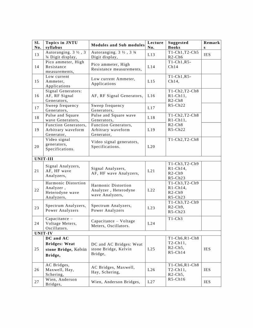

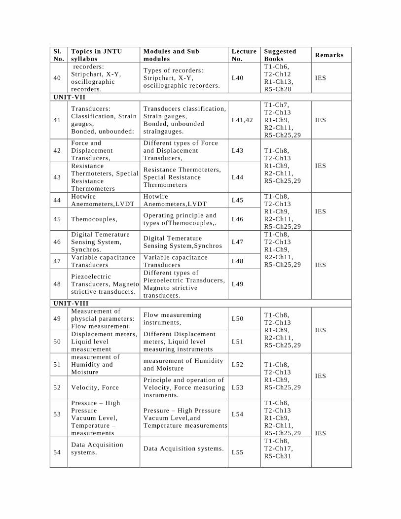
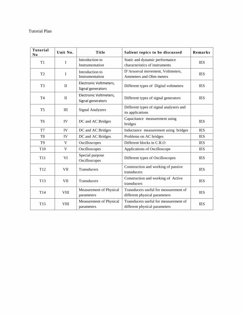

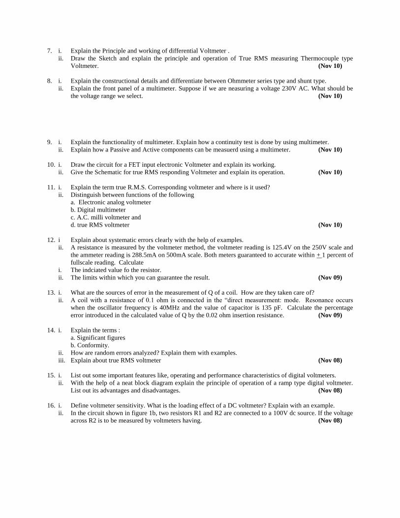
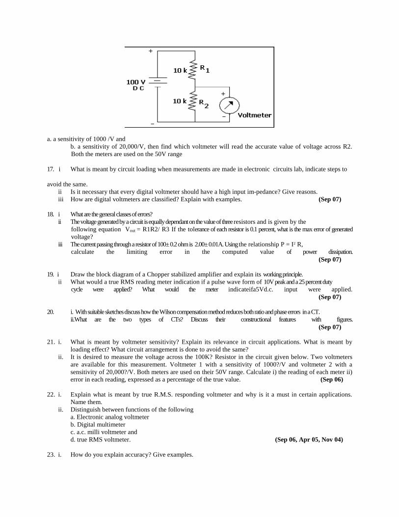


![Superintegrable Lissajous systems on the sphere · 2018-10-09 · arXiv:1404.7064v1 [math-ph] 28 Apr 2014 Superintegrable Lissajous systems on the sphere J.A. Calzada1, S¸.Kuru2,](https://static.documents.pub/doc/80x56/5f21c1bc50d86527771350ec/superintegrable-lissajous-systems-on-the-sphere-2018-10-09-arxiv14047064v1-math-ph.jpg)


