NSRLTN10004 1 November 2010 Beam Degrader Wheel for Gold Beams at NSRL Version 1.0 Jesse Fite, Seth Nemesure, Michael Sivertz, Adam Rusek, IHung Chiang The NSRL Binary Filter is used to measure the beam energy of heavily ionizing ions by degrading the beam in polyethylene (PE) of thicknesses up to 26 cm. The finest gradation is 0.25 mm. When we are running Gold ions at energies of 100 to 200 MeV/nucleon, the range is quite short; 2 to 7 mm in PE. In order to obtain good energy resolution, we require gradations in PE that are 0.1 mm or finer. During the NSRL Runs 10A and 10B, we made a degrader system that was mounted manually on the ion chambers used for Gold beam. These degraders are described in NSRLTN10002 . The finest step size was 0.025 mm of PE. Although this system gave a good high resolution measure of the Gold beam energy, the time required to change degraders had a severe impact on the experimental running schedule. We wanted to automate the degrader change to make more efficient use of the beam time. Several designs were considered, and the choice was made to select a pair of degrader wheels, each with 10 possible degrader settings. The “coarse” wheel included degrader thicknesses from 0 to 9 mm in 1 mm steps. The “fine” wheel also had 10 settings from 0.0 to 0.9 mm in 0.1 mm steps. This allowed us to select polyethylene degrader in any thickness from 0.1 to 9.9 mm in 0.1 mm steps. The two wheels are driven by stepper motors of the same type used in all of the NSRL applications, to simplify software control. And like the other NSRL stepper motor controllers, it is operated using a simple GUI to control the stepper motors. The user interface is shown in Figure 1. It can be adjusted by either typing a number between 0.0 and 9.9 in the window box, or by using the two sliders to select the combination of the two wheel settings that will give the desired degrader thickness. There is also a “HOME” button that will cause the two wheels to rotate until they come into contact with their microswitches. Currently there is significant inertia in the wheels causing an overrun of the home switches. Until this overrun is fixed, the user is dissuaded from using it except when the wheel orientation is completely lost. It is recommended that the “HOME” function be combined with an access to align the two wheels by hand at the 0,0 position. Access to the GUI is currently via the STARTUP Utility, start Commissioning NSRL Stepper (Rotational Filter Support). Selecting the NSRL Stepper opens a separate window for nsrlStepper. From this window, the user can pull down the
Transcript
NSRL-‐TN-‐10-‐004 1 November 2010
Beam Degrader Wheel for Gold Beams at NSRL
Version 1.0
Jesse Fite, Seth Nemesure, Michael Sivertz, Adam Rusek, I-‐Hung Chiang
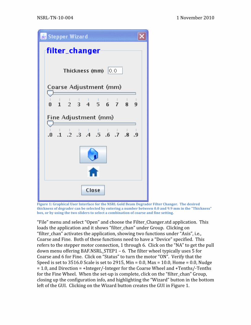
The NSRL Binary Filter is used to measure the beam energy of heavily ionizing ions by degrading the beam in polyethylene (PE) of thicknesses up to 26 cm. The finest gradation is 0.25 mm. When we are running Gold ions at energies of 100 to 200 MeV/nucleon, the range is quite short; 2 to 7 mm in PE. In order to obtain good energy resolution, we require gradations in PE that are 0.1 mm or finer. During the NSRL Runs 10A and 10B, we made a degrader system that was mounted manually on the ion chambers used for Gold beam. These degraders are described in NSRL-‐TN-‐10-‐002. The finest step size was 0.025 mm of PE. Although this system gave a good high resolution measure of the Gold beam energy, the time required to change degraders had a severe impact on the experimental running schedule. We wanted to automate the degrader change to make more efficient use of the beam time. Several designs were considered, and the choice was made to select a pair of degrader wheels, each with 10 possible degrader settings. The “coarse” wheel included degrader thicknesses from 0 to 9 mm in 1 mm steps. The “fine” wheel also had 10 settings from 0.0 to 0.9 mm in 0.1 mm steps. This allowed us to select polyethylene degrader in any thickness from 0.1 to 9.9 mm in 0.1 mm steps. The two wheels are driven by stepper motors of the same type used in all of the NSRL applications, to simplify software control. And like the other NSRL stepper motor controllers, it is operated using a simple GUI to control the stepper motors. The user interface is shown in Figure 1. It can be adjusted by either typing a number between 0.0 and 9.9 in the window box, or by using the two sliders to select the combination of the two wheel settings that will give the desired degrader thickness. There is also a “HOME” button that will cause the two wheels to rotate until they come into contact with their microswitches. Currently there is significant inertia in the wheels causing an overrun of the home switches. Until this overrun is fixed, the user is dissuaded from using it except when the wheel orientation is completely lost. It is recommended that the “HOME” function be combined with an access to align the two wheels by hand at the 0,0 position. Access to the GUI is currently via the STARTUP Utility, start Commissioning NSRL Stepper (Rotational Filter Support). Selecting the NSRL Stepper opens a separate window for nsrlStepper. From this window, the user can pull down the
NSRL-‐TN-‐10-‐004 1 November 2010
Figure 1: Graphical User Interface for the NSRL Gold Beam Degrader Filter Changer. The desired thickness of degrader can be selected by entering a number between 0.0 and 9.9 mm in the "Thickness" box, or by using the two sliders to select a combination of coarse and fine setting.
“File” menu and select “Open” and choose the Filter_Changer.std application. This loads the application and it shows “filter_chan” under Group. Clicking on “filter_chan” activates the application, showing two functions under “Axis”, i.e., Coarse and Fine. Both of these functions need to have a “Device” specified. This refers to the stepper motor connection, 1 through 6. Click on the “NA” to get the pull down menu offering BAF.NSRL_STEP1 – 6. The filter wheel typically uses 5 for Coarse and 6 for Fine. Click on “Status” to turn the motor “ON”. Verify that the Speed is set to 3516.0 Scale is set to 2915, Min = 0.0, Max = 10.0, Home = 0.0, Nudge = 1.0, and Direction = +Integer/-‐Integer for the Coarse Wheel and +Tenths/-‐Tenths for the Fine Wheel. When the set-‐up is complete, click on the “filter_chan” Group, closing up the configuration info, and highlighting the “Wizard” button in the bottom left of the GUI. Clicking on the Wizard button creates the GUI in Figure 1.
NSRL-‐TN-‐10-‐004 1 November 2010
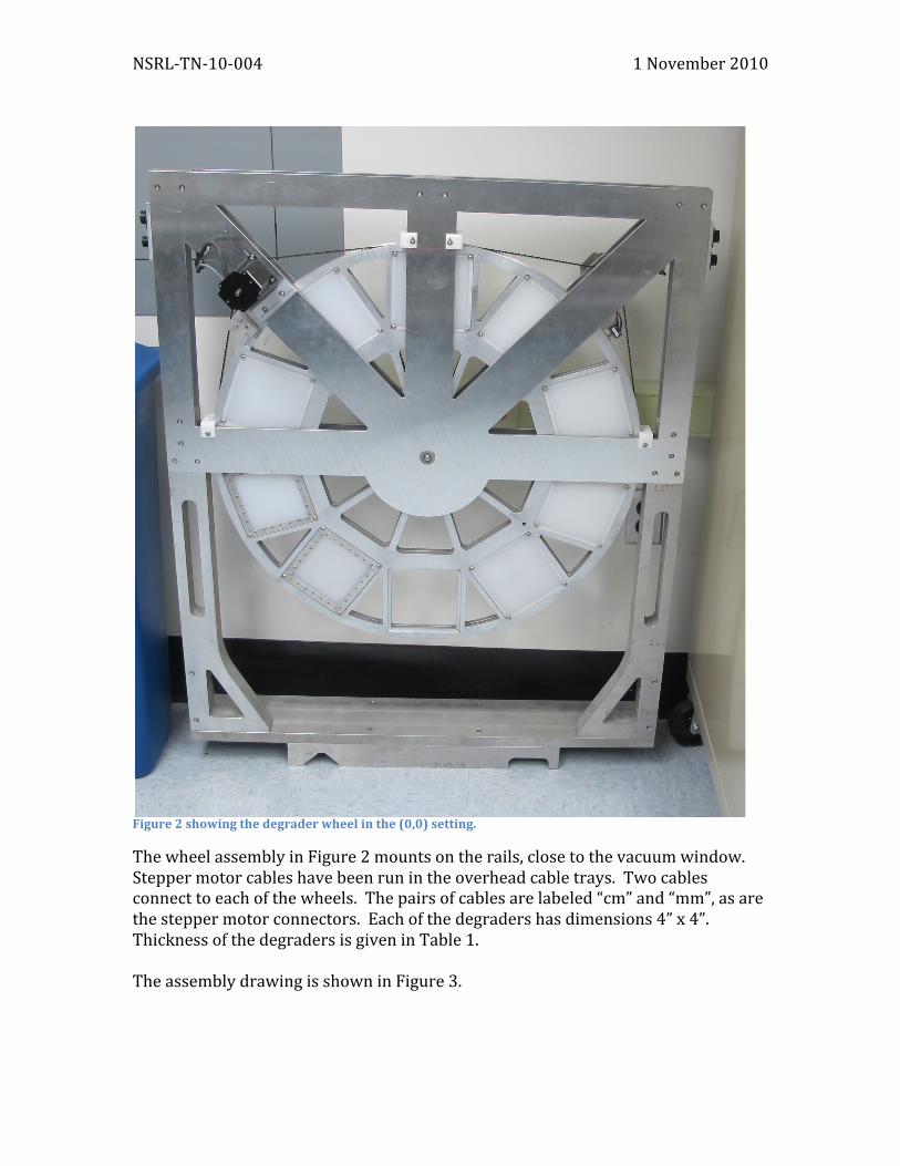
Figure 2 showing the degrader wheel in the (0,0) setting.
The wheel assembly in Figure 2 mounts on the rails, close to the vacuum window. Stepper motor cables have been run in the overhead cable trays. Two cables connect to each of the wheels. The pairs of cables are labeled “cm” and “mm”, as are the stepper motor connectors. Each of the degraders has dimensions 4” x 4”. Thickness of the degraders is given in Table 1. The assembly drawing is shown in Figure 3.
NSRL-‐TN-‐10-‐004 1 November 2010
Figure 3: Assembly drawing of the degrader wheel.
The degraders were manufactured out of thin sheets of polyethylene. Each degrader is 4” x 4” across. All of the fine gradations were made up by putting together several sheets of thin polyethylene stock. The stock sheets were of thickness 0.1, 0.2 and 0.5 mm, nominally. These were combined to make all of the submillimeter degraders. The 1 and 2 mm thick degraders were made from 1 mm thick stock. All the thicker degraders, 3-‐9 mm, were machined from thicker stock. The thickness of the stock was measured using a micrometer. The density was checked by weighing samples of known dimension to compute the average density. For the thinnest sheets, we use the manufacturer’s nominal density of 0.91 g/cm3 rather than our measured density because uncertainty in the thickness measurement is large. In general, the thin sheets had densities of 0.91 g/cm3, while the thicker polyethylene was 0.92 g/cm3. Using these values of density, and the measured thickness of each sample, we derive the areal density of each of the degraders. Also listed in Table 1 is the uncertainty in the measured thickness, as computed from the standard deviation of thickness measurements at a minimum of 9 points around the circumference of the sheet.
7
A
8
B
C
D
6 5
7
G
E
F
NOTES:
H
8 6 5
24 3 1
A
DW
G N
OR E V
SH
TO
F
C
D
2 4 3
G
E
F
1
H
PRO/E
!"##$%&'()!!&#&')*"'+%&,)'*-&.*
SCALE:
DRAWING NUMBER:
FINISHAPPLICATION
CATEGORYQ.A.
UNLESS OTHERWISE SPECIFIED
DIMENSIONS ARE IN INCHES
USED ON DRAWING NO. QTY. PER ASS'Y.BREAK SHARP EDGES
ANGULAR TOLERANCE 1
DECIMAL TOLERANCES.X .030
.XX .015.XXX .005
ACCORDANCE WITHANSI/ASME Y14.54M-1994
BY
SUPERVISORAPPROVAL
DESIGNAPPROVAL
CHECKEDBY
ENGINEERAPPROVAL
DRAWN
INTERPRET IN GENERAL
ESIZE
SHEET OFWEIGHT:
/,*".0+.121+33456
REV.
.03 MAX. MIN. 015
7'""89):&.+.)*$".)#+#)7"')*"'2
A-3
A
A
3405
040
1
1
REVISION APPROVALS
SUPVENGDESCHKBYDATEDESCRIPTIONECN NO.REV
------INITIAL RELEASE-A
NSRLFILTER CHANGER
Filter Changer Assy.
34050400.500
J. FITE 17-Sep-10
1
BILL OF MATERIALS
REMARKSDESCRIPTIONPART NUMBERITEMNUMBERQTY
ANAHEIM AUTOMATIONHIGH TORQUE STEPPER MOTOR, NEMA 2323L310D-LW812
IT SWITCHESMICROSWITCH, SHORT LEVER16-410 / 76-122022
MC MASTER CARRSCREW,SOC.HD,.164-32X.75, SST92185A19738
MCMASTER CARRRETAINING RING, .375 DIA, E STYLE98408A13442
MCMASTER CARRSCR. SOC. BUTT. HD. .112-40 X .38 LG. SST92949A10858
MCMASTER CARRSCREW, BUTT HD, .190-24 X 50, SST92949A242620
There are some anomalies in the degrader thicknesses. Note that accumulating errors in thickness lead to a “0.9 mm” nominal degrader that is really 1.049 mm thick. Conversely the “1.0 mm” nominal degrader is slightly thinner at 0.995 mm measured.