CHAPTER 9-1 Converged Plantwide Ethernet (CPwE) Design and Implementation Guide OL-21226-01, ENET-TD001E-EN-P 9 CIP Sync Sequence of Events Introduction This chapter describes the implementation of CIP Sync time synchronization on EtherNet/IP and extends the design recommendations described in Chapter 3, “CPwE Solution Design—Cell/Area Zone,” and Chapter 5, “Implementing and Configuring the Cell/Area Zone.” The main purpose for Cell/Area IACS device time synchronization is to enable consistent and accurate event timestamping. This requirement is common within Cell/Area zone manufacturing applications such as sequence of events, first fault detection, and distributed CIP Motion applications (Chapter 8, “CIP Motion.”). To support this, the Cell/Area IACS network infrastructure must be capable of two main tasks: • Managing time synchronization services • Delivering data between Cell/Area IACS devices in a timely manner As noted in earlier chapters, the Cell/Area zone is where the Industrial Automation and Control System (IACS) end-devices connect into the Cell/Area IACS network. Careful planning is required to achieve the optimal design and performance from both the Cell/Area IACS network and IACS device perspective. This extension of the CPwE architectures focuses on EtherNet/IP, which is driven by the ODVA Common Industrial Protocol (CIP) (see IACS Communication Protocols, page1-26), and in particular is tested with Rockwell Automation devices, controllers, and applications. CIP Sync uses the CIP application layer protocol and the IEEE 1588-2008 precision time protocol (PTP) standard for time synchronization. CIP Sync IEEE 1588-2008 is designed for local systems requiring very high accuracies beyond those attainable with Network Time Protocol (NTP). To read more about CIP Sync device configuration and capabilities, see the Rockwell Automation publication IA-AT003, “Integrated Architecture and CIP Sync Configuration and Application Technique”, at the following URL: http://literature.rockwellautomation.com/idc/groups/literature/documents/at/ia-at003_-en-p.pdf This chapter outlines the key requirements and technical considerations for CIP Sync time synchronization between IACS devices within the Cell/Area zone.This chapter covers the following: • Sequence of Events concepts • Precision Time Protocol Overview • Cell/Area Zone CIP Sync Architectures • Design Recommendations and Considerations for CIP Sync
Transcript
Converged Plantwide Ethernet (CPw
OL-21226-01, ENET-TD001E-EN-P
C H A P T E R 9
CIP Sync Sequence of Events
IntroductionThis chapter describes the implementation of CIP Sync time synchronization on EtherNet/IP and extends the design recommendations described in Chapter 3, “CPwE Solution Design—Cell/Area Zone,” and Chapter 5, “Implementing and Configuring the Cell/Area Zone.” The main purpose for Cell/Area IACS device time synchronization is to enable consistent and accurate event timestamping. This requirement is common within Cell/Area zone manufacturing applications such as sequence of events, first fault detection, and distributed CIP Motion applications (Chapter 8, “CIP Motion.”). To support this, the Cell/Area IACS network infrastructure must be capable of two main tasks:
• Managing time synchronization services
• Delivering data between Cell/Area IACS devices in a timely manner
As noted in earlier chapters, the Cell/Area zone is where the Industrial Automation and Control System (IACS) end-devices connect into the Cell/Area IACS network. Careful planning is required to achieve the optimal design and performance from both the Cell/Area IACS network and IACS device perspective. This extension of the CPwE architectures focuses on EtherNet/IP, which is driven by the ODVA Common Industrial Protocol (CIP) (see IACS Communication Protocols, page1-26), and in particular is tested with Rockwell Automation devices, controllers, and applications.
CIP Sync uses the CIP application layer protocol and the IEEE 1588-2008 precision time protocol (PTP) standard for time synchronization. CIP Sync IEEE 1588-2008 is designed for local systems requiring very high accuracies beyond those attainable with Network Time Protocol (NTP). To read more about CIP Sync device configuration and capabilities, see the Rockwell Automation publication IA-AT003, “Integrated Architecture and CIP Sync Configuration and Application Technique”, at the following URL: http://literature.rockwellautomation.com/idc/groups/literature/documents/at/ia-at003_-en-p.pdf
This chapter outlines the key requirements and technical considerations for CIP Sync time synchronization between IACS devices within the Cell/Area zone.This chapter covers the following:
• Sequence of Events concepts
• Precision Time Protocol Overview
• Cell/Area Zone CIP Sync Architectures
• Design Recommendations and Considerations for CIP Sync
Technology OverviewTimestamping is critical in many industrial applications. For example, sub-millisecond timestamps are common requirements in the power industry, where the sequence and timing of events is critical. These event and timestamps can be captured by dedicated I/O modules that are designed for this purpose, timestamping relays, or many other accurate time-based devices. This device-based timestamping can provide an extremely accurate time resolution for SOE applications. In the power industry, SOE modules are often connected to electrical breakers that help produce and distribute power to the grid. Because of the extremely fast response time of these breakers, highly accurate timestamps of the event are necessary to recreate the cause of a system failure.
Industries in which SOE is important include the following:
• The pharmaceutical industry requires a precise audit trail. Part of this trail requires an ability to accurately identify when operators performed actions and when control systems responded, to provide a very accurate picture of the sequence of events.
• Supervisory Control and Data Acquisition (SCADA) applications require accurate timestamps that may cross many time zones. For example, a pipeline with multiple pumping stations may require timestamps from multiple time zones for consolidation into a common time reference. In these applications, a master time source (such as a GPS) is often required to coordinate clocks for timestamping.
SOE Applications—Traditional vs. CIP Sync Approach
This section describes the traditional methods for time synchronization vs. the methods used when CIP Sync is implemented.
Traditional Approach to Time Synchronization
The traditional approach to handling real-time control for an SOE application is to timestamp events at the controller or at a computer. As shown in Figure 9-1, rate control system components are not time-synchronized, so all timestamp alarming is done either at the controller level or at the computer. The time source in this case is a Network Time Protocol (NTP) server.
9-2Converged Plantwide Ethernet (CPwE) Design and Implementation Guide
OL-21226-01, ENET-TD001E-EN-P
Chapter 9 CIP Sync Sequence of Events
Technology Overview
Figure 9-1 Real-time Control System
An advantage to using this type of solution is that the input device can communicate with the control system using any type of physical network control media (for example, the Remote I/O, ControlNet, DeviceNet, Profibus, Modbus, or Foundation Fieldbus networks). A disadvantage to using this type of system is the event timestamping resolution. If event timestamping is done in the NTP Client PC database, located at the enterprise level of the network, its resolutions may be no better than 1 second because of input device hardware delays, controller program scan time, and network latency. Timestamp resolution can be improved by timestamping at the controller, located in the control level, ranging from 100–500 ms, but the same kind of time delays are still a factor (with the exception of network delays experienced in the enterprise level).
To improve event timestamping resolution and reliability, some control system manufacturers have created control systems and input devices that are time-synchronized on the Ethernet network, as shown in Figure 9-2. The synchronization mechanism is a master/slave relationship. The device designated as the time master (M) sends packets of time data via the Ethernet network to the devices designated as slaves (S) in an effort to synchronize to the master device time. This enables the control system to timestamp multiple events scattered across multiple controllers or input devices to a sub-microsecond (μs) resolution.
2902
55
EthernetSwitch
NTP Client PCDatabase
NTP Server PCReal Time Source
ControlSystem
C
ControlSystem
B
ControlSystem
A
Digital InputModules
Digital InputModules
Other ControlNetwork Media
EnterpriseLevel
ControlLevel
Digital InputModules
Digital InputModules
Digital InputModules
Digital InputModules
Event TimeStamping
done here.
9-3Converged Plantwide Ethernet (CPwE) Design and Implementation Guide
OL-21226-01, ENET-TD001E-EN-P
Chapter 9 CIP Sync Sequence of Events
Technology Overview
Figure 9-2 Real-time SOE Control System Synchronized on the Ethernet Network.
These control systems may be time-synchronized using a non-standard, modified version of the network stack, which makes these products and Ethernet networks proprietary because of the modifications made below the application layer. (See Figure 9-3.) This means these systems may not be easily adapted to a standard Ethernet network. As well, standard network devices may be difficult to integrate, significantly reducing the value of the network.
CIP Sync: Using EtherNet/IP and Precision Time Protocol for Real-Time Synchronization
EtherNet/IP is designed to maintain the standards and common protocols typically associated with Ethernet installations and applications. In fact, the Common Industrial Protocol (CIP) is an application that resides at the application layer and is portable enough to be used by EtherNet/IP, DeviceNet, ControlNet, and CompoNet networks, facilitating backward and forward compatibility. In addition to the CIP protocol, CIP Sync uses the IEEE 1588 Precision Time Protocol (PTP), which can use standard Ethernet TCP/IP technologies. (See Figure 9-4). CIP Sync and PTP allow real-time SOE timestamping control based upon standard network technologies. Network infrastructure that
2902
56
EthernetSwitch
ControlSystem
B
ControlSystem
A
Digital InputModules
EthernetSwitch
Digital InputModules
Event TSdone here.
Event TSdone here.
S
S
S
M
Database
System Synched
Digital InputModules
EthernetSwitch
Digital InputModules
S S
2902
57
IP
H/W Support withSwitching
Technology
Application Layer
TCP/UDP ModifiedStack
IP
StandardEthernetController
Application Layer
Switch
TCP/UDP ModifiedStack
9-4Converged Plantwide Ethernet (CPwE) Design and Implementation Guide
OL-21226-01, ENET-TD001E-EN-P
Chapter 9 CIP Sync Sequence of Events
Technology Overview
supports PTP enables higher levels of precision, is easily integrated into other standard networks and supports devices that do not support PTP. This open support and integration capability are key advantages of this approach.
Figure 9-4 CIP Sync Uses Standard Network Stack Implementation
EtherNet/IP uses CIP Sync to synchronize device clocks on the Ethernet network. CIP Sync is the name given to time synchronization services for the Common Industrial Protocol (CIP). CIP Sync uses the IEEE 1588 “Standard for a Precision Clock Synchronization Protocol for Networked Measurement and Control Systems”, referred to as Precision Time Protocol (PTP), to synchronize devices to a very high degree of accuracy.
The IEEE 1588 standard specifies a protocol to synchronize independent clocks running on separate nodes of a distributed control system to a high degree of accuracy and precision. The clocks communicate with each other over a communication network. In its basic form, the protocol is intended to be administration-free. The protocol generates a master-slave relationship among the clocks in the system. Within a given subnet of a network, there is a single master clock. All clocks ultimately derive their time from a clock known as the grandmaster clock.
A sync message is sent periodically by any port associated with a clock claiming to be the master clock. All ports use the same algorithm, termed the best master clock algorithm. If a port of a master clock receives a Sync message from a better clock, that clock ceases to claim to be a master and the receiving port assumes the status of a slave. Likewise, if a clock with a port acting as a slave determines that it would make a better master than the current master clock, it assumes the status of master and begins to send Sync messages. Some nodes may be implemented as slave only and never assume mastership (for example, an I/O device).
CIP Sync encapsulates the IEEE 1588 protocol, which measures network transmission latencies and corrects for infrastructure delays. The result is the ability to synchronize distributed clocks to within hundreds of nanoseconds of accuracy. Once all the clocks in a control system share a synchronized, common understanding of system time, and have been synchronized to within +/-100 ns, events being monitored in the control system (for example, the ControlLogix system) can be timestamped to a very high degree of accuracy.
A PTP system of distributed clocks consists primarily of ordinary clocks, boundary clocks and/ or transparent clocks. One clock in the system is selected as the grandmaster clock. In this case, the switch is the grandmaster clock in the system. This selection is automatically made by other clocks in the system by examining information contained in the sync message.
2901
24
Application Layer
File T
rans
fer
Email
Web
Voice/
Video
Serve
rs
Man
agem
ent
Transport Layer
Network Layer
Data Link Layer
Physical LayerIEEE 802.3
TCP/IP Suite
Application Layer FTP SMTP HTTP
IP
CSMA/CD
Physical Layer
Standard
VOIP DNS SNMP
TCP UDP
9-5Converged Plantwide Ethernet (CPwE) Design and Implementation Guide
OL-21226-01, ENET-TD001E-EN-P
Chapter 9 CIP Sync Sequence of Events
Technology Overview
Figure 9-5 shows a typical configuration.
Figure 9-5 Sample System with Grandmaster, Boundary, Transparent, and Slave Clocks
To read more about 1588 PTP (Precision Time Protocol and Synchronizing Mechanism), see the Rockwell Automation publication A-AT003A-EN-P, Integrated Architecture and CIP Sync Application Technique.
This and other reference documents can be found on the Rockwell Automation Literature Library at the following URL: http://www.rockwellautomation.com/literature.
2916
17
GPSGrand Master
TimeSlave
Switch withBoundary Clock
functions
Switch
TimeSlave
TimeSlave
Switch withBoundary Clock
functions
TimeSlave
TimeSlave
TimeSlave
TimeSlave
M
S
M M
GM
S
S
S
MMM
SS S
SS
M
TimeSlave
TimeSlave
TC TC TC
TC
9-6Converged Plantwide Ethernet (CPwE) Design and Implementation Guide
This section describes Rockwell Automation products that support real-time synchronization, and explains the differences between PTP and ControlLogix clock synchronization mechanisms.
Rockwell Automation Devices That Support CIP Sync
These Rockwell Automation Logix devices support CIP Sync and are discussed in this document:
• 1756-L6x and 1756-L7x controllers, version 18 and later
These modules are the Programmable Automation Controllers (PAC) of the ControlLogix family. These controllers support the CIP Sync Object, firmware revision v18 and above, and can be configured as a time source and/ or a 1588 PTP (v2) grandmaster (GM) of time on the Ethernet network.
• 1756-EN2T and 1756 1756-EN2TR modules
These are Ethernet bridge modules for the Control Logix family and support the 1588PTP (v2) CIP Sync Object firmware revision V3.0 and above. These Ethernet modules are configured as boundary clocks by default and propagate UTC time to and from the PAC controller, digital I/O that reside in the same chassis, and the Ethernet network.
• 1756-IB16ISOE and 1732E-IB16M12SOEDR modules
These are digital input modules that support the 1588PTP(v2) CIP Sync Object and are specifically designed for sequence of events (SOE) applications, firmware revision V2.7 and above. They are capable of returning timestamps with worst-case accuracy for all 16 points of 50 microseconds. The modules also have the ability to buffer up to 160 I/O point transitions locally to alleviate burst conditions that might otherwise cause data loss at the controller when multiple transitions occur in a short time frame. The SOE module returns timestamps for each I/O point transition as a 64-bit number (two 32-bit words).
• 1756HP-Time module
This is a GPS module that acquires GMT time from a group of satellites and can be used as the Real Time Source. With the addition of an embedded two port Ethernet switch that supports a Device Level Ring (DLR) topology and the 1588 PTP (v2) CIP Sync Object, the module can be configured as the grandmaster of time on the Ethernet network.
The module can be configured as a PTP (GM) and/or an NTP Server. The module is manufactured by HiProm Inc. (http://www.hiprom.com/).
• Stratix 8000 and Stratix 8300 Switch—The Stratix 8000 is a Layer 2 Ethernet managed switch. The Stratix 8300 is a Layer 2 and Layer 3 Ethernet managed switch with traffic routing capabilities. Both switches are based on Cisco technology.
These modular, managed switches use the current Cisco Catalyst switch architecture and feature set, along with powerful configuration tools. These features provide secure integration with the enterprise network, using tools familiar to IT professionals.
The 1783-MS10T Stratix 8000 Ethernet managed switch base unit supports the 1588PTP(V2) protocol and can be configured in Transparent Clock mode, Boundary Clock mode, or Forward mode per port for the propagation of PTP packets from one port to another.
Note The 1783-MX08T copper and 1783- MX08F fiber expansion modules do not support and cannot be configured for Transparent Clock or Boundary Clock modes, but will forward PTP traffic in v6 of Cisco IOS Software.
9-7Converged Plantwide Ethernet (CPwE) Design and Implementation Guide
Now apply CIP Sync to a real time ControlLogix system. As shown in Figure 9-6, system time is passed at a 1-second interval from the grandmaster (GM) controller (L6x), through the 1756-EN2TR module configured as a boundary clock, to all slave (S) devices on the Ethernet network. The slave device clocks are now synchronized to within +/- 100 nanoseconds. This level of synch resolution enables the system to timestamp events to the 1 -microsecond resolution. Because the clocks are all synchronized, this allows precise correlation of those events that occur within the PTP network. Once the events have been timestamped (TS) by the SOE input modules, the timestamped events are sent to a database running on a PC higher in the architecture via the controller. If multiple L6x controllers are installed in the system, the controllers Wall Clock Times (WCT) are synchronized as well.
Figure 9-6 Rockwell Automation Real-Time SOE Control System on the EtherNet/IP Network
Difference between the 1588 PTP and ControlLogix Clock Synchronization Resolution
Historically, the ControlLogix backplane has used a mechanism called Coordinated System Time (CST) to synchronize modules across the backplane. This clock has a resolution of 1 microsecond of accuracy, and was used to synchronize motion, and also to synchronize the 1756-IB16SOE sequence of events modules with the ControlLogix controller.
As the IEEE 1588 PTP protocol has been layered into this architecture, the translation of time from the ControlLogix backplane to a PTP implementation is managed via the EtherNet/IP modules. (These include the 1756-EN2T, 1756-EN2TR, 1756-EN3T and 1756-EN3TR modules.) Although strictly speaking, a boundary clock is defined as one module with two PTP ports, the meaning of that definition is extended to include the ControlLogix EtherNet/IP modules, which translate time from
2902
61
Event TSdone here.
Database
EN2TR
L6X
SOE
DOUT
EN2TR
SOE L
6X
Event TS done here.
CLXChassis #1
CLXChassis #2
1732E-IB16M12SOEDR
Armor Block I/O #2
1732E-IB16M12SOEDR
Armor Block I/O #1
Stratix 8000
Stratix 8000
SS
S SGM
ControllerClocks Synched
ControllerClocks Synched
9-8Converged Plantwide Ethernet (CPwE) Design and Implementation Guide
OL-21226-01, ENET-TD001E-EN-P
Chapter 9 CIP Sync Sequence of Events
Technology Overview
CST to PTP and back again. For any time system that uses a path through the ControlLogix backplane, time accuracy and resolution is only as accurate as the clock that has the least accuracy or resolution—which, in this case, is 1 μs. (See Figure 9-7.)
Figure 9-7 The Control Logix Backplane Has a Synchronization Resolution of +/- 1μs.
Another implementation for setting up time in the system is to use the 1756HP-Time module. The 1756HP-Time module is a GPS module capable of acting as the real-time source and grandmaster of the Ethernet network. In this situation, system time is sent across the network first via the Ethernet port on the front of the GPS module. The 1756-EN2TR modules, which act as boundary clocks, receive time from the GPS module via the Ethernet infrastructure, and then pass system time into the ControlLogix backplane. System time is distributed to all SOE modules, 1756-L6x and 1756-L7x controllers, and other 1756-EN2TR modules across the backplane. (See Figure 9-8).
2902
63
EN2TR
L6X
SOE
DOUT
EN2TR
SOE L
6X
CLXChassis
#1
Clocks on the Networkare synchronized to+/- 100 Nanosecond
Resolution
Clocks on the ControlLogixbackplane are synchronized to a
sub-Microsecond Resolution
CLXChassis
#2
CLXChassis
#3
1732E-IB16M12SOEDR
Armor Block I/O #3
1732E-IB16M12SOEDR
Armor Block I/O #1
Stratix 8000
S
1732E-IB16M12SOEDR
Armor Block I/O #2
SS
S
S
GM
EN2TR
SOE L
6X
SM
S SMS S SM
System TimeSource
BoundryClock
BoundryClock
BoundryClock
9-9Converged Plantwide Ethernet (CPwE) Design and Implementation Guide
OL-21226-01, ENET-TD001E-EN-P
Chapter 9 CIP Sync Sequence of Events
Sequence of Events (SOE) Reference Architecture Testing
Figure 9-8 SOE Control System with a 1756HP-Time (GPS) Module Used as the Real-Time Source and the Grandmaster of the Ethernet Network
Sequence of Events (SOE) Reference Architecture Testing
Testing SOE applications measured the performance of Rockwell Automation products that support CIP Sync.
The goals of CIP Sync reference architecture testing are as follows:
• Characterize system performance of a CIP Sync SOE control system using 1588 PTP devices such as the 1756-L6x and/or L7x controllers, 1756-EN2TR, 1783-ETAP, 1756-IB16ISOE, and 1732E-IB16M12SOEDR modules
• Verify SOE time accuracy in a variety of network scenarios
• Provide recommended network architectures for Rockwell Automation customers using CIP Sync
• Conduct CIP Sync testing to deploy PTP within the cell/area zone in Layer 2 architectures as well as distribution of time in Layer 3 topology.
2902
64
EN2TR
L6X
SOE
GPS
EN2TR
SOE L
6XCLX
Chassis#1
Clocks on the Networkare synchronized to+/- 100 Nanosecond
Resolution
Clocks on the ControlLogixbackplane are synchronized to a
sub-Microsecond Resolution
CLXChassis
#2
CLXChassis
#3
1732E-IB16M12SOEDR
Armor Block I/O #3
1732E-IB16M12SOEDR
Armor Block I/O #1
Stratix 8000
S
1732E-IB16M12SOEDR
Armor Block I/O #2
SS
S
SGM
EN2TR
SOE L
6X
SS
M S SMS S SM
SystemTime
Source
BoundryClock
BoundryClock
BoundryClock
9-10Converged Plantwide Ethernet (CPwE) Design and Implementation Guide
OL-21226-01, ENET-TD001E-EN-P
Chapter 9 CIP Sync Sequence of Events
Sequence of Events (SOE) Reference Architecture Testing
Test Criteria
The purpose of the test is to measure the event timestamp difference between the grandmaster SOE device and the slave SOE devices as the CIP Sync PTP packets pass through the network infrastructure. Test data to be collected includes the following:
• 1756-IB16ISOE module timestamp accuracy
• 1732E-IB16M12SOEDR module timestamp accuracy
• Switch latency and network delay calculation (by extrapolating the SOE event timestamp data collected)
Testing is divided into three phases.
Phase I of the test has minimal 1756-EN2TR module or network loading. This test collects SOE timestamp data in the best-case scenario to establish a baseline for all future testing. These timestamps are compared with each other to determine how close these devices are synchronized. The only 1756-EN2TR loading is the SOE modules, I/O connection, and data coming to and from the Logix controller. No additional I/O Class 1 or 3 traffic is generated.
This test helps establish a timestamping, best-case scenario baseline for all future testing.
Phase 2 of the test adds load to both the 1756-EN2TR modules and the network in the form of class1 I/O produce/consume (P/C) multicast data traffic. P/C data traffic refers to a method of transferring data packets from one ControlLogix controller to another in the same network. The 1756-EN2TR module’s CPU utilization is loaded up to ~80 percent. (See Figure 9-9.)
Figure 9-9 Bi-directional Produce/Consume Messaging Traffic Between Controllers
This test helps determine whether any event timestamping degradation exists between devices when the 1756-EN2TR modules are loaded with traffic.
Phase 3 of the test adds additional loading to the 1756-EN2TR modules and to the network in the form of multicast and unicast traffic, generated by a traffic generator. The additional network loading is split into two groups. The first group of tests is conducted with a mixture of different types and sizes of network traffic. The second group of tests is conducted with only 1500-byte packets. The network traffic groups are tested at network traffic levels of 20 percent, 40 percent, and 60 percent for a total of six different tests. (See Figure 9-10.)
2902
65
EN2TR
L6X
SOE
DOUT
ControlLogixLocal Chassis #1
EN2TR
SOE L
6X
ControlLogixRemote Chassis #2
EN2TR
SOE L
6X
ControlLogixRemote Chassis #3
By-Direct. Produce/Consume MSG’s
By-Direct. Produce/Consume MSG’s
9-11Converged Plantwide Ethernet (CPwE) Design and Implementation Guide
OL-21226-01, ENET-TD001E-EN-P
Chapter 9 CIP Sync Sequence of Events
Sequence of Events (SOE) Reference Architecture Testing
Figure 9-10 Additional Network Loading Added by the Ixia Traffic Generator
This test helps determine whether there is any additional SOE event timestamping degradation between devices when the network is loaded down with different forms of traffic.
Calculating Chassis-based vs. Remote Modules Timestamping Accuracy
Timestamp (TS) data is collected from three 1756-IB16ISOE modules in the system. One 1756-IB16ISOE module resides in the local (GM) chassis and two additional 1756-IB16ISOE modules reside in their own remote chassis. The remote 1756-IB16ISOE module TS data is compared with the local (GM) 1756-IB16ISOE module TS data, and the time difference is calculated within the ControlLogix controller and logged into μs data groupings. These timestamp results are exported to an Excel spreadsheet for display. Figure 9-11 shows an example of how the timestamp data appears, along with the minimum, maximum, and average results.
The majority of the timestamp data captured ranges between no timestamp difference indicated by a value of zero to about 26 μs. A difference of zero means the device clock times were identical at the time of the event. A maximum timestamp difference of 64 μs was recorded, but the number of times it fell within this range was small enough (1–2 samples), that it did not register on the graph in Figure 9-11.
9-12Converged Plantwide Ethernet (CPwE) Design and Implementation Guide
OL-21226-01, ENET-TD001E-EN-P
Chapter 9 CIP Sync Sequence of Events
Sequence of Events (SOE) Reference Architecture Testing
Figure 9-11 Local/Remote 1756-IB16ISOE Timestamp Difference Test Results
Timestamp (TS) data is also collected from three 1732E-IB16M12SOEDR modules in the system. The 1732E-IB16M12SOEDR modules are directly connected to the Ethernet network. 1732E-IB16M12SOEDR module TS data is compared with the local (GM) 1756-IB16ISOE module TS data. The time difference is calculated within the ControlLogix controller and logged into μs data groupings. These timestamp results are exported to an Excel spreadsheet for display.
Figure 9-12 shows an example of how the timestamp data appears, along with the minimum, maximum, and average results. The majority of the timestamp data captured ranges between no timestamp difference indicated by a value in a range from zero to approximately 16 μs. A difference of zero means the device clock times were identical at the time of the event. A maximum timestamp difference of 50 μs was recorded, but the number of times it fell within this range was small enough (1-2 samples), that it did not register on the graph in Figure 9-12.
9-13Converged Plantwide Ethernet (CPwE) Design and Implementation Guide
OL-21226-01, ENET-TD001E-EN-P
Chapter 9 CIP Sync Sequence of Events
Sequence of Events (SOE) Reference Architecture Testing
Figure 9-12 Local 1756-IB16ISOE/Remote 1732E-IB16M12ISOEDR Timestamp Difference Test Results
The 1756-OB16D (DOUT) module resides in the local chassis and provides the output stimulus pulse for the 56SOE and 32SOE modules at a 100ms rate. The 24VDC DOUT output is wired to each SOE module, as shown in Figure 9-13. When the output module pulses, each SOE module’s 24V DC input records a timestamp (TS) value. These SOE (TS) values are then sent to the ControlLogix Controller for storage, as described previously.
9-14Converged Plantwide Ethernet (CPwE) Design and Implementation Guide
OL-21226-01, ENET-TD001E-EN-P
Chapter 9 CIP Sync Sequence of Events
Sequence of Events (SOE) Reference Architecture Testing
Figure 9-13 Diagram of the Output Stimulus and SOE Module Wiring
290269
ControlLogixLocal Chassis #1 ControlLogix
Remote Chassis #2
ControlLogixRemote Chassis #3
EN2TR
L6X
SOE
DOUT E
N2TR
SOE L
6X
EN2TR
SOE L
6X
Local56SOE-Rem56SOE1=56TSDiff_11
Local56SOE-Rem56SOE2=56TSDiff_12
Local56SOE-Rem32SOE1=32TSDiff_11
Local56SOE-Rem32SOE2=32TSDiff_12
Local56SOE-Rem32SOE3=32TSDiff_13
24VDC Output Pulse @100ms
Local 56SOE and Remote1 56SOETime Stamping Accuracy (A to B)
Min. 0uSec., Max. 64uSec., Ave. 8.64uSec.
0
1000
2000
3000
4000
5000
1 20 39 58
Time Stamp Diff (us)
Sam
ples
Col
lect
ed
Local 56SOE and Remote2 56SOETime Stamping Accuracy (A to C)
Min. 0uSec., Max. 53uSec., Ave. 8.43uSec.
0
1000
2000
3000
4000
5000
1 20 39 58
Time Stamp Diff (us)
Sam
ples
Col
lect
ed
Local 56SOE and Remote1 32SOETime Stamping Accuracy (A to D)
Min. 0uSec., Max. 50uSec., Ave. 6.51uSec.
0
1000
2000
3000
4000
5000
6000
1 20 39
Time Stamp Diff (us)
Sam
ples
Col
lect
ed
Local 56SOE and Remote2 32SOETime Stamping Accuracy (A to E)
Min. 0uSec., Max. 50uSec., Ave. 6.42uSec.
0
1000
2000
3000
4000
5000
6000
1 20 39
Time Stamp Diff (us)
Sam
ples
Col
lect
ed
Local 56SOE and Remote3 32SOETime Stamping Accuracy (A to F)
Min. 0uSec., Max. 49uSec., Ave. 6.67uSec.
0
1000
2000
3000
4000
5000
6000
1 20 39
Time Stamp Diff (us)
Sam
ples
Col
lect
ed
1732E-IB16M12SOEDR
Armor Block I/O #1
1732E-IB16M12SOEDR
Armor Block I/O #2
1732E-IB16M12SOEDR
Armor Block I/O #3
9-15Converged Plantwide Ethernet (CPwE) Design and Implementation Guide
OL-21226-01, ENET-TD001E-EN-P
Chapter 9 CIP Sync Sequence of Events
Sequence of Events (SOE) Reference Architecture Testing
Reference Architectures Test Results Summary
This section provides the test results for the reference architectures.
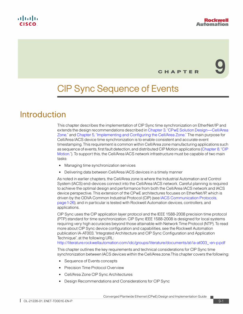
The Stratix 8000 switch was tested under different scenarios: as a boundary clock, a transparent clock and as a forwarding switch (where the switch simply forwards CIP Sync messages). The key objective of this test is to identify the impact of different PTP protocol options for the Stratix 8000 switch in a single network segment under a variety of network loads.
Figure 9-14 Star Topology Using the Stratix 8000 Switch with Transparent Clock
All 1588 PTP devices are connected in a star topology to a Stratix 8000 switch, which is a managed switch with full 1588 PTP time synchronization capabilities. This switch can be configured as transparent, boundary, or forward mode clocks. When the switch is configured as none of these clocks, the time sync messages are forwarded through the switch without any time compensation. This switch also provides quality of service (QoS) and Internet Group Management Protocol (IGMP) v2 capabilities, which are enabled by default.
2916
19
EN2TR
L6X
SOE
DOUT
EN2TR
SOE L
6X
1732E-IB16M12SOEDR
Armor Block I/O #3(F)
1732E-IB16M12SOEDR
Armor Block I/O #1(D)
Stratix 8000 #1
S
1732E-IB16M12SOEDR
Armor Block I/O #2(E)
SS
S
EN2TR
SOE L
6X
S
IXIA PC 1OUT
IXIA PC 1IN
Programming Terminal PanelView Plus
ControlLogixLocal Chassis #1
(A)
ControlLogixRemote Chassis #2
(B)
ControlLogixRemote Chassis #3
(C)
SGM
M
M MS S S S S
9-16Converged Plantwide Ethernet (CPwE) Design and Implementation Guide
OL-21226-01, ENET-TD001E-EN-P
Chapter 9 CIP Sync Sequence of Events
Sequence of Events (SOE) Reference Architecture Testing
The ControlLogix controller is the grandmaster (GM) of time and passes PTP packets to all CIP Sync slave (S; red dot) devices on the network.
The Ixia traffic generator is connected to the 1756-EN2TR Ethernet module port located in the Local ControlLogix chassis and introduces various types and sizes of Ethernet traffic to stress the network. The Ixia PC Ethernet traffic exits the Armor Block Ethernet port of 1732E-IB16M12SOEDR module number 3.
A three-phase test determines the SOE event timestamping accuracy between the GM device transmitting the time data and the slave devices receiving this time data.
A second series of tests is conducted using a Stratix 6000 switch, which is a managed switch with IGMP v2 capabilities, but with no 1588 PTP capabilities. A third series of tests is conducted using a Stratix 2000 switch, which is an unmanaged switch and has no 1588 PTP, QoS, or IGMP capabilities.
The fluctuation in SOE timestamp accuracy with different types of network traffic loading can be seen in Table 9-1and Figure 9-15.
Table 9-1 Star Topology SOE Timestamp Test Results
Test Revisions (μs)Stratix 8000 (Transparent)
Stratix 8000 (Boundary
Stratix 8000 (Forward) Stratix 6000 Stratix 2000
No Load Min
Max
Avg,
0
64
8.64
0
61
8.47
0
62
8.48
0
61
8.47
0
63
8.49
1756-EN2TR ~80% Loading
Min
Max
Avg,
0
64
8.44
0
67
8.48
0
59
8.49
0
64
8.53
0
65
8.51
Ixia traffic 20% Mixed Loading And 1756-EN2TR ~80% Loading
Min
Max
Avg,
0
63
8.45
0
62
8.83
0
64
8.47
0
69
8.53
0
63
8.55
Ixia traffic 40% Mixed Loading and 1756-EN2TR ~80% Loading
Min
Max
Avg,
0
68
8.48
0
63
8.46
0
68
8.53
0
63
8.52
0
69
8.62
Ixia traffic 60% Mixed Loading and 1756-EN2TR ~80% Loading
Min
Max
Avg,
0
60
8.45
0
60
8.50
0
68
8.78
0
66
8.71
0
70
8.81
Ixia traffic 20% 1500 Loading and 1756-EN2TR ~80% Loading
Min
Max
Avg,
0
65
8.43
0
62
8.48
0
143
36.96
0
149
39.06
0
145
40.14
Ixia traffic 40% 1500 Loading and 1756-EN2TR ~80% Loading
Min
Max
Avg,
0
65
8.45
0
60
8.48
0
124
49.47
0
128
51.57
0
137
51.41
Ixia traffic 60% 1500 Loading and 1756-EN2TR ~80% Loading
Min
Max
Avg,
0
63
8.46
0
65
8.47
0
117
46.23
0
116
48.10
0
137
49.37
9-17Converged Plantwide Ethernet (CPwE) Design and Implementation Guide
OL-21226-01, ENET-TD001E-EN-P
Chapter 9 CIP Sync Sequence of Events
Sequence of Events (SOE) Reference Architecture Testing
Figure 9-15 Star Topology SOE Timestamp Test Results
Test Observations
There is a minimal change in event timestamp accuracy (average ~2 μs difference) between the No Load, 1756-EN2TR ~80 percent loading, and the Ixia mixed traffic loading; with the maximum timestamp being (MAX = 70 μs) using the Stratix 2000 switch.
When the Ixia 1500-byte traffic was injected, there is a significant difference in event timestamp accuracy (average ~45 μs difference), with the maximum timestamp being (MAX = 137 μs) using the Stratix 2000 switch.
The 1500-byte packet traffic affected only the SOE modules that were in the direct path of the Ixia traffic stream (for example, the 1732E-IB16M12SOEDR module 3). The modules were affected only if the switch between the grandmaster and slave device was a managed switch configured for forward clock (for example, the Stratix 8000 switch); a managed switch with no PTP capability (for example, the Stratix 6000 switch); or an unmanaged switch that forwards all traffic (for example, the Stratix 2000 switch).
Conclusion
There was minimal timestamp degradation between the PTP devices until 1500-byte packets of data were introduced and the Stratix 8000 switch was configured for forward clock or used a switch with no PTP capabilities. For applications that require the highest degree of synchronization, it is recommended to use a managed switch with PTP capabilities, such as transparent or boundary clock modes.
9-18Converged Plantwide Ethernet (CPwE) Design and Implementation Guide
OL-21226-01, ENET-TD001E-EN-P
Chapter 9 CIP Sync Sequence of Events
Sequence of Events (SOE) Reference Architecture Testing
Figure 9-16 shows a diagram of the linear topology.
Figure 9-16 Linear Topology Using Embedded Dual-Port Ethernet Switch Devices with Transparent Clock
In this architecture, all 1588 PTP devices are connected in a linear topology. Each device is equipped with a dual-port Ethernet managed switch with 1588 PTP time synchronization capabilities. These capabilities include transparent clock mode. These switches also have QoS and IGMP v2 capabilities, which are enabled by default. Devices that do not support dual-port Ethernet switch technology are connected to the linear topology via the 1783-ETAP modules.
The ControlLogix controller is the grandmaster (GM) of time and passes PTP packets to all CIP Sync slave (S; red dot) devices on the network.
The Ixia computer is connected to the 1756-EN2TR module’s Ethernet port located in the local ControlLogix chassis and introduces various types and sizes of additional Ethernet traffic to stress the network. The Ixia computer Ethernet traffic exits the 1783-ETAP module 1 Ethernet port at the end of the physical network.
A three-phase test is conducted to determine the SOE Event timestamping accuracy between the GM device transmitting the time data and the slave devices receiving this time data.
2916
20
EN2TR
L6X
SOE
DOUT
EN2TR
SOE L
6X
1732E-IB16M12SOEDR
Armor Block I/O #3(F)
1732E-IB16M12SOEDR
Armor Block I/O #1(D)
1783-ETAP #21783-ETAP #1
S
1732E-IB16M12SOEDR
Armor Block I/O #2(E)
SS
EN2TR
SOE L
6X
IXIA PC 1OUT
IXIA PC 1IN
PanelViewPlus
ProgrammingTerminal
SS
ControlLogixLocal Chassis #1
(A)
ControlLogixRemote Chassis #2
(B)
ControlLogixRemote Chassis #3
(C)
SGM
M
M MS S S S S
9-19Converged Plantwide Ethernet (CPwE) Design and Implementation Guide
OL-21226-01, ENET-TD001E-EN-P
Chapter 9 CIP Sync Sequence of Events
Sequence of Events (SOE) Reference Architecture Testing
Architecture 3—Ring Topology (Device Level Ring Technology)
Figure 9-17 shows a diagram of the ring topology.
Figure 9-17 Ring Topology Using Embedded Dual-Port Ethernet Switch Devices with Transparent Clock
All 1588 PTP devices are connected to each other in a ring topology. The linear topology described previously has now been physically closed to form a ring topology by using Device Level Ring (DLR) technology. Each device is equipped with a dual-port Ethernet managed switch 1588 PTP time synchronization capabilities. These capabilities include transparent clock mode. These switches also have QoS and IGMP v2 capabilities, which are enabled by default. Devices that do not support the dual-port Ethernet switch technology are connected to the linear topology via the 1783-ETAP modules.
The Logix controller is the grandmaster (GM) of time and passes PTP packets to all CIP Sync slave (S; red dot) devices on the network.
The Ixia PC is connected to the 1783-ETAP module 1 Ethernet port and injects various types and sizes of additional Ethernet traffic to stress the network. The Ixia computer Ethernet traffic exits the 1783-ETAP module 4 Ethernet port in the middle of the physical network.
A three-phase test determines the SOE Event timestamping accuracy between the GM device transmitting the time data and the slave devices receiving this time data.
The fluctuation in SOE timestamp accuracy with various types of network traffic loading can be seen in Table 9-2 and Figure 9-18.
2916
21
EN2TR
L6X
SOE
DOUT
EN2TR
SOE L
6X
1732E-IB16M12SOEDR
Armor Block I/O #3(F)
1732E-IB16M12SOEDR
Armor Block I/O #1(D)
1783ETAP #2
1783ETAP #1
1783ETAP #3
1783ETAP #4
S
1732E-IB16M12SOEDR
Armor Block I/O #2(E)
SS
EN2TR
SOE L
6X
IXIA PC 1IN
PanelViewPlus
ProgrammingTerminal
IXIA PC 1OUT
T
SS
ControlLogixLocal Chassis #1
(A)
ControlLogixRemote Chassis #2
(B)
ControlLogixRemote Chassis #3
(C)
SGM
M
M MS S S S S
9-20Converged Plantwide Ethernet (CPwE) Design and Implementation Guide
OL-21226-01, ENET-TD001E-EN-P
Chapter 9 CIP Sync Sequence of Events
Sequence of Events (SOE) Reference Architecture Testing
Figure 9-18 Linear and Ring Topology SOE Timestamp Test Results
Table 9-2 Linear and Ring Topology SOE Timestamp Test Results
Test Revisions (μs) Linear Topology Device Level Ring
No Load Min
Max
Avg.
0
65
8.64
0
67
8.52
1756-EN2TR ~80% Loading Min
Max
Avg.
0
60
8.45
0
60
8.47
Ixia traffic 20% Mixed Loading and 1756-EN2TR ~80% Loading
Min
Max
Avg.
0
65
8.46
0
66
8.47
Ixia traffic 40% Mixed Loading and 1756-EN2TR ~80% Loading
Min
Max
Avg.
0
63
8.47
0
65
8.48
Ixia traffic 60% Mixed Loading and 1756-EN2TR ~80% Loading
Min
Max
Avg.
0
63
8.45
0
63
8.49
Ixia traffic 20% 1500 Loading and 1756-EN2TR ~80% Loading
Min
Max
Avg.
0
62
8.48
0
8.46
Ixia traffic 40% 1500 Loading and 1756-EN2TR ~80% Loading
Min
Max
Avg
0.
65
8.50
0
63
8.48
Ixia traffic 60% 1500 Loading and 1756-EN2TR ~80% Loading
Min
Max
Avg.
0
62
8.46
0
63
8.48
9-21Converged Plantwide Ethernet (CPwE) Design and Implementation Guide
OL-21226-01, ENET-TD001E-EN-P
Chapter 9 CIP Sync Sequence of Events
Sequence of Events (SOE) Reference Architecture Testing
Test Observations
There is a minimal change in timestamp accuracy (average ~.17 μs difference) between the local SOE module (GM Chassis A) and the remote SOE modules (slave Chassis B and C/Modules D, E, and F) hopping through each device’s embedded dual Ethernet switch, with the maximum being (MAX = 69 μs).
The Ixia 1500-byte packet traffic did not negatively affect the timestamping accuracy.
Conclusion
There was minimal timestamp degradation between the PTP devices. This is attributed to the embedded switch technology being set for transparent clock mode (TM) by default and performing as well as the Stratix 8000 switch configured for transparent clock mode.
Architecture 4—Multiple Star Topology
The multiple star topology consists of separated network segments using the 1756-EN2T modules in boundary clock mode. (See Figure 9-19.)
The Stratix 8000 switch was tested under different scenarios: as a boundary clock, a transparent clock and as a forwarding switch (where the switch simply forwards CIP Sync messages). The key objective of this test is to identify the impact of different PTP protocol options and performance for the Stratix 8000 switches in three network segments under a variety of network loads.
9-22Converged Plantwide Ethernet (CPwE) Design and Implementation Guide
OL-21226-01, ENET-TD001E-EN-P
Chapter 9 CIP Sync Sequence of Events
Sequence of Events (SOE) Reference Architecture Testing
Figure 9-19 Multiple Star Topology Segmented by 1756-EN2T Modules with Boundary Clock and Stratix 8000 Switch with Transparent Clock.
All 1588 PTP devices are connected in a multiple star topology segmented by a 1756-EN2T module acting as a boundary clock to the next network segment.
Each star topology segment is connected to a Stratix 8000 switch. The Stratix 8000 switch is a managed switch with full 1588 PTP time synchronization capabilities. These capabilities include transparent, boundary, and forward clock modes. This switch also has QoS and IGMP v2 capabilities, which are enabled by default.
The Logix controller is the grandmaster (GM) of time and passes PTP packets to all CIP Sync slave (S; red dot) devices in the first segment. The GM time is passed to additional segments by using the 1756-EN2T module acting as a boundary clock, which in turn acts as the master (M) of time for its own network segment.
The Ixia PC is connected to the 1756-EN2TR module’s Ethernet port, located in the local ControlLogix chassis number 1; and introduces various types and sizes of additional Ethernet traffic to stress the network. The Ixia PC Ethernet traffic exits the 1732E-IB16M12SOEDR module 1 Armor Block Ethernet port.
A three-phase test is conducted to determine the SOE event timestamping accuracy between the GM device transmitting the time data and the slave devices receiving this time data.
A second series of tests is conducted using a Stratix 6000 switch, which is a managed switch with IGMP v2 capabilities. The Stratix 6000 switch has no 1588 PTP capabilities. A third series of tests is conducted using a Stratix 2000 switch, which is an unmanaged switch with no 1588 PTP or IGMP capabilities.
2916
22
Stratix8000
#1
Stratix8000
#2
Stratix8000
#3
BoundaryClock #1
1732E-IB16M12SOEDR
Armor Block I/O #1(E)
S
IXIA PC 1OUT
IXIA PC 1IN
PanelViewPlus
ControlLogixLocal Chassis #1
(A)
ControlLogixRemote Chassis #2
(B)
Segment 1
Segment 2
Segment 3ControlLogix
Remote Chassis #3(C)
ControlLogixRemote Chassis #4
(D)
ProgrammingTerminal
EN2TR
L6X
SOE
DOUT
EN2TR
SOE L
6X
EN2T
EN2TR
SOE L
6X
EN2T
EN2TR
SOE L
6X
EN2T
PanelViewPlus
S M
BoundaryClock #2
S
S
M
1732E-IB16M12SOEDR
Armor Block I/O #2(F)
S
PanelViewPlus
1732E-IB16M12SOEDR
Armor Block I/O #3(G)
S
SGM
M
S
M S S S
M S S S
M S S S
9-23Converged Plantwide Ethernet (CPwE) Design and Implementation Guide
OL-21226-01, ENET-TD001E-EN-P
Chapter 9 CIP Sync Sequence of Events
Sequence of Events (SOE) Reference Architecture Testing
The Stratix 8000 boundary clock mode was not tested because the main focus was the effects of having the 1756-EN2TR modules as the boundary clocks that segmented the network.
The fluctuation in SOE timestamp accuracy with different types of network traffic loading can be seen in Table 9-3 and Figure 9-20.
Table 9-3 Multiple Star Topology SOE Timestamp Test Results
Test Revisions (μs)Stratix 8000 (Transparent)
Stratix 8000 (Forward) Stratix 6000 Stratix 2000
No Load Min
Max
Avg.
0
63
8.59
0
68
8.60
0
67
8.62
0
64
8.67
1756-EN2TR ~80%
Loading
Min
Max
Avg.
0
66
8.45
0
64
8.48
0
60
8.51
0
67
8.54
Ixia traffic 20% Mixed Loading and 1756-EN2TR ~80% Loading
Min
Max
Avg.
0
67
8.49
0
63
8.49
0
67
8.50
0
62
8.52
Ixia traffic 40% Mixed Loading and 1756-EN2TR ~80% Loading
Min
Max
Avg.
0
65
8.50
0
65
8.53
0
68
8.49
0
62
8.51
Ixia traffic 60% Mixed Loading and 1756-EN2TR ~80% Loading
Min
Max
Avg.
0
67
8.50
0
63
8.69
0
73
8.67
0
65
8.64
Ixia traffic 20% 1500 Loading and 1756-EN2TR ~80% Loading
Min
Max
Avg.
0
65
8.65
0
154
40.20
0
142
39.20
0
147
39.61
Ixia traffic 40% 1500 Loading and 1756-EN2TR ~80% Loading
Min
Max
Avg.
0
68
8.51
0
142
52.35
0
139
51.83
0
141
51.92
Ixia traffic 60% 1500 Loading and 1756-EN2TR ~80% Loading
Min
Max
Avg.
0
65
8.48
0
118
50.23
0
121
8.69
0
118
48.55
9-24Converged Plantwide Ethernet (CPwE) Design and Implementation Guide
OL-21226-01, ENET-TD001E-EN-P
Chapter 9 CIP Sync Sequence of Events
Sequence of Events (SOE) Reference Architecture Testing
Figure 9-20 Multiple Star Topology SOE Timestamp Test Results
Test Observations
There was a minimal change in event timestamp accuracy (average ~2 μs difference) between the No Load, 1756-EN2TR ~80 percent loading, and the Ixia mixed traffic loading; with the maximum timestamp being (MAX = 73 μs) using the Stratix 6000 switch.
When the Ixia 1500-byte traffic was injected, there was a significant difference in event timestamp accuracy (average ~45 μs difference), with the maximum timestamp being (MAX = 147 μs) using the Stratix 2000 switch.
The 1500-byte packet traffic affected only the SOE modules that were in the direct path of the Ixia traffic stream (for example, 1732E-IB16M12SOEDR module number 1); and only if the switch between the grandmaster and slave device was a managed switch configured for forward clock (for example, a Stratix 8000 switch), a managed switch with no PTP capability (for example, Stratix 6000 switches), or an unmanaged switch that forwards all traffic (for example, Stratix 2000 switches).
Conclusion
Minimal timestamp degradation was observed between the PTP devices using the 1756-EN2TR modules as boundary clock devices to segment the architecture until the 1500-byte packets of data were injected and the Stratix 8000 switch was configured for forward clock; or a switch with no PTP capabilities was used. For applications that require a high degree of synchronization, it is recommended to use a managed switch with PTP capabilities, such as transparent or boundary clock modes.
9-25Converged Plantwide Ethernet (CPwE) Design and Implementation Guide
OL-21226-01, ENET-TD001E-EN-P
Chapter 9 CIP Sync Sequence of Events
Sequence of Events (SOE) Reference Architecture Testing
Architecture 5—Star Topology
This architecture propagates PTP packets across different VLANs by using the Stratix 8300 switch in boundary clock mode. (See Figure 9-21.)
Note that the Stratix 8000 switch was tested under different scenarios: as a boundary clock, a transparent clock and as a forwarding switch (where the switch simply forwards CIP Sync messages). The key objective of this test is to identify the impact of the PTP protocol options while distributing PTP between network segments (that is, across VLANs) using both Stratix 8300 & 8000 switches under a variety of network loads.
Figure 9-21 Star Topology Segmented with VLANs Using the Stratix 8300 Switch with Boundary Clock and the Stratix 8000 Switch with Forward Clock
All 1588 PTP devices are connected in a star topology segmented by different VLANS. Each star topology segment is connected to a Stratix 8000 switch, which then connects up to a common 8300 Stratix switch. The Stratix 8000 and 8300 switches are managed switches with full 1588 PTP time synchronization capabilities. These capabilities include transparent, boundary, and forward clock modes. This switch also has QoS and IGMP v2 capabilities, which are enabled by default.
The Logix controller is the grandmaster (GM) of time and passes PTP packets to all CIP Sync slave (S; red dot) devices in VLAN10. The GM time is then passed to additional VLANs using the Stratix 8300 Layer 3 managed switch with routing capabilities that act as a boundary clock. The boundary clock in turn acts as the master (M) of time for VLAN20 and VLAN30 on the network.
291624
Stratix8300(BM)
Stratix8000
#2
Stratix8000
#3
VLAN 20
VLAN 30VLAN 10
PanelViewPlus
EN2TR
SOE L
6X
EN2TR
L6X
SOE
DOUT
EN2TR
SOE L
6X
Stratix8000
#1
1732E-IB16M12SOEDR
Armor Block I/O #1(D)
S
1732E-IB16M12SOEDR
Armor Block I/O #2(F)
S
S
S
IXIA PC 1OUT
IXIA PC 1IN
PanelViewPlus
ProgrammingTerminal
M
M
PanelViewPlus
1732E-IB16M12SOEDR
Armor Block I/O #3(G)
S
S
ControlLogixLocal Chassis #1
(A)
SGM
M
S
S
ControlLogixRemote Chassis #2
(B)
M S S
S
ControlLogixRemote Chassis #3
(C)
M S S
9-26Converged Plantwide Ethernet (CPwE) Design and Implementation Guide
OL-21226-01, ENET-TD001E-EN-P
Chapter 9 CIP Sync Sequence of Events
Sequence of Events (SOE) Reference Architecture Testing
The Ixia PC is connected to the 1756-EN2TR Ethernet port located in the local CLX chassis and introduces various types and sizes of additional Ethernet traffic to stress the network. The Ixia PC Ethernet traffic exits the 1732E-IB16M12SOEDR module 1 Armor Block Ethernet port.
A three-phase test is conducted to determine the SOE event timestamping accuracy between the GM device transmitting the time data and the slave devices receiving this time data in the different network VLANs.
The Stratix 6000 and Stratix 2000 switches were not used in this architecture because these switches do not support VLAN trunking.
The test configuration seen in Figure 9-21 could not be conducted with the 1756-IB16ISOE module located in the remote chassis because the module does not support a unicast connection at this time. This has been shown with a red X over the Remote 56SOE modules. Instead, a simpler test was conducted with the local 56SOE and remote 32SOE modules.
The fluctuation in SOE timestamp accuracy with different types of network traffic loading can be seen in Table 9-4 and Figure 9-22.
Table 9-4 Star Topology SOE Timestamp Test Results
Test Revisions (μs)Stratix 8000 (Transparent)
Stratix 8000 (Boundary)
Stratix 8000 (Forward)
No Load Min
Max
Avg.
0
57
6.62
0
54
6.62
0
53
6.63
1756-EN2TR ~80%
Loading
Min
Max
Avg.
0
52
6.80
0
53
6.86
0
52
6.78
Ixia traffic 20% Mixed Loading and 1756-EN2TR ~80% Loading
Min
Max
Avg.
0
56
6.82
0
50
6.82
0
53
6.94
Ixia traffic 40% Mixed Loading and 1756-EN2TR ~80% Loading
Min
Max
Avg.
0
53
6.81
0
53
6.80
0
50
6.87
Ixia traffic 60% Mixed Loading and 1756-EN2TR ~80% Loading
Min
Max
Avg.
0
54
6.79
0
55
6.78
0
49
6.95
Ixia traffic 20% 1500 Loading and 1756-EN2TR ~80% Loading
Min
Max
Avg.
0
50
6.78
0
53
6.78
0
150
39.88
Ixia traffic 40% 1500 Loading and 1756-EN2TR ~80% Loading
Min
Max
Avg.
0
52
6.82
0
51
6.84
0
145
52.74
Ixia traffic 60% 1500 Loading and 1756-EN2TR ~80% Loading
Min
Max
Avg.
0
51
6.84
0
6.80
0
120
49.10
9-27Converged Plantwide Ethernet (CPwE) Design and Implementation Guide
OL-21226-01, ENET-TD001E-EN-P
Chapter 9 CIP Sync Sequence of Events
Sequence of Events (SOE) Reference Architecture Testing
Figure 9-22 Star Topology SOE Timestamp Test Results
Test Observations
There was a minimal change in event timestamp accuracy (average ~.33 μs difference) between the No Load, the 1756-EN2TR ~80 percent loading, and the Ixia mixed and 1500-byte traffic loading; with the maximum timestamp being (MAX = 56us) using the Stratix 8000 switch in transparent clock (TM).
When the Ixia 1500-byte traffic was injected, there was a significant difference in event timestamp accuracy (average ~45.96 μs difference) with the maximum timestamp being (MAX = 150 μs) using the Stratix 8000 switch.
The 1500-byte packet traffic affected only SOE modules that were in the direct path of the Ixia traffic stream (for example, 1732E-IB16M12SOEDR module 1). The modules were affected only if the switch between the grandmaster and slave device was a managed switch configured for forward clock (for example, the Stratix 8000 switch).
Conclusion
Minimal timestamp degradation was observed between the PTP devices until 1500-byte packets of data were injected, and the Stratix 8000 switch was configured for forward clock. If applications require the highest degree of synchronization, it is recommended to use a managed switch with PTP capabilities, such as transparent or boundary clock modes.
9-28Converged Plantwide Ethernet (CPwE) Design and Implementation Guide
OL-21226-01, ENET-TD001E-EN-P
Chapter 9 CIP Sync Sequence of Events
Design Recommendations
Design RecommendationsRockwell Automation’s design recommendations are as follows:
• Applications that require high accuracy and performance, (for example, high performance motion control) should use devices that support 1588 PTP v2 time synchronization and that implement transparent clock or boundary clock mechanisms, such as the following:
– Stratix 8000 switches (does not support the Device Level Ring Protocol)
– Kinetix 6500 drives
– ArmorBlock I/O
– 1783-ETAP module
– Point I/O
– 1756-EN2TR and 1756-EN3TR modules
– Embedded switch technology
Includes transparent clock, Device Level Ring protocol, QoS, and IGMP snooping functionality. Used in all the devices listed above.
• Applications that require less precision and accuracy (for example, general process timestamping) may not need devices such as switches or routers that support boundary or transparent clocks. However, clock synchronization is compromised and the application does not have a precise time calculation.
• These application types can be mixed on the same subnet as long as those devices that require high precision have a clear view of the system time master through the mechanisms described above. It is possible to set up the architecture to support this.
• The use of transparent or boundary clocks makes the system extremely robust for network loading variations.
• Applications that require the propagation of time from one subnet to a different subnet require end devices such as 1756-IB16ISOE and 1732E-IB16M12SOEDR modules that support PTPv2 and a unicast connection. Switches such as the Stratix 8300 switch must also support PTPv2 and transparent/boundary clock mechanisms as well.
To read more about CIP Sync device configuration and limitations, see the Rockwell Automation publication A-AT003A-EN-P, Integrated Architecture and CIP Sync Application Technique.
To read more about dual-port embedded switch device configuration and limitations, see the Rockwell Automation publication ENET-AP005C-EN-P, EtherNet/IP Embedded Switch Technology Application Guide.
These and other reference documents can be found on the Rockwell Automation Literature Library at the following URL: http://www.rockwellautomation.com/literature.
9-29Converged Plantwide Ethernet (CPwE) Design and Implementation Guide
Detailed Test Configuration and ResultsThis section explains how the tests were set up, as well as describes the test results.
Figure 9-23 shows the wiring schematic for the 1756-OB16D, 1756IB16ISOE, and 1732E-IB16M12SOEDR modules.This schematic shows how the modules were set up for the tests.
Figure 9-23 Hardware Wiring Diagram
The tests were divided into three phases
Test Phase I—No Load Test
In Phase 1, the system is tested with no additional network loading, to simulate ideal operating conditions. (See Figure 9-24.) The only network loading is related to the 1756-EN2TR module communicating with the various SOE modules.
Tip For this test, make sure the produce/consume (P/C) connections are inhibited. An inhibited connection is represented with a yellow dot with two vertical lines in the middle. This P/C connection must be inhibited on all three test programs
2902
79
+ -
24VDC PS#1
2 4 6 8
1 3 5 7
1756-IB16ISOE
2 4 6 8
1 3 5 7
1756-OB16D
2 4 6 8
1 3 5 7
1756-IB16ISOE
2 4 6 8
1 3 5 7
1756-IB16ISOE
1732E-IB16M12SOEDR
0
1
3 Blue4 Black
2 Green3 White
1732E-IB16M12SOEDR
0
1
3 Blue4 Black
2 Green3 White
1732E-IB16M12SOEDR
0
1
3 Blue4 Black
2 Green3 White
16
-24VDC TB
+24VDC TB
-24 TB-24 TB -24 TB
-24 TB -24 TB
Local RackRem. Rack 1 Rem. Rack 2
+ -
24VDC PS#2
+24V
-24V +24 PS2-24 PS2
+24 PS2-24 PS2
-24 TB
Wire to allSOE -24 term.
TB’s
9-30Converged Plantwide Ethernet (CPwE) Design and Implementation Guide
OL-21226-01, ENET-TD001E-EN-P
Chapter 9 CIP Sync Sequence of Events
Detailed Test Configuration and Results
Figure 9-24 Phase 1—No Load Test
Test Phase 2—Loading 1756-EN2TR Modules to ~80 Percent
The Phase 2 test adds more network traffic and ~ 80 percent loading of the 1756-EN2TR modules. This additional traffic is generated by using produce/consume (P/C) class 1 connections between the three 1769-L63 CompactLogix Controllers in the system.
Tip For this test, make sure the P/C connections are uninhibited. An uninhibited connection has no yellow dot next to the connection in the I/O Configuration Tree, as seen in Figure 9-25. This P/C connection must be uninhibited on all three test programs.
9-31Converged Plantwide Ethernet (CPwE) Design and Implementation Guide
OL-21226-01, ENET-TD001E-EN-P
Chapter 9 CIP Sync Sequence of Events
Detailed Test Configuration and Results
Figure 9-25 Loading 1756-EN2TR Modules to ~80 Percent
View the 1756-EN2TR module CPU utilization by typing the 1756-EN2TR IP address into your browser and clicking on the Diagnostic Overview page. Figure 9-26 shows the theoretical and actual performance data. The theoretical data describes how the 1756-EN2TR module should perform based on the RSLoigx5000 software configuration. The actual data reflects the performance of the 1756-EN2TR module.
Figure 9-26 CPU Utilization
As an example, the theoretical I/O comms. utilization performance is at 96.9 percent, but the actual performance is 59.7 percent. The theoretical I/O packets per second are 22536, but the actual performance is 14354. The 1756-EN2TR module is designed to scale back its performance to avoid running out of CPU resources.
9-32Converged Plantwide Ethernet (CPwE) Design and Implementation Guide
OL-21226-01, ENET-TD001E-EN-P
Chapter 9 CIP Sync Sequence of Events
Detailed Test Configuration and Results
Test Phase 3—Loading Network Bandwidth by Using the Ixia PC
The Phase 3 test adds more unicast and multicast traffic to the network by using the Ixia traffic generator. Two ports are used on the Ixia box. Ixia traffic flows one way, from Port 4 (Ixia IN) to Port 3 (Ixia OUT). Ixia traffic is placed in the flow of CIP Sync (PTP) traffic, simulating a worst-case scenario.
Three traffic streams are used in the tests. Table 9-5 shows the configuration of these traffic streams.
Table 9-5 Traffic Stream Configuration
Traffic Pattern Ixia Port Traffic Type Packet Size
Traffic Stream Rate (pps)
% of 100 MBps
Full Duplex Capacity
1 1 IPv4 TCP/IP—DSCP 27—Class 3 Variable
Min. 64 Bytes
Max. 1510 Bytes
1000 20%
2 IPv4 UDP/IP—DSCP 43 (12 Direct
I/O @ 2 msec RPI)
96 Bytes 12000
2 IPv4 UDP/IP- DSCP 47— (12
Safety IO @ 2 msec RPI)
96 Bytes 12000
2 IPv4 UDP/IP-DSCP 55-
(10 CIP Motion Axes @ 4 msec
CUR)
260 Bytes 5000
2 1 IPv4 TCP/IP—DSCP 27—Class 3 Variable
Min. 64 Bytes
Max. 1510 Bytes
2000 40%
2 IPv4 UDP/IP—DSCP 43
(25 Direct IO @ 2 msec RPI)
96 Bytes 25000
2 IPv4 UDP/IP- DSCP 47
(25 Safety IO @ 2 msec RPI)
96 Bytes 25000
2 IPv4 UDP/IP- DSCP 55-
(30 CIP Motion Axes @ 4 msec
CUR)
260 Bytes 15000
3 1 IPv4 TCP/IP—DSCP 27—Class 3 Variable
Min. 64 Bytes
Max. 1510 Bytes
3000 60%
2 IPv4 UDP/IP—DSCP 43
(40 Direct IO @ 2 msec RPI)
96 Bytes 40000
2 IPv4 UDP/IP- DSCP 47
(40 Safety IO @ 2 msec RPI)
96 Bytes 40000
2 IPv4 UDP/IP- DSCP 55
(50 CIP Motion Axes @ 4 msec
CUR)
260 Bytes 25000
9-33Converged Plantwide Ethernet (CPwE) Design and Implementation Guide
OL-21226-01, ENET-TD001E-EN-P
Chapter 9 CIP Sync Sequence of Events
Detailed Test Configuration and Results
Tests Performed
The following tests are performed for each architecture:
• Test 1—Test @ nominal traffic load (no traffic loading)
9-34Converged Plantwide Ethernet (CPwE) Design and Implementation Guide
OL-21226-01, ENET-TD001E-EN-P
Chapter 9 CIP Sync Sequence of Events
Detailed Test Configuration and Results
Figure 9-27 Star Topology Using the Stratix 8000 Switch with Transparent Clock
In this architecture, all devices were initially connected to a Stratix 8000 switch in a star topology. The Stratix 8000 switch was tested in three PTP modes: transparent, boundary, and forward clock with IGMP and QoS enabled. Subsequent testing was conducted using the Stratix 6000 switch with IGMP enabled, and the Stratix 2000 unmanaged switch. Ixia traffic flows into the Ethernet port of the 1756-EN2TR module in local chassis 1 and exits out the 1732E-IB16M12SOEDR module 3 Ethernet port.
Note The SOE timestamping data chart shown in the following pages shows data collected with a Stratix 8000 switch configured for transparent clock.
2916
25
EN2TR
L6X
SOE
DOUT
EN2TR
SOE L
6X
1732E-IB16M12SOEDR
Armor Block I/O #3(F)
1732E-IB16M12SOEDR
Armor Block I/O #1(D)
Stratix 8000 #1
S
1732E-IB16M12SOEDR
Armor Block I/O #2(E)
SS
EN2TR
SOE L
6X
IXIA PC 1OUT
IXIA PC 1IN
Programming Terminal PanelView Plus
ControlLogixLocal Chassis #1
(A)
ControlLogixRemote Chassis #2
(B)
ControlLogixRemote Chassis #3
(C)
SS
SGM
M
M MS S S S S
9-35Converged Plantwide Ethernet (CPwE) Design and Implementation Guide
OL-21226-01, ENET-TD001E-EN-P
Chapter 9 CIP Sync Sequence of Events
Detailed Test Configuration and Results
Figure 9-28 Star Topology—SOE Timestamp Test 1 Results Using the Stratix 8000 Switch with Transparent Clock(A to B)
Figure 9-29 Star Topology—SOE Timestamp Test 3 Results Using the Stratix 8000 Switch with Transparent Clock(A to B)
9-36Converged Plantwide Ethernet (CPwE) Design and Implementation Guide
OL-21226-01, ENET-TD001E-EN-P
Chapter 9 CIP Sync Sequence of Events
Detailed Test Configuration and Results
Figure 9-30 Star Topology—SOE Timestamp Test 6 Results Using the Stratix 8000 with Forward Clock (A to B)
Table 9-6 Phase 1 Star Topology—SOE Timestamp Data Results Using Different Types of Stratix Switches (A to B)
Test Number Test Revisions Min Max Avg.
Test 1 (No Load) Stratix 8000 (transparent clock) 0 μs 64 μs 8.64 μs
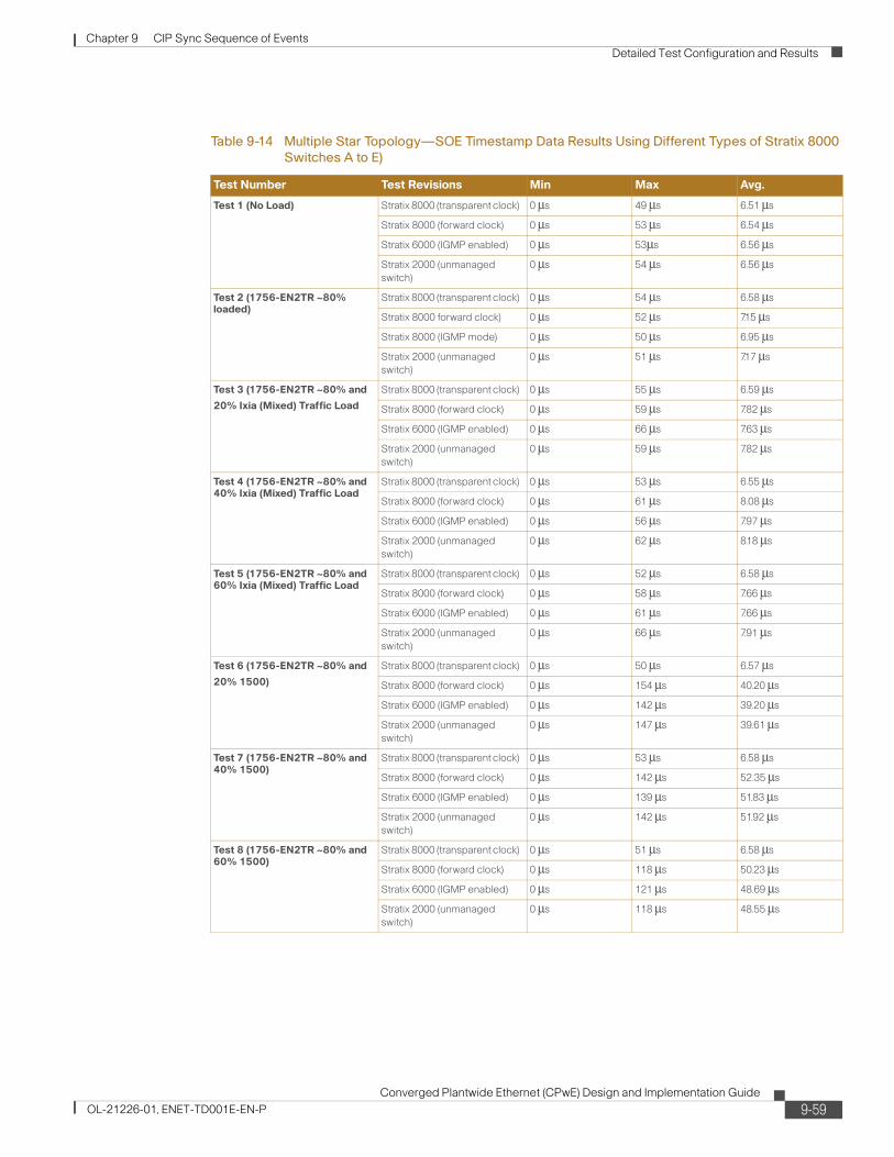
Table 9-8 Star Topology—SOE Timestamp Data Results Using Different Types of Stratix Switches (A to F)
Test Number Test Revisions Min Max Avg.
9-44Converged Plantwide Ethernet (CPwE) Design and Implementation Guide
OL-21226-01, ENET-TD001E-EN-P
Chapter 9 CIP Sync Sequence of Events
Detailed Test Configuration and Results
Architecture 2—Linear Topology (Using Devices With Embedded Dual-Port Ethernet Technology)
In the linear topology shown in Figure 9-37, all devices are connected in a daisy-chain fashion via the embedded dual Ethernet switch ports of each device. This embedded switch is a managed switch configured in transparent clock with QoS and IGMP enabled. Ixia traffic flows into the 1756-EN2TR module Ethernet port in local chassis 1 through the entire network and exits out the 1783- ETAP module 1 Ethernet port.
Figure 9-37 Linear Topology Using Embedded Dual-Port Ethernet Switch Devices with Transparent Clock
Architecture 3—Ring Topology (Device Level Ring Technology)
In the ring topology shown in Figure 9-38, all devices are connected in a device level ring via the embedded dual Ethernet switch ports of each device. This embedded switch is a managed switch configured in transparent Clock with QoS and IGMP enabled. Ixia traffic flows into the 1756-EN2TR module 1 Ethernet port in local chassis 1 through half of the network and exits out the 1783-ETAP module 4 Ethernet port.
2916
20
EN2TR
L6X
SOE
DOUT
EN2TR
SOE L
6X
1732E-IB16M12SOEDR
Armor Block I/O #3(F)
1732E-IB16M12SOEDR
Armor Block I/O #1(D)
1783-ETAP #21783-ETAP #1
S
1732E-IB16M12SOEDR
Armor Block I/O #2(E)
SS
EN2TR
SOE L
6X
IXIA PC 1OUT
IXIA PC 1IN
PanelViewPlus
ProgrammingTerminal
SS
ControlLogixLocal Chassis #1
(A)
ControlLogixRemote Chassis #2
(B)
ControlLogixRemote Chassis #3
(C)
SGM
M
M MS S S S S
9-45Converged Plantwide Ethernet (CPwE) Design and Implementation Guide
OL-21226-01, ENET-TD001E-EN-P
Chapter 9 CIP Sync Sequence of Events
Detailed Test Configuration and Results
Figure 9-38 Ring Topology Using Embedded Dual-Port Ethernet Switch Devices with Transparent Clock.
Tests 1 Through 8
The results of the following tests are described:
• Test 1—Test @ nominal traffic load (no traffic loading)
• Test 3—Test @ 1756-EN2TR loading ~80 percent and 20 percent Ixia (mixed) traffic load
• Test 4—Test @ 1756-EN2TR loading ~80 percent and 40 percent Ixia (mixed) traffic load
• Test 5—Test @ 1756-EN2TR loading ~80 percent and 60 percent Ixia (mixed) traffic load
• Test 6—Test @ 1756-EN2TR loading ~80 percent and 20 percent Ixia (1500-byte) traffic load
• Test 7—Test @ 1756-EN2TR loading ~80 percent and 40 percent Ixia (1500-byte) traffic load
• Test 8—Test @ 1756-EN2TR loading ~80 percent and 60 percent Ixia (1500-byte) traffic load
Note The SOE timestamping data chart shown in the following pages has data collected with the individual devices’ embedded dual-port Ethernet switch configured for transparent clock.
2916
21
EN2TR
L6X
SOE
DOUT
EN2TR
SOE L
6X
1732E-IB16M12SOEDR
Armor Block I/O #3(F)
1732E-IB16M12SOEDR
Armor Block I/O #1(D)
1783ETAP #2
1783ETAP #1
1783ETAP #3
1783ETAP #4
S
1732E-IB16M12SOEDR
Armor Block I/O #2(E)
SS
EN2TR
SOE L
6X
IXIA PC 1IN
PanelViewPlus
ProgrammingTerminal
IXIA PC 1OUT
T
SS
ControlLogixLocal Chassis #1
(A)
ControlLogixRemote Chassis #2
(B)
ControlLogixRemote Chassis #3
(C)
SGM
M
M MS S S S S
9-46Converged Plantwide Ethernet (CPwE) Design and Implementation Guide
OL-21226-01, ENET-TD001E-EN-P
Chapter 9 CIP Sync Sequence of Events
Detailed Test Configuration and Results
Figure 9-39 Linear Topology—SOE Timestamp Test 1 Results Using Embedded Dual-Port Ethernet Switch Devices with Transparent Clock (A to C)
Table 9-9 Linear Topology—SOE Timestamp Data Results Using the Embedded Dual-Port Ethernet Switch (A to C)
Test Number Test Revisions Min Max Avg.
Test 1 (No Load) Architecture 2 (Linear Topology)
Architecture 3 (Ring Topology)
0 μs
0 μs
65 μs
66 μs
8.45 μs
8.48 μs
Test 2 (1756-EN2TR ~80% Loaded) Architecture 2 (Linear Topology)
Architecture 3 (Ring Topology)
0 μs
0 μs
60 μs
59 μs
8.45 μs
8.49 μs
Test 3 (1756- EN2TR ~80% and 20% Mixed) Architecture 2 (Linear Topology)
Architecture 3 (Ring Topology)
0 μs
0 μs
65 μs
64 μs
8.42 μs
8.47 μs
Test 4 (1756- EN2TR ~80% and 40% Mixed) Architecture 2 (Linear Topology)
Architecture 3 (Ring Topology)
0 μs
0 μs
63 μs
65 μs
8.45 μs
8.48 μs
Test 5 (1756- EN2TR ~80% and 60% Mixed) Architecture 2 (Linear Topology)
Architecture 3 (Ring Topology)
0 μs
0 μs
58 μs
60 μs
8.45 μs
8.49 μs
Test 6 (1756- EN2TR ~80% and 20% 1500) Architecture 2 (Linear Topology)
Architecture 3 (Ring Topology)
0 μs
0 μs
62 μs
62 μs
8.48 μs
8.43 μs
Test 7 (1756- EN2TR ~80% and 40% 1500) Architecture 2 (Linear Topology)
Architecture 3 (Ring Topology)
0 μs
0 μs
65 μs
63 μs
8.50μs
8.48 μs
Test 8 (1756- EN2TR ~80% and 60% 1500) Architecture 2 (Linear Topology)
Architecture 3 (Ring Topology)
0 μs
0 μs
61μs
63 μs
8.46 μs
8.48 μs
9-47Converged Plantwide Ethernet (CPwE) Design and Implementation Guide
OL-21226-01, ENET-TD001E-EN-P
Chapter 9 CIP Sync Sequence of Events
Detailed Test Configuration and Results
Figure 9-40 Linear Topology—SOE Timestamp Test 1 Results Using Embedded Dual-Port Ethernet Switch Devices with Transparent Clock (A to D)
Table 9-10 Linear Topology—SOE Timestamp Data Results Using the Embedded Dual-Port Ethernet Switch (A to D)
Test Number Test Revisions Min Max Avg.
Test 1 (No Load) Architecture 2 (Linear Topology)
Architecture 3 (Ring Topology)
0 μs
0 μs
51 μs
51 μs
6.59 μs
6.59 μs
Test 2 (1756-EN2TR ~80% Loaded) Architecture 2 (Linear Topology)
Architecture 3 (Ring Topology)
0 μs
0 μs
48 μs
54 μs
6.57 μs
6.57 μs
Test 3 (1756- EN2TR ~80% and 20% Mixed) Architecture 2 (Linear Topology)
Architecture 3 (Ring Topology)
0 μs
0 μs
50 μs
51 μs
6.55 μs
6.57 μs
Test 4 (1756- EN2TR ~80% and 40% Mixed) Architecture 2 (Linear Topology)
Architecture 3 (Ring Topology)
0 μs
0 μs
50 μs
52 μs
6.60 μs
6.57 μs
Test 5 (1756- EN2TR ~80% and 60% Mixed) Architecture 2 (Linear Topology)
Architecture 3 (Ring Topology)
0 μs
0 μs
49 μs
52 μs
6.57 μs
6.60 μs
Test 6 (1756- EN2TR ~80% and 20% 1500) Architecture 2 (Linear Topology)
Architecture 3 (Ring Topology)
0 μs
0 μs
53μs
55 μs
6.59 μs
6.57 μs
Test 7 (1756- EN2TR ~80% and 40% 1500) Architecture 2 (Linear Topology)
Architecture 3 (Ring Topology)
0 μs
0 μs
53 μs
55 μs
6.59 μs
6.60 μs
Test 8 (1756- EN2TR ~80% and 60% 1500) Architecture 2 (Linear Topology)
Architecture 3 (Ring Topology)
0 μs
0 μs
54 μs
50 μs
6.57 μs
6.60 μs
9-48Converged Plantwide Ethernet (CPwE) Design and Implementation Guide
OL-21226-01, ENET-TD001E-EN-P
Chapter 9 CIP Sync Sequence of Events
Detailed Test Configuration and Results
Architecture 4—Multiple Star Topology (Separated Network Segments Using the 1756-EN2T Modules in Boundary Clock Mode)
In the multiple star topology shown in Figure 9-41, all devices are initially connected to a Stratix 8000 switch in a multiple star topology. The Stratix 8000 switch was tested in two PTP modes: transparent and forward clock with QoS and IGMP enabled. Subsequent testing was conducted using the Stratix 6000 switch with IGMP enabled, as well as the Stratix 2000 unmanaged switch. Ixia traffic flows into the 1756-EN2TR module 1 Ethernet port in local chassis 1 and exits out the 1732E-IB16M12SOEDR module 1 Ethernet port.
Figure 9-41 Multiple Star Topology Segmented by 1756-EN2T Modules with Boundary Clock and Stratix 8000 Switch with Transparent Clock
Note The SOE timestamping data chart shown in the following pages has data collected with a Stratix 8000 configured for transparent clock.
2916
22
Stratix8000
#1
Stratix8000#2
Stratix8000
#3
BoundaryClock #1
1732E-IB16M12SOEDR
Armor Block I/O #1(E)
S
IXIA PC 1OUT
IXIA PC 1IN
PanelViewPlus
ControlLogixLocal Chassis #1
(A)
ControlLogixRemote Chassis #2
(B)
Segment 1
Segment 2
Segment 3ControlLogix
Remote Chassis #3(C)
ControlLogixRemote Chassis #4
(D)
ProgrammingTerminal
EN2TR
L6X
SOE
DOUT
EN2TR
SOE L
6X
EN2T
EN2TR
SOE L
6X
EN2T
EN2TR
SOE L
6X
EN2T
PanelViewPlus
S M
BoundaryClock #2
S
S
M
1732E-IB16M12SOEDR
Armor Block I/O #2(F)
S
PanelViewPlus
1732E-IB16M12SOEDR
Armor Block I/O #3(G)
S
SGM
M
S
M S S S
M S S S
M S S S
9-49Converged Plantwide Ethernet (CPwE) Design and Implementation Guide
OL-21226-01, ENET-TD001E-EN-P
Chapter 9 CIP Sync Sequence of Events
Detailed Test Configuration and Results
Figure 9-42 Multiple Star Topology—SOE Timestamp Test 1 Results Using 1756-EN2T Modules with Boundary Clock and Stratix 8000 Switch with Transparent Clock (A to B)
Figure 9-43 Multiple Star Topology—SOE Timestamp Test 3 Results Using 1756-EN2T Modules with Boundary Clock and Stratix 8000 Switch with Transparent Clock (A to B)
9-50Converged Plantwide Ethernet (CPwE) Design and Implementation Guide
OL-21226-01, ENET-TD001E-EN-P
Chapter 9 CIP Sync Sequence of Events
Detailed Test Configuration and Results
Figure 9-44 Multiple Star Topology—SOE Timestamp Test 6 Results using 1756-EN2T Modules with Boundary Clock and Stratix 8000 Switches with Forward Clock (A to B)
Table 9-11 Multiple Star Topology—SOE Timestamp Data Results Using Different Types of Stratix 8000 Switches (A to B)
Test Number Test Revisions Min Max Avg.
Test 1 (No Load) Stratix 8000 (transparent clock) 0 μs 55 μs 8.44 μs
9-51Converged Plantwide Ethernet (CPwE) Design and Implementation Guide
OL-21226-01, ENET-TD001E-EN-P
Chapter 9 CIP Sync Sequence of Events
Detailed Test Configuration and Results
Figure 9-45 Multiple Star Topology—SOE Timestamp Test 1 Results Using 1756-EN2T Modules with Boundary Clock and Stratix 8000 Switch with Transparent Clock (A to C)
Test 5 (1756-EN2TR ~80% and 60% Ixia (Mixed) Traffic Load
Table 9-11 Multiple Star Topology—SOE Timestamp Data Results Using Different Types of Stratix 8000 Switches (A to B)
Test Number Test Revisions Min Max Avg.
9-52Converged Plantwide Ethernet (CPwE) Design and Implementation Guide
OL-21226-01, ENET-TD001E-EN-P
Chapter 9 CIP Sync Sequence of Events
Detailed Test Configuration and Results
Figure 9-46 Multiple Star Topology—SOE Timestamp Test 3 Results using EN2T Modules with Boundary Clock and Stratix 8000 Switch with Transparent Clock (A to C)
Figure 9-47 Multiple Star Topology—SOE Timestamp Test 6 Results using 1756-EN2T Modules with Boundary Clock and Stratix 8000 Switches with Forward Clock (A to C)
9-53Converged Plantwide Ethernet (CPwE) Design and Implementation Guide
OL-21226-01, ENET-TD001E-EN-P
Chapter 9 CIP Sync Sequence of Events
Detailed Test Configuration and Results
Table 9-12 Multiple Star Topology—SOE Timestamp Data Results Using Different Types of Stratix 8000 Switches (A to C)
Test Number Test Revisions Min Max Avg.
Test 1 (No Load) Stratix 8000 (transparent clock) 0 μs 61μs 8.42 μs
9-54Converged Plantwide Ethernet (CPwE) Design and Implementation Guide
OL-21226-01, ENET-TD001E-EN-P
Chapter 9 CIP Sync Sequence of Events
Detailed Test Configuration and Results
Figure 9-48 Multiple Star Topology—SOE Timestamp Test 1 Results Using 1756-EN2T Modules with Boundary Clock and Stratix 8000 Switch with Transparent Clock (A to D)
Figure 9-49 Multiple Star Topology—SOE Timestamp Test 3 Results using EN2T Modules with Boundary Clock and Stratix 8000 Switch with Transparent Clock (A to D)
9-55Converged Plantwide Ethernet (CPwE) Design and Implementation Guide
OL-21226-01, ENET-TD001E-EN-P
Chapter 9 CIP Sync Sequence of Events
Detailed Test Configuration and Results
Figure 9-50 Multiple Star Topology—SOE Timestamp Test 6 Results using 1756-EN2T Modules with Boundary Clock and Stratix 8000 Switches with Forward Clock (A to D)
Table 9-13 Multiple Star Topology—SOE Timestamp Data Results Using Different Types of Stratix 8000 Switches (A to D)
Test Number Test Revisions Min Max Avg.
Test 1 (No Load) Stratix 8000 (transparent clock) 0 μs 63 μs 8.59 μs
9-56Converged Plantwide Ethernet (CPwE) Design and Implementation Guide
OL-21226-01, ENET-TD001E-EN-P
Chapter 9 CIP Sync Sequence of Events
Detailed Test Configuration and Results
Figure 9-51 Multiple Star Topology—SOE Timestamp Test 1 Results Using 1756-EN2T Modules with Boundary Clock and Stratix 8000 Switch with Transparent Clock (A to E)
Test 5 (1756-EN2TR ~80% and 60% Ixia (Mixed) Traffic Load
Table 9-13 Multiple Star Topology—SOE Timestamp Data Results Using Different Types of Stratix 8000 Switches (A to D)
Test Number Test Revisions Min Max Avg.
9-57Converged Plantwide Ethernet (CPwE) Design and Implementation Guide
OL-21226-01, ENET-TD001E-EN-P
Chapter 9 CIP Sync Sequence of Events
Detailed Test Configuration and Results
Figure 9-52 Multiple Star Topology—SOE Timestamp Test 3 Results using 1756-EN2T Modules with Boundary Clock and Stratix 8000 Switch with Transparent Clock (A to E)
Figure 9-53 Multiple Star Topology—SOE Timestamp Test 6 Results using 1756-EN2T Modules with Boundary Clock and Stratix 8000 Switches with Forward Clock (A to E)
9-58Converged Plantwide Ethernet (CPwE) Design and Implementation Guide
OL-21226-01, ENET-TD001E-EN-P
Chapter 9 CIP Sync Sequence of Events
Detailed Test Configuration and Results
Table 9-14 Multiple Star Topology—SOE Timestamp Data Results Using Different Types of Stratix 8000 Switches A to E)
Test Number Test Revisions Min Max Avg.
Test 1 (No Load) Stratix 8000 (transparent clock) 0 μs 49 μs 6.51 μs
9-59Converged Plantwide Ethernet (CPwE) Design and Implementation Guide
OL-21226-01, ENET-TD001E-EN-P
Chapter 9 CIP Sync Sequence of Events
Detailed Test Configuration and Results
Figure 9-54 Multiple Star Topology—SOE Timestamp Test 1 Results Using 1756-EN2T Modules with Boundary Clock and Stratix 8000 Switch with Transparent Clock (A to F)
Figure 9-55 Multiple Star Topology—SOE Timestamp Test 3 Results using EN2T Modules with Boundary Clock and Stratix 8000 Switch with Transparent Clock (A to F)
9-60Converged Plantwide Ethernet (CPwE) Design and Implementation Guide
OL-21226-01, ENET-TD001E-EN-P
Chapter 9 CIP Sync Sequence of Events
Detailed Test Configuration and Results
Figure 9-56 Multiple Star Topology—SOE Timestamp Test 6 Results using 1756-EN2T Modules with Boundary Clock and Stratix 8000 Switches with Forward Clock (A to F)
Table 9-15 Multiple Star Topology—SOE Timestamp Data Results Using Different Types of Stratix 8000 Switches (A to F)
Test Number Test Revisions Min Max Avg.
Test 1 (No Load) Stratix 8000 (transparent clock) 0 μs 49 μs 6.51 μs
9-61Converged Plantwide Ethernet (CPwE) Design and Implementation Guide
OL-21226-01, ENET-TD001E-EN-P
Chapter 9 CIP Sync Sequence of Events
Detailed Test Configuration and Results
Figure 9-57 Multiple Star Topology—SOE Timestamp Test 1 Results Using 1756-EN2T Modules with Boundary Clock and Stratix 8000 Switch with Transparent Clock (A to G)
Test 5 (1756-EN2TR ~80% and 60% Ixia (Mixed) Traffic Load
Table 9-15 Multiple Star Topology—SOE Timestamp Data Results Using Different Types of Stratix 8000 Switches (A to F)
Test Number Test Revisions Min Max Avg.
9-62Converged Plantwide Ethernet (CPwE) Design and Implementation Guide
OL-21226-01, ENET-TD001E-EN-P
Chapter 9 CIP Sync Sequence of Events
Detailed Test Configuration and Results
Figure 9-58 Multiple Star Topology—SOE Timestamp Test 3 Results using EN2T Modules with Boundary Clock and Stratix 8000 Switch with Transparent Clock (A to G)
Figure 9-59 Multiple Star Topology—SOE Timestamp Test 6 Results using 1756-EN2T Modules with Boundary Clock and Stratix 8000 Switches with Forward Clock (A to G)
9-63Converged Plantwide Ethernet (CPwE) Design and Implementation Guide
OL-21226-01, ENET-TD001E-EN-P
Chapter 9 CIP Sync Sequence of Events
Detailed Test Configuration and Results
Table 9-16 Multiple Star Topology—SOE Timestamp Data Results Using Different Types of Stratix 8000 Switches (A to G)
Test Number Test Revisions Min Max Avg.
Test 1 (No Load) Stratix 8000 (transparent clock) 0 μs 47 μs 6.58 μs
9-64Converged Plantwide Ethernet (CPwE) Design and Implementation Guide
OL-21226-01, ENET-TD001E-EN-P
Chapter 9 CIP Sync Sequence of Events
Detailed Test Configuration and Results
Architecture 5—Star Topology (Propagating PTP Packets across Different VLANs Using the Stratix 8300 in Boundary Clock Mode)
As shown in Figure 9-60, all devices are connected to a Stratix 8000 switch in a star topology. The Stratix 8000 switch was tested in three PTP modes: transparent, boundary, and forward clock with QoS and IGMP enabled. Ixia traffic flows into the 1756-EN2TR module Ethernet port in local chassis 1 and exits out the 1732E-IB16M12SOEDR module 1 Ethernet port.
Figure 9-60 Star Topology Segmented with VLANs Using the Stratix 8300 Switch with Boundary Clock and the Stratix 8000 Switch with Forward Clock
The test configuration seen in Figure 9-60 could not be conducted because the 1756-IB16ISOE module does not support a unicast connection at this time. This has been illustrated with a red X over the remote 1756-IB16ISOE modules. Instead, a simpler test was conducted with the local 1756-IB16ISOE and remote 1756-IB32SOE modules. This test was successful.
Note The SOE timestamping data chart shown in the following pages has data collected with a Stratix 8000 switch configured for transparent clock.
291624
Stratix8300(BM)
Stratix8000
#2
Stratix8000
#3
VLAN 20
VLAN 30VLAN 10
PanelViewPlus
EN2TR
SOE L
6X
EN2TR
L6X
SOE
DOUT
EN2TR
SOE L
6X
Stratix8000
#1
1732E-IB16M12SOEDR
Armor Block I/O #1(D)
S
1732E-IB16M12SOEDR
Armor Block I/O #2(F)
S
S
S
IXIA PC 1OUT
IXIA PC 1IN
PanelViewPlus
ProgrammingTerminal
M
M
PanelViewPlus
1732E-IB16M12SOEDR
Armor Block I/O #3(G)
S
S
ControlLogixLocal Chassis #1
(A)
SGM
M
S
S
ControlLogixRemote Chassis #2
(B)
M S S
S
ControlLogixRemote Chassis #3
(C)
M S S
9-65Converged Plantwide Ethernet (CPwE) Design and Implementation Guide
OL-21226-01, ENET-TD001E-EN-P
Chapter 9 CIP Sync Sequence of Events
Detailed Test Configuration and Results
Figure 9-61 Star Topology—SOE Timestamp Test 1 Results using the Stratix 8300 with Boundary Clock and the Stratix 8000 Switch with Transparent Clock (A to D)
Figure 9-62 Star Topology—SOE Timestamp Test 3 Results Using the Stratix 8300 Switch with Boundary Clock and the Stratix 8000 Switch with Transparent Clock (A to D)
9-66Converged Plantwide Ethernet (CPwE) Design and Implementation Guide
OL-21226-01, ENET-TD001E-EN-P
Chapter 9 CIP Sync Sequence of Events
Detailed Test Configuration and Results
Figure 9-63 Star Topology—SOE Timestamp Test 6 Results Using the Stratix 8300 Switch with Boundary Clock and the Stratix 8000 Switch with Forward Clock (A to D)
Table 9-17 Star Topology—SOE Timestamp Data Results Using the Stratix 8000 Switch (A to D)
Test Number Test Revisions Min Max Avg.
Test 1 (No Load) Stratix 8000 (transparent clock) 0 μs 56 μs 6.50 μs
9-67Converged Plantwide Ethernet (CPwE) Design and Implementation Guide
OL-21226-01, ENET-TD001E-EN-P
Chapter 9 CIP Sync Sequence of Events
Detailed Test Configuration and Results
Figure 9-64 Star Topology—SOE Timestamp Test 1 Results using the Stratix 8300 with Boundary Clock and the Stratix 8000 Switch with Transparent Clock (A to E)
Figure 9-65 Star Topology—SOE Timestamp Test 3 Results Using the Stratix 8300 Switch with Boundary Clock and the Stratix 8000 Switch with Transparent Clock (A to E)
Table 9-17 Star Topology—SOE Timestamp Data Results Using the Stratix 8000 Switch (A to D)
Test Number Test Revisions Min Max Avg.
9-68Converged Plantwide Ethernet (CPwE) Design and Implementation Guide
OL-21226-01, ENET-TD001E-EN-P
Chapter 9 CIP Sync Sequence of Events
Detailed Test Configuration and Results
Figure 9-66 Star Topology—SOE Timestamp Test 6 Results Using the Stratix 8300 Switch with Boundary Clock and the Stratix 8000 Switch with Forward Clock (A to E)
Table 9-18 Star Topology—SOE Timestamp Data Results Using the Stratix 8000 Switch (A to E)
Test Number Test Revisions Min Max Avg.
Test 1 (No Load) Stratix 8000 (transparent clock) 0 μs 57 μs 6.41 μs
9-69Converged Plantwide Ethernet (CPwE) Design and Implementation Guide
OL-21226-01, ENET-TD001E-EN-P
Chapter 9 CIP Sync Sequence of Events
Detailed Test Configuration and Results
Figure 9-67 Star Topology—SOE Timestamp Test 1 Results using the Stratix 8300 with Boundary Clock and the Stratix 8000 Switch with Transparent Clock (A to F)
Figure 9-68 Star Topology—SOE Timestamp Test 3 Results Using the Stratix 8300 Switch with Boundary Clock and the Stratix 8000 Switch with Transparent Clock (A to F)
9-70Converged Plantwide Ethernet (CPwE) Design and Implementation Guide
OL-21226-01, ENET-TD001E-EN-P
Chapter 9 CIP Sync Sequence of Events
Detailed Test Configuration and Results
Figure 9-69 Star Topology—SOE Timestamp Test 6 Results Using the Stratix 8300 Switch as Boundary Clock and the Stratix 8000 Switch as Forward Clock (A to F)
Table 9-19 Star Topology—SOE Timestamp Data Results Using the Stratix 8000 Switch (A to F)
Test Number Test Revisions Min Max Avg.
Test 1 (No Load) Stratix 8000 (transparent clock) 0 μs 56 μs 6.62 μs