57
CADlink Technology Corporation © February 2010 Digital Factory 2 Demo
CADlink Technology Corporation© February 2010
Digital Factory 2
Demo

2 Digital Factory 2 Demo

3Table of Contents
Table of ConTenTsCopyright Notice .........................................................................5Contact Information ...................................................................7
Welcome to Digital Factory 9Digital Factory Highlights ........................................................10
Printing ............................................................................... 10Print and Cut ..................................................................... 12Job Management ............................................................... 16Layout Controls ................................................................ 20Media Support .................................................................. 24
Installing Digital Factory 28Step 1 - Program Installation ...................................................28Step 2 - Printer Installation ......................................................29Step 3 - Cutter Installation .......................................................31Step 4 - Queue Creation ...........................................................32
Sending Jobs to Digital Factory 33Sending Jobs from SignLab® ..................................................34Sending Jobs from PhotoShop® ............................................36
Creating Paths in PhotoShop ......................................... 38Sending Jobs from Illustrator® ...............................................38Sending Jobs from CorelDraw® .............................................40Sending Jobs from Other Design Applications ....................42Importing Designs Directly into Digital Factory .................47Sending Jobs Across a Network ..............................................49Sending Jobs from Non-Windows Computers .....................53
Additional Information 57

4 Digital Factory 2 Demo

5Copyright Notice
CopyrighT noTiCeNo part of this publication may be reproduced mechanically or electronically or in any form without the prior written permission of CADlink. The software described in this manual is furnished under license and may only be used or copied in accordance with the terms of such license. The information in this manual is for informational use only, is subject to change without notice and should not be construed as a commitment by CADlink. CADlink assumes no responsibility or liability for any errors or inaccuracies that may appear in this document. Digital Factory®, Visual Print Manager®, Visual Production Manager® and SignLab® are registered trademarks of CADlink Technology Corporation.
Written and designed at CADlink Technology Corporation
2440 Don Reid Drive, Ottawa, ON, Canada, K1H 1E1
Phone (613) 247-0850 Fax (613) 247-1488
Manual & Package Design by CADlink Marketing and Customer Support.
Printed in Canada. Product of Canada.
© February 2010, CADlink Technology Corporation

6 Digital Factory 2 Demo

7Contact Information
ConTaCT informaTionContact CADlink Sales for advice about further Digital Factory (and related) features that pertain to your shop production.
Internet
www.cadlink.com/digitalFactory
UnIted StateS
500 Main Street
Clinton, MA 01510
Tel: 1-800-545-9581
Fax: (613) 247-1488
Canada
2440 Don Reid Drive
Ottawa, ON K1H 1E1
Tel: (613) 247-0850
Fax: (613) 247-1488
eUrope
Intech House, Wilbury Way
Hitchin, Herts, U.K. SG4 0TW
Tel: ++44(0) 1462-420222
Fax: ++44(0) 1462-420111

8 Digital Factory 2 Demo

9Welcome to Digital Factory
WelCome To DigiTal faCToryDigital Factory is a production management tool that serves as a repository for all of your volume production printing and/or cutting activities. Sorting and accumulating jobs is accomplished by creating one-or-more queues for each of your machines, thereby providing a simple means for designers to output their designs.
From a designer perspective, a queue in Digital Factory appears as a print destination (i.e., in the application Print dialog), and designers are otherwise insulated from the technical aspects of production. However, for the operator that oversees production, they are presented with a clean interface that allows them to preview jobs at a glance (Fig. 1), and intuitive controls that can be set behind-the-scenes.
Fig. 1 - The Digital Factory window. On the left, one-or-more queues organize your jobs for a particular machine or type of media. On the right, the Visual Print Manager shows jobs as they will appear on the media.

10 Digital Factory 2 Demo
DigiTal faCTory highlighTs
For both new and experienced users, the following sections highlight key features and functionality of Digital Factory:
□ Printing
□ Print and Cut
□ Job Management
□ Layout Tools
□ Media Support
Printing
□ RIP Engine – Digital Factory is a high quality Raster Image Processor (RIP) solution that provides PostScript Level 3 compatible printing for Large Format Printers (LFP) and Desktop Printers (DTP).
□ Direct Printing From Your Design Application – Digital Factory is a seamless interface that can be configured to run in the background and serve as a File menu >> Print destination for your designers.
□ Remote Printing Across Networks – In cases where your designers are elsewhere on the Windows network, or even using other operating systems like Mac OSX or Linux, extra optional functionality using Hot Folders can be used to print despite network or hardware limitations (Fig. 2).

11Digital Factory Highlights
Fig. 2 - Design work can be performed using your preferred design package with support for Macintosh and Linux-based systems as well. Digital Factory acts as a print destination and repository for print and/or cut jobs.
12 Digital Factory 2 Demo
Print and Cut
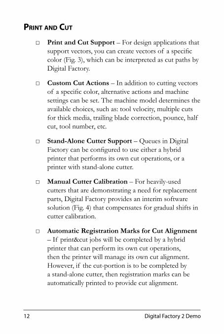
□ Print and Cut Support – For design applications that support vectors, you can create vectors of a specific color (Fig. 3), which can be interpreted as cut paths by Digital Factory.
□ Custom Cut Actions – In addition to cutting vectors of a specific color, alternative actions and machine settings can be set. The machine model determines the available choices, such as: tool velocity, multiple cuts for thick media, trailing blade correction, pounce, half cut, tool number, etc.
□ Stand-Alone Cutter Support – Queues in Digital Factory can be configured to use either a hybrid printer that performs its own cut operations, or a printer with stand-alone cutter.
□ Manual Cutter Calibration – For heavily-used cutters that are demonstrating a need for replacement parts, Digital Factory provides an interim software solution (Fig. 4) that compensates for gradual shifts in cutter calibration.
□ Automatic Registration Marks for Cut Alignment – If print&cut jobs will be completed by a hybrid printer that can perform its own cut operations, then the printer will manage its own cut alignment. However, if the cut-portion is to be completed by a stand-alone cutter, then registration marks can be automatically printed to provide cut alignment.

13Digital Factory Highlights
Fig. 4 - Compensate for gradual shifts in cutter resolution.
Fig. 3 - Interpret strokes as cut paths or alternative actions.

14 Digital Factory 2 Demo
□ Spot White Background for Registration Marks – For off-white and clear transparent media, print a spot white background for registration marks (Fig. 5), thereby enabling cutters with optical eye systems to automatically align to the marks. This feature requires a printer that is capable of printing spot white.
□ Printed Barcodes to Locate Cut Jobs – Digital Factory supports hybrid printers that can read barcodes to locate the cut portion of print&cut jobs. Alternatively, Digital Factory provides a manual method of either scanning the barcode with a handheld reader, or typing the printed identification number.
□ Sort Cut Jobs – Reduce cutting time by specifying the most efficient order in which cut paths should be performed.
□ Weed Borders – A weed border is an additional rectangular (Fig. 6) cut around the primary shape (i.e., small script lettering), which is used to avoid stretched media when separating shapes from their adhesive backing.
□ Cut from End of Roll – For print&cut jobs that use a stand-alone cutter, designate that the entire roll will be printed, and that the printed roll will then be fed into the cutter without rewinding the roll (Fig. 7). Digital Factory will process the cut jobs in reverse order, thereby avoiding the need to rewind the roll.

15Digital Factory Highlights
Fig. 6 - Cut weed borders to avoid stretched media around delicate artwork.
Fig. 5 - Print spot white to aid optical alignment systems.
Fig. 7 - Load printed rolls into the cutter without needing to rewind the media.

16 Digital Factory 2 Demo
Job ManageMent
□ Queue Organization – One-or-more queues can organize your jobs for each machine and for different types of media (Fig. 8). By accumulating jobs in each queue, they can be held until the required media and inks are loaded into the machine.
□ At-a-Glance Queue Switching – Each queue is organized as a tab for convenient switching (Fig. 9). Merely click to see the jobs that have been accumulated, or double-click to check the properties of the given queue.
□ File Import – Design files can be imported directly into Digital Factory, where they will become a job in the currently active queue. Importing a previously completed design file avoids the need to pre-load the file in the original design application.
□ Inherited Queue Properties – When jobs are received in a given queue, they inherit the properties of that queue, thereby removing concern from the designer about what settings need to be used for the given media and inks.
□ Job Scheduling – Choose how jobs should proceed based upon the type of job. For example, if print jobs are being held, then rasterize the job while waiting. Or for print-laminate-cut jobs, hold the cut portion until after the printed media has been laminated.

17Digital Factory Highlights
Fig. 8 - Accumulate jobs until the appropriate media and inks are loaded.
Fig. 9 - Click a tab to access its queue, or double-click for queue properties.

18 Digital Factory 2 Demo
□ Job Archiving – After a job has been completed, the job file can be saved for sending the job additional times without needing to re-send the file from the design application. Likewise, if the spool file has been archived, then the job can be resent without spending time rasterizing the job.
□ Job Costing – Ink usage data can be collected (Fig. 10) to predict the production costs associated with the completing similar print runs. As more data is collected, an average trend in ink usage should be apparent, thereby providing greater ability to predict anticipated material needs for upcoming jobs.
□ Crop Mark Annotations – In addition to marking the bounds of the print job, crop marks can now include job details (Fig. 11), such as job name, cutter name, job size, etc.

19Digital Factory Highlights
Fig. 10 - Optionally, job costing can be calculated down to the picoliters of ink being applied, though you will need specification data for the given printer.
Fig. 11 - When creating crop marks, include reminders about the job specifications.

20 Digital Factory 2 Demo
Layout ControLs
□ Visual Print Manager – As part of the Digital Factory interface, the Visual Print Manager (Fig. 12) previews jobs as they will appear on the media. Use this functionality to confirm spacing between jobs, positioning of jobs, usage of media, etc., with easy scrolling and zooming to inspect the media.
□ Tiling and Cropping – Visually divide (Fig. 13) a large job into tiles by either specifying tile dimensions or dragging tile lines for careful positioning. Overlap and margin amounts are automatically taken into account.
□ Copies – When copies are created within Digital Factory, only the original design will be rasterized, and the job copies will reuse the rasterization data (Fig. 14). In comparison, if multiple copies of a job are sent from the design application, then all such copies will be rasterized individually (i.e., more processing time would be required).
□ Template Media Layouts – Create custom page layouts that will automatically place jobs at specific positions upon the media (Fig. 15). Templates can automatically scale, rotate, and create copies. Copies can be scaled and rotated on an individual copy basis.
□ Automatic Nesting – Collect and reposition jobs to conserve media (Fig. 16), and then begin printing when there are enough jobs to fill an entire sheet or roll. Alternatively, specify that printing should begin when a certain proportion of the media can be filled.

21Digital Factory Highlights
Fig. 12 - The Visual Print Manager previews jobs as they appear on the media.
Fig. 13 - Tile a job when it exceeds the media bounds, or crop the design.

22 Digital Factory 2 Demo
Fig. 14 - When making copies in Digital Factory, print data will only be calculated for the original, and processing time will be avoided by reusing the original print data.

23Digital Factory Highlights
Fig. 16 - Automatic nesting will collect and reposition jobs to conserve media.
Fig. 15 - Template layouts will automatically create and position copies, including any scaling or rotating.

24 Digital Factory 2 Demo
Media suPPort
□ Online Printer Support File Updates – Digital Factory already comes equipped with a broad selection of media profiles, which are organized according to printer model, media, inks, print speed, and print quality. The latest support files can be quickly obtained through your Internet connection (Fig. 17).
□ Color and Image Adjustments – These adjustments to the color and image settings can compensate for non-standard media and inks (Fig. 18), where the cost of producing a new media profile is otherwise prohibitive.
□ Ink Volume Control – To improve the color saturation of your prints, use Max Ink adjustments (Fig. 19) to increase the volume of ink that is absorbed by the media. Like the color and image adjustments, the max ink settings can be used to compensate for slightly different absorbency of a substitute media.
□ Separation Curves – For printers that combine inks to obtain a wider range of hues (e.g., cyan in combination with light cyan), the separation curves can be adjusted to maximize the possible range of hues (Fig. 20).
□ Custom Halftone Settings – Override the halftone settings (Fig. 21) to obtain the optimum frequency, angle and dot shape for high quality jobs.
□ Preview Raw Print Data – Inspect print data on-screen prior to printing (Fig. 22), so that print data can be confirmed on a per color channel basis.

25Digital Factory Highlights
Fig. 17 - Use the Internet to automatically download the latest printer support files.
Fig. 18 - Color adjustments compensate for substituted media and inks.

26 Digital Factory 2 Demo
Fig. 19 - Adjust ink volume to improve color saturation in prints.
Fig. 20 - Combine light inks to maximize the dynamic range of printed hues.
Fig. 21 - Adjust halftone settings for consistent screen printing results.

27Digital Factory Highlights
Fig. 22 - Inspect raw print data before committing to print.
28 Digital Factory 2 Demo
insTalling DigiTal faCTory
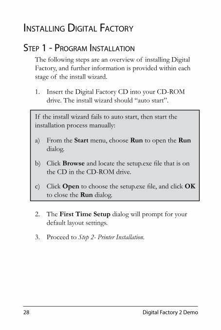
sTep 1 - program insTallaTionThe following steps are an overview of installing Digital Factory, and further information is provided within each stage of the install wizard.
1. Insert the Digital Factory CD into your CD-ROM drive. The install wizard should “auto start”.
If the install wizard fails to auto start, then start the installation process manually:
a) From the Start menu, choose Run to open the Run dialog.
b) Click Browse and locate the setup.exe file that is on the CD in the CD-ROM drive.
c) Click Open to choose the setup.exe file, and click OK to close the Run dialog.
2. The First Time Setup dialog will prompt for your default layout settings.
3. Proceed to Step 2- Printer Installation.

29Installing Digital Factory
sTep 2 - prinTer insTallaTion
1. Previously, the First Time Setup dialog was used to define your default layout settings.
2. Next, the Create Queue Wizard will launch (Introduction page), which will be used to install support files for your printer and/or cutter.At this time, it is recommended that you install your primary production printer into Digital Factory. Later, it will be possible to install additional printers.
3. If your Digital Factory package includes a Printers DVD, then insert the DVD into your DVD-ROM drive.
4. From the Introduction page, click Next.
5. From the Printer Defaults page (Fig. 23):
a) Click the Install Printer button, and follow the steps for choosing the printer model and installing its printer support files.
b) Once the support files have been installed, click the Port drop-list and indicate the computer port that the printer is connected to.
c) To the right of the Print Mode drop-list, click the ellipsis button.
d) From the Print Mode Selection dialog, use the drop-lists to refine the selection of print modes (i.e., media profiles), such that you can choose the

30 Digital Factory 2 Demo
most appropriate print mode for the loaded inks and media.
e) From the Printer Defaults page, click Next to proceed.
Fig. 23 - From the Printer Defaults page, install and configure your first printer. Later, more printers can be installed using Devices menu >> Manage Devices.

31Installing Digital Factory
sTep 3 - CuTTer insTallaTion
1. From the Cutter Defaults page (Fig. 24), click the Install Cutter button and follow the steps for choosing the cutter model and installing the cutter driver.For hybrid printers that can perform their own cutting, the printer name will be available as a Cutter drop-list option.
2. Once the cutter driver has been installed, click the Port drop-list and indicate the computer port that the cutter is connected to.
3. From the Cutter Defaults page, click Next.
Fig. 24 - From the Cutter Defaults page, install and configure your first cutter. As with printers, more cutters can be installed using Devices menu >> Manage Devices.

32 Digital Factory 2 Demo
sTep 4 - Queue CreaTionClick Next to proceed through each remaining step of the wizard.
1. The Name Your Production Queue page asks you to provide a meaningful name that this queue will be referred to.
2. The Media Setup page asks you to define the media size and margins.
3. The Registration Marks page asks for the alignment system that will be used. Refer to the cutter operation manual for an explanation of the available choices.If print&cut jobs will be completed by a hybrid printer that can perform its own cut operations, then the printer will manage its own cut alignment. However, if the cut-portion is to be completed by a stand-alone cutter, then registration marks are printed to provide cut alignment.
3. The Layout Mode page asks you to choose how jobs will be nested on the media.
4. The Output Options page is used to choose how jobs are held when received by Digital Factory.
5. When ready, click Finish to conclude the wizard, and Digital Factory will launch.
To test that your designs are being processed correctly, proceed to the next section, Sending Jobs to Digital Factory.

33Sending Jobs to Digital Factory
senDing Jobs To DigiTal faCToryOnce you have installed Digital Factory, each of the following workflows is designed to help you confirm that print and/or cut jobs are being received and processed by Digital Factory correctly. Choose the workflow that best represents the method by which you will use Digital Factory.
Sending Jobs on Same ComputerFor these workflows, your design application and Digital Factory have been installed to the same computer.
□ Sending Jobs from SignLab
□ Sending Jobs from PhotoShop
□ Sending Jobs from Illustrator
□ Sending Jobs from CorelDraw
□ Sending Jobs from Other Design Applications
Sending Jobs from Separate ComputersFor these workflows, your design application and Digital Factory have been installed on separate computers.
□ Importing Designs Directly into Digital Factory
□ Sending Jobs Across a Network
□ Sending Jobs from Non-Windows Computers

34 Digital Factory 2 Demo
Print&Cut
senDing Jobs from signlab®In the following procedure, the gray boxes represent steps that are necessary in order to include cut paths with your print job (i.e., to create a print&cut job). If you wish to complete a print-only job, then skip the steps in gray.
In Digital Factory
1. From the toolbar, click the Start Queue button.
2. Choose Queue menu >> Manage Queues.
3. In the Control Panel column, click the Install button, such that the queue is available as a print destination for other Windows applications.
4. Click the Close button.
5. In Digital Factory, go Queue menu >> Properties >> Color Actions tab.
6. Click Add Color to define a specific vector color (CMYK or named) that Digital Factory will recognize as a cut path.
7. Click OK to close the Queue Properties dialog.

35Sending Jobs to Digital Factory
Print&Cut
Print&Cut
In SignLab
8. Prepare the print design on the SignLab workspace.
9. Create a shape that will represent the cutting path.
10. For the cut path shape, assign an invisible fill, and create a hairline stroke that uses the color set in step (6).
11. Save the design file, such that the design is not “untitled.”
12. Choose File menu >> Print to open the Print dialog.
13. From the Printer tab, choose the queue that had been designated in step (3).
14. Click OK to accept the Print dialog settings, and the job will be received in Digital Factory.
In Digital Factory
15. In the Active List, the job thumbnail will have a knife icon to indicate that cut data has been located.
16. To see the cut paths in the Visual Print Manager, choose Show Print and Cut Previews from the drop-list.
17. If your queue is set to hold received jobs, then select the job and choose to either print, cut or print&cut from the Jobs menu.

36 Digital Factory 2 Demo
Print&Cut
senDing Jobs from phoToshop®In the following procedure, the gray boxes represent steps that are necessary in order to include cut paths with your print job (i.e., to create a print&cut job). If you wish to complete a print-only job, then skip the steps in gray.
In Digital Factory
1. From the toolbar, click the Start Queue button.
In PhotoShop
2. Prepare the print design in PhotoShop.
3. Create a path that will represent the cutting path (See Creating Paths in PhotoShop).
4. Save the PSD file, such that the design is not “untitled.”
5. Choose File menu >> Automate >> Send to VPM.
6. In the Send to VPM dialog, choose the queue name and click OK.
7. The job will be received in Digital Factory.
Alternatively, the PSD file (or an exported file in TIFF or JPEG format) will preserve the path information, which can then be loaded into Digital Factory via File menu >> Import File.

37Sending Jobs to Digital Factory
Print&Cut
Print&CutIn Digital Factory
8. The PhotoShop Document Path Import Options dialog will open.
9. Tick the Import working path as cut lines checkbox.
10. In the Cut Line Color section, choose the color that will identify the path within the imported file (i.e., the imported path will be converted into a “cut path” and assigned this color).
Note: For the path color, choose an unique color that will specifically represent paths to be cut from Digital Factory. All vectors that have this stroke color will be processed as cut paths.
11. Click OK to proceed with the import options.
12. (Optional) If the Image Import dialog is enabled, then clicking OK will proceed with the import.
13. In the Active List, the job thumbnail will have a knife icon to indicate that cut data is present.
14. To see the cut paths in the Visual Print Manager, choose Show Print and Cut Previews from the drop-list.
15. If your queue is set to hold received jobs, then select the job and choose to either print, cut or print&cut from the Jobs menu.

38 Digital Factory 2 Demo
Print&Cut
Creating Paths in PhotoshoP
The following are quick pointers for creating paths in PhotoShop:
□ To view paths within a PhotoShop file, inspect the Paths palette (Window menu >> Paths)
□ To draw paths from the Paths palette, click the Create new path button, and then use the Pen Tool (P). The Path Selection Tool (A) is used to select and move path nodes.
□ If shape tools (U) are being used, then click the Paths button. When shapes are drawn, paths will be created instead of filled pixels.
□ If the selection marquee would make a good path, then from the Paths palette click the Make work path from selection button.
senDing Jobs from illusTraTor®In the following procedure, the gray boxes represent steps that are necessary in order to include cut paths with your print job (i.e., to create a print&cut job). If you wish to complete a print-only job, then skip the steps in gray.
In Digital Factory
1. From the toolbar, click the Start Queue button.
2. Choose Queue menu >> Properties >> Color Actions tab.
3. Click Add Color to define a specific vector color (CMYK or named) that Digital Factory will recognize as a cut path.
4. Click OK to close the Queue Properties dialog.

39Sending Jobs to Digital Factory
Print&Cut
Print&Cut
In Illustrator
5. Prepare the print design in Illustrator.
6. Create a shape that will represent the cutting path.
7. For the cut path shape, assign an invisible fill, and create a hairline stroke that uses the color set in step (3).
8. Save the design file, such that the design is not “untitled.”
9. Choose File menu >> Send to VPM.
10. In the Send to VPM dialog, choose the queue name and click OK.
11. The job will be received in Digital Factory.
In Digital Factory
12. In the Active List, the job thumbnail will have a knife icon to indicate that cut data has been located.
13. To see the cut paths in the Visual Print Manager, choose Show Print and Cut Previews from the drop-list.
14. If your queue is set to hold received jobs, then select the job and choose to either print, cut or print&cut from the Jobs menu.

40 Digital Factory 2 Demo
Print&Cut
Print&Cut
senDing Jobs from CorelDraW®In the following procedure, the gray boxes represent steps that are necessary in order to include cut paths with your print job (i.e., to create a print&cut job). If you wish to complete a print-only job, then skip the steps in gray.
In Digital Factory
1. From the toolbar, click the Start Queue button.
2. Choose Queue menu >> Properties >> Color Actions tab.
3. Click Add Color to define a specific vector color (CMYK or named) that Digital Factory will recognize as a cut path.
4. Click OK to close the Queue Properties dialog.
In CorelDraw
5. Prepare the print design in CorelDraw.
6. Create a shape that will represent the cutting path.
7. For the cut path shape, assign its fill to None, and assign a hairline stroke that uses the color set in step (3).
8. Save the design file, such that the design is not “untitled.”
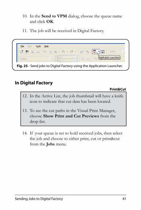
9. From the Application Launcher button (Fig. 25), choose Send to VPM.
41Sending Jobs to Digital Factory
Print&Cut
10. In the Send to VPM dialog, choose the queue name and click OK.
11. The job will be received in Digital Factory.
In Digital Factory
12. In the Active List, the job thumbnail will have a knife icon to indicate that cut data has been located.
13. To see the cut paths in the Visual Print Manager, choose Show Print and Cut Previews from the drop-list.
14. If your queue is set to hold received jobs, then select the job and choose to either print, cut or print&cut from the Jobs menu.
Fig. 25 - Send jobs to Digital Factory using the Application Launcher.

42 Digital Factory 2 Demo
Print&Cut
senDing Jobs from oTher Design appliCaTionsFor other design applications that were not covered in the previous sections, the File menu >> Print command can be used to send jobs to Digital Factory. However, please note that the design application must be capable of defining vectors, which will be converted into cut paths when received by Digital Factory.In the following procedure, the gray boxes represent steps that are necessary in order to include cut paths with your print job (i.e., to create a print&cut job). If you wish to complete a print-only job, then skip the steps in gray.
In Digital Factory
1. From the toolbar, click the Start Queue button.
2. Choose Queue menu >> Manage Queues.
3. In the Control Panel column, click the Install button, such that the queue is available as a print destination for other Windows applications.
4. Click the Close button.
5. Choose Queue menu >> Properties >> Color Actions tab.
6. Click Add Color to define a specific vector color (CMYK or named) that Digital Factory will recognize as a cut path.
7. Click OK to close the Queue Properties dialog.
43Sending Jobs to Digital Factory
Print&Cut
In Your Design ApplicationOnce your queue has been installed in the Windows Control Panel, it can be selected as a print destination within your graphic design application.
8. In your design application, prepare the print design.
9. Create a shape that will represent the cutting path.
10. For the cut path shape, assign an invisible fill, and create a hairline stroke that uses the color set in step (6).
11. Choose File menu >> Print.
12. From the Printer drop-list, choose the queue that had been designated in step (3).
13. The description for the printer (if any) should indicate that it is a “Visual Production Manager” or “CADlink” destination.
Note: It is possible for printer names to be quite similar to the queue name you have selected. If description does not indicate “Visual Production Manager” or “CADlink,” then check for a similar name from the Printer drop-list.
44 Digital Factory 2 Demo
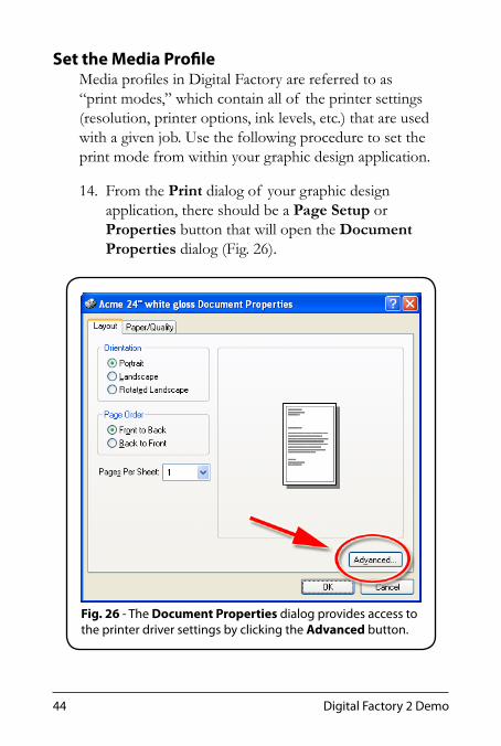
Set the Media ProfileMedia profiles in Digital Factory are referred to as “print modes,” which contain all of the printer settings (resolution, printer options, ink levels, etc.) that are used with a given job. Use the following procedure to set the print mode from within your graphic design application.
14. From the Print dialog of your graphic design application, there should be a Page Setup or Properties button that will open the Document Properties dialog (Fig. 26).
Fig. 26 - The Document Properties dialog provides access to the printer driver settings by clicking the Advanced button.

45Sending Jobs to Digital Factory
15. Click the Advanced button. The Advanced Options for the driver will open (Fig. 27).
16. Under Document Options, locate the Printer Features category and click the Print Mode field.
17. The Print Mode drop-list will become active.
18. Choose the print mode that is most appropriate for the media and image quality. Print modes are typically named according to media, print resolution, ink density, halftone frequency, and ink set.
Fig. 27 - In the printer driver settings, choose the Print Mode that will be used. Sending a File menu >> Print job in this fashion will override the print mode set within the Queue Properties dialog.

46 Digital Factory 2 Demo
Print&Cut
19. Click OK to close the Advanced Options.
20. Click OK again to close the Properties dialog.
21. Click OK to close the Print dialog, and the job will be received in Digital Factory.
In Digital Factory
22. In the Active List, the job thumbnail will have a knife icon to indicate that cut data has been located.
23. To see the cut paths in the Visual Print Manager, choose Show Print and Cut Previews from the drop-list.
24. If your queue is set to hold received jobs, then select the job and choose to either print, cut or print&cut from the Jobs menu.

47Sending Jobs to Digital Factory
Print&Cut
imporTing Designs DireCTly inTo DigiTal faCTory
Design files can be imported directly into Digital Factory, without the need to open the files in their original design applications. Use this workflow where you have a design file that must be printed without having access to the original design application. For example, the customer has sent you a design file, and you need to print the file “as is” without importing it into a design application.
Note: The supported image formats are subject to change, though common image formats are supported (e.g., EPS, AI, PDF, BMP, JPEG, TIFF, etc.).
In the following procedure, the gray boxes represent steps that are necessary in order to include cut paths with your print job (i.e., to create a print&cut job). If you wish to complete a print-only job, then skip the steps in gray.
In Digital Factory
1. From the toolbar, click the Start Queue button.
2. Choose Queue menu >> Properties >> Color Actions tab.
3. Click Add Color to define a specific vector color (CMYK or named) that Digital Factory will recognize as a cut path.
4. Click OK to close the Queue Properties dialog.
48 Digital Factory 2 Demo
Print&Cut
Print&Cut
In the Design Application
5. Prepare the print design.
6. Create a shape that will represent the cutting path.7. For the cut path shape, assign its fill to None, and
assign a hairline stroke that uses the color set in step (3).
8. Save the design file.For print&cut designs, the file must be saved in a format that supports stroke information (i.e., EPS, AI, PDF, etc.).
In Digital Factory
9. Load the design file using one of the following three methods:
a) Choose File menu >> Import File.
b) From the toolbar, click the Open button.
c) Drag-and-drop the file into the Digital Factory window.
10. In the Active List, the job thumbnail will have a knife icon to indicate that cut data has been located.
11. To see the cut paths in the Visual Print Manager, choose Show Print and Cut Previews from the drop-list.
12. If your queue is set to hold received jobs, then select the job and choose to either print, cut or print&cut from the Jobs menu.

49Sending Jobs to Digital Factory
senDing Jobs aCross a neTWorkUse this workflow when your design application is on a separate computer from where Digital Factory is installed. Once this configuration is complete, the File menu >> Print command will be used to send jobs across the network to Digital Factory.
Note: This workflow uses Windows remote printer sharing. If the design application is installed on a non-Windows computer, then please use the next workflow, “Sending Jobs from Non-Windows Computers.”
Note: For Windows remote printer sharing, the computers must be either BOTH 32-bit Windows, or BOTH 64-bit Windows. Otherwise, a mismatch between 32-bit and 64-bit will cause a Windows driver incompatibility that prevents jobs from proceeding.
In the following procedure, the gray boxes represent steps that are necessary in order to include cut paths with your print job (i.e., to create a print&cut job). If you wish to complete a print-only job, then skip the steps in gray.
In Digital Factory
1. From the toolbar, click the Start Queue button.
2. Choose Queue menu >> Manage Queues.
3. In the Control Panel column, click the Install button, such that the queue is available as a print destination for other Windows applications.
4. Click the Close button.

50 Digital Factory 2 Demo
Print&Cut5. Choose Queue menu >> Properties >> Color
Actions tab.
6. Click Add Color to define a specific vector color (CMYK or named) that Digital Factory will recognize as a cut path.
7. Click OK to close the Queue Properties dialog.
Enable Windows Remote Printer Sharing(On the computer that has Digital Factory)
8. From the Start menu, open the Windows Printers and Faxes (This is also available through the Control Panel).
9. In the list of printers, the queue name will be listed as one of the available printers.The Comments column will indicate that this is a “CADlink Printer,” and the Model column should indicate the printer model.
10. Right-click the queue name, and choose Sharing from the drop-list.
11. The Properties dialog will open, and the Sharing tab will be active.
12. Click the Share this printer option.
13. For the Share name, type a meaningful name. This name will appear to design computers when they are connecting to the Digital Factory computer.By default, Windows will initially truncate the share name to eight (8) characters, which is a precaution

51Sending Jobs to Digital Factory
Print&Cut
against incompatible filename lengths with older Windows versions.
14. Click OK to close the Properties dialog.
Connect to the Shared Printer(On the computer with the design application)
15. From the Start menu, choose My Network Places and browse the network to the (remote) computer that has Digital Factory.
16. In the top directory of the remote computer, the shared printer should be listed as a “CADlink Printer.”
17. Right-click the shared printer and choose Connect from the drop-list.
18. The printer will now be available through the File >> Print command of your design application.
Note: In the Windows Control Panel, a Digital Factory printer can be identified by opening its Properties dialog and inspecting the Ports tab.
In the Design Application
19. In the design application, prepare the print design.
20. Create a shape that will represent the cutting path.
21. For the cut path shape, assign an invisible fill, and create a hairline stroke that uses the color set in step (6).

52 Digital Factory 2 Demo
Print&Cut
22. Choose File menu >> Print.
23. From the Printer drop-list, choose the queue that had been designated in step (3).
24. The description for the printer (if any) should indicate that it is a “Visual Production Manager” or “CADlink” destination.
Note: It is possible for printer names to be quite similar to the queue name you have selected. If description does not indicate “Visual Production Manager” or “CADlink,” then check for a similar name from the Printer drop-list.
In Digital Factory
25. In the Active List, the job thumbnail will have a knife icon to indicate that cut data has been located.
26. To see the cut paths in the Visual Print Manager, choose Show Print and Cut Previews from the drop-list.
27. If your queue is set to hold received jobs, then select the job and choose to either print, cut or print&cut from the Jobs menu.

53Sending Jobs to Digital Factory
senDing Jobs from non-WinDoWs CompuTersThis workflow uses a specially designated Hot Folder (i.e., a directory on the hard drive). When design files are printed as a file to the Hot Folder, they will be automatically detected by Digital Factory and processed.Once configuration is complete, the File menu >> Print command (or equivalent) will be used to send jobs to Digital Factory. This configuration allows for design applications on non-Windows computers to print directly to Digital Factory.In the following procedure, the gray boxes represent steps that are necessary in order to include cut paths with your print job (i.e., to create a print&cut job). If you wish to complete a print-only job, then skip the steps in gray.
Create an Empty Hot Folder
1. Create an empty directory on your Digital Factory computer, or elsewhere on your network. This will be your Hot Folder, which must satisfy the following two conditions:
a) The Digital Factory computer must have login permission to read and write to the Hot Folder.
b) Your graphic designers must have file access permissions to write/copy files into the Hot Folder.
In Digital Factory
2. From the toolbar, click the Start Queue button.
3. Choose Queue menu >> Manage Queues.
54 Digital Factory 2 Demo
Print&Cut
Print&Cut
4. In the Control Panel column, click the Install button, such that the queue is available as a print destination for other Windows applications.
5. Click the Close button.
6. Choose Queue menu >> Properties.
7. Click the Hot Folders tab.
8. Tick the Enable Queue Hot Folder checkbox, which opens a browse dialog.
9. Browse to the Hot Folder that had been designated in step (1). Please note that the Hot Folder must be empty when it is initially chosen.
10. Click OK to accept the Hot Folder path.
11. Click the Color Actions tab.
12. Click Add Color to define a specific vector color (CMYK or named) that Digital Factory will recognize as a cut path.
13. Click OK to close the Queue Properties dialog.
In the Design Application
14. In the design application, prepare the print design.
15. Create a shape that will represent the cutting path.16. For the cut path shape, assign an invisible fill, and
create a hairline stroke that uses the color set in step (12).

55Sending Jobs to Digital Factory
Print&Cut
17. Choose File menu >> Print (or the equivalent according to the software being used).If it is permitted by the design software, then the design file can be “printed” to a data file that is placed directly into the Hot Folder. In this manner, printing will be seamless because Digital Factory will automatically process the file.Alternatively, save the design file in a commonly accepted format (e.g., EPS, AI, PDF, BMP, JPEG, TIFF, etc.), and copy the design file into the Hot Folder. However, for print&cut designs, the file must be saved in a format that supports stroke information (i.e., EPS, AI, PDF, etc.).
In Digital Factory
18. In the Active List, the job thumbnail will have a knife icon to indicate that cut data has been located.
19. To see the cut paths in the Visual Print Manager, choose Show Print and Cut Previews from the drop-list.
20. If your queue is set to hold received jobs, then select the job and choose to either print, cut or print&cut from the Jobs menu.

56 Digital Factory 2 Demo

57Additional Information
aDDiTional informaTionTo learn more about Digital Factory features and workflows:
□ Help File - Consult the Digital Factory Help File, which is available via Help menu >> Help Topics. Additional configuration workflows are provided, and each of the Digital Factory features are explained in greater detail.
□ User Guide - The bound Digital Factory User Guide is provided upon purchase of Digital Factory, which contains additional configuration workflows and detailed explanations of Digital Factory features.
□ InfoSource - Review demonstration and training videos that are available through the CADlink web site ( www.cadlink.com ). These videos include both overviews and in-depth examples of how to use Digital Factory features.


