FCC Notice This equipment has been tested and found to comply with the limits for a Class A digital device, pursuant to part 15 of the FCC Rules. These limits are designed to provide reasonable protection against harmful interference when the equipment is operated in a commercial environment. This equipment generates, uses, and can radiate radio frequency energy, and if not installed and used in accordance with the instructions manual, may cause harmful interference to radio communications. Operation of this equipment in a residential area is likely to cause harmful interference in which case the user will be required to correct the interference at his own expense.
Any changes or modifications to the equipment not expressly approved in this manual may void the user’s authority to operate the equipment.
European Community Compliance The Digital Model 10 and Model 20 are both CE marked and conform to the following product specifications:
1. Getting Started Thank you for purchasing Rank Brothers equipment. Please ensure that you have read and understood this operating manual before use. You should safely store this manual for future reference.
1.1 Do Not
Do not plug into your local mains supply until you have checked that your supply voltage matches that stated on the label at the rear of the instrument (adjacent to the mains inlet connector).
Do not change the fuse or remove any covers while the mains inlet lead is still connected to the unit.
1.2 Do
Do ensure that if the moulded plug is removed from the mains lead it is safely disposed of.
Do ensure you have read and understood this manual before using the instrument.
1.3 Connection to your Mains Supply
IMPORTANT: This unit must be earthed to ensure operator safety. The mains inlet lead may have a moulded plug fitted that is not suitable for connection to your local supply. If it is necessary to remove this plug and fit a suitable one, the removed plug must be safely disposed of. The removed plug would present a serious shock hazard if plugged into a suitable supply with the bare wires exposed.
The wires of the mains inlet lead are coloured as follows:
GREEN and YELLOW EARTH BLUE NEUTRAL BROWN LIVE
As the colours of the wires in the mains lead may not correspond with the coloured markings identifying the connections in your plug, proceed as follows:
The GREEN and YELLOW coloured wire must be connected to the terminal in the plug that is either marked with the letter E or marked with the earth symbol or coloured GREEN or coloured GREEN and YELLOW.
The BLUE wire must be connected to the terminal marked N or coloured BLACK.
The BROWN wire must be connected to the terminal marked L or coloured RED.
Before connecting the unit to your mains supply ensure that your supply voltage matches that on the label at the rear of the instrument (adjacent to the inlet connector).
Digital Model 10 and Model 20 Controller
6
For operator safety any blown fuse must be replaced with one of the correct type and rating. Before changing a fuse, switch off the mains supply and disconnect the mains inlet lead from the instrument. The fuse for both the Model 10 and the Model 20 is located at the bottom of the mains inlet connector at the rear of the instrument. The correct fuse values are as follows:
220/240 V T80mA 100/110 V T100mA
The instrument contains no user serviceable parts. The base cover should be removed by competent personnel only (after first switching off the power supply and disconnecting the mains inlet lead).
To carry out any servicing or repairs the instrument should be returned to the manufacturer with a covering letter. Please ensure that the instrument is carefully packaged to avoid damage during shipment.
2. Controls
2.1 Mains On/Off Switch
The Power On/Off switch is located on the top right hand side of the front panel. When switched on, the adjacent neon indicator will light and the display will be illuminated.
2.2 Stirrer On/Off Switch
This switch is located on the bottom right hand side of the front panel. The stirrer can be turned on and off using this switch.
2.3 Stirrer Speed Control
Located next to the Stirrer On/Off switch, this allows the stirring speed to be adjusted from approximately 120 rpm to 1200 rpm. Suitable stirring should be obtained at a setting of 6. Note for the stirrer to operate correctly the stirring bar must contain a magnet, just using magnetic material (e.g. a paper clip) will produce a jumping action instead of a smooth rotation.
2.4 Polarising Volts Switch
This switch selects whether the display is reading the polarising voltage or the percentage saturation of oxygen. By default the display shows the percentage saturation of oxygen. When the switch is held down the display reads the polarising voltage in volts. When released the display reads the percentage saturation.
Rank Brothers Ltd
7
2.5 Polarising Volts Control
The control below the Polarising Volts switch allows adjustment of the polarising voltage applied to the electrode. A voltage of 0.6 V is suitable for our electrodes, although it can vary between 0 and 1 volts approximately. Note a reading of 0.6 V indicates that the platinum electrode is polarised −0.6 V with respect to the silver electrode.
2.6 Set Zero Control
This control zeroes the amplifier circuit ensuring that the display reads zero when there is no electrode connected. It is advisable to allow at least 5 minutes warm up period before adjusting this control. The control can also be used to offset the residual current flow in the electrode when no oxygen is present. This control requires a small screwdriver to make adjustments.
2.6.1 Set Zero Controls (Model 20 only)
There are two Set Zero controls on the Model 20, one for each electrode.
2.7 Sensitivity Control
The Sensitivity control is a 10-turn control and is used to calibrate the electrode when filled with liquid of known oxygen content, typically air saturated water.
2.7.1 Sensitivity Controls (Model 20 only)
The Sensitivity controls are 20-turn preset controls and require a small screwdriver for adjustment. They are labelled 1 and 2 corresponding to the electrode they affect.
2.8 Display Selector Switch (Model 20 only)
The display selector switch located under the display selects which electrode’s data is being displayed. When switched to the left (position 1) the display shows the reading from the electrode plugged into the left socket (labelled 1). When switched to the right, the display shows the reading from the electrode plugged into socket 2. Therefore it may be more convenient to plug the left-hand electrode into socket 1 and the right hand electrode into socket 2.
3. Connections
3.1 Electrode Socket
The electrode socket is a 3-pin DIN socket and allows connection to an oxygen electrode. Rank Brothers electrodes are supplied suitably wired to a 3-pin DIN plug. The connections to a 3 pin DIN Plug are as follows:
Pin 1 Silver Electrode (Red wire) Pin 2 Not Connected
Digital Model 10 and Model 20 Controller
8
Pin 3 Platinum Electrode (Blue wire)
The cable screen should be connected to the strain relief clamp in the plug.
3.1.1 Electrode Sockets (Model 20 only)
The electrode sockets are 3-pin DIN sockets each allowing the connection of one oxygen electrode. The sockets are labelled 1 and 2 so that the appropriate controls can be selected for each electrode. Rank Brothers electrodes are supplied suitably wired to a 3-pin DIN plug.
3.2 Recorder Socket
The recorder socket is a BNC type and is situated at the rear of the instrument. It can be connected to either a chart recorder or a data-logging device. The output is typically 1 volt when the display reads 100.0. The instrument is supplied with a ‘BNC to 4 mm banana plugs’ lead suitable for use with most chart recorders.
3.2.1 Recorder Sockets (Model 20 only)
The Model 20 has two recorder sockets, one for each electrode, situated at the rear of the instrument. With two electrodes connected the outputs from both electrodes are available simultaneously and may be connected to either a dual pen chart recorder, or a dual channel data logger. The outputs are at 1 volt when the display reads 100.0. The instrument is supplied with two chart recorder leads.
4. Operation
4.1 Operating Stand Alone
1. Plug the instrument into your mains supply, switch on and allow 5 minutes warm up. Ensure the electrode is not plugged in.
2. Adjust the Set Zero control until the display reads zero. 3. Adjust the polarising volts control until a suitable polarising voltage is set (typically
0.6 V). Depress the Polarising Volts switch so that the display monitors the voltage. 4. Plug in an oxygen electrode that has been set up with water in the incubation
chamber (see section 5.4 below). 5. Sit the electrode on the stirring head and lock off with the white plastic retaining
screw. 6. Circulate water through the electrode incubation chamber and allow the sample
temperature to stabilise. 7. Switch on the stirrer and adjust the stirring speed, typically about 6 on the knob is
suitable. 8. Bubble air through the water and allow the reading to stabilise. 9. The Sensitivity control can now be adjusted until the display reads 100.0 percentage
saturation.
Rank Brothers Ltd
9
10. Purge all the oxygen from the sample either with a few crystals of sodium dithionite, or by bubbling nitrogen through.
11. If the display does not read zero, this is due to residual current flow in the electrode, and can be trimmed out with the Set Zero control.
12. Adjusting the Set Zero will affect the calibration, so repeat steps 8, 9, 10 and 11 as necessary. The electrode is now calibrated and ready for use.
4.1.1 Operating Stand Alone (Model 20 only)
Each step in section 4.1 must be repeated for both electrodes.
4.2 Operating with a Chart Recorder
Any chart recorder that can accept a 1.0 V full-scale input would be suitable to connect to the recorder output socket at the rear of the instrument.
1. Once the electrode is calibrated (see section 4.1) connect the chart recorder with the supplied recorder lead.
2. Switch on the chart recorder and select an appropriate input range (1 V if available). The chart recorder should now read full scale providing that the controller is displaying 100.0.
3. If the recorder reading does not correspond to the display reading, the Sensitivity control can be used to calibrate the recorder rather than the display, if preferred.
4. Select an appropriate chart feed rate and allow the recorder to monitor your experiment.
4.3 Operating with a Data Logger
A data logger will allow your experiment to be recorded and then transferred to a computer. Typically lower cost loggers plug into the computer and only operate while the computer is operating, whereas more expensive units operate independently from the computer and are only linked to download data. Most software supplied with these units allows the data to be exported to a spreadsheet, where further processing can be carried out, results printed and graphs generated. Consult the logger instructions for operation, but ensure that its inputs are able to accept 1.0 V input and are protected to withstand at least 5 V. Select a model with a suitable resolution remembering that the controller display has a resolution of 1 mV. A logger with a 5 V full-scale input and 12 bits (212) resolution will thus have a resolution of about 1.25 mV (5/212). The supplied recorder lead may not be appropriate for your logger, a special lead may be required.
4.4 Troubleshooting
Possible Causes Suggested Remedies
Display and indicator fail to illuminate.
Instrument switched off. Ensure the instrument is on.
Fuse in instrument failed. Replace fuse in instrument.
Digital Model 10 and Model 20 Controller
10
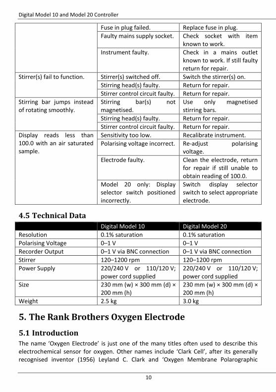
Fuse in plug failed. Replace fuse in plug.
Faulty mains supply socket. Check socket with item known to work.
Instrument faulty. Check in a mains outlet known to work. If still faulty return for repair.
Stirrer(s) fail to function. Stirrer(s) switched off. Switch the stirrer(s) on.
Stirring head(s) faulty. Return for repair.
Stirrer control circuit faulty. Return for repair.
Stirring bar jumps instead of rotating smoothly.
Stirring bar(s) not magnetised.
Use only magnetised stirring bars.
Stirring head(s) faulty. Return for repair.
Stirrer control circuit faulty. Return for repair.
Display reads less than 100.0 with an air saturated sample.
Sensitivity too low. Recalibrate instrument.
Polarising voltage incorrect. Re-adjust polarising voltage.
Electrode faulty. Clean the electrode, return for repair if still unable to obtain reading of 100.0.
Model 20 only: Display selector switch positioned incorrectly.
Switch display selector switch to select appropriate electrode.
4.5 Technical Data
Digital Model 10 Digital Model 20
Resolution 0.1% saturation 0.1% saturation
Polarising Voltage 0–1 V 0–1 V
Recorder Output 0–1 V via BNC connection 0–1 V via BNC connection
Stirrer 120–1200 rpm 120–1200 rpm
Power Supply 220/240 V or 110/120 V; power cord supplied
220/240 V or 110/120 V; power cord supplied
Size 230 mm (w) × 300 mm (d) × 200 mm (h)
230 mm (w) × 300 mm (d) × 200 mm (h)
Weight 2.5 kg 3.0 kg
5. The Rank Brothers Oxygen Electrode
5.1 Introduction
The name ‘Oxygen Electrode’ is just one of the many titles often used to describe this electrochemical sensor for oxygen. Other names include ‘Clark Cell’, after its generally recognised inventor (1956) Leyland C. Clark and ‘Oxygen Membrane Polarographic
Rank Brothers Ltd
11
Detector’ (O2-MPD for short), because of the mode of action of the electrochemical device.
The Oxygen electrode remains one of the most commonly used devices for measuring the partial pressure of oxygen (sometimes referred to as ‘oxygen tension’) in the gas phase or, more commonly, dissolved solution. The Oxygen Electrode finds application in a wide variety of diverse subject areas including environmental studies (e.g. O2-levels in natural waters), sewage treatment (vital in monitoring the progress of bacterial attack), alcohol production (O2-levels in fermentation tasks need to be continuously monitored and controlled) and medicine (invasive and non-invasive monitoring of a key physiological analyte). The typical range of detection of O2 of this device is from 10
−4 atm (i.e. 0.01%) to 1 atm
(i.e. 100%). The key to continuing supremacy of the Oxygen Electrode over other electrochemical devices for O2 detection is the utilisation of a gas-permeable, ion-impermeable, membrane that separates the test system from the sensing electrode (the platinum cathode). This membrane prevents many problems of electrode passivation or poisoning that arise when the sensing electrode is placed in direct contact with the system (usually an aqueous solution) under test.
5.2 The Cell
The Rank Brothers Oxygen Electrode comprises two electrodes. The first is a small (typically 2 mm in diameter) central platinum disc working electrode (this is the cathode and it is at this electrode that the O2 diffusing through the membrane is reduced). Set in a well surrounding this is a silver ring counter and reference electrode (about ten times larger in surface area than the platinum cathode). Conduction between the two electrodes is achieved using a 3M
Digital Model 10 and Model 20 Controller
12
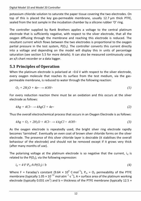
potassium chloride solution to saturate the paper tissue covering the two electrodes. On top of this is placed the key gas-permeable membrane, usually 12.7 µm thick PTFE, sealed from the test sample in the incubation chamber by a silicone rubber ‘O’ ring.
The controller supplied by Rank Brothers applies a voltage to the central platinum electrode that is sufficiently negative, with respect to the silver electrode, that all the oxygen diffusing through the membrane and reaching this electrode is reduced. The resultant current which flows between the two electrodes is proportional to the oxygen partial pressure in the test system, P(O2). The controller converts this current directly into a voltage and depending on the model will display this in units of percentage saturation (see section 5.5 for more details). It can also be measured continuously using an x/t chart recorder or a data logger.
5.3 Principles of Operation
When the platinum electrode is polarised at −0.6 V with respect to the silver electrode, every oxygen molecule that reaches its surface from the test medium, via the gas-permeable membrane, is reduced to water through the following reaction:
O2 + 2H2O + 4e− → 4OH− (1)
For every reduction reaction there must be an oxidation and this occurs at the silver electrode as follows:
4Ag + 4Cl− → 4AgCl + 4e− (2)
Thus the overall electrochemical process that occurs in an Oxygen Electrode is as follows:
4Ag + O2 + 2H2O + 4Cl− → 4AgCl + 4OH− (3)
As the oxygen electrode is repeatedly used, the bright silver ring electrode rapidly becomes ‘tarnished’. Eventually an even coat of brown silver chloride forms on the silver electrode. The presence of this silver chloride layer is desirable (it stabilises the overall behaviour of the electrode) and should not be removed except if it grows very thick (after many months of use).
The polarising voltage at the platinum electrode is so negative that the current, id is related to the P(O2), via the following expression:
id = 4·F·Pm·A·P(O2) / b (4)
Where F = Faraday’s constant (9.64 × 10⁴ C·mol
−1), Pm = O2 permeability of the PTFE
membrane (typically 1.05 × 10⁻¹²
mol·atm−1
·s−1
), A = surface area of the platinum working electrode (typically 0.031 cm
2) and b = thickness of the PTFE membrane (typically 12.5 ×
Rank Brothers Ltd
13
10−4
cm). Thus in a test medium which is air-saturated water, P(O2) = 0.2 atm, the oxygen electrode would have a value for id of 2 µA approximately.
5.4 Setting up the Oxygen Electrode
Apart from the electrode itself you need to have the following items:
Small pair of sharp scissors.
3M potassium chloride solution.
Teat pipette.
PTFE membrane (supplied by Rank Brothers).
Tissue paper (lens tissue is ideal, but one ply of ordinary tissue is fine).
1. Using the teat pipette, wet both electrodes and fill the small well containing the silver electrode with the potassium chloride solution.
2. Cut a 1.5 cm square piece of tissue paper with a 2 mm hole in its centre and float this on the potassium chloride in the well ensuring that the hole is central above the platinum electrode.
3. Touch the empty teat pipette against the tissue paper and use it to suck off the excess electrolyte so that the paper is wet (but not very wet) and clings to the surface of the electrode.
4. Cut a 1.5 cm square piece of PTFE membrane and place it so that it covers both electrodes, ensuring that the platinum electrode is underneath the centre membrane and that there are no air bubbles trapped under the membrane.
5. Gently push the silicone rubber ‘O’ ring over the platinum electrode so as to hold the PTFE membrane in place when the plastic base and the incubation chamber are clamped together (you can use the incubation chamber to gently push the ‘O’ ring into place).
6. Carefully clamp the electrode base and the incubation chamber together. It is important to ensure that the incubation chamber is not rotated on the base during clamping, as this will damage the membrane. The locking ring should be tightened by hand only. Over tightening may cause problems.
7. Connect the electrode to the controller, adjust the polarising voltage to 0.6 V and adjust the stirring speed to a suitable level. Connect the water jacket of the incubation chamber to a constant temperature water bath and allow the sample temperature to stabilise. The electrode is now ready for calibration.
5.5 Calibrating the Oxygen Electrode
The controller converts the current from the electrode to a voltage thus if S is the voltage from the controller, it is proportional to the partial pressure of O2 in the medium under test:
S = K·P(O2) (5)
Digital Model 10 and Model 20 Controller
14
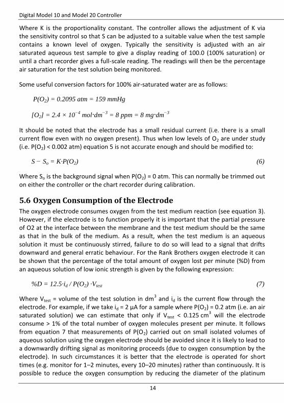
Where K is the proportionality constant. The controller allows the adjustment of K via the sensitivity control so that S can be adjusted to a suitable value when the test sample contains a known level of oxygen. Typically the sensitivity is adjusted with an air saturated aqueous test sample to give a display reading of 100.0 (100% saturation) or until a chart recorder gives a full-scale reading. The readings will then be the percentage air saturation for the test solution being monitored.
Some useful conversion factors for 100% air-saturated water are as follows:
P(O2) = 0.2095 atm = 159 mmHg
[O2] = 2.4 × 10⁻⁴
mol·dm−3
= 8 ppm = 8 mg·dm−3
It should be noted that the electrode has a small residual current (i.e. there is a small current flow even with no oxygen present). Thus when low levels of O2 are under study (i.e. P(O2) < 0.002 atm) equation 5 is not accurate enough and should be modified to:
S − So = K·P(O2) (6)
Where So is the background signal when P(O2) = 0 atm. This can normally be trimmed out on either the controller or the chart recorder during calibration.
5.6 Oxygen Consumption of the Electrode
The oxygen electrode consumes oxygen from the test medium reaction (see equation 3). However, if the electrode is to function properly it is important that the partial pressure of O2 at the interface between the membrane and the test medium should be the same as that in the bulk of the medium. As a result, when the test medium is an aqueous solution it must be continuously stirred, failure to do so will lead to a signal that drifts downward and general erratic behaviour. For the Rank Brothers oxygen electrode it can be shown that the percentage of the total amount of oxygen lost per minute (%D) from an aqueous solution of low ionic strength is given by the following expression:
%D = 12.5·id / P(O2) ·Vtest (7)
Where Vtest = volume of the test solution in dm3 and id is the current flow through the
electrode. For example, if we take id = 2 µA for a sample where P(O2) = 0.2 atm (i.e. an air saturated solution) we can estimate that only if Vtest < 0.125 cm
3 will the electrode
consume > 1% of the total number of oxygen molecules present per minute. It follows from equation 7 that measurements of P(O2) carried out on small isolated volumes of aqueous solution using the oxygen electrode should be avoided since it is likely to lead to a downwardly drifting signal as monitoring proceeds (due to oxygen consumption by the electrode). In such circumstances it is better that the electrode is operated for short times (e.g. monitor for 1–2 minutes, every 10–20 minutes) rather than continuously. It is possible to reduce the oxygen consumption by reducing the diameter of the platinum
Rank Brothers Ltd
15
electrode, however the current flow is also reduced putting more demands on the controller.
It should be noted that although P(O2) and therefore id is independent of salinity, the actual concentration of O2 in solution decreases with increasing salinity (see reference 1). As a result of this the factor 12.5 in equation 7 increases with increasing salinity (it is ≈ 29 in 3M sodium chloride). Thus care should be taken when monitoring low oxygen levels in isolated low volume solutions of high ionic strength.
5.7 Temperature Sensitivity of the Oxygen Electrode
The oxygen electrode is temperature sensitive and should be thermostatted whenever this is possible. If no thermostatting is employed the signal is likely to increase with increasing temperature. If the thermostatting is inadequate the signal will fluctuate as the oxygen electrode and sample change temperature. Any light shining on the electrode may cause a change in signal due to heating effects.
5.8 Cleaning and Storing the Oxygen Electrode
When the electrode is not in use for a few hours (e.g. overnight) it is best dismantled and the electrodes left to soak in distilled water, we can supply a storage cell for this purpose. If the electrode assembly must be left intact, but non-operational for a few hours, it is best if the electrode is left on, but with the stirrer switched off. The platinum electrode needs to have a ‘mirror’ finish, any surface damage will affect the response of the electrode, and it will thus need to be cleaned approximately once every 5–7 days of use or when it has lost its shine. A suitable polish can be made by mixing a thick slurry of 0.3 µm polishing alumina (obtainable from BDH Chemicals & Merck for instance) in distilled water. A piece of cotton wool can then be used to polish the platinum electrode until it is smooth, bright and clean (this should only take a few minutes). The silver electrode will need to have the layer of silver chloride removed and the surface polished every 2–3 months of use. A 10% ammonia solution on cotton wool can be used to remove the silver chloride layer. (Ensure that the appropriate handling precautions are observed.) The silver electrode can then be made smooth, bright and clean by polishing with the alumina slurry as described above for the platinum electrode.
5.9 Troubleshooting
Simply dismantling the electrode, washing it in distilled water and then re-assembling with a new membrane and fresh potassium chloride can solve most problems encountered with the oxygen electrode. A useful check to see if the electrode is responding properly is to alter the P(O2) in the test solution. This can be done by saturating with air, or by removing all oxygen from the test medium by purging with nitrogen (or any inert gas, such as He or Ar) or by adding sodium dithionite. The signal should change very rapidly (typically giving a 90% response within 15 seconds) with a
Digital Model 10 and Model 20 Controller
16
sudden change in P(O2). The observation of some signal noise that is synchronised with the stirrer flea rotations is a useful indication that the electrode is working well.
Symptoms Possible Causes Suggested Remedies
Noisy signal. Electrical interference. Remove the electrode from the source of noise.
Stirrer flea in contact with the membrane.
Ensure the flea is the correct size (it is usual to have some signal noise synchronised with the stirrer flea rotations).
Sluggish or no change in signal with changes in oxygen level.
Incubation chamber clamped too tight.
Reassemble the electrode. The locking ring should be hand tight only.
Insufficient electrolyte soaking the tissue.
Reassemble the electrode.
Air bubble above platinum electrode.
Remove the air bubble with teat pipette.
Membrane damaged. Reassemble the electrode.
Stirrer flea stopped. Check stirrer is switched on and operating OK.
Platinum electrode damaged.
Polish the electrode or return to us for repair.
Step change in signal. Stirrer flea had stopped turning and now has started again.
Check stirrer is functioning correctly and the flea is OK.
Smooth but rapid increase in signal.
Hole in membrane (the test solution has begun to leak into the electrolyte well).
Reassemble the electrode with a new membrane.
Smooth but slow increase in signal with constant oxygen level.
Inadequate thermostatting. Improve the thermostatting.
The electrode is being warmed up (e.g. by direct sunlight).
Shade from direct sunlight.
Downwardly drifting signal. Air bubble above platinum electrode.
Remove the bubble with teat pipette.
Hole in membrane. Reassemble the electrode.
Stirrer flea stopped turning. Check the stirrer and flea are OK.
much oxygen. samples high in ionic strength, low in volume (< 1 cm
3) and low in oxygen
(< 5% saturated).
5.10 Technical Data
Each electrode is supplied with a screened lead connected to a DIN plug, 50 mm × 450 mm of PTFE membrane, 1 stirring bar (flea), and 1 ‘0’ ring for the PTFE membrane.
Oxygen Electrode
Size 50 mm × 100 mm × 50 mm approx.
Weight 100 g approx.
Response Time 100–0% air saturation in less than 15 seconds
6. Suggested Further Reading 1. M L Hitchman, Measurement of Dissolved Oxygen, 1978, Wiley-Interscience,
London, ISBN 0-471-03885-7. 2. Y H Lee and G T Tsao, Advances in Biochemical Engineering, 1979, Volume 13, Page
35.
7. Acknowledgements We gratefully acknowledge the help and assistance given by Professor Andrew Mills, University of Strathclyde in compiling this manual.
Digital Model 10 and Model 20 Controller
18
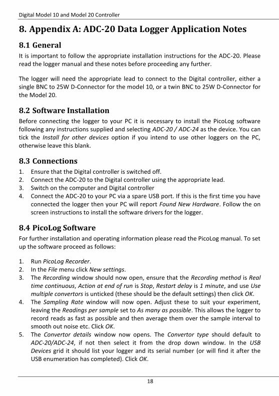
8. Appendix A: ADC-20 Data Logger Application Notes
8.1 General
It is important to follow the appropriate installation instructions for the ADC-20. Please read the logger manual and these notes before proceeding any further.
The logger will need the appropriate lead to connect to the Digital controller, either a single BNC to 25W D-Connector for the model 10, or a twin BNC to 25W D-Connector for the Model 20.
8.2 Software Installation
Before connecting the logger to your PC it is necessary to install the PicoLog software following any instructions supplied and selecting ADC-20 / ADC-24 as the device. You can tick the Install for other devices option if you intend to use other loggers on the PC, otherwise leave this blank.
8.3 Connections
1. Ensure that the Digital controller is switched off. 2. Connect the ADC-20 to the Digital controller using the appropriate lead. 3. Switch on the computer and Digital controller 4. Connect the ADC-20 to your PC via a spare USB port. If this is the first time you have
connected the logger then your PC will report Found New Hardware. Follow the on screen instructions to install the software drivers for the logger.
8.4 PicoLog Software
For further installation and operating information please read the PicoLog manual. To set up the software proceed as follows:
1. Run PicoLog Recorder. 2. In the File menu click New settings. 3. The Recording window should now open, ensure that the Recording method is Real
time continuous, Action at end of run is Stop, Restart delay is 1 minute, and use Use multiple convertors is unticked (these should be the default settings) then click OK.
4. The Sampling Rate window will now open. Adjust these to suit your experiment, leaving the Readings per sample set to As many as possible. This allows the logger to record reads as fast as possible and then average them over the sample interval to smooth out noise etc. Click OK.
5. The Convertor details window now opens. The Convertor type should default to ADC-20/ADC-24, if not then select it from the drop down window. In the USB Devices grid it should list your logger and its serial number (or will find it after the USB enumeration has completed). Click OK.
Rank Brothers Ltd
19
6. The ADC-20 Channels window will open showing the 8 channels available. Ensure that you select the correct Mains Frequency at the bottom to ensure best rejection of any mains related noise.
7. Now highlight Channel 1 and click on Edit. In the Edit ADC-20 Channel window click in the Name box and rename this to Electrode 1, or similar. The Conversion Time can be left at 60 ms and in the Voltage Range box select ±2.500V. The Differential input enable option MUST BE TICKED.
8. Click Options…, the Parameter options window opens. Tick Use Parameter Formatting, rename units to %age Sat, or similar, and adjust the Number display and Scaling for graphs as appropriate. (Field width: 4, Decimal places: 1, Minimum value: 0, Maximum value: 120 (a higher value can be used if required) should be suitable).
9. Click Scaling, and select Equation as the Scaling method. Set the scaling to −X/10 (this divides the reading by ten and makes it positive so that the reading should be very close to the display on the Digital controller).
10. Click OK on each opened window until you return to the ADC-20 Channels window. 11. For a Model 20 controller repeat steps 7 to 10 selecting Channel 3 to edit and
renaming this Electrode 2 or similar. Note that channel 2 will be unavailable as differential input was selected for channel 1.
12. Click OK on the ADC-20 Channels window to return to the PLW Recorder window displaying the channels and their current readings. These should correspond closely to the readings on the Digital controller, however they are unlikely to be exactly the same. If the error is unacceptable, adjust the scaling as in step 9 above to correct the error. It may be worth removing the electrode from the Digital controller and with the reading at 0.0, ensure that the logger reads 0.0. If not an offset can be applied in the scaling (e.g. −X/10 + 0.5). Note it is unlikely that you will be able to scale the readings to give exactly the same values as the Digital controller over the entire output range, although it should be possible to reduce the error to less than 1%.
13. In the Settings menu click Sampling… and adjust the number and interval of the readings to record, then click OK. A sample interval of 1 second and maximum of 500 readings is a good starting point.
14. From the PLW Recorder window click the New file icon in the top left of the window and enter a filename.
15. To start logging click on the Start Recording icon. To abort the recording click the Stop recording icon.
16. To view either a spreadsheet or a graph of the readings click on the appropriate icon at the top right of the window. Use the Select channels icon in the graph or spreadsheet window to select which channels are displayed.
17. When the recording has stopped, from the PLW Spreadsheet window click the Select icon to select the whole sheet, then click the Write to disk icon giving the file an appropriate name. The file will be saved with a prn extension that can be opened in most spreadsheet programs to allow further processing of the data.
Digital Model 10 and Model 20 Controller
20
The above information is correct for release 5.21.1 of the PicoLog software. Other features and facilities are available and further information is available in the manual.


![Model View Controller float sales[3][4]; model: controller: views: PowerPoint presentation by Cameron Hayne September 2003.](https://static.documents.pub/doc/80x56/56649eb25503460f94bb883c/model-view-controller-float-sales34-model-controller-views-powerpoint.jpg)


