20

Double excitation theory-Induction Motor
4.1 MTRODUCnrON
In chapter-111, it has been ma~t iod that t& time hrmonics will be g d
in tbc supply due to switching device& Wbcn clcdic motors m givcn wch a wpply,
the iron lows would increase wnsidmbly, especially if the rotor is a solid one. The
iron losses in thc solid-iron rotor caa be estimated by representing thc mn-linear
excitation as thc sum of fundamental and the harmonic of highest magnitude. But thc
test bas been performed on single-phase induction motor by feubg thc fundamental
excitation al 50 Hz and the harmonic excitation at 450 Hz. This type of problem can
be called as rmnxcitation problem or dual excitation problem. One would come
rrrou two excitation pmblem in the feedbeck control systems, where to stabilize the
main signal, a high Freqwncy signal is ycacd in to h e system, of-course the
frequency spatation be~wecn thc IW signals is high. The numerical solution of the
tmrsxcilrtion field problem is achieved by W o - S p t r a l Method [13].
A canpulcnrd gnphiul method is rlso dcvclopd to fd the field distribution.
The theory developed in chap&-Ill, to find h e various quantities like power
Imtu. fluxes CIC, haJ been verified witb tb: prtical results of single-phase induction
motor mth dual exciwon. The 14 lo- on the -or side arr estimated using the
m h i m design thrary 1241. The infinite half-specc h r y is applied to the actual
rotor by modifying thc resistivity of the rotor material with the correction factors for
curvalw and cnd effccls 1141. A wmction factor IS also incarparaled for
~mqmrturc risr. l'hc interfcmcc bctwcen thc IWO input signals with regard to IIIC
windrnga ia avoided. Since thc decaicrl ~k b*wben the wind~ngs is 90'.

4 3 DEMRHTION OF THE PROBLEM
Tbc h c e d h m i i field in the rotor of poly-phase induction motor can be
made two dimensional, if it is Pllrnuacd tha! the i n d d eddycumnts in the rotor arc
in widdirection only. The rotor cm be vicwed as an iron- block, wficn its curvatm
is neglected. Such an iron -block is subjected to travelling field on its surface say in
y-z plane, it is obvious that, thm c x h m altmahg flux through any section
pafallel to x-z plane, d m w i n g a dip frrquency. Conscqucntly, the evaluation of
eddy-cwent losses in solid-iron rotor of an induction machim an be based on the
knowledge of eddycurrefit distribution in an infinite half-space of iron subjected to
pulsating ticld.
Solid-iron mlor induction motors are in use. Due to many reasons, these
motors operate from non-sinusoidal excitation. Such an excitation can be considered
to be the sum of fundamanal and the harmonic of highest magnitude for the purpose
of evaluating cddy-currcnt losses. 'herefore, for analysing cddycumnt losses in
elccuic mhna, the input is taken cu the sum of two sinusoidal signals of
comnaammtc h a q w i a . h f o n . tmwxcitation field problem is simulated using
single-phase induction mtor with two windings.
The pmblem has been formulate4 in section 2.5. But the boundary conditions
arc provided in section 3.5 (qa(3.38)) Remite the equation (2.41 ) for convenience
The consmb arc a = 2.25 Tala and y "787 Mm for the g i m mrgnctiuuion c u m
oftheMnaidurhowninfigurr4.l.

Fi4.l: B-H curve
Tht bounduy and initial conditions sre nmim here as follows:
(iii) Initial values i.c at T = 0, t i = 0 for all "xn

4 3 SOLUTION OF THE PROBLEM-PSM
In d o n 3.2, the dyt ica l solution ia developed for the problan. 'lbe same
pmblan is dso solved numerically by using Cd-Nicholson Mcthod in d o n 3.5.
But in ckptcr-Il. it has been dated that the P&Speceal Method can be a good
substitute for Cnak-Nichoh Method. Heace, in this chqm, the duel excitation
p b l a n is solved by Speclral method.
43.1 Implieit Pseudo S@ Method
In section 2.6, Pseudo Spectral Method or Chebyshev collocation metbod is
discwed elabomtely. The implicit b s l c p p i q scheme IO equation (4.1) is given by
quation (2.67) i.c.,
It may k noted thu to fud t&: values of H at (n+l) timc-step the derivatives ue
mluued at (n+l) timeslep itself. The boundary conditions of equation (4.2) me
implemented by changing the entries of first-row and lapr-row of coefficient maaix
'D' by referring section (2.61). Then Ihe equation (4.3) is solved for Wing the field
d~stnbution. Foc chc sw l rc excitation of H I S = I 1518 A/m, at u1=314.2 dps .
Hn -2303 Nm, at to? 2827.11 nd/sec. the field distribution at various layas is
shorn in figwr 4.2


43.2 Jhahtion of eddy camot ku
Once the field Wbution is abteined thc iron 11x1s ten be c a l M using the
pmculm cncW in section 3.5. In this chapter the effect of harmonics w iron
losses is alao considend.
For this purpose, along with thc f h d a m d compowm, various lmmoaic
cornponenu of field ~IX determined at various laycn, unseqwtly, the cumnt
densities M dusted wing the formula give by equation (3.41) as
Foreschvalueof j =13 : f ix h = 1.3.5. andrunk=OtoN.
Thc figure 4.3 shows the profile of fundmental and harmonic c m t
densities, wbcn the surface excilations me H I S = 1 1518 Aim, at wr=3 14.2 rad/scc; aod
Ha - 2303 A h , at a11 = 2827.8 d s c c .
From Ihc figure 4.3. it is undascnd tbac the higb frequmcy signal mcnuats
fraP tha low frequency signal confuminp the validity of equation (2.38) with rrspea
IO f'rcqucacy. Monovcr. Ihc menuation is nonlinear with depth.
Fowia series is employed to scpmk the fmdamentd components at eacb
laya fmm Ihc resultant wave. Therefore, it has been assumed lhat the two finqumcy
signals uc cammmlurau at all laym. For the incommmsurate signals at the surface.
I! ir diffwult to #pantc thc fundamental components in interior of the materid. In
fm it will bc very intntsling to find the ways to separate Ihc h c n l a l
eompone~b of incommcnsmte signals from the distortad resultant fidd.
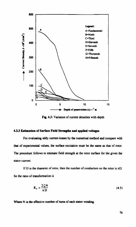
Fig. 43: Variation of cumnt densities with depth
4 3 3 Esttmrtion 01 Surface Fkkl Swcmgtlu .ad applkd voltage
For evalunting eddy current-losses by the numerical method aad compare with
h of expcrimartai values, the surface excitation must be the oame as that of rotor.
The procedure follows to estimate field strength at the rotor surface for the given the
stator current.
If D is the diameter of rotor, then the number of conductors on the mtor i s nD.
So h e ratio of vansfonnalion i s
Where N is rhc e f f d v e number of tumr of e& stator windiag.

IftbctWophrrslhvc~urlpumber~ftums*then
~*(NI+N~)/NI fortheihtwinding
5 = ( N I + N ~ ~ N ~ for the second winding
Let Hs k tbc m a p t b i q force at the d a c e of iron in Arnp/m. Ttsen the equivalent
r.m.8 cunmt of the rotor refand to the stator is
I , =- Hs (or) f i K,
Since, it has been observed practically that the magnetising cumnt draw by solid
imn rotor induction motor is as high as 30%. If one assumes the angles between
voltage & I, and vollage & I, arc 36' and 82' rrspactively, the mtor component I,' will
bc 76% of stator cumnt. Hmce
W&rc Is is IIIC stator cumn~.
For diff~tnt values of aator c m t s 11 and 12 of two W i n g s , the
ewrapoadmg velua of HIS and Ha arc found using equation (4.7). Subsequently. Ihe
flux components + I and +Z are determined using the equations (3.23) and (3.27)
mpoctively. I'hw the induced emfs arc calculated using the following equations:
W&rr NI d N2 ur: effcctivc number of turns of rapffCivc stam windings.
L :r Lncn 1 11. h,,L

Now the applied volugea are givm by
V, = E , + I , ( R , + ~ x , )
4.4 GRAPHICAL SOLUTION
In section 2.4.1, gnplaical mahod is d i s c d for single excitation problem.
Whereas in section 3.4, geometrical consauction is provided for double excitation
problem. with the wndition I s (mdm,) S 2. In this section. a similar gqhical
construction wll be explainad for (m2/mI) > 2.Thc graphical construction star& with
h c assumption of values for H and 4 at zeroth-layer. Thm Ihc values of H and 4 at
fim-lycr arc found vectorially. Having calculated the values of H and 4 at first-layer,
the vdues at second-layer arc evaluated. and so on. The above statements can be
wrinm in the mathematical form as.

Lct a! 314.2 nd/aec, nn~= 2827.8 ladlaec, p = 1 6 . 5 8 ~ 1 0 ~ ~ - m , B,= 2.0 T. 'lhe
d e fauor for H, and P M 37.88.2.0 md 23789 rwpcctively, f h n thc equations
(3.33), (3.34) d (3.35). AAa muhiplying the values of the table by these scale
factors. thc curves of field of stmgths, p o w losses, fluxes ctc., are drawn and
shown in fig. 4.4
TABLE:
Reaulb of computerized graphical construction
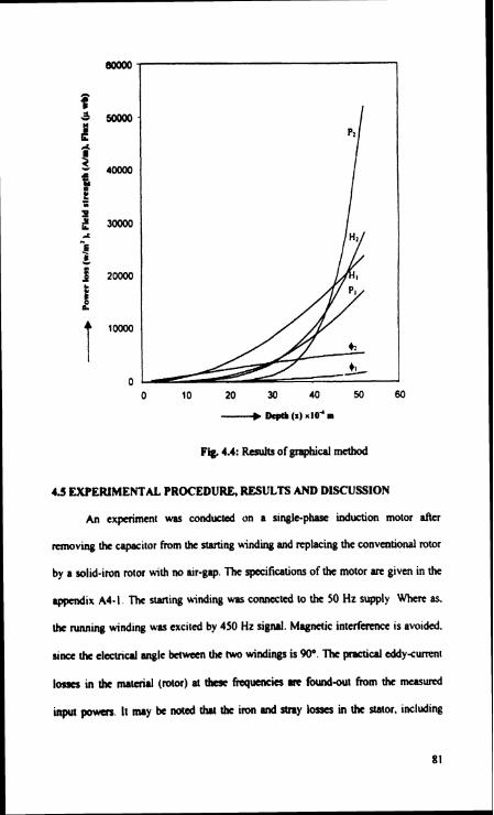
Fig. 4.4: R e d s of Braphifal mahod
4 3 EXPERIMENTAL PROCEDURE, RESULTS AND DISCUSSION
An experiment wrs conducted on a single-ph induction motor after
moving Ihe capacitor From the swing w i n d i and replacing the wnveapional rotor
by a solid-iron rotor with no air-gap. The specifications of the motor are given in the
rppmlix A4- I . The swing winding was connected lo the 50 Hz supply Where as.
h e m i n g winding was excited by 450 Hz signal. Magnetic intcrfrrrncr is avoided.
since the c l d d angle b?nvcen Ihr two windings is 909. The prrtid eddysurr~nt
loges in h e mamill (rotor) at 1&Jc fraluencies m found-out h m the measured
input p o w . Ir may k noted Iht Ihe iron and stny losses in the stator, including
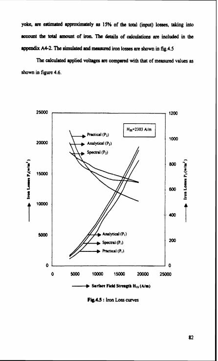
yoke, are estimmd approximately u 15% of the total ( i ) losses, talring into
lccount the toW mount of irw. lk &tails of calWons an included in the
rppcsdix A4-2. The sirnulaud d meamid iron lor#s an show in fig.4.5
The ulcuiatcd applied voltages RE compllrtd with that of meamred valucs as
shown in figure 4.6.

F i i 4.6: Applied Volges
For p r a t i n g the high frequency signal, oscillator and high capacity (80 Wans)
pow amplifier arc wed. It is taken carc that the two signals s ~ s at the same time
or in ather-words that Ihc phase-shifl is adjusted to zero. But, the phase-shift does not
have much effect on chc power losses. The reason is that, h e lnquency separation
hawem thr two signals is more. Havv thc anrage power loss ur: almost
idcpcndm of phmeshifi.
Thc infinite hdfsprc lhcory is adapted for clatrical machincs. by modifying
thr rpscifa nsislana of mtM &al so as lo incoprue the corrcclion factor for

curvature rad nd d k t a [14]. F i y , a suitable corrcdion factor is ah h q m a t d
into d v i t y to acmmt for tanpsraftue rise. Tk tbaory is provided in appdix
A4-3. Tk effective nsihvity b 1.06 x 1.77 x 1.2 x 16.58 x 10' a-m.
4.6 CONCLUSIONS
A new clusical numerical method called Pseudo-Spectrai mabod is successfully
implemented to find the field disbibution in the solid-iron mtor of induction motor,
when it is subjected to two-fresucncy excitation. It is found that b e simulated powa
loam in the mtor M agreeing with the eexperimentd values. A grapbcal metbod is
also presented to evaluate the field distribution in the specimen.
A4: APPENDIX
ACI: W i h of single-pbuc induction motor:
Rated output pomr : 1.0 )Cw
lnpn voltwe (V) : 220 volts
Effective number of turns of (starhg) winding A , @I) : 334
D.C resistance of winding A ,(RI) : 8.0 Ohms
laducuncc of wrnding A, &I) : 0.045 Henrys
Effective number of turns of (running) wiading 9. ( N 2 ) : 286
D.C resistance of winding 9, &z) : 2.5 Ohms
lndunurcc of winding 9. (L2) : 0.026 Henrys
Diamacr of mtor (D) : 0.106 rn
Length of mtor (L) : 0.109 m
Spccific misturcc of h e rotor material (b) : 16.58~10~ fl-m
B-H curve of rotor material : Figure 4.1(p72)
Length of the air-gap :Zao
End rings : Nil

AC.2 :~mmto i lpd to t8 l~LntbLnta@r
Thcl~hlduItatotm
(a) c o p p t l l o s s g i n t & ~ a n d
(b) I r o n l ~ i n t h e ~
(a) Evrlmtioa of copper lou: Kaowia$ (he nsicrance of each winding, c o p
losses aI any load can be calculated.
(b) Evnlnation of iron lou: Tbest lo- can be further classified as stator teah and
core lows. The calculations of iron losses are based on the total migbt and the flux
density in the material. The values given in the brackets M a t c l y after the
formulae arc rcfemd to the specific motor, whose details an given in the
appendix A4- I.
(i) Stator tu tb loor
T& total weight of all stator leah is given by
(wst-36*5x10" *2x10a * 0.109.7.65xld = 3Kgs)
Whm Ss- numba of stator slots
Ws, dss - width d of each stator slot, metem
LX-le@ of mor con, m a r s
&-specific weight of iron. kgfhn'
T& iron loss in the stslar tath (P,) = a*&,' *WP
(Pal= 6.5*1.5' *3 = 43.87 warns)
Where 'a' is a con sun^. la value is 6.5 for teeth and 4.7 for corc [24].

(if)Strtor are lou
The imn 1- in the stator corc me also &mated in tbc same manna ar tbat of
atator teeth loss.
Thc depth of stator corc is given by
Where D, Do arc inm and outer dinmeten of stator.
The mean diameter of stator wrc is given by
DMU = D O ~ S C
(D-f0.179-0.015 -0.164m)
H a w the weight of che stator corc is,
ww = A.D~~v.~sc .Lsc.~I
(wK= nb0.164* 0.015 *0.109 7.65xld = 6.44 kgs)
The iron loss in the stator con ( P s ) * a * b 2 *WSC
(PLw = 4.7* 1' ,644 1 30.26 W)
Thc total iron loss in rhc stator (P,) = Pia + Psc
(P, = 43.87 + 30.26 z 75 wans)
The won losses and stray losses in stator & yoke an d e n as two-times P, .
So
P - ZbP,
(P ~ 2 ~ 7 5 = 150 watts)

Tbdixe, fortlib Mehhretbetacal iron loucg an the ator side, includiislmy
IoMcSrre ISHof~inpttpoWer.
A C J : T b e ~ 1 h c t o n k r a m h m u d e 8 d c d k c t l [ 1 4 ]
(a) Clll'V8hm
When M infinite half- hwy is applii to r cylindrical coordinate
system, it bccomcs neceJsuy to makc an allowanx fot the curvature to confirm the
physical fact that actual c u m n ~ is reduced. This reduction in- depends upon the
depth of pmetntion. Thc redudion htor given in the reference is (D-2xlTJyD.
W k D is the dimera of the mtor, and xl is the depth of perneation of signal
which goes dapcr thrn Mothn signal. In this use it is the depth of pcmtration of
low frrqwncy signal. For the given surface excitation of the rotor, the stator cumnt is
reduced by the above factor i.e (D2x113)lD. In effect, the d o of transformation is
inuaKd by Ihe ~une h o t . Hence, an alkmmcc for the c u w ~ can be made by
~ncrusing the specific resistance by a hem,
Whcrc the valuc of x, is daenincd using the equation (3.25) for the maximum valuc
0 f I i 1 ~

@)Corrrtb.Cordrlkeb
In the intinite Wf-spueImrlyris, ilhskenlPsMItdthtalltheoumatsin
the rotor flow axially. In other words. ti^^ end e t W s have been ignored. It is obvious
that the end effects would kpend on the physical d i i i o n s o f the mtor, the type of
md- rings used, no end-rings used Md the rotor frequency. An empirical comction
for these cffeas is to modify the specific resistance of the rotor by r factor
When K=l. for the rotor with c~pper end rings.
K = (lhk), for the mtor with steel end rings.
K = 1.77(1+0.49S) with no end-rings,
S. L and t arc slip, rotor active length and pok pitch mpcctivcly.
KZ =K (Since S=O. UIC slip not come into picture as then is no revolving
magnetic field)
So K251.77
(c) Corrcrtk. tor b m p m h n rbe
To consider Ihc cffccl of incrrut in lanpm~c on che resistivity o f dK
mucrd. M appropriate multi f i ion frcm is manned as KJ = 1.2.
To wmmuizc. the effective ooncdion lrctw is K K I K ~ K l = I .06* 1.77*1.2 = 2.25
flmtfore, the m o d i f i nsiwvity is p *p, *~=16.58*10~*2.25 =37.33*14'0hm-m.


