Hierarchical Variable Fidelity Methods for Rotorcraft Aerodynamic Design and Analysis Eliot W. Quon Marilyn J. Smith Daniel Guggenheim School of Aerospace Engineering Georgia Institute of Technology Atlanta, Georgia 30332 Glen R. Whitehouse Daniel A. Wachspress Continuum Dynamics, Inc. Ewing, New Jersey, 08618 A coupling framework has been developed for unstructured computational fluid dynamics (CFD) solvers to allow for simple activation of a variety of wake solvers. In addition, the interface has been parallelized and extended to support dynamic, overset meshes in rotating frames. Wake capture and performance calculations demonstrate the validity of the framework. Demonstration cases include an oscillating wing, the hovering Caradonna-Tung rotor and ROBIN rotor-fuselage interaction for mul- tiple coupling variations between CHARM, VorTran-M, and FUN3D. These results illustrate that the hybrid methods can provide more accurate results with reduced grid sizes for various applications. The modification of only one solver at each incremental level of analysis permits the user to identify the source of changes in solution results. Background Lifting bodies produce wakes that interact with other bod- ies immersed in the same fluid. In particular for rotorcraft, the problem becomes significantly more complicated since the rotor wake remains near the vehicle in hover, ascent and low-speed forward flight. The proximity of the wake in- creases induced inflow and reduces helicopter thrust. More- over, since the main rotor wake may impinge on the fuse- lage, such interactions are an important consideration in modern rotorcraft design. For example, empennage im- pingement may result in undesirable handling qualities such as low-speed pitch up and tail buffet. Moreover, the wake can also generate unsteady impulsive loads on the fuselage, resulting in vibrations, thus negatively impacting the crew and passenger flight experience. Given the complexity of rotorcraft interactional aerodynamics problem, it is com- mon for tail and empennage designs to be modified signifi- cantly after first flight (Ref. 1). Development of many aerospace technologies, not lim- ited to helicopter rotor-fuselage applications, requires ac- curate resolution of both near- and far-field flow phenom- ena. In rotorcraft, far-field resolution is especially impor- tant due to the persistence of wakes for long periods of Presented at the American Helicopter Society 67th Annual Forum, Virginia Beach, VA, May 3-5, 2011. Copyright c 2011 by the American Helicopter Society International, Inc. All rights reserved. time. However, numerical predictions involve a trade-off between accuracy, turn-around time and computational ex- pense (Ref. 2). Current grid-based CFD codes can theoreti- cally model the entire flow field, but resolution and preser- vation of wake features becomes difficult since typical grid sizes used in industrial simulations are susceptible to nu- merical dissipation. The artificial diffusion of vorticity that results can be mitigated using grid adaptation techniques and higher-order methods (Refs. 2–4), but this may not be practical for all applications since computational cost in- creases significantly. For this reason, computationally ef- ficient hybrid methods may be more attractive, especially during design and for flight test support. Traditional Lagrangian free wake methods are inexpen- sive, but become less accurate when vortex elements in the wake become distorted and tangled due to interactions with other vortices and solid bodies (i.e. rotor blades and the fuselage) (Ref. 5). These interactions typically occur in the rotor near field (e.g. BVI), which motivates coupling to a CFD solver to resolve the highly viscous and possibly compressible flow near the rotor. In such an approach, the CFD code does not have to resolve the entire wake region, thus the size of the CFD domain can be greatly reduced and computational efficiency maximized. Several hybrid CFD/free-wake methods have been previously developed; however, while predictions of the normal forces have been generally improved, pitching moments have been less well captured (Ref. 6). Additional challenges associated with
Transcript
Hierarchical Variable Fidelity Methods for Rotorcraft Aerodynamic Designand Analysis
Eliot W. Quon Marilyn J. SmithDaniel Guggenheim School of Aerospace Engineering
Georgia Institute of TechnologyAtlanta, Georgia 30332
Glen R. Whitehouse Daniel A. WachspressContinuum Dynamics, Inc.Ewing, New Jersey, 08618
A coupling framework has been developed for unstructured computational fluid dynamics (CFD)solvers to allow for simple activation of a variety of wake solvers. In addition, the interface has beenparallelized and extended to support dynamic, overset meshes in rotating frames. Wake capture andperformance calculations demonstrate the validity of the framework. Demonstration cases include anoscillating wing, the hovering Caradonna-Tung rotor and ROBIN rotor-fuselage interaction for mul-tiple coupling variations between CHARM, VorTran-M, and FUN3D. These results illustrate that thehybrid methods can provide more accurate results with reduced grid sizes for various applications.The modification of only one solver at each incremental level of analysis permits the user to identifythe source of changes in solution results.
Background
Lifting bodies produce wakes that interact with other bod-ies immersed in the same fluid. In particular for rotorcraft,the problem becomes significantly more complicated sincethe rotor wake remains near the vehicle in hover, ascent andlow-speed forward flight. The proximity of the wake in-creases induced inflow and reduces helicopter thrust. More-over, since the main rotor wake may impinge on the fuse-lage, such interactions are an important consideration inmodern rotorcraft design. For example, empennage im-pingement may result in undesirable handling qualities suchas low-speed pitch up and tail buffet. Moreover, the wakecan also generate unsteady impulsive loads on the fuselage,resulting in vibrations, thus negatively impacting the crewand passenger flight experience. Given the complexity ofrotorcraft interactional aerodynamics problem, it is com-mon for tail and empennage designs to be modified signifi-cantly after first flight (Ref. 1).
Development of many aerospace technologies, not lim-ited to helicopter rotor-fuselage applications, requires ac-curate resolution of both near- and far-field flow phenom-ena. In rotorcraft, far-field resolution is especially impor-tant due to the persistence of wakes for long periods of
time. However, numerical predictions involve a trade-offbetween accuracy, turn-around time and computational ex-pense (Ref. 2). Current grid-based CFD codes can theoreti-cally model the entire flow field, but resolution and preser-vation of wake features becomes difficult since typical gridsizes used in industrial simulations are susceptible to nu-merical dissipation. The artificial diffusion of vorticity thatresults can be mitigated using grid adaptation techniquesand higher-order methods (Refs. 2–4), but this may not bepractical for all applications since computational cost in-creases significantly. For this reason, computationally ef-ficient hybrid methods may be more attractive, especiallyduring design and for flight test support.
Traditional Lagrangian free wake methods are inexpen-sive, but become less accurate when vortex elements in thewake become distorted and tangled due to interactions withother vortices and solid bodies (i.e. rotor blades and thefuselage) (Ref. 5). These interactions typically occur inthe rotor near field (e.g. BVI), which motivates couplingto a CFD solver to resolve the highly viscous and possiblycompressible flow near the rotor. In such an approach, theCFD code does not have to resolve the entire wake region,thus the size of the CFD domain can be greatly reducedand computational efficiency maximized. Several hybridCFD/free-wake methods have been previously developed;however, while predictions of the normal forces have beengenerally improved, pitching moments have been less wellcaptured (Ref. 6). Additional challenges associated with
surface interactions arise when modeling problems such asship-wake interactions and vehicle-ground interactions. Us-ing a vorticity-velocity CFD solver to evolve the wake di-rectly addresses many of these issues, though at increasedcomputational cost. Nevertheless, in order to obtain the bestwake representation, it is essential to capture the effects ofviscosity and compressibility in the rotor near field using aconventional CFD approach. As with a free-wake coupledmethodology, the physical extent of the CFD domain can beminimized, thus reducing the overall cost when comparedto pure CFD calculations (Ref. 5).
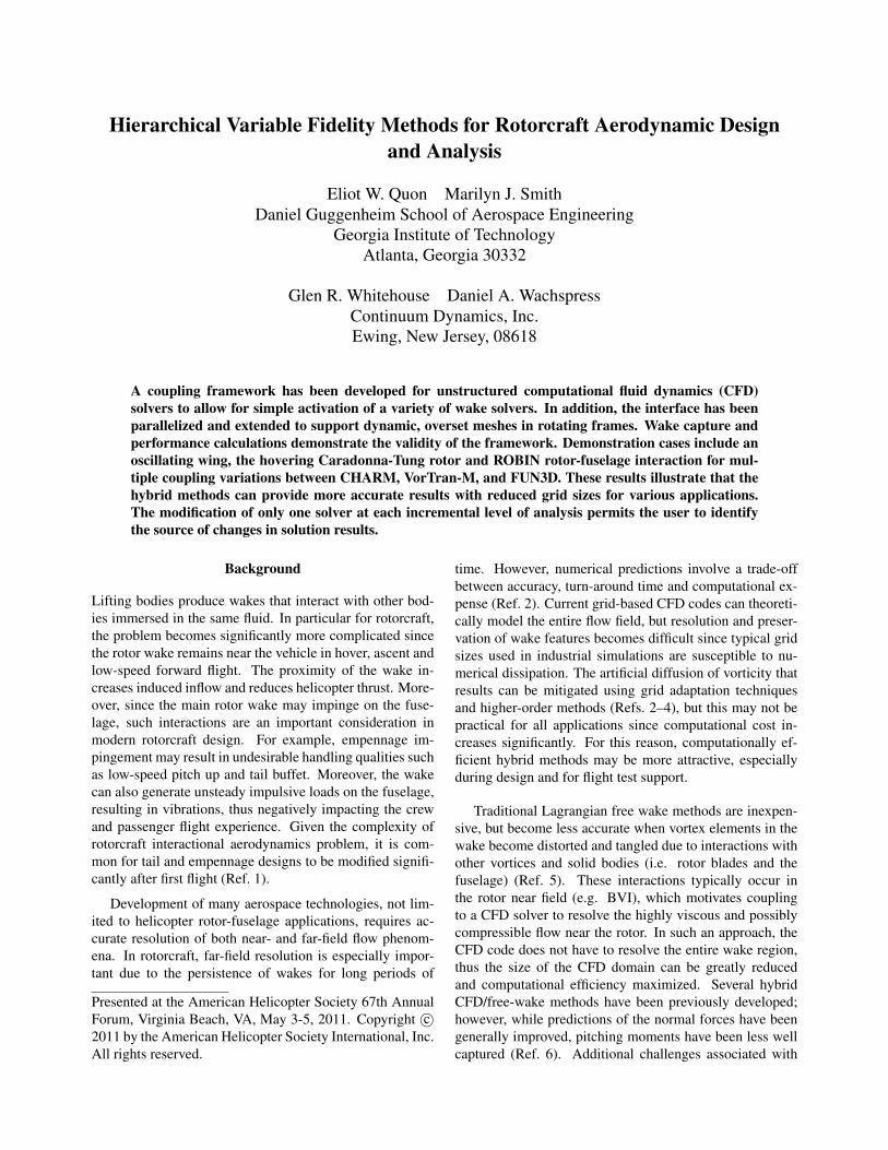
The ability to interchange one component of the near-or far-field simulation model, while maintaining the othercomponents lends itself to the ability to consistently assessthe simulation quality at different levels of fidelity. Thus,a collection of computational methods in a single frame-work allows for straightforward variation from initial de-sign to detailed analysis at decreased time and cost, as il-lustrated in Fig. 1. This paper presents such a hierarchyof CFD-based hybrid methods, comprising an aerodynam-ics module derived from a comprehensive rotorcraft analy-sis code (Ref. 7), a vorticity-velocity CFD solver (Ref. 8)and a primitive-variable RANS CFD approach (Ref. 9).Validation of the hybrid methods (FUN3D/CHARM andFUN3D/VorTran-M) are shown, along with two rotorcraftapplications of interest: a rotor in hover and rotor-fuselageinteractions.
Fig. 1: Combinations of three different codes for increasinglevels of fidelity.
Computational Methodologies
Continuum Dynamics Inc.’s (CDI) comprehensive rotor-craft code, CHARM, has been used successfully to modelrotorcraft airloads and BVI noise (Ref. 10). CHARM isequipped with lifting surface blade aerodynamics and a full-span free-vortex wake model, and uses no empirical pa-rameters to model the roll-up of the wake sheet into con-centrated vortices. The free wake model does not dissi-pate vorticity and offers real-time turnaround (Ref. 7). Sur-face pressures can be determined with an integrated panelmethod (Ref. 11).
A higher fidelity wake solution can be obtained usingCDI’s VorTran-M module. VorTran-M solves the incom-pressible Navier-Stokes equations in vorticity-velocity form
on an adaptive Cartesian grid. This approach, which ex-plicitly conserves vorticity, has been effective at predictingrotor wakes over many revolutions when coupled to a va-riety of near-body solvers (Ref. 8). Recently, VorTran-Mhas been coupled to several Cartesian, structured, and un-structured CFD codes (Ref. 5), including the solver demon-strated in this effort.
The CFD code chosen to demonstrate the coupling isFUN3D (Ref. 9), a fully unstructured Navier-Stokes RANSsolver developed primarily by researchers at NASA LaRCand Georgia Institute of Technology. This code has oversetand adaptive mesh capabilities to enable accurate resolu-tion of multiple frames of motion, making it suitable forrotorcraft analysis. In addition, FUN3D include a num-ber of source-based rotor models, including actuator blades(Refs. 12, 13), which are a viable alternative to lifting sur-face aerodynamics. Actuator blades can provide geometricdegrees of freedom along the chord and radius, and it canmodel model non-linear twist distributions. Moreover, theactuator sources provide additional flexibility in modelingthe pressure jump across the rotor at negligible cost com-pared to full-blade CFD.
An interface between FUN3D and CHARM or VorTran-M has been developed to perform fully-coupled time-accurate calculations. The FUN3D near-body solution isused to determine the local flow field at each time step,which is inserted into the VorTran-M domain as velocityat the cell corners of appropriate VorTran-M cells. Alterna-tively, an equivalent blade loading or bound vortex can bedetermined for the CHARM module to update the strengthof vortex filaments. After the wake solution is advanced,induced velocities are calculated and their influence is im-posed on the outer boundary of the FUN3D domain througha modified far-field boundary condition. The FUN3D solu-tion is then advanced to the next time step and the couplingcycle repeats.
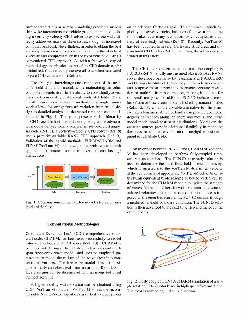
Fig. 2: Fully coupled FUN3D/CHARM simulation of a sin-gle rotating UH-60 rotor blade in high-speed forward flight.The rotor is advancing in the +x direction.
Background grid Fully coupled w/ VorTran-M Total # of Cells CL Error (%)none no 270k 0.7732 7.9
farfield→ 5c no 4.4M 0.7616 6.3none yes 420k 0.7326 2.2
- - - 0.7166 0.0
Table 1: FUN3D predicted lift for NACA0012 wing at α = 8◦, compared with experimental data from (Ref. 14).
Hybrid Methodology Validation
FUN3D + CHARM
The FUN3D/CHARM coupling interface was developedspecifically for rotorcraft applications. To validate the cou-pling, a case similar to the UH-60 8534 case (high-speedforward flight, µ = 0.368) was run using a single rotorblade in FUN3D. Blade loadings were passed from FUN3Dto CHARM, and induced velocities passed from CHARMto FUN3D. Roll-up of the CHARM vortex trailers was ob-served in the wake (Fig. 2), where vortex strengths werecalculated from the FUN3D blade loadings.
FUN3D + VorTran-M
To validate the FUN3D coupling with VorTran-M, basic testcases with a NACA0012 wing and finite cylinder (with as-pect ratios of 8.8 and 4.0, respectively) were run in a non-rotating frame. Using a free stream Mach number of 0.2and the incompressible path within FUN3D, the wing wassimulated at 8◦ angle of attack. A 240,000 node tetrahedralmesh that extended one chord length beyond the wing in alldirections was used for these simulations. To provide datafor correlation, the two-dimensional lift curve slope (a2D)from Abbott and von Doenhoff (Ref. 14) (6.3025/rad) wasmodified to account for three-dimensional effects using thewell-known aspect ratio correction (Ref. 15). Table 1 il-lustrates that a notable improvement in the predicted lift isobserved when coupled to VorTran-M, using an order ofmagnitude fewer cells than the FUN3D simulation alone.
A dynamic case was then evaluated with the wing pitch-ing at 8±5◦ at a reduced frequency of k = ωc/2U∞ = 0.5.The run successfully demonstrates dynamic update of theoverset insertion region in which the flow field is passedfrom FUN3D to VorTran-M (Fig. 3). The VorTran-M do-main is dynamically resized to encompass the convectedvorticity that remains purely outside the FUN3D domain.Again, preservation of shed vorticity including the start-ing vortex was observed. In addition, the correspondingVorTran-M solution shows three-dimensional wake devel-opment (Fig. 4). In particular, the pitching moment showsexcellent correlation, matching both magnitude and phase,while the lift shows a slight magnitude reduction and phasedelay due to the increased wake influence.
The classical problem of a circular cylinder in a cross-flow was evaluated both in terms of predicted Strouhal num-ber and the wake structure. A free stream Mach numberof 0.2 with a Reynolds number of 3900 was investigated.The fully tetrahedral grid consisted of 3 million nodes,which is larger than the prior grids, but which acted as averification of the capability of the parallel hybrid com-putations. It should be noted that Lynch (Ref. 12) foundthat the tetrahedral grid was not the best for this problem;a mixed-element mesh with specified boundary layer as-pect ratio cell sizes and growth was required to capturethe most accurate surface characteristics. The FUN3D-alone grid spanned 19.5 diameters downstream, while thenear-body FUN3D/VorTran-M grid spanned 3.5 diametersin the wake. The predicted primary Strouhal number forthe FUN3D/VorTran-M simulation was extracted at themidspan and computed to be 0.20, matching the experimen-tal and FUN3D simulation predictions (Ref. 12) on the fullgrid. When running the near-body grid with coupling, sig-nificant three-dimensional flows are observed (Fig. 5), as isexpected from the configuration.
Accuracy of Wake Geometry for a Rotor in Hover
The two-bladed hovering rotor of Caradonna and Tung(Refs. 16, 17) provides an excellent correlation case withwhich to evaluate the FUN3D/VorTran-M methodology.The experiments included numerous blade pressure and tipvortex geometry measurements, and have shown that boththe blade loadings and vortex trajectories are relatively in-sensitive to rotor tip speed (Ref. 16). For this study, therotor was run at 1250 RPM (Mtip = 0.439) with a fixed col-lective pitch of 8◦.
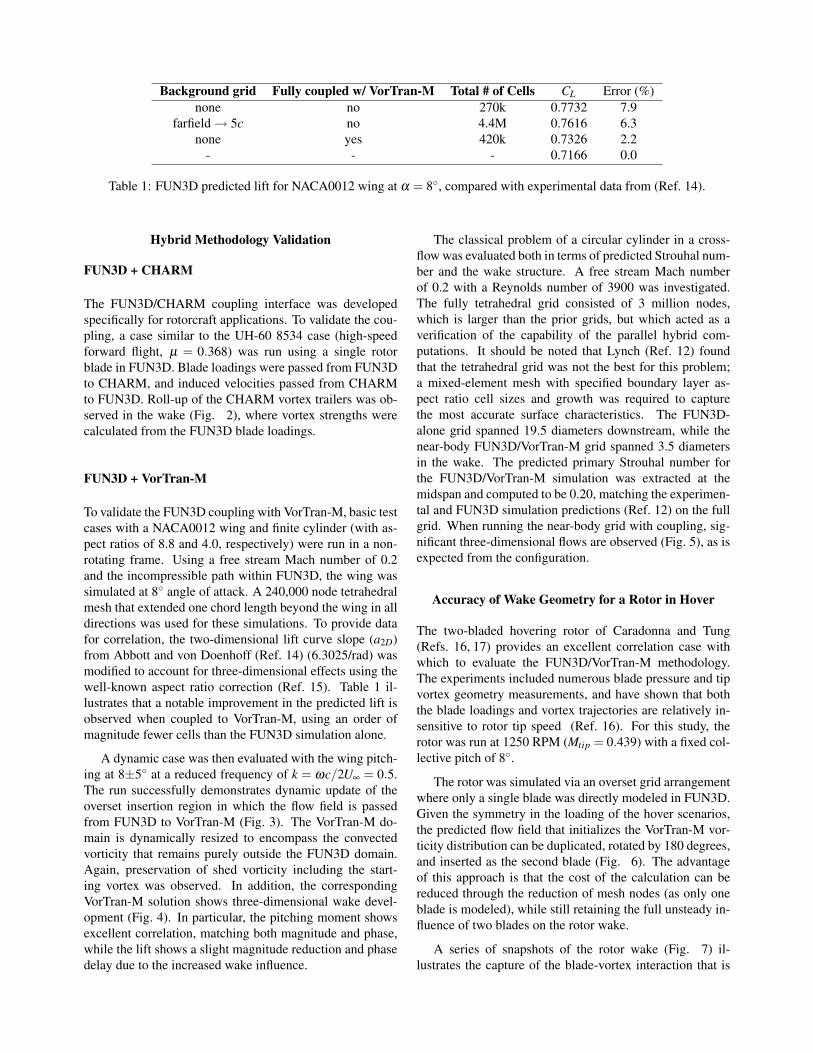
The rotor was simulated via an overset grid arrangementwhere only a single blade was directly modeled in FUN3D.Given the symmetry in the loading of the hover scenarios,the predicted flow field that initializes the VorTran-M vor-ticity distribution can be duplicated, rotated by 180 degrees,and inserted as the second blade (Fig. 6). The advantageof this approach is that the cost of the calculation can bereduced through the reduction of mesh nodes (as only oneblade is modeled), while still retaining the full unsteady in-fluence of two blades on the rotor wake.
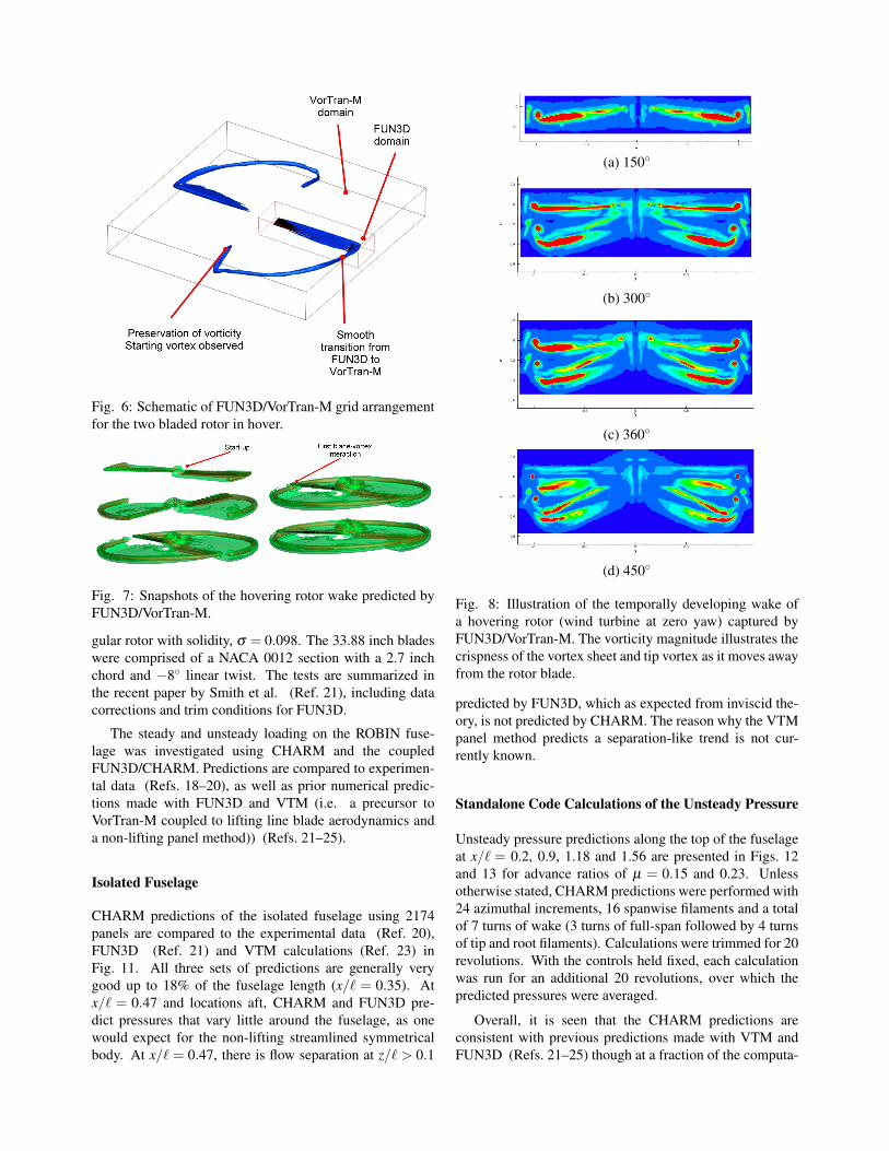
A series of snapshots of the rotor wake (Fig. 7) il-lustrates the capture of the blade-vortex interaction that is
Fig. 3: Vorticity magnitude of a pitching NACA0012 wing with FUN3D/VorTran-M coupling, showing the coupled wakeevolution after 1-4 vortex shedding cycles. The top row shows the flowfield output from FUN3D and the bottom row showsthe corresponding flowfield from VorTran-M.
Fig. 4: Iso-surfaces of vorticity magnitude for pitchingNACA0012 wing.
present, and demonstrates the build-up of the wake struc-ture as VorTran-M captures the long-age wake in hover. Thecharacteristic of the resulting flow field can be observed viavorticity in Fig. 8.
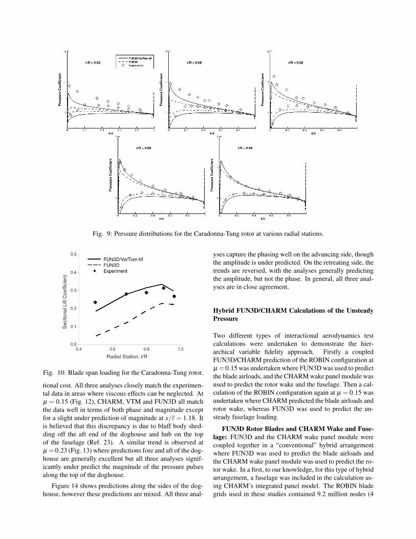
Sectional lift (averaged over one rotor partial-revolution)compares favorably with experiment (Fig. 10). In the cou-pled FUN3D/VorTran-M case the average error comparedto experiment is less than 10% and represents a drastic im-provement over the standalone FUN3D case. Lift is slightlyunder predicted on the inboard portion of the blade, as a re-sult of vortices persisting near the blade root. Similar flowfeatures were also observed in calculations using the struc-tured CFD solver, OVERFLOW (Ref. 5). Alternative tech-niques such as adaptive mesh refinement are expected toimprove the inflow prediction in this region. Correspondingpressure distributions at select radial stations are shown inFig. 9 and demonstrate the same reduction in inboard bladeloading. In all cases, the coupled result predicts pressurescloser to the experimental values. Significant improvementsare observed near the tip using FUN3D/VorTran-M cou-pling, with the experimental location and amplitude of thesuction peak being accurately captured at the two furthestoutboard stations.
The grid used in the FUN3D/VorTran-M coupling con-tained 2.2 million nodes, reduced from 5.3 million nodesin the FUN3D standalone case. Additional improvementmay be obtained with the feature-based adaptation demon-strated in Ref. 4 to focus grid nodes where they are neededfor both applications of FUN3D. It is anticipated that, in
(a) Overhead view
(b) Side view
Fig. 5: Iso-surfaces of vorticity magnitude for finite cylin-der in crossflow, with vorticity contours shown in the mid-span plane.
order for FUN3D to produce loads of the same accuracyas the coupled case, significant grid refinement in the wakeregion will be necessary, thus corresponding to increasedcomputational expense.
Rotor-Fuselage Interactions
Rotor-fuselage interactions were investigated by Mineckand coworkers at NASA Langley Research Center usinga generic fuselage configuration (the ROtor Body INterac-tion, or ROBIN, model) (Refs. 18–20). The ROBIN fuse-lage geometry is defined by a set of algebraic equations atvarious fuselage stations to yield a streamlined slender fuse-lage body and an engine mount (doghouse). Wind tunneltests were performed with and without a 4-bladed rectan-
Fig. 6: Schematic of FUN3D/VorTran-M grid arrangementfor the two bladed rotor in hover.
Fig. 7: Snapshots of the hovering rotor wake predicted byFUN3D/VorTran-M.
gular rotor with solidity, σ = 0.098. The 33.88 inch bladeswere comprised of a NACA 0012 section with a 2.7 inchchord and −8◦ linear twist. The tests are summarized inthe recent paper by Smith et al. (Ref. 21), including datacorrections and trim conditions for FUN3D.
The steady and unsteady loading on the ROBIN fuse-lage was investigated using CHARM and the coupledFUN3D/CHARM. Predictions are compared to experimen-tal data (Refs. 18–20), as well as prior numerical predic-tions made with FUN3D and VTM (i.e. a precursor toVorTran-M coupled to lifting line blade aerodynamics anda non-lifting panel method)) (Refs. 21–25).
Isolated Fuselage
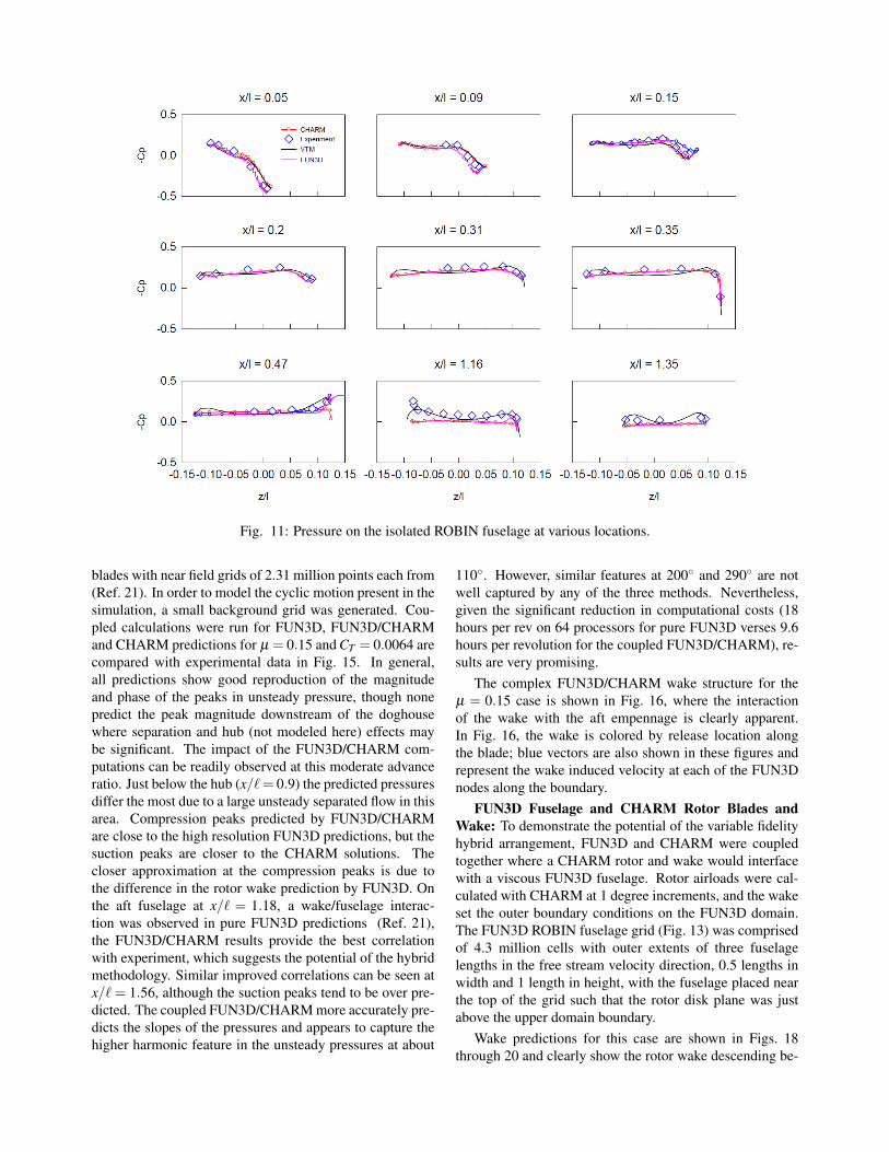
CHARM predictions of the isolated fuselage using 2174panels are compared to the experimental data (Ref. 20),FUN3D (Ref. 21) and VTM calculations (Ref. 23) inFig. 11. All three sets of predictions are generally verygood up to 18% of the fuselage length (x/` = 0.35). Atx/` = 0.47 and locations aft, CHARM and FUN3D pre-dict pressures that vary little around the fuselage, as onewould expect for the non-lifting streamlined symmetricalbody. At x/` = 0.47, there is flow separation at z/` > 0.1
(a) 150◦
(b) 300◦
(c) 360◦
(d) 450◦
Fig. 8: Illustration of the temporally developing wake ofa hovering rotor (wind turbine at zero yaw) captured byFUN3D/VorTran-M. The vorticity magnitude illustrates thecrispness of the vortex sheet and tip vortex as it moves awayfrom the rotor blade.
predicted by FUN3D, which as expected from inviscid the-ory, is not predicted by CHARM. The reason why the VTMpanel method predicts a separation-like trend is not cur-rently known.
Standalone Code Calculations of the Unsteady Pressure
Unsteady pressure predictions along the top of the fuselageat x/` = 0.2, 0.9, 1.18 and 1.56 are presented in Figs. 12and 13 for advance ratios of µ = 0.15 and 0.23. Unlessotherwise stated, CHARM predictions were performed with24 azimuthal increments, 16 spanwise filaments and a totalof 7 turns of wake (3 turns of full-span followed by 4 turnsof tip and root filaments). Calculations were trimmed for 20revolutions. With the controls held fixed, each calculationwas run for an additional 20 revolutions, over which thepredicted pressures were averaged.
Overall, it is seen that the CHARM predictions areconsistent with previous predictions made with VTM andFUN3D (Refs. 21–25) though at a fraction of the computa-
Fig. 9: Pressure distributions for the Caradonna-Tung rotor at various radial stations.
Fig. 10: Blade span loading for the Caradonna-Tung rotor.
tional cost. All three analyses closely match the experimen-tal data in areas where viscous effects can be neglected. Atµ = 0.15 (Fig. 12), CHARM, VTM and FUN3D all matchthe data well in terms of both phase and magnitude exceptfor a slight under prediction of magnitude at x/` = 1.18. Itis believed that this discrepancy is due to bluff body shed-ding off the aft end of the doghouse and hub on the topof the fuselage (Ref. 23). A similar trend is observed atµ = 0.23 (Fig. 13) where predictions fore and aft of the dog-house are generally excellent but all three analyses signif-icantly under predict the magnitude of the pressure pulsesalong the top of the doghouse.
Figure 14 shows predictions along the sides of the dog-house, however these predictions are mixed. All three anal-
yses capture the phasing well on the advancing side, thoughthe amplitude is under predicted. On the retreating side, thetrends are reversed, with the analyses generally predictingthe amplitude, but not the phase. In general, all three anal-yses are in close agreement.
Hybrid FUN3D/CHARM Calculations of the UnsteadyPressure
Two different types of interactional aerodynamics testcalculations were undertaken to demonstrate the hier-archical variable fidelity approach. Firstly a coupledFUN3D/CHARM prediction of the ROBIN configuration atµ = 0.15 was undertaken where FUN3D was used to predictthe blade airloads, and the CHARM wake panel module wasused to predict the rotor wake and the fuselage. Then a cal-culation of the ROBIN configuration again at µ = 0.15 wasundertaken where CHARM predicted the blade airloads androtor wake, whereas FUN3D was used to predict the un-steady fuselage loading.
FUN3D Rotor Blades and CHARM Wake and Fuse-lage: FUN3D and the CHARM wake panel module werecoupled together in a “conventional” hybrid arrangementwhere FUN3D was used to predict the blade airloads andthe CHARM wake panel module was used to predict the ro-tor wake. In a first, to our knowledge, for this type of hybridarrangement, a fuselage was included in the calculation us-ing CHARM’s integrated panel model. The ROBIN bladegrids used in these studies contained 9.2 million nodes (4
Fig. 11: Pressure on the isolated ROBIN fuselage at various locations.
blades with near field grids of 2.31 million points each from(Ref. 21). In order to model the cyclic motion present in thesimulation, a small background grid was generated. Cou-pled calculations were run for FUN3D, FUN3D/CHARMand CHARM predictions for µ = 0.15 and CT = 0.0064 arecompared with experimental data in Fig. 15. In general,all predictions show good reproduction of the magnitudeand phase of the peaks in unsteady pressure, though nonepredict the peak magnitude downstream of the doghousewhere separation and hub (not modeled here) effects maybe significant. The impact of the FUN3D/CHARM com-putations can be readily observed at this moderate advanceratio. Just below the hub (x/` = 0.9) the predicted pressuresdiffer the most due to a large unsteady separated flow in thisarea. Compression peaks predicted by FUN3D/CHARMare close to the high resolution FUN3D predictions, but thesuction peaks are closer to the CHARM solutions. Thecloser approximation at the compression peaks is due tothe difference in the rotor wake prediction by FUN3D. Onthe aft fuselage at x/` = 1.18, a wake/fuselage interac-tion was observed in pure FUN3D predictions (Ref. 21),the FUN3D/CHARM results provide the best correlationwith experiment, which suggests the potential of the hybridmethodology. Similar improved correlations can be seen atx/` = 1.56, although the suction peaks tend to be over pre-dicted. The coupled FUN3D/CHARM more accurately pre-dicts the slopes of the pressures and appears to capture thehigher harmonic feature in the unsteady pressures at about
110◦. However, similar features at 200◦ and 290◦ are notwell captured by any of the three methods. Nevertheless,given the significant reduction in computational costs (18hours per rev on 64 processors for pure FUN3D verses 9.6hours per revolution for the coupled FUN3D/CHARM), re-sults are very promising.
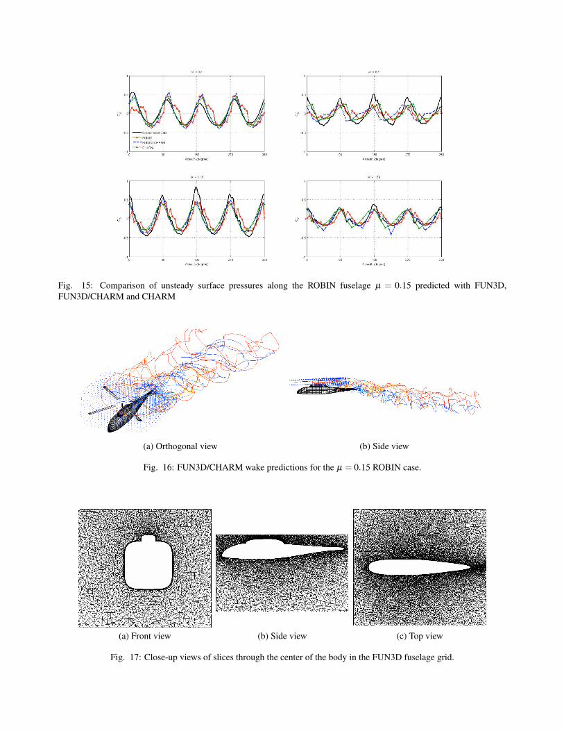
The complex FUN3D/CHARM wake structure for theµ = 0.15 case is shown in Fig. 16, where the interactionof the wake with the aft empennage is clearly apparent.In Fig. 16, the wake is colored by release location alongthe blade; blue vectors are also shown in these figures andrepresent the wake induced velocity at each of the FUN3Dnodes along the boundary.
FUN3D Fuselage and CHARM Rotor Blades andWake: To demonstrate the potential of the variable fidelityhybrid arrangement, FUN3D and CHARM were coupledtogether where a CHARM rotor and wake would interfacewith a viscous FUN3D fuselage. Rotor airloads were cal-culated with CHARM at 1 degree increments, and the wakeset the outer boundary conditions on the FUN3D domain.The FUN3D ROBIN fuselage grid (Fig. 13) was comprisedof 4.3 million cells with outer extents of three fuselagelengths in the free stream velocity direction, 0.5 lengths inwidth and 1 length in height, with the fuselage placed nearthe top of the grid such that the rotor disk plane was justabove the upper domain boundary.
Wake predictions for this case are shown in Figs. 18through 20 and clearly show the rotor wake descending be-
Fig. 12: Unsteady pressure at various points along the top centerline of the fuselage (µ = 0.15, CT = 0.0064).
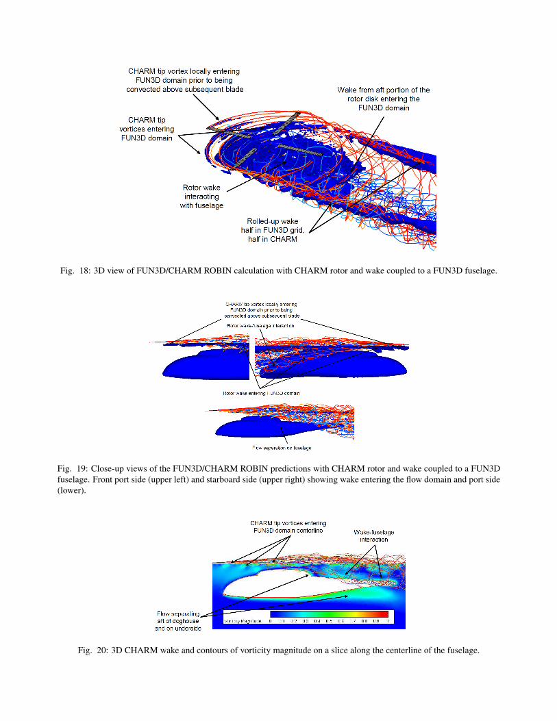
low the rotor disk plane and entering FUN3D prior to im-pacting the aft fuselage. Complicated roll-up dynamics areobserved near to the leading edge of the rotor in Figs. 18and 19 where the tip vortices descend below the rotor diskand enter the FUN3D domain, prior to completing roll-upand convecting upwards to pass over the advancing blade.Aft of the rotor disk, the wake from each blade rolls up toform the super-vortices, as illustrated in Fig. 18. On theretreating side of the rotor these vortices pass along theupper boundary of the FUN3D domain, with half of thestructure inside FUN3D and half being represented solelyby CHARM. On the advancing side of the rotor, the super-vortices enter the FUN3D domain and pass close to the trail-ing edge of the fuselage (Fig. 19). Figure 20 shows a con-tour plot of vorticity magnitude along the centerline of thefuselage, along with the 3D CHARM wake for clarification.The smooth transition of tip vortices into the FUN3D gridis clearly evident, particularly upstream of the hub. Aft ofthe hub, complicated wake interactions take place where theinboard rotor wake impacts the rear of the fuselage.
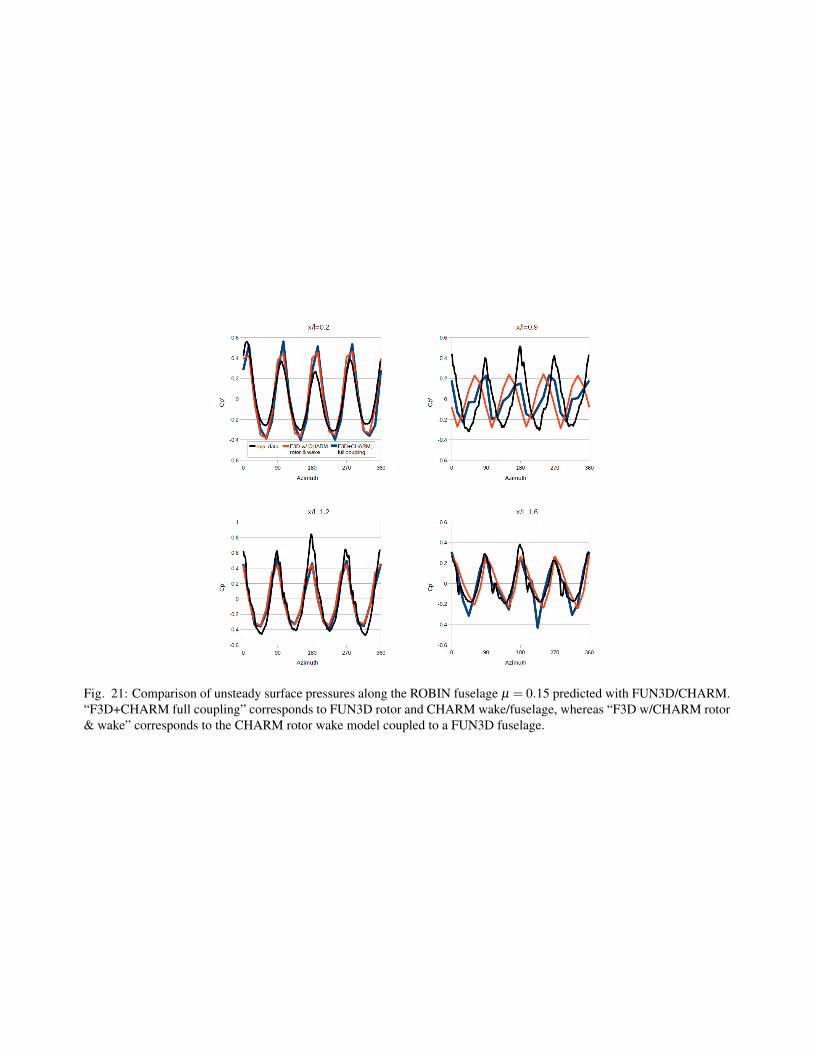
Unsteady pressures along the centerline of the upperfuselage are plotted in Fig. 21. In general, the magnitude ofthe pressure peaks is similar to the FUN3D/CHARM cal-culation with the CHARM fuselage; however, the negativepeaks at 45◦ and 225◦ at x/` = 1.6 are better captured. Atx/` = 0.9 the pressure peaks are shifted by approximately45◦ from the experiment and previous predictions, and thismay be caused, at least in part, by the flow separation on theport side of the fuselage shown in Figs. 19 and 20.
These results were obtained with over an order of magni-tude reduction in computational costs (CHARM rotor/wakeand FUN3D fuselage took 1.5 hours per revolution on 64processors; FUN3D rotor and CHARM wake/fuselage took9.6 hours per revolution; and the pure FUN3D solution took18 hours per revolution) when compared to pure FUN3D.
Conclusions
This paper describes the preliminary development of aCFD-based hierarchical framework of analysis tools suit-able for application to the entire rotorcraft design andanalysis process. This suite of tools is based around theFUN3D unstructured RANS solver (though it could beimplemented in other solvers as required) and featuresthe CHARM blade-aero/free-wake/panel module and theVorTran-M CFD wake solver. Results are presented fora variety of relevant problems, included the first presenta-tion, to the authors’ knowledge, of hybrid CFD-based pre-dictions of rotor-fuselage interactions. Predictions demon-strate improvements in loading predictions, as well as sig-nificant reductions in computational time.
Acknowledgments
This work was supported by Navy STTR contract N68335-09-C-0335 with guidance from technical monitors JenniferAbras and Mark Silva and in part by US DOE STTR DE-SC0004403.
Fig. 13: Unsteady pressure at various points along the top centerline of the fuselage (µ = 0.23, CT = 0.0064).
References
1Prouty,R. W., Military Helicopter Design Technology,Krieger, Malabar, FL, 1998.
2Komerath, N., Smith, M. J., Tung, C., “A Review of Ro-tor Wake Physics and Modeling,” Journal of the AmericanHelicopter Society, to appear, 2011.
3Wissink, A., Potsdam, M., Sankaran, V., Sitaraman, J.,Yang, Z., and Mavriplis, D. J., “A Coupled Unstructured-Adaptive Cartesian CFD Approach for Hover Prediction,”66th Annual Forum of the American Helicopter Society,Phoenix, AZ, 2010.
4Shenoy, R., and Smith, M. J., “Unstructured OversetGrid Adaptation for Rotorcraft Aerodynamic Interactions,”Proceedings of the 67th Annual Forum of the American He-licopter Society, Virginia Beach, VA, May 2011.
5Whitehouse, G. R., Boschitsch, A. H., Smith, M. J.,Lynch, C. E., and Brown, R. E., “Investigation of MixedElement Hybrid Grid-Based CFD Methods for RotorcraftFlow Analysis,” 66th Annual Forum of the American Heli-copter Society, Phoenix, AZ, 2010.
7Wachspress, D. A., Keller, J. D., Quackenbush, T.R., Whitehouse, G. R., and Yu K., “High Fidelity
Rotor-Aerodynamic Module for Real-Time Flight Simula-tion”,64th Annual Forum of the American Helicopter Soci-ety, Montreal, Canada, 2008.
8Whitehouse, G. R., Boschitsch, A. H., Quackenbush, T.R., Wachspress, D. A., and Brown, R. E. , “Novel Eule-rian Vorticity Transport Wake Module for Rotrcraft FlowAnalysis,” 63rd Annual Forum of the American HelicopterSociety, Virginia Beach, VA, 2007.
9Nielsen, E. J., “Aerodynamic Design Optimization Us-ing the Navier-Stokes Equations,” 18th International Sym-posium on Mathematical Programming, Copenhagen, Den-mark, 2003.
10Wachspress, D. A., Quackenbush, T. R., and Boschitsch,A. H., “First-Principles Free-Vortex Wake Analysis for He-licopters and Tiltrotors,” 59th Annual Forum of the Ameri-can Helicopter Society, Phoenix, AZ, 2003.
11Wachspress, D. A., Quackenbush, T. R., and Boschitsch,A. H., “Rotorcraft Interactional Aerodynamics with FastVortex/Fast Panel Methods”, Journal of American Heli-copter Society, Vol. 48 (4), 2003.
12Lynch, C. E., Advanced CFD Methods for Wind Tur-bine Analysis, Ph.D. thesis, Georgia Institute of Technol-ogy, 2010.
13O’Brien, D.M., Analysis Of Computational ModelingTechniques For Complete Rotorcraft Configurations, Ph.D.thesis, Georgia Institute of Technology, 2006.
(a) Advancing side
(b) Retreating side
Fig. 14: Unsteady pressure at various points around the fuselage at lengthwise location of x/` = 0.9, on the aft portion ofthe doghouse (µ = 0.23, CT = 0.0064). VTM data not available at z/` = 0.08 on the retreating side
14Abbott, I. H. and von Doenhoff, A. E., Theory of WingSections, Dover Publications, 1959.
15Anderson, J.D., Jr., Aircraft Performance and Design,McGraw-Hill, New York, NY, Anderson, J.D., Jr., 1999.
16Caradonna, F.X. and Tung, C., “Experimental and An-alytical Studies of a Model Helicopter Rotor in Hover,”NASA-TM-81232, USAAVRADCOM TR-81-A-23, 1981.
17Caradonna, F.X. and Tung, C., “Experimental and Ana-lytical Studies of a Model Helicopter Rotor in Hover,” Ver-tica, Vol. 5, 1981, pp. 149-161.
18Elliot, J.W., Althoff, S.L., and Sailey, R.H., “InflowMeasurements Made with a Laser Velocimeter on a He-licopter Model in Forward Flight. Volume I: RectangularPlanform Blades at an Advance Ratio of 0.15,” NASA TM-100541, AVSCOM TM 88-B-004, 1988.
19Mineck, R.E. and Althoff Gorton, S.L., “Steady andPeriodic Pressure Measurements on a Generic HelicopterFuselage Model in the Presence of a Rotor,” NASA TM-2000-210286, 2000.
20Freeman, C.E. and Mineck, R.E., “Fuselage Sur-face Pressure Measurements of a Helicopter Wind-Tunnel
Model with a 3.15-Meter Diameter Single Rotor,” NASATM-80051, 1979.
21Smith, M.J., Shenoy, R., Kenyon, A.K., and Brown,R.E., “Vorticity Transport and Unstructured RANS Inves-tigation of Rotor-Fuselage Interactions,” Proceedings ofthe 35th European Rotorcraft Forum, Hamburg, Germany,September 2009.
22Kenyon, A.R. and Brown, R.E., “Wake Dynamics andRotor - Fuselage Aerodynamic Interactions,” Proceedingsof the 63rd Annual Forum of the American Helicopter So-ciety, Virginia Beach, VA, May 2007.
24Abras, J.N., Lynch, C.E., and Smith, M.J., “Advances inRotorcraft Simulations with Unstructured CFD,” Proceed-ings of the 63rd Annual Forum of the American HelicopterSociety, Virginia Beach, VA, May 2007.
25O’Brien, D.M. and Smith, M.J., “Improvements in theComputational Modeling of Rotor/Fuselage InteractionsUsing Unstructured Grids,” Proceedings of the 61st AnnualForum of the American Helicopter Society, Grapevine, TX,May 2005.
Fig. 15: Comparison of unsteady surface pressures along the ROBIN fuselage µ = 0.15 predicted with FUN3D,FUN3D/CHARM and CHARM
(a) Orthogonal view (b) Side view
Fig. 16: FUN3D/CHARM wake predictions for the µ = 0.15 ROBIN case.
(a) Front view (b) Side view (c) Top view
Fig. 17: Close-up views of slices through the center of the body in the FUN3D fuselage grid.
Fig. 18: 3D view of FUN3D/CHARM ROBIN calculation with CHARM rotor and wake coupled to a FUN3D fuselage.
Fig. 19: Close-up views of the FUN3D/CHARM ROBIN predictions with CHARM rotor and wake coupled to a FUN3Dfuselage. Front port side (upper left) and starboard side (upper right) showing wake entering the flow domain and port side(lower).
Fig. 20: 3D CHARM wake and contours of vorticity magnitude on a slice along the centerline of the fuselage.
Fig. 21: Comparison of unsteady surface pressures along the ROBIN fuselage µ = 0.15 predicted with FUN3D/CHARM.“F3D+CHARM full coupling” corresponds to FUN3D rotor and CHARM wake/fuselage, whereas “F3D w/CHARM rotor& wake” corresponds to the CHARM rotor wake model coupled to a FUN3D fuselage.