13
HOW TO USE Smith-Corona PORTABLE TYPEWRITERS FLOATING SHIFT MODELS Printed and Published by L C Smith & Corona Typewriters Inc 701 E Washington St Syracuse N Y '
HOW TO USE
Smith-CoronaPORTABLE TYPEWRITERS
FLOATING SHIFTMODELS
Printed and Published by
L C Smith & Corona Typewriters Inc701 E Washington St Syracuse N Y '

The serial number, stamped 0n the innersurface of the machine frame, right hand side,in front and a little below right ribbon spoolcup, positively identifies each individual ma-chine. Locate serial number with coverplateraised as in Fig. 10.
L C Smith 8: Corona Typewriters Inc
HOW TO USE
Smith-CoronaPORTABLE TYPEWRITERS
FLOATING SHIFTMODELS
Printed and Published by
L C Smith & Corona Typewriters Inc701 E Washington St Syracuse NY
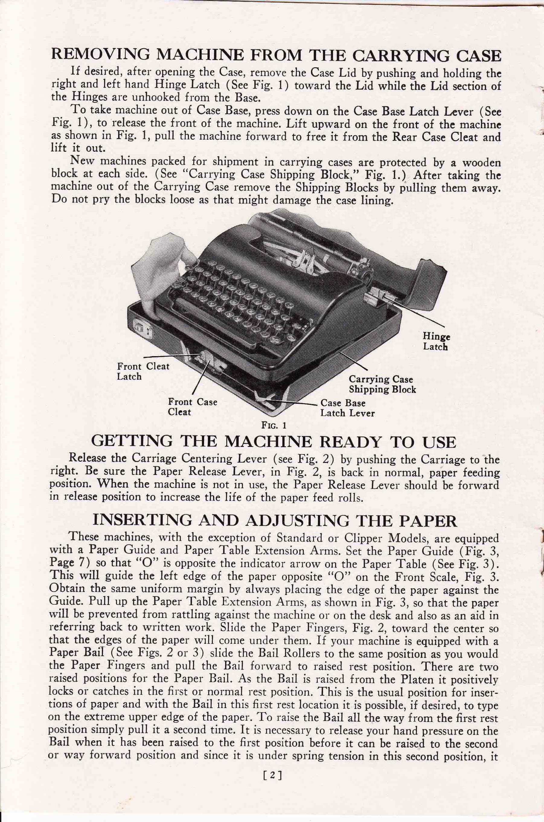
REMOVING MACHINE FROM THE CARRYING CASEIf desired, after opening the Case, remove the Case Lid by pushing and holding the
right and left hand Hinge Latch (See Fig. 1) toward the Lid while the Lid section ofthe Hinges are unhooked from the Base.
To take machine out of Case Base, press down on the Case Base Latch Lever (SeeFig. 1), to release the front of the machine. Lift upward on the front of the machineas shown in Fig. l, pull the machine forward to free it from the Rear Case Cleat andlift it out.
New machines packed for shipment in carrying cases are protected by a woodenblock at each side. (See “Carrying Case Shipping Block,” Fig. 1.) After taking themachine out of the Carrying Case remove the Shipping Blocks by pulling them away.Do not pry the blocks loose as that might damage the case lining.
a
Hinge
Front CleatLatch Carrying Case
Shipping BlockCase BaseLatch Lever
Front CaseCleat
FIG. 1
GETTING THE MACHINE READY TO USERelease the Carriage Centering Lever (see Fig. 2) by pushing the Carriage to the
right. Be sure the Paper Release Lever, in Fig. 2, is back in normal, paper feedingposition. When the machine is not in use, the Paper Release Lever should be forwardin release position to increase the life of the paper feed rolls.
INSERTING AND ADJUSTING THE PAPERThese machines, with the exception of Standard or Clipper Models, are equipped
with a Paper Guide and Paper Table Extension Arms. Set the Paper Guide (Fig. 3,Page 7) so that “O” is opposite the indicator arrow on the Paper Table (See Fig. 3).This will guide the left edge of the paper opposite “O” on the Front Scale, Fig. 3.Obtain the same uniform margin by always placing the edge of the paper against theGuide. Pull up the Paper Table Extension Arms, as shown in Fig. 3, so that the paperwill be prevented from rattling against the machine or on the desk and also as an aid inreferring back to written work. Slide the Paper Fingers, Fig. 2, toward the center sothat the edges of the paper will come under them. If your machine is equipped with aPaper BaiI (See Figs. 2 or 3) slide the Bail Rollers to the same position as you wouldthe Paper Fingers and pull the Bail forward to raised rest position. There are tworaised positions for the Paper Bail. As the Bail is raised from the Platen it positivelylocks or catches in the first or normal rest position. This is the usual position for inser-tions of paper and with the Bail in this first rest location it is possible, if desired, to typeon the extreme upper edge of the paper. To raise the Bail all the way from the first restposition simply pull it a second time. It is necessary to release your hand pressure on theBail when it has been raised to the first position before it can be raised to the secondor way forward position and since it is under spring tension in this second position, it
[2]
‘vm

must be held forward by hand. This second position of the Bail is particularly con-venient for erasing. In case of the Silent model (See Fig. 3) for the best results, the BailRollers must be equalized; i. e., both end rollers the same or an equal distance from theright and left edges of the paper and the middle roll centered. Place the paper downbehind the Platen Roller and in front of the Paper Table (See Fig. 3) as far as it willgo. Push the sheet gently down while you turn either Platen Knob, Fig. 2, in thedirection away from you, until the top edge of the paper comes up in front of the PlatenRoller. Now lower the Bail back down onto the paper.
If the paper needs straightening, pull forward on the Paper Release Lever, Fig. 2,until it catches, adjust the paper, and push the Paper Release Lever back to its normalposition. By pulling the Paper Release Lever forward you will find it easier to inserta large number of carbon copies.
VARIABLE LINE SPACERIf the writing must be on ruled lines use variable linespacing by pulling out the
Variable Linespace Knob, see Fig. 2. Then, using the platen knob, turn the paperuntil the ruled line is exactly even with the graduated edge of the line indicator (SeeFig. 2). Now push the Variable Linespace Knob in again as the Line Space Leverdoes not space up the paper when the knob is pulled out. It is best to push the variableknob in with your finger and with your thumb on the inner side of the left platen knobfor leverage.
CARRIAGE RELEASETo move the Carriage to either right or left without linespacing, writing, back-
spacing or blank spacing (using the space bar), pull either left or right hand CarriageRelease Lever (See Fig. 2) forward while controlling the Carriage with the thumb ofthe same hand. Merely release the Carriage Release Lever to locate (stop) the Carriageon the desired location.
MARGINAL RELEASESMarginal Stops and Marginal Releases are so closely related that when mentioning
one the other must also be mentioned (See “Marginal Stops”) .When the Carriage reaches the end of the line of writing (that is, when it comes
to the right Marginal Stop, Fig. 2), depressing the Marginal Release Key, Fig. 2,releases the Carriage to finish writing that line. (To complete a syllable or short word.)
If you have set the Marginal Stop for a wide left margin and should then Wish tomove the Carriage past the Stop in order to write in the left margin, depress and holdthe Marginal Release Key (See Fig. 2) while you push the Carriage to the right. Toback-space one space past the left Margin Stop, depress and hold down the MarginRelease Key while depressing the Back—Space Key (Fig. 2) . After this first back-spacing,further back—spacing can be done Without holding down the Marginal Release Key.
MARGINAL STOPSMarginal Stops make it possible to maintain a uniform left margin and end the lines
at practically the same length.To set the Stop for the left margin, move the Carriage (see “Carriage Release”) to
a point left of where you wish the line of writing to begin. Let us suppose that this isat “20” on the Front Scale, Fig. 2.
Tilt the Paper Table forward, see Fig. 2. Press down on the Button of the left handMarginal Stop, Fig. 2, and slide the Stop to 20 on the Margin Stop Rod, making surethat the left end of the Marginal Stop is seated in the groove of the Rod. The MarginalStops slide on a steel rod graduated with markings and numerals which correspond withthose on the Front Scale, Fig. 2. After so setting the left Marginal Stop you will findthat when you move the Carriage to the right it will always stop at “20” or at whateverposition you have set the Stop unless the Margin Release key is held down. After becom-ing accustomed to the machine it will prove to be a simple operation for you to set the
[3]

Marginal Stops accurately for the desired margins even at odd positions on the FrontScale and on the Margin Stop Rod.
_
Decide where you want the right margin; move the Carriage way to the right. Slidethe right Marginal Stop, Fig. 2, to the desired location on the Stop Rod. Be sure theright hand end of the right Marginal Stop is in the groove of the Margin Rod. If youset the right Stop at 70 the line locks at 69 and you must press the Margin Release keyto continue the line.
The bell will ring approximately eight spaces before the end of the line, thus indi-cating that the end of the line has nearly been reached. Machines may vary, one fromanother, but the bell on your individual machine will always ring the same numberof spaces before the end of the line.
WRITING POINTThe Writing Point is the space directly behind the center of the Type Guide,
Fig. 2. Determine the Writing Point by the space indicated thru the rectangularopening in the Guide opposite the “Pointer,” Fig. 2.
LINESPACINGTo begin another line, press against the Finger Piece of the Linespace Carriage
Return Lever, Fig. 2, giving it a smart push to the right. This not only returns theCarriage but also spaces the paper for the new line. Turning the Platen Roller, Fig.2, by means of the Platen Knobs is the easiest way to linespace and not move theCarriage. Turn the platen either by means of the Linespace Carriage Return Leveror Platen Knobs until the ratchet clicks once for each linespace desired.
Make lines either one or two spaces apart by moving the Line Space Adjuster,Fig. 2, backward or forward. When it is in the forward position, the lines will be twospaces apart. Machines may be had with “Economy” Linespacer as special equipmentwhich provides three adjustments representing 1, 1% and 2 lines.
(See the paragraph referring to the Variable Line Spacer.)
CAPITAL SHIFT KEYSThe machine in its normal position writes only the small or “Lower Case” letters.
To write capital letters or characters, the Shift Levers, Fig. 2, must be used, holdingeither one of them down while striking the key for the desired letter.
If you want to write all capitals, press down on the Shift Lock Key at the left (SeeFig. 2). The Shift Lock Key is released automatically by pressing down on the ShiftLevers.
BACK SPACERIf for any reason you want to move the carriage back (to the right) just a few
spaces, press down on the Back Space Key, Fig. 2, once for each space that you wantthe carriage to go back. Refer to the section herein, entitled, “Writing Point,” forthe method of locating desired positions or spaces for correction, and to ”NlarginalReleases” if you want to backspace past the left margin stop.
SPACE BAREach time you depress the Space Bar, Fig. 2, the Carriage moves one space to the
left, without printing. Be sure to take one stroke on the Space Bar between each word.
Hi

Margin Stop "Arrow“ Margin Stop " Arrow"
Margin Stop Button Marginal Stop ButtonPaper Bail Rollers Right Marginal Stop
Paper TableIn Forward
Tilted Position
Left Margin Stop
Paper Finger Margin St0p Rod Platen Roller
Type GuideLinespaceAdyuster Front Scale Right Carriage End
Right CarriageLeft Carriage Release LeverRelease Lever
VariableLmespaceKnob
Line Indicator
Paper ReleaseLever
Cover Plate
Tvpe Guide"7 Pointer' ‘
Manual RibbonReverse Lever
Backspacer Key
Lmespace CarriageReturn Lever"Finger Piece"
Shift Lock Shift Lever
Shift L ver Marginal Release Key9 v
Ribbon Color Indicator LeverSpace BM
Carriage Centering Lever
Fig. 2 Right Plaren Knob

RIBBON DIAL, COLOR INDICATOR LEVER ANDSTENCIL DEVICE
This device controls the printing position of the ribbon with reference to color.Setting the Color Indicator Lever (See Fig. 2) in the upper dial notch (black), eachkey stroke will print on the upper half of the ribbon. With the Lever set in the lowernotch (red), the type will strike on the bottom half of the ribbon.
When you want to cut a stencil, set the lever in the middle notch (white). Whenin this position, the type does not strike the ribbon. Be sure to set the Color IndicatorLever back to its usual position after cutting the stencil, or you will wonder why themachine does not print when used again.
Be sure to clean the type thoroughly before cutting a stencil. Use a good cleaningsolution and a brush. When brushing or wiping the type do so with a motion towardthe front and back of the machine and not sideways, as a stroke to the left and rightmay be detrimental to good alignment. Pick hardened dirt and ink from such lettersas e, g, s, 0, etc., with a common pin.
On the Silent model better stencils can be obtained if the regular “Silent” Platen isreplaced with a harder platen roll. For platen replacement, refer to InterchangeablePlaten, on Page 7.
TABULATORIf the machine is not equipped with the Tabulating mechanism, simply disregard
this reference.Depressing and holding the “Tab.” key, located at the right side of the keyboard,
causes the Carriage to move to the left. This movement of the Carriage when thetabulator key is depressed will be arrested at the various locations for which you haveset the stops, on the tabulator rack. The Tabulator Rack is the square slotted rodextending the length of the Carriage in back and is located about an inch below theMargin Stop Rod. (Margin Stop Rod is shown in Fig. 2.)
To set Tabulator Stops for ordinary correspondence on the usual business letterheadand assuming that you have already set the left Margin Stop at “10,” for a 10 spacemargin, the first Tabulator Stop should probably be set at “15,” for paragraphs indented5 spaces. Note, by the numbers of the front scale, just where you need to set TabulatorStops for the date space, company name and for the signature. These positions maycome at “30,” ”4-5” and “56” on the scale. Locate slot number “15” on the TabulatorRack. Raise the Tabulator Stop nearest the 15 slot high enough to allow sliding theStop on the Rack so that it can be pushed down into the “15” slot if chosen. If theStops have been entirely removed from the Tabulator Rack, simply push a stop downinto the “15” slot from the top surface of the Rack. In a similar manner place anotherstop in the “30” slot, a third in the “45” and the fourth in the ”56,” providing thatthese are the numbers you have chosen for your work. When placing the stops in theslots of the Tabulator Rack, be sure that they slant away from the machine and topush them way down on the Rack.
“TOUCH” SELECTORIn “Touch” Selector, our engineers have provided a simple means of altering
“Touch” Tension to suit individual styles of typing. This is as easy for the operatorto manipulate as it is to change from single to double linespacing or from black to redon the ribbon.
MOVE THE CARRIAGE TO THE EXTREME LEFT and raise theCoverplate as shown in Fig. 10.
The Touch Selector Lever and Touch Selector Dial are located directly beneaththe Coverplate at the left. (See Fig. 10.)
The Touch Selector Dial provides 7 locations for the Touch Selector Lever andthe “touch” tension on Keylevers is increased as the lever is moved from I to 7 or
[6]
from the extreme forward position to extreme rear position on the Dial. Simply pushthe Lever backward from 1 to 2, 3, 4, 5, 6 or 7, whichever seems to be the best foryour particular typing technique.
The No. 2 position is so-called “Factory Standard.” The best “Touch” for you cansoon be determined by typing with the Selector Lever in various experimental positions.
After setting the Selector Lever, close the Coverplate and be sure that it is snappedway down in latched position where it won’t rattle or be marred by the LinespaceCarriage Return Lever.
HAND-CONTROL OF RIBBON TRAVELTo always provide a fresh printing surface for the type to strike on, the ribbon
travels back and forth from one spool to the other automatically without attention.It may be desired to control the travel of the ribbon by hand, as when changing theribbon, etc., which may be done by pressing forward the Manual Reverse Lever (SeeFig. 2). The Manual Reverse Lever is under spring tension and when it is pulledforward to change the direction of the ribbon feed, it will spring back up to normalposition.
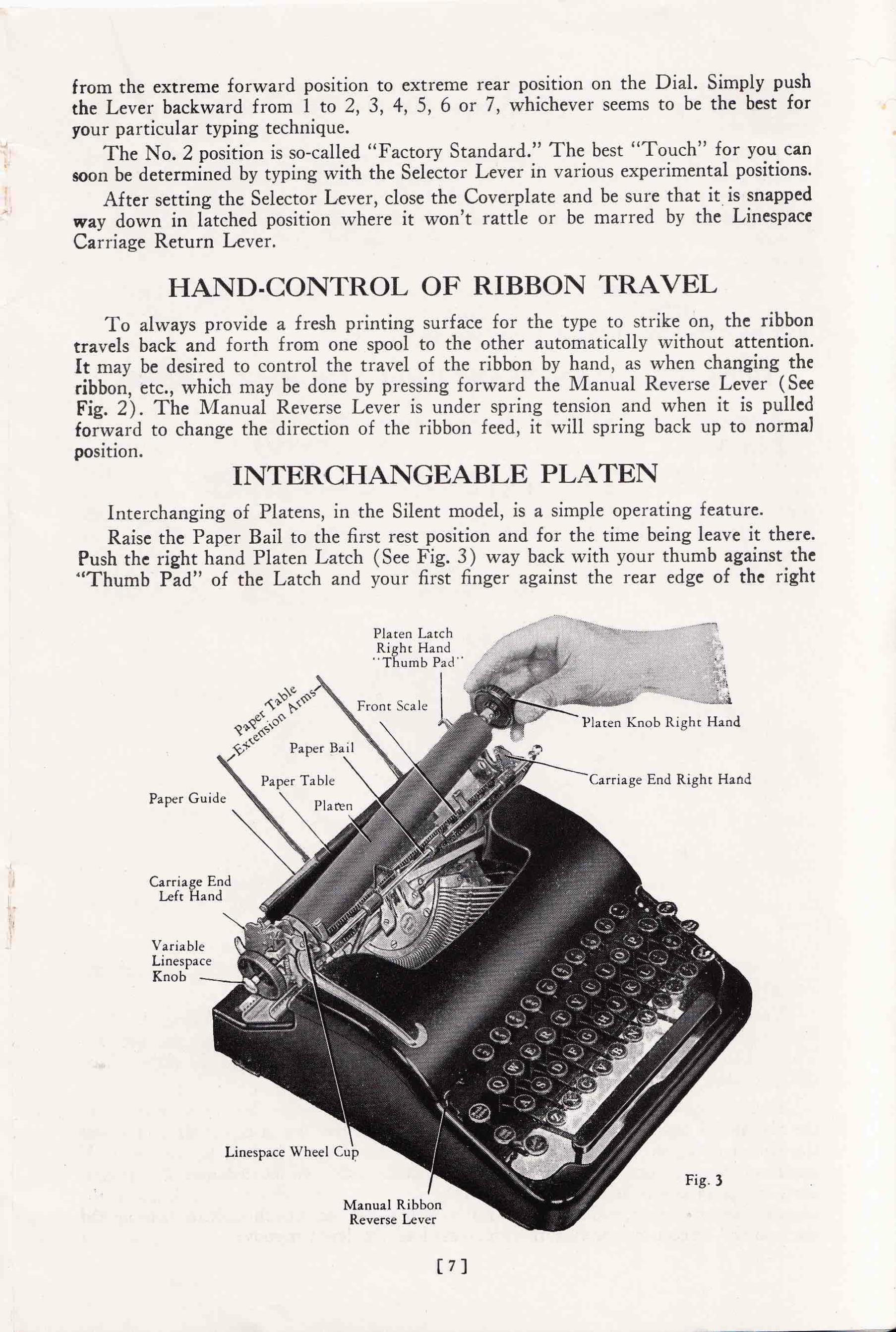
INTERCHANGEABLE PLATENInterchanging of Platens, in the Silent model, is a simple operating feature.Raise the Paper Bail to the first rest position and for the time being leave it there.
Push the right hand Platen Latch (See Fig. 3) way back with your thumb against the“Thumb Pad” of the Latch and your first finger against the rear edge of the right
Platen LatchRight Hand”Thumb Pad"
Front ScalePlaten Knob Right Hand
Qfi' Paper Bail
‘
Paper Table Carriage End Right HandPaper Guide
Carriage EndLeft Hand
VariableLinespaceKnob
Linespace Wheel Cup
Fig. 3
Manual RibbonReverse Lever
[7]

Carriage End (Fig. 3) for leverage. Pull the variable linespace knob, see Fig. 3, out tothe "variable” position. Now lift up on the right hand Platen Knob, at the same timeturning the platen as it is raised out of the machine from the right hand side.
Replace the platen from the right hand side as shown in Fig. 3. When relocating theplaten, first insert the left end into the linespace wheel cup (See Fig. 3) at the sametime slowly turning the platen as the right hand end is lowered into position. If theleft end of the platen is properly located in the linespace wheel cup the right end willbe easily seated in the right hand carriage end. As the right end of the platen is loweredbe sure it does not catch on the paper release lever.
After locating the Platen in the machine, push the right hand Platen Latch wayforward into latched position. If the Platen is on “variable" push the Variable Line—space Knob in. (See “Variable Linespacer” on Page 3.)
HOW TO CHANGE OR REPLACE THE RIBBONRibbons are sold ready wound on proper spools to fit.First, MOVE THE CARRIAGE TO THE EXTREME LEFT and lift up
on the front edge of the Cover Plate, swinging it up and back on the hinges to raisedrest position as in Fig. 10, Page 11. To raise the Cover Plate, grasp it at the center rearedge just above the type. If the Carriage is not moved to the extreme left before theCover Plate is raised, the Plate might be marred on the Linespace Lever, Platen Knobor carriage end.
Ribbon Spool Cup Slot Right Spool with Ribbonwinding from the back
Right RibbonSpool Spindle
FIG. 4(The Cover Plate ‘
not shown)
s
Before removing the ribbon note very carefully how it is threaded through theVibrator in Fig. 9, Page 10.
Tear the old ribbon in two and take off both Ribbon Spools by lifting them up.New ribbons are wound for the right hand side. Save one of the Spools for the left.The ribbon travels to and from the BACK of the Spool. Pull off the old ribbon fromthe spool that is to be used on the left.
Unwind some of the ribbon from the new Spool and insert the ribbon down intothe Slot in the right hand Ribbon Spool Cup, Fig. 4. Press the spool gently down overthe Spindle, Fig. 4-, on the right hand side with the ribbon feeding to the right. Ifnecessary, slowly turn the Spool counter-clockwise, with slight downward pressure,until it is way down in proper position (top flange of spool about % inch above theedge of the spool cup). Do not try to force spool down into position. Now take up theslack in the ribbon by winding the spool clockwise a few turns.
[8]

Ribbon Spool SpearRear Left Spool Hub
Left or Empty Ribbon SpoolRibbon Eyelet
Ribbon _‘SpoolCup Slot
LeftRibbonSpool
Spindle
FIG. 5. (The Cover Plate not shown)
Holding the empty Spool in the left hand, tip the Spool toward you so that theback of the Hub is uppermost. Place the loose end of the ribbon on the Spool Hubover the “Spear” in the Hub. Hold the end of the ribbon tightly against the Spool Hubwith the index finger of the left hand while pulling on the ribbon with the rightand until the Spool Hub Spear pierces the ribbon about V2 inch from the end (SeeFig. 5). Wind enough ribbon onto the empty Spool to cover the Eyelet in the ribbon(See Fig. 5). Insert the ribbon down into the Spool Cup Slot in the same manner aswas done on the right. Press the left Spool gently down over the spindle with the ribbonfeeding to the left (if ribbon is not already feeding to the left, press forward on theManual Reverse Lever) and then turn the Spool slowly clockwise with slight down-ward pressure until it seats way down (Top Flange of Spool about %5 inch above topedge of Spool Cup). Take up slack in ribbon by turning the Spool counter—clockwise afew turns. Be sure that the ribbon is Winding onto the BACK of the left spool, the redhalf of the ribbon is down and there are no twists or folds in the ribbon.
Thread the ribbon through the Reverse Actuators, Fig. 6, on both the left and righthand sides, by sliding the upper edge of the ribbon into Slot A in Fig. 6, far enough toallow the lower edge of the ribbon to pass down into the lower portion of slot B inthe Actuators.
Slot “A”
Slot “B"
(The Cower Plate not shown) ' “a an \Ribbon Reverse Actuator
Lock the shift in Capital position. Handling the ribbon with the thumb and index
fingers of both hands, place the ribbon behind the Vibrator as shown in Fig. 7.
[91

Ribbon Vibrator
FIG. 7L“
(The Cover Plate not shown)
Crowd the lower or red edge of the ribbon down into the lower Loops ”D” of theVibrator, as shown in Fig. 8, far enough to allow straightening out of the ribbon sothat the upper edge passes up into the upper Vibrator Loops “E,” as shown in Fig. 9.
Lower Vibrator,_ Loops “D”
FIG. 8(The Cover Plate not shown)
Pull the ribbon to the right and left to make sure that it is properly threaded thruthe Vibrator Without twists or creases, Fig. 9. During the changing of the ribbon, ifit is desirable to have either spool turn freely, manipulate the Manual Ribbon ReverseLever, by pulling it forward, so that the Ribbon Feed is set to the opposite spool (SeeFig 2, Page 5).
Loops ”E”Upper Vibrator
FIG. 9(The Cover Plate not shown)
Close the Cover Plate by swinging it down onto the machine. Be sure that theCover Plate is way down and that the Coverplate Latch Lug (See Fig. 10) has snappedover the Springbar (shown in Fig. 10).
[10]

‘
WA
Cover Plate Latch Lug Ribbon Vibrator
Serial“Touch”Selector gumbo:-Lever ere
“Touch”Selector Spring
Dial Bar
FIG. 10
REPLACING THE MACHINE IN THECARRYING CASE
Lay the bottom part of the Carrying Case down with the lock toward you. Pickup the machine with the keyboard toward you. Holding the front part of the machinetwo or three inches higher than the back, set it down onto the Case Base, as shown inFig. 1, Page 2, making sure that the cleat which sticks up from the Base near theback enters the rectangular opening in the rear part of the machine. Then push themachine toward the back of the base and press it down in front over the front CaseBase Cleat, Fig. 1, until the front Cleat Latch snaps into latched position. Move thecarriage to the extreme right and push down the Carriage Centering Lever, at the sametime holding onto the right hand Platen Knob, see Fig. 2, so that the Carriage willtravel slowly to the left as far as possible. This centers the Carriage.
Pull the Paper Release Lever (Fig. 2, Page 5) way forward to relieve tension onthe Paper Feed Rollers and make sure the Variable Linespace Knob (Fig. 3, Page 7) ispushed way in.
If the Carrying Case Lid has been removed, simply hook the two sections (Lid andBase) of the Hinges together. Make sure that the Hinge Latches (See Fig. 1, Page 2)»
have been properly located down on the Pins of the Hinges to securely lock them.The case should go together easily ; if it does not, do not try to force it, but examine
the machine to make sure that you have it properly centered over the Cleats, front andback, that you have centered the Carriage by pushing the Carriage Centering Leverback and that you have pushed the variable linespace knob way in.
OILINGToo much and too frequent oiling tends to collect dust and does more harm than
good. It is well to have your machine cleaned and oiled at least once a year by somecompetent service station. The manufacturers will be glad to furnish you with thename and address of the nearest competent service station in your locality.
[11]


![Daily Intelligencer.(Wheeling, Va. [W. Va.]) 1863-06-22 [p ]. · 2017. 12. 15. · VOLUMEXI. WHEELING W. V., MONDAYMORNING.JUNE22, 1863. - NUMBER260. *m. PRINTEDANDPUBLISHEDBY~ CAMPBELLfeM'DERMOT,](https://static.documents.pub/doc/80x56/5fd9ff8c11a16c0ac74cd54b/daily-intelligencerwheeling-va-w-va-1863-06-22-p-2017-12-15-volumexi.jpg)


