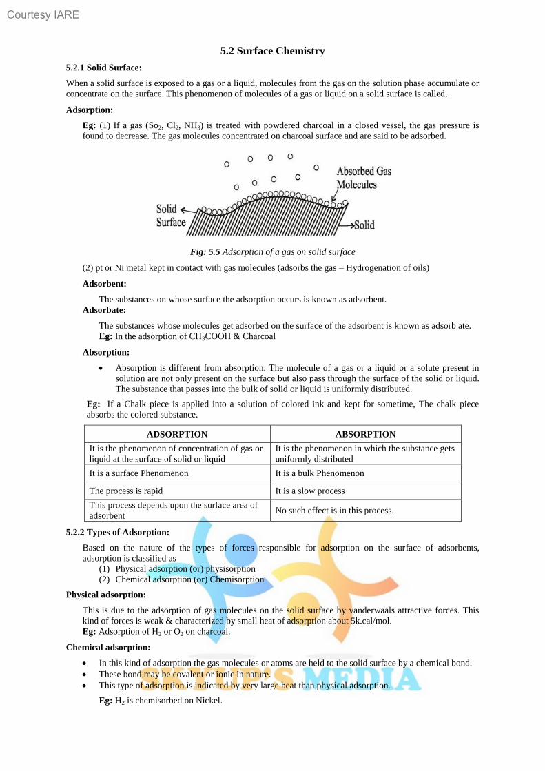
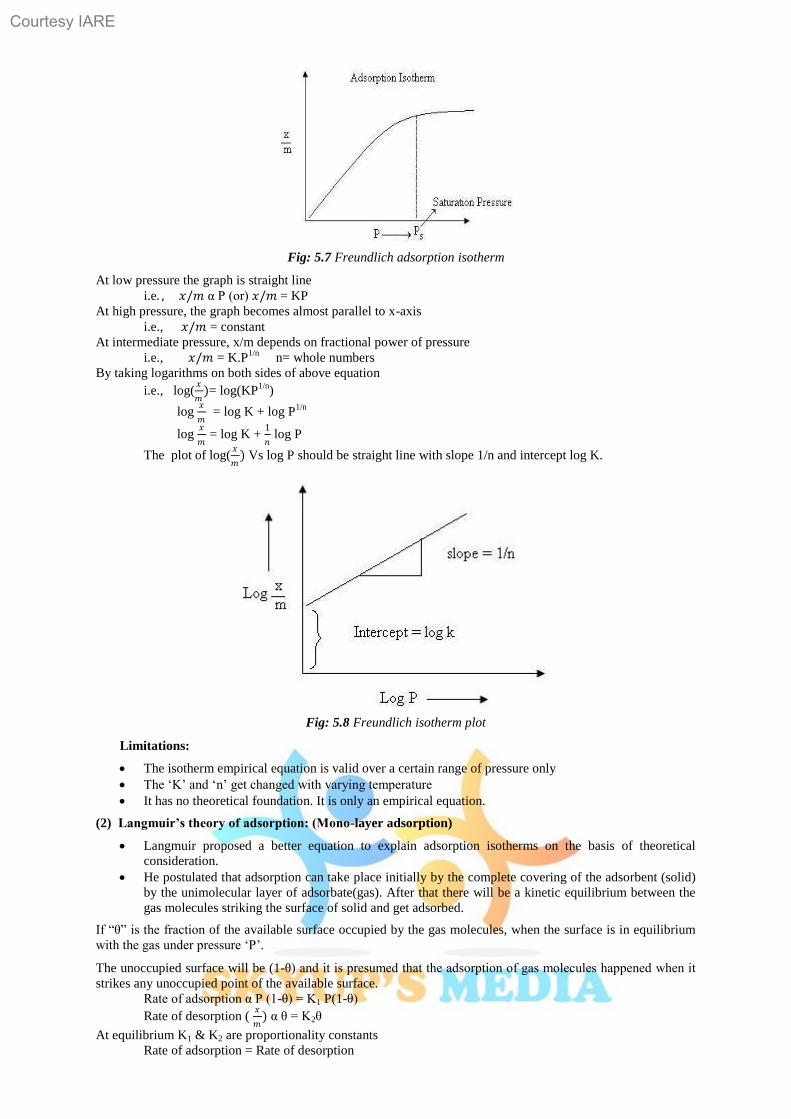
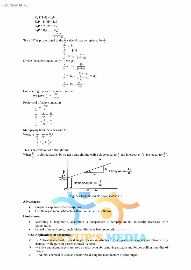
Courtesy IARE
1
INSTITUTE OF AERONAUTICAL ENGINEERING Dundigal, Hyderabad -500 043.
FRESHMAN ENGINEERING
Unit-I Electro Chemistry and Corrosion
Synopsis:
1.1 Electrochemistry & Batteries
1.1.1 Concept of electrochemistry- Definitions
1.1.2 Conduct metric titrations
1.1.3 Galvanic cell
1.1.4 Nernst equation and it‟s applications
1.1.5 Types of electrodes
1.1.6 Concentration cells
1.1.7 Potentiometric titrations
1.1.8 Batteries
1.1.9 Fuel cells
1.1.10 Numerical problems
1.2 Corrosion & it’s control
1.2.1Causes and effects
1.2.2 Theories
1.2.3 Types of corrosion
1.2.4 Factors affecting the rate of corrosion
1.2.5 Corrosion control methods
1.2.6 Surface coatings (Metallic coatings)
1.2.7 Organic coatings
Courtesy IARE
2
Introduction:
Chemistry is the Study of matter, its properties and the changes it may undergo. All matter is electrical in
nature. An atom is made up of sub atomic particles like electors, protons and neutrons etc.
Electro chemistry is a branch of chemistry which deals with the transformation of electrical energy into
chemical energy or chemical into electrical energy.
1.1.1Concept of electrochemistry:
Electrical Conduction: The substances are divided into 4 types depending upon their capability of flow of
electrons.
i) Conductors: The Substances which allows electricity to pass through them are called conductors.
Ex: - Metals, metal sulphides, acids, alkalis, salt sol. and fused salts.
The electrical conductors are of two types.
1. Metallic or Electronic conductors.
2. Electrolytic conductors
ii) Non-conductors: The substances which do not allow electricity are called non-conductors.
Ex: - Pure water, dry wood, rubber, paper, non-metals etc.
iii) Semi conductors: The substances which partially conduct electricity are called semi- conductors.
The conducting properties of semi-conducting properties are increased by the addition of certain
impurities called “doping”.
Ex: - „Si‟ and addition of V group elements like „P‟, „Si‟ produces n-type semi-conductor. On addition
of iii group element like „B‟, Al, and „Si‟ produces p-type of semi-conductor.
Differences between Metallic Conductors and Electrolytic Conductors
Metallic conductors Electrolytic conductors
1. Conductance is due to the flow of
electrons.
2. It does not result any chemical change.
3. Metallic conduction decreases with
increase in temperature.
4. It does not involve any transfer of
matter.
1. Conductance is due to the movement of
ions in a solution.
2. Chemical reactions take place at the
electrodes.
3. Electrolytic conduction increases with
increase in temperature.
4. It involves transfer of matter.
Electrical Resistance – Ohm’s law:
The current strength flowing through a conductor at uniform temperature is directly proportional to the
potential difference applied across to conductor.
V α I
Where,
I → current strength
V → potential difference.
V = IR
Where,
R-Proportionality const which is called resistance
R = V/I
Units for Resistance is Ohm
Specific resistance (or) Resistivity:
Ohm found that the solution of electrolyte also offers resistance to flow of current in the solution.
“The resistance (R) of a conductor is directly proportional to it‟s length and inversely proportional to
it‟s cross sectional area (a)”
R α 𝑙
R α a
R α 𝑙/𝑎
R = ρ → 𝑙/𝑎
Where,
ρ - Specific resistance.
If 𝑙 = 1 cm and a = 1cm2 then R = ρ then the specific resistance is defined as “The resistance offered
by a material of unit length and unit area of cross section is called specific resistance”.
ρ = R/ 𝑙 /a
Courtesy IARE
3
= R×a/ 𝑙
Units: ohm × cm2/cm = ohm cm
Conductance:
The reciprocal of resistance is called Conductance
L = 1/𝑅
Units: Ohm -1
(or) mho (C.G.S)
Siemens (S) (M.K.S)
Specific Conductance (or) Conductivity:
Reciprocal of specific resistance is known as specific conductance.
1/R = 1/ρ ×1/𝑙/𝑎
L= k.a/l
K = L/a/l = L× l/a
Units: Ohm-1
cm-1
If l = 1cm, a =1 cm2 then K = L, then the specific conductance is defined as.
“The conductance of a solution enclosed between two parallel electrodes of unit area of cross – section
separated by unit distance”.
Equivalent Conductance (or) Equivalent Conductivity:
It is defined as the conductance of all ions produced by the dissociation of I gm equivalent of an
electrolyte dissolved in certain volume „V‟ of the solvent at constant temperature.
^v = 𝐾 𝑋 1000
𝑁 =
𝑺.𝑷 𝑪𝒐𝒏𝒅𝒖𝒄𝒕𝒂𝒏𝒄𝒆 𝑿 𝟏𝟎𝟎𝟎
𝐍
Units: 𝑜𝑚−1 𝑐𝑚−1 𝑐𝑚3
𝑒𝑞 . = Ohm
-1 cm
2 eq
-1
Molar Conductance (or) Molar Conductivity:
It is defined as the conductance of all ions produced by the dissociation of 1gm mol. Wt. of electrolyte
dissolved in certain volume „V‟ of the solvent at const. Temperature.
µ = 𝒌𝑿𝟏𝟎𝟎𝟎
𝑴 =
𝑺.𝑷 𝑪𝒐𝒏𝒅𝒖𝒄𝒕𝒂𝒏𝒄𝒆 𝑿 𝟏𝟎𝟎𝟎
𝑴
Units: 𝑜𝑚−1
𝑚𝑜𝑙𝑒𝑠 /𝑙𝑖 =
𝑜𝑚−1𝑐𝑚−1 𝑐𝑚3
𝑚𝑜𝑙𝑒 = Ohm
-1 cm
2 mole
-1
Cell Constant:
It is a constant, characteristic of the cell in which the electrolyte is taken and it‟s value depends on the
distance between the electrodes and the area of cross – section of electrodes.
Cell Constant = 𝑫𝒊𝒔𝒕𝒂𝒏𝒄𝒆 𝒃𝒆𝒕𝒘𝒆𝒆𝒏 𝒕𝒉𝒆 𝒆𝒍𝒆𝒄𝒕𝒓𝒐𝒅𝒆𝒔
𝑨 𝒓𝒆𝒂 𝒐𝒇 𝒄𝒓𝒐𝒔𝒔−𝒔𝒆𝒄𝒕𝒊𝒐𝒏 𝒐𝒇 𝒆𝒂𝒄𝒉 𝒆𝒍𝒆𝒄𝒕𝒓𝒐𝒅𝒆 =
𝒍
𝒂
Specific conductance K = Lx 𝒍
𝒂
K = 𝟏
𝑹×
𝒍
𝒂
𝒍
𝒂 = K × R
Cell Constant = specific conductance × resistance
Variation of Conductance with dilution:
The conductance increases with increase in the concentration of the electrolyte to a certain maximum level
and decreases on further increase in the concentration. This is because, on increase in the concentration, the
population of free ions increases and these cons get closer and the electrostatic force of attractions and the
viscosity of the electrolyte increases. These factors tend to reduce the conductance of the solution. But
equivalent conductance is inversely proportional to the concentration of electrolyte and hence increases
with increase in dilution.
Courtesy IARE
4
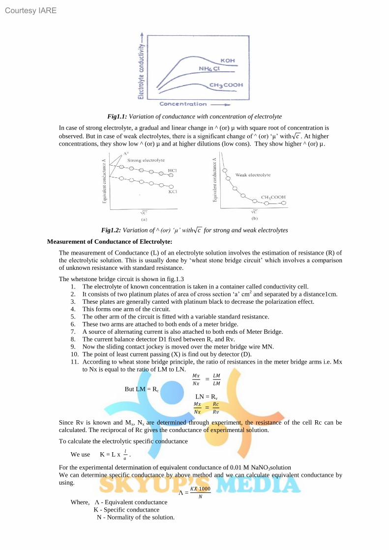
Fig1.1: Variation of conductance with concentration of electrolyte
In case of strong electrolyte, a gradual and linear change in ^ (or) µ with square root of concentration is
observed. But in case of weak electrolytes, there is a significant change of ^ (or) „µ‟ with 𝑐 . At higher
concentrations, they show low ^ (or) µ and at higher dilutions (low cons). They show higher ^ (or) µ.
Fig1.2: Variation of ^ (or) ‘µ’ with 𝑐 for strong and weak electrolytes
Measurement of Conductance of Electrolyte:
The measurement of Conductance (L) of an electrolyte solution involves the estimation of resistance (R) of
the electrolytic solution. This is usually done by „wheat stone bridge circuit‟ which involves a comparison
of unknown resistance with standard resistance.
The whetstone bridge circuit is shown in fig.1.3
1. The electrolyte of known concentration is taken in a container called conductivity cell.
2. It consists of two platinum plates of area of cross section „a‟ cm2 and separated by a distance1cm.
3. These plates are generally canted with platinum black to decrease the polarization effect.
4. This forms one arm of the circuit.
5. The other arm of the circuit is fitted with a variable standard resistance.
6. These two arms are attached to both ends of a meter bridge.
7. A source of alternating current is also attached to both ends of Meter Bridge.
8. The current balance detector D1 fixed between Rc and Rv.
9. Now the sliding contact jockey is moved over the meter bridge wire MN.
10. The point of least current passing (X) is find out by detector (D).
11. According to wheat stone bridge principle, the ratio of resistances in the meter bridge arms i.e. Mx
to Nx is equal to the ratio of LM to LN. 𝑀𝑥
𝑁𝑥 =
𝐿𝑀
𝐿𝑀
But LM = Rc
LN = Rv 𝑀𝑥
𝑁𝑥 =
𝑅𝑐
𝑅𝑣
Since Rv is known and Mx, Nx are determined through experiment, the resistance of the cell Rc can be
calculated. The reciprocal of Rc gives the conductance of experimental solution.
To calculate the electrolytic specific conductance
We use K = L x 𝑙
𝑎 .
For the experimental determination of equivalent conductance of 0.01 M NaNO3solution
We can determine specific conductance by above method and we can calculate equivalent conductance by
using.
Λ = 𝐾𝑋 1000
𝑁
Where, Λ - Equivalent conductance
K - Specific conductance
N - Normality of the solution.
Courtesy IARE
5
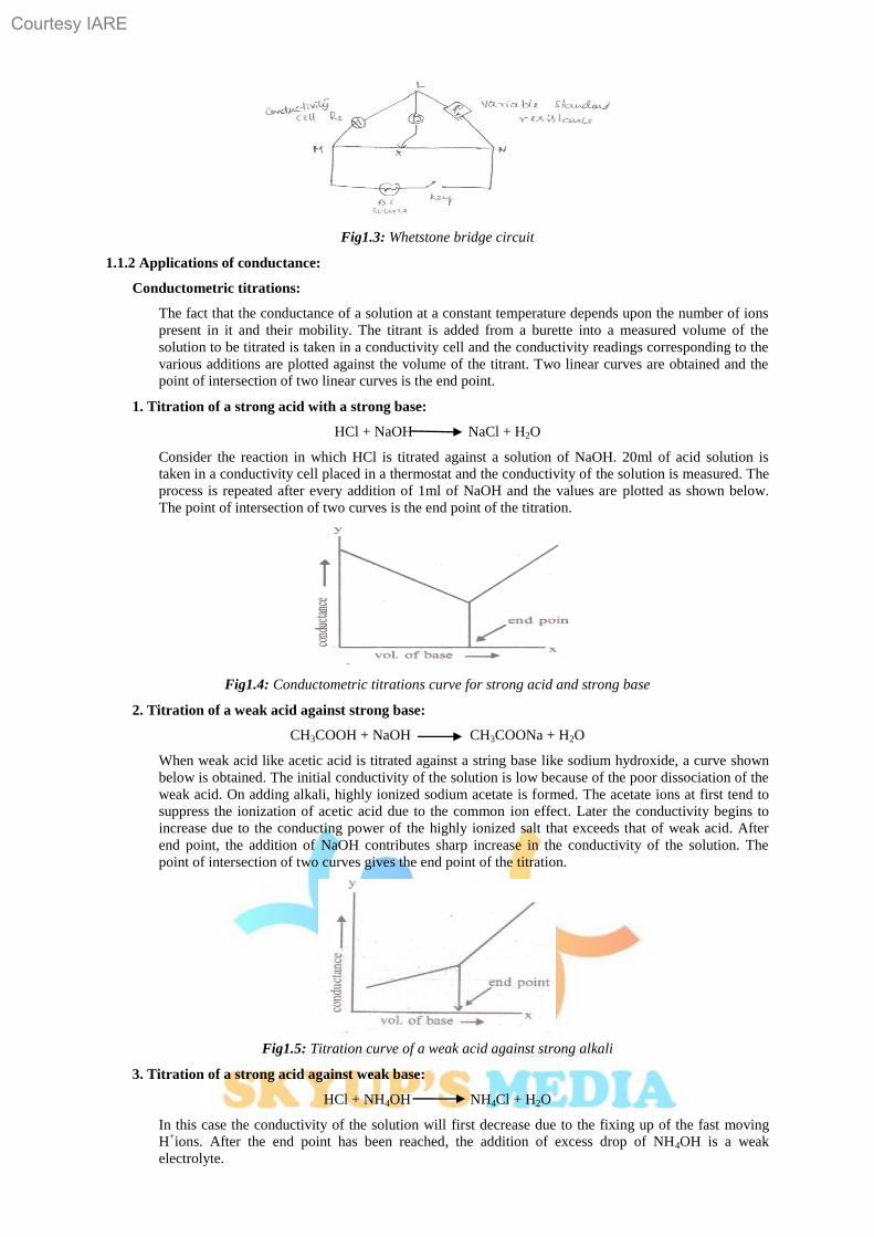
Fig1.3: Whetstone bridge circuit
1.1.2 Applications of conductance:
Conductometric titrations:
The fact that the conductance of a solution at a constant temperature depends upon the number of ions
present in it and their mobility. The titrant is added from a burette into a measured volume of the
solution to be titrated is taken in a conductivity cell and the conductivity readings corresponding to the
various additions are plotted against the volume of the titrant. Two linear curves are obtained and the
point of intersection of two linear curves is the end point.
1. Titration of a strong acid with a strong base:
HCl + NaOH NaCl + H2O
Consider the reaction in which HCl is titrated against a solution of NaOH. 20ml of acid solution is
taken in a conductivity cell placed in a thermostat and the conductivity of the solution is measured. The
process is repeated after every addition of 1ml of NaOH and the values are plotted as shown below.
The point of intersection of two curves is the end point of the titration.
Fig1.4: Conductometric titrations curve for strong acid and strong base
2. Titration of a weak acid against strong base:
CH3COOH + NaOH CH3COONa + H2O
When weak acid like acetic acid is titrated against a string base like sodium hydroxide, a curve shown
below is obtained. The initial conductivity of the solution is low because of the poor dissociation of the
weak acid. On adding alkali, highly ionized sodium acetate is formed. The acetate ions at first tend to
suppress the ionization of acetic acid due to the common ion effect. Later the conductivity begins to
increase due to the conducting power of the highly ionized salt that exceeds that of weak acid. After
end point, the addition of NaOH contributes sharp increase in the conductivity of the solution. The
point of intersection of two curves gives the end point of the titration.
Fig1.5: Titration curve of a weak acid against strong alkali
3. Titration of a strong acid against weak base:
HCl + NH4OH NH4Cl + H2O
In this case the conductivity of the solution will first decrease due to the fixing up of the fast moving
H+ions. After the end point has been reached, the addition of excess drop of NH4OH is a weak
electrolyte.
Courtesy IARE
6
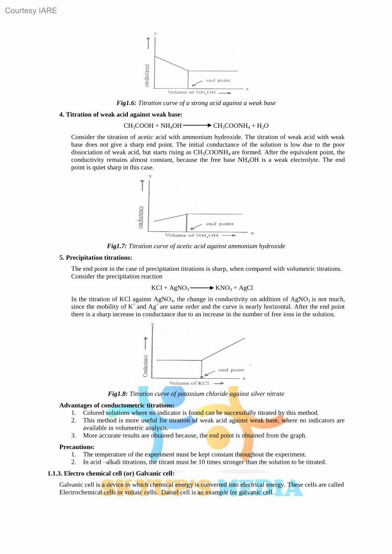
Fig1.6: Titration curve of a strong acid against a weak base
4. Titration of weak acid against weak base:
CH3COOH + NH4OH CH3COONH4 + H2O
Consider the titration of acetic acid with ammonium hydroxide. The titration of weak acid with weak
base does not give a sharp end point. The initial conductance of the solution is low due to the poor
dissociation of weak acid, but starts rising as CH3COONH4 are formed. After the equivalent point, the
conductivity remains almost constant, because the free base NH4OH is a weak electrolyte. The end
point is quiet sharp in this case.
Fig1.7: Titration curve of acetic acid against ammonium hydroxide
5. Precipitation titrations:
The end point in the case of precipitation titrations is sharp, when compared with volumetric titrations.
Consider the precipitation reaction
KCl + AgNO3 KNO3 + AgCl
In the titration of KCl against AgNO3, the change in conductivity on addition of AgNO3 is not much,
since the mobility of K+
and Ag+
are same order and the curve is nearly horizontal. After the end point
there is a sharp increase in conductance due to an increase in the number of free ions in the solution.
Fig1.8: Titration curve of potassium chloride against silver nitrate
Advantages of conductometric titrations:
1. Colored solutions where no indicator is found can be successfully titrated by this method.
2. This method is more useful for titration of weak acid against weak base, where no indicators are
available in volumetric analysis.
3. More accurate results are obtained because, the end point is obtained from the graph.
Precautions:
1. The temperature of the experiment must be kept constant throughout the experiment.
2. In acid –alkali titrations, the titrant must be 10 times stronger than the solution to be titrated.
1.1.3. Electro chemical cell (or) Galvanic cell:
Galvanic cell is a device in which chemical energy is converted into electrical energy. These cells are called
Electrochemical cells or voltaic cells. Daniel cell is an example for galvanic cell.
Courtesy IARE
7
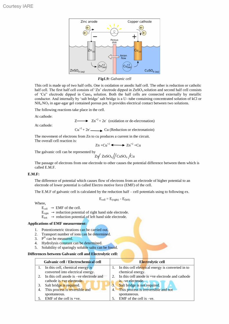
Fig1.9: Galvanic cell
This cell is made up of two half cells. One is oxidation or anodic half cell. The other is reduction or catholic
half cell. The first half cell consists of „Zn‟ electrode dipped in ZnSO4 solution and second half cell consists
of „Cu” electrode dipped in Cuso4 solution. Both the half cells are connected externally by metallic
conductor. And internally by „salt bridge‟ salt bridge is a U- tube containing concentrated solution of kCl or
NH4 NO3 in agar-agar gel contained porous pot. It provides electrical contact between two solutions.
The following reactions take place in the cell.
At cathode:
Z
Zn+2
+ 2e-
(oxidation or de-elecronation)
At cathode:
Cu+2
+ 2e- Cu (Reduction or electronatioin)
The movement of electrons from Zn to cu produces a current in the circuit.
The overall cell reaction is:
Zn +Cu+2
Zn+2
+Cu
The galvanic cell can be represented by
Zn ZnSO4 CuSO4 Cu
The passage of electrons from one electrode to other causes the potential difference between them which is
called E.M.F.
E.M.F:
The difference of potential which causes flow of electrons from an electrode of higher potential to an
electrode of lower potential is called Electro motive force (EMF) of the cell.
The E.M.F of galvanic cell is calculated by the reduction half – cell potentials using to following ex.
Ecell = E(right) - E(left)
Where,
Ecell → EMF of the cell.
Eright → reduction potential of right hand side electrode.
Eleft → reduction potential of left hand side electrode.
Applications of EMF measurement:
1. Potentiometric titrations can be carried out.
2. Transport number of ions can be determined.
3. PH can be measured.
4. Hydrolysis constant can be determined.
5. Solubility of sparingly soluble salts can be found.
Differences between Galvanic cell and Electrolytic cell:
Galvanic cell / Electrochemical cell Electrolytic cell
1. In this cell, chemical energy is
converted into electrical energy.
2. In this cell anode is –ve electrode and
cathode is +ve electrode.
3. Salt bridge is required.
4. This process is reversible and
spontaneous.
5. EMF of the cell is +ve.
1. In this cell electrical energy is converted in to
chemical energy.
2. In this cell anode is +ve electrode and cathode
is –ve electrode.
3. Salt bridge is not required.
4. This process is irreversible and not
spontaneous.
5. EMF of the cell is –ve.
Courtesy IARE
8
Single electrode potential (E):
When a metal rod dipped in it‟s salt solution, the metal atom tends either to lose electrons (oxidation) or to
accept electrons (reduction). The process of oxidation or reduction depends on the nature of metal. In this
process, there develops a potential between the metal atom and it‟s corresponding ion called the electrode
potential. There is a dynamic equilibrium between the metal and metal ion and the potential diff. between
the two is called electrode potential. It is measured in volts.
Standard electrode potential (E0):
The potential exhibited by single at unit concentration of it‟s metal ion at 250 c is called standard electrode
potential (E0)
Ex: E of cu+2
/ cu = E0 when concentration of cu
+2 is IM. E
0 value of single electrode is determined
experimentally by combining the single electrode with standard hydrogen electrode.
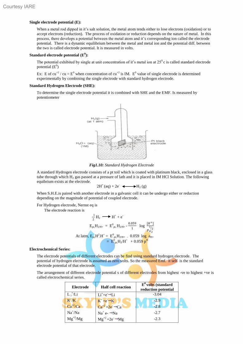
Standard Hydrogen Electrode (SHE):
To determine the single electrode potential it is combined with SHE and the EMF. Is measured by
potentiometer
Fig1.10: Standard Hydrogen Electrode
A standard Hydrogen electrode consists of a pt toil which is coated with platinum black, enclosed in a glass
tube through which H2 gas passed at a pressure of lath and it is placed in IM HCl Solution. The following
equibrium exists at the electrode.
2H+
(aq) + 2e-
H2 (g)
When S.H.E.is paired with another electrode in a galvanic cell it can be undergo either or reduction
depending on the magnitude of potential of coupled electrode.
For Hydrogen electrode, Nernst eq is
The electrode reaction is 1
2 H2
H+ + e
-
Ept,H2/H+ = E0pt, H2/H+ -
0.059
1 log
[𝐻+]
𝑝𝐻2
12
At latm, Ept,H2
/H+ = E
0pt,H2/H+ - 0.059 log aH+
= E0pt,H2/H
+ + 0.059 p
H
Electrochemical Series:
The electrode potentials of different electrodes can be find using standard hydrogen electrode. The
potential of hydrogen electrode is assumed as zero volts. So the measured Emf. it self is the standard
electrode potential of that electrode.
The arrangement of different electrode potential s of different electrodes from highest -ve to highest +ve is
called electrochemical series.
Electrode Half cell reaction E
0 volts (standard
reduction potential
L i+/Li
K+/K
Ca+2
/Ca
Na+/Na
Mg+2
/Mg
Li++e
-Li
K+
+e-
K
Ca+2
+2e-
Ca
Na+ e- Na
Mg+2
+2e-
Mg
-3.04
-2.9
-2.8
-2.7
-2.3
Courtesy IARE
9
Zn+2
/Zn
Fe+2
/Fe
H+/H2,pf
Cu+2
/Cu
Ag+/Ag
Pt,Cl 2/Cl -
Pt,F2/F-
Zn+2
+2e- Zn
Fe+2
+2e- Fe
H+
+ e-→
1
2
H2
Cu+2
+ 2e-
Cu
Ag+
+ e-
Ag
Cl2+ 2e- 2Cl
-
F2 + 2e-
2F--
-0.76
-0.4
+ 0
+0.15
+ 0.7
+ 1.3
+ 2.8
From the above series we can understand that the metals with higher –ve potentials are stronger reducing
agents, and the metals with higher +ve potentials are stronger oxidizing agents. The metals with higher –ve
potentials displaces a metals with lower –ve potentials.
1.1.4 Nernst Equation:
Nernst studied the theoretical relationship between electrode reaction and the corresponding cell e.m.f. This
relationship generally Known as Nernst equation.
Consider a galvanic cell
aA + bB
cC + dD.
Where,
a,b,c,d represents no. of moles respectively at equilibrium.
The Nernst eq‟ for the cell is written as
Ecell = E0cell -
𝑹𝑻
𝒏𝒇 ln
[𝐶]𝑐 [𝐷]𝑑
[𝐴]𝑎 [𝐵]𝑏
= E0cell -
𝟐.𝟑𝟎𝟑𝑹𝑻
𝒏𝒇 log
[𝐶]𝑐 [𝐷]𝑑
[𝐴]𝑎 [𝐵]𝑏
R = 8.314 J/K. J = 298K. F = 96, 500 columbs.
By substituting the values in the eq‟
Ecell = E0cell -
𝟎.𝟎𝟓𝟗
𝒏 log
[𝐶]𝑐 [𝐷]𝑑
[𝐴]𝑎 [𝐵]𝑏
1.1.5 Reference Electrodes:
Because of the inconveniences in the usage of Hydrogen electrode like maintenance of accurate pressure,
inconvenience in handling gas secondary electrodes were developed.
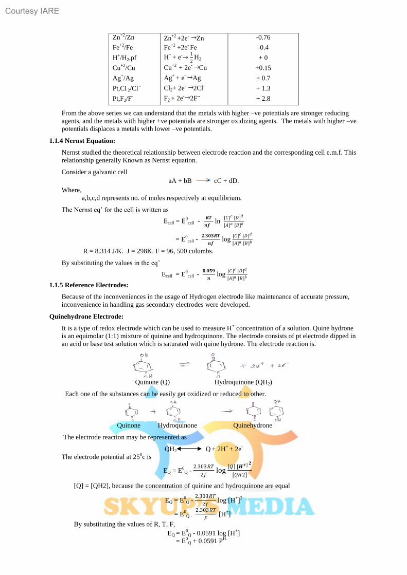
Quinehydrone Electrode:
It is a type of redox electrode which can be used to measure H+ concentration of a solution. Quine hydrone
is an equimolar (1:1) mixture of quinine and hydroquinone. The electrode consists of pt electrode dipped in
an acid or base test solution which is saturated with quine hydrone. The electrode reaction is.
Quinone (Q) Hydroquinone (QH2)
Each one of the substances can be easily get oxidized or reduced to other.
Quinone Hydroquinone Quinehydrone
The electrode reaction may be represented as
QH2 Q + 2H
+ + 2e
-
The electrode potential at 250c is
EQ = E0
Q - 2.303𝑅𝑇
2𝑓 log
𝑄 [𝑯+] 𝟐
[𝑄𝐻2]
[Q] = [QH2], because the concentration of quinine and hydroquinone are equal
EQ = E0Q -
2.303𝑅𝑇
2𝑓 log [H
+]
2
= E0Q -
2.303𝑅𝑇
𝐹 [H+]
By substituting the values of R, T, F,
EQ = E0
Q - 0.0591 log [H+]
= E0Q + 0.0591 P
H.
Courtesy IARE
10
This eq‟ is used to calculate the pH is EQ and E
0Q values are known.
Advantages:
1. This electrode is simple to set up and needs no removal of air.
2. We can measure pH
value quicker than hydrogen gas electrode
Limitations:
1. This electrode cannot be used at PH values greater than 8.
2. This electrode fails in presence of strong oxidizing and reducing agents.
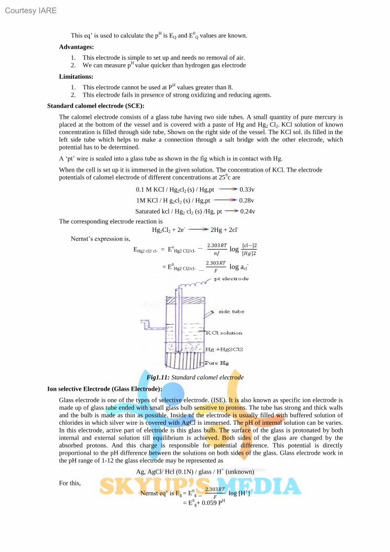
Standard calomel electrode (SCE):
The calomel electrode consists of a glass tube having two side tubes. A small quantity of pure mercury is
placed at the bottom of the vessel and is covered with a paste of Hg and Hg2 Cl2. KCl solution of known
concentration is filled through side tube, Shown on the right side of the vessel. The KCl sol. iIs filled in the
left side tube which helps to make a connection through a salt bridge with the other electrode, which
potential has to be determined.
A „pt‟ wire is sealed into a glass tube as shown in the fig which is in contact with Hg.
When the cell is set up it is immersed in the given solution. The concentration of KCl. The electrode
potentials of calomel electrode of different concentrations at 250c are
0.1 M KCl / Hg2cl2 (s) / Hg,pt 0.33v
1M KCl / H g2cl2 (s) / Hg,pt 0.28v
Saturated kcl / Hg2 cl2 (s) /Hg, pt 0.24v
The corresponding electrode reaction is
Hg2Cl2 + 2e- 2Hg + 2cl
-
Nernst‟s expression is,
EHg2 cl2/ cl- = EoHg2 Cl2/cl-
__ 2.303𝑅𝑇
𝑛𝑓
log
[cl−]2
[𝐻𝑔]2
= E0Hg2 Cl2/cl- __
2.303𝑅𝑇
𝐹 log acl-
Fig1.11: Standard calomel electrode
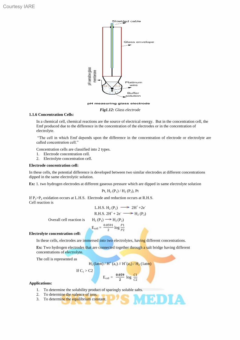
Ion selective Electrode (Glass Electrode):
Glass electrode is one of the types of selective electrode. (ISE). It is also known as specific ion electrode is
made up of glass tube ended with small glass bulb sensitive to protons. The tube has strong and thick walls
and the bulb is made as thin as possible. Inside of the electrode is usually filled with buffered solution of
chlorides in which silver wire is covered with AgCl is immersed. The pH of internal solution can be varies.
In this electrode, active part of electrode is this glass bulb. The surface of the glass is protonated by both
internal and external solution till equilibrium is achieved. Both sides of the glass are changed by the
absorbed protons. And this charge is responsible for potential difference. This potential is directly
proportional to the pH difference between the solutions on both sides of the glass. Glass electrode work in
the pH range of 1-12 the glass electrode may be represented as
Ag, AgCl/ Hcl (0.1N) / glass / H+ (unknown)
For this,
Nernst eq‟ is Eg = E0
g _ 2.303𝑅𝑇
𝐹 log [H
+]
= E0
g+ 0.059 PH
Courtesy IARE
11
Fig1.12: Glass electrode
1.1.6 Concentration Cells:
In a chemical cell, chemical reactions are the source of electrical energy. But in the concentration cell, the
Emf produced due to the difference in the concentration of the electrodes or in the concentration of
electrolyte.
“The cell in which Emf depends upon the difference in the concentration of electrode or electrolyte are
called concentration cell.”
Concentration cells are classified into 2 types.
1. Electrode concentration cell.
2. Electrolyte concentration cell.
Electrode concentration cell:
In these cells, the potential difference is developed between two similar electrodes at different concentrations
dipped in the same electrolytic solution.
Ex: 1. two hydrogen electrodes at different gaseous pressure which are dipped in same electrolyte solution
Pt, H2 (P1) / H2 (P2), Pt
If P1>P2 oxidation occurs at L.H.S. Electrode and reduction occurs at R.H.S.
Cell reaction is
L.H.S. H2 (P1) 2H+
+2e-
R.H.S. 2H+
+ 2e-
H2 (P2)
Overall cell reaction is H2 (P1) H2 (P2)
Ecell = 0.0591
2 log
𝑃1
𝑃2
Electrolyte concentration cell:
In these cells, electrodes are immersed into two electrolytes, having different concentrations.
Ex: Two hydrogen electrodes that are connected together through a salt bridge having different
concentrations of electrolyte.
The cell is represented as
H2 (latm) / H+ (a1) // H
+(a2) / H2 (1atm)
If C1 > C2
Ecell = 𝟎.𝟎𝟓𝟗
𝟐 log
𝐶1
𝐶2
Applications:
1. To determine the solubility product of sparingly soluble salts.
2. To determine the valence of ions.
3. To determine the equilibrium constant.
Courtesy IARE
12
Differences between concentration cells and Electrolytic cells:
Concentration cells Electrolytic cells
1. In this cell, chemical energy is converted into
electrical energy.
2. In this cell, anode is –ve , cathode is +ve.
3. Salt bridge is required.
4. Reversible and spontaneous.
5. E.m.f. of the cell is +ve
1. In this cell, electrical energy is converted into
chemical energy.
2. In this cell anode is +ve cathode is -ve .
3. Salt bridge not required.
4. Irreversible and not spontaneous.
5. E.m.f of the cell is –ve
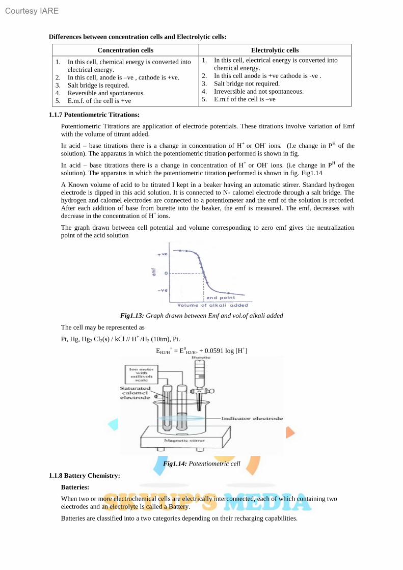
1.1.7 Potentiometric Titrations:
Potentiometric Titrations are application of electrode potentials. These titrations involve variation of Emf
with the volume of titrant added.
In acid – base titrations there is a change in concentration of H+
or OH- ions. (I.e change in P
H of the
solution). The apparatus in which the potentiometric titration performed is shown in fig.
In acid – base titrations there is a change in concentration of H+
or OH- ions. (i.e change in P
H of the
solution). The apparatus in which the potentiometric titration performed is shown in fig. Fig1.14
A Known volume of acid to be titrated I kept in a beaker having an automatic stirrer. Standard hydrogen
electrode is dipped in this acid solution. It is connected to N- calomel electrode through a salt bridge. The
hydrogen and calomel electrodes are connected to a potentiometer and the emf of the solution is recorded.
After each addition of base from burette into the beaker, the emf is measured. The emf, decreases with
decrease in the concentration of H+
ions.
The graph drawn between cell potential and volume corresponding to zero emf gives the neutralization
point of the acid solution
Fig1.13: Graph drawn between Emf and vol.of alkali added
The cell may be represented as
Pt, Hg, Hg2 Cl2(s) / kCl // H+
/H2 (10tm), Pt.
EH2/H+ = E
0H2/H+ + 0.0591 log [H
+]
Fig1.14: Potentiometric cell
1.1.8 Battery Chemistry:
Batteries:
When two or more electrochemical cells are electrically interconnected, each of which containing two
electrodes and an electrolyte is called a Battery.
Batteries are classified into a two categories depending on their recharging capabilities.
Courtesy IARE
13
Primary Batteries:
“These are non-rechargeable and are meant for single use and to be discarded after use”.
These are non-reversed and are less expensive and are offer used in ordinary gadgets like torch lights,
watches and toys.
Ex: Leclanche cell, Dry cell.
Secondary Batteries:
These are rechargble and are meant for multi cycle use. After every use the electrochemical reaction could
be reversed by external application fades or lost due to leakage or internal short circuit. Eg: Lead-acid cell,
Ni/cd cell
Differences between Primary and secondary batteries:
Primary cells Secondary cells
1. These are non-rechargeable and meant for a
single use and to be discarded after use.
2. Cell reaction is not reversible.
3. Cannot be rechargeable.
4. Less expensive.
5. Can be used as long as the materials are
active in their composition.
Ex: Leclanche cell, „Li‟ Cells.
1. These are rechargeable and meant for multi
cycle use.
2. Cell reaction can be reversed.
3. Can be rechargeable.
4. Expensive.
5. Can be used again and again by recharging
the cell.
Ex: Lead- acid cell, Ni-cd cells.
Primary Batteries:
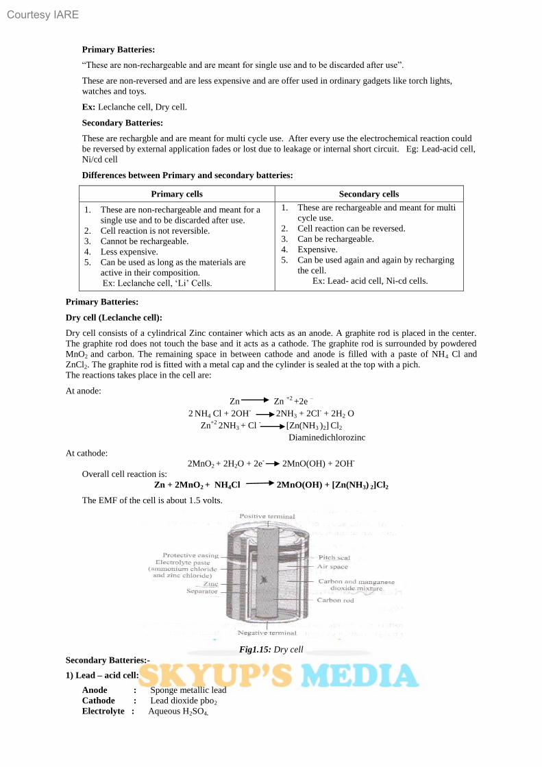
Dry cell (Leclanche cell):
Dry cell consists of a cylindrical Zinc container which acts as an anode. A graphite rod is placed in the center.
The graphite rod does not touch the base and it acts as a cathode. The graphite rod is surrounded by powdered
MnO2 and carbon. The remaining space in between cathode and anode is filled with a paste of NH4 Cl and
ZnCl2. The graphite rod is fitted with a metal cap and the cylinder is sealed at the top with a pich.
The reactions takes place in the cell are:
At anode:
Zn Zn +2
+2e –
2 NH4 Cl + 2OH
- 2NH3 + 2Cl
- + 2H2 O
Zn+2
2NH3 + Cl -
[Zn(NH3 )2] Cl2
Diaminedichlorozinc
At cathode:
2MnO2 + 2H2O + 2e-
2MnO(OH) + 2OH-
Overall cell reaction is:
Zn + 2MnO2 + NH4Cl 2MnO(OH) + [Zn(NH3) 2]Cl2
The EMF of the cell is about 1.5 volts.
Fig1.15: Dry cell
Secondary Batteries:-
1) Lead – acid cell:
Anode : Sponge metallic lead
Cathode : Lead dioxide pbo2
Electrolyte : Aqueous H2SO4.
Courtesy IARE
14
Cell reactions:
Pb + SO4-2
PbSO4 + 2e- + 0.356v
PbO2 +SO4-2
+ 2e-
PbSO4 + 2H2o + 1.685v.
The e.m.f. produced by the cell is 2v
Applications: 1. Automobile and construction equipment.
2. Standby / backup system.
3. For engine batteries
Advantages:
Low cost, long life cycle, Ability to withstand mistreatment, perform well in high and low temperature.
2) Nickel – Cadmium cells: (Ni-Cd Cell):
Anode : Cd
Cathode : Nickel oxy hydroxide NiOOH
Electrolyte : Aqueous KOH
Cell reactions:
Anode : Cd + 2OH- Cd (OH)2 + 2 e
-
Cathode : NiOOH + 2H2O + 2 e- Ni(OH)2H2O + OH
-
Applications:
Calculators, digital cameras, pagers, laptops, tape recorders, flash lights, medical devices, electrical
vehicles, space applications.
Advantages: Good performance in low temperature long life.
3) Lithium ion cells:
Anode: Carbon compound, graphite
Cathode: Lithium oxide
Applications: Laptops, cell phones, electric vehicles
Cathode consists of a layered crystal (graphite) into which the lithium is intercalated. Experimental cells
have also used lithiated metal oxide such as LiCoO2, LiNiO2, LiV2O5 etc.
Electrolytes are usually LiPF6, although this has a problem with aluminum corrosion, and so alternatives are
being sought. One such is LiBF4. The electrolyte in current production batteries is a patented liquid and
uses an organic solvent.
Membranes are necessary to separate the electrons from the ions. Currently the batteries in wide use have
micro porous polyethylene membranes.
Intercalation keeps the small ions (such as Li, Na and the other alkali metals) into the interstitial spaces in a
graphite crystal. This makes the graphite is conductive, dilutes the lithium for safety, is reasonably cheap,
and does not allow dendrites or other unwanted crystal structures of Li to form.
1.1.9 Fuel cells:
“Fuel cells are the cells by which the electrical energy is produced by the conversion of chemical energy of
a fuel.”
In these cells one or both of the reactants are not permanently contained in the cell but are continuously
supplied from the source external to the cell and the reaction products continuously removed from the cell.
Hydrogen – Oxygen Fuel cell:
There are many kinds of H2/O2 fuel cells are categorized on the basis of electrolyte used.
1. Proton Exchange membrane fuel cells ( PEMFC)
2. Alkaline Fuel cells (AFC)
3. Molten carbonate fuel cell.
4. Phosphoric acid fuel cells.
5. Solid oxide fuels.
Proton Exchange Membrane fuel cells (PEMFC):
In this cell, a proton-Conducting polymer membrane separates the anode and cathode. This is called “Solid
polymer electrolytic fuel cell”
Courtesy IARE
15
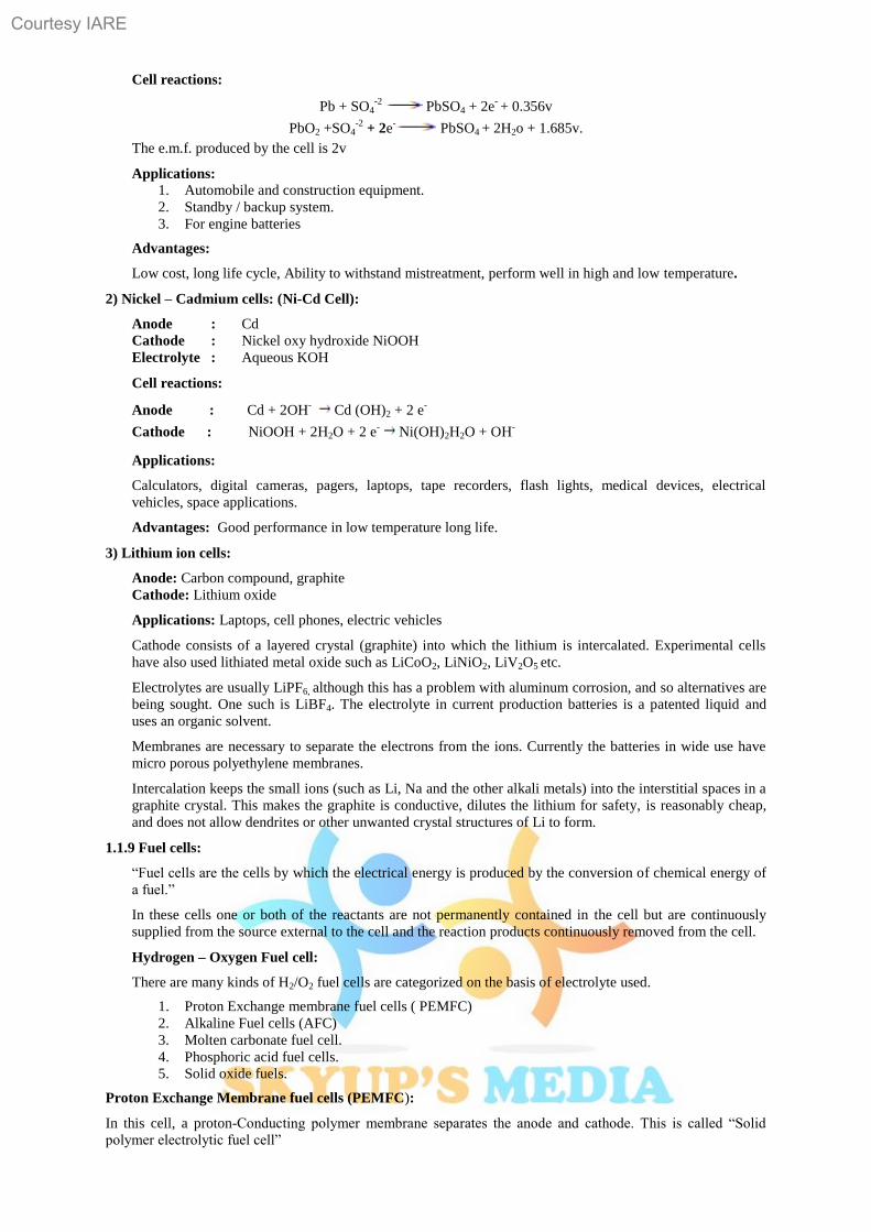
Like Galvanic cell, fuel cell also have two half cells. Both the half cells have porous graphite electrode. The
electrodes are placed in aqueous KOH or NaOH solution which acts as an electrolyte.
H2 and O2 are supplied at anode and cathode respectively at about 50 atm. pressure.
Fig1.16: H2 - O2 Fuel cell
At Anode :
2H2 + 4OH-
4H2o + 4e-
At Cathode :
O2 + 2H2O + 4e-
4OH-
Cell reactions is
2H2 + O2 2H2o
Advantage of fuel cells:
1. No emission of toxic gases and chemical wastes.
2. High efficiency (75-85%) of energy is converted into electrical energy.
3. The by-products are environmentally acceptable.
4. Unlike solar cells, fuel cells are compact and transportable.
5. Unlike acid cells, fuel cells are less corrosive.
6. No noise pollution like in generators and low thermal pollution.
1.1.10 Numerical Problems:
1Q. The resistance of 0.1 N solution of an electrolyte is 40 ohms. If the distance between the electrodes is 1.2cm
and the area of cross-section is 2.4cm. Calculate the equivalent conductivity.
A: Distance between electrodes l = 1.2cm
Area of cross-section a = 2.4cm2
Cell const. = = 0.5cm-1
Normality of given solution = 0.1 N.
Resistance R = 40 ohms.
Specific conductance K =
= = 0.0125
Equivalent Conductivity =
=
= 125 ohm-1
cm2 eq
-1
2Q: Calculate the cell Constant of a cell having a solution of concentration N/30 gm eq/li of an electrolyte
which showed the equivalent conductance of 120 Mhos cm2 eq
- 1, resistance 40 ohms.
A: Resistance R = 40 ohms.
Equivalent conductance of solution (A) = 120 mho cm2eq
-1
Concentration of solution N = gm eq/li
= 0.033N.
Cell constant = ?
Equivalent conductance =
Courtesy IARE
16
Specific conductance (K) =
=
= 0.00396
Cell constant = s p. conductance x Resistance
= 0.00396 x 40
= 0.1584 cm-1
3Q: Calculate the emf for the cell,
Zn/Zn+ // Ag
+ /Ag given E
0Zn+/Zn
+2 / Zn = 0.762v and E
0Ag+/Ag = 0.8 v
A: Given cell is zn/Zn+2
//Ag+/Ag.
E0
Zn+2/Zn = 0.762 v
E0
Ag+/Ag = 0.8 v
E0
cell = E0
right – E0left
= 0.8 – (-0.762)
= 1.562 v.
4Q: Calculate the E0cu
+2/cu, given E
- cu
+2/cu = 0.296 v and [cu
+2] = 0.015M.
A: Cell reai is cu cu+2
+ Ze-
E = E0 + log [cu
+2]
0.296 = E0 + log [cu
+2]
E0 = 0.296- log (0.015)
= 0.296 - 0.2955 (- 1.8239)
= 0.296 + 0.0538
= 0.3498v
5Q: Write the half cell and net cell reactions for the following cell,
Zn / Znso4 (aq) // cuso4 (aq) / cu.
Calculate the standard emf of the cell given,
E0
Zn+2
/Zn = 0.76 v and E0cu+2/cu = + 0.34 v.
A: Half cell reactions
At anode : Zn Zn+2
+ Ze-
At cathode : cu+2
+ e-
cu.
Net cell reaction = Zn + cu+2
Zn+2
+ cu.
E0
cell = E0
Cathode – E0
Anode.
= E0cu
+2/cu – E
0Zn
+2/ Zn
= 0.34 – (-0.76)
= 1.1 v.
Courtesy IARE
17
1.2 Corrosion and Its Control
Corrosion:
The surface of almost all the metals begin to decay more or less rapidly when exposed to atmospheric
gases, water or other reactive liquid medium.
The process of decay metal by environmental attack is known as corrosion.
Metals undergo corrosion and convert to their oxides, hydroxides, carbonates, sulphides etc.
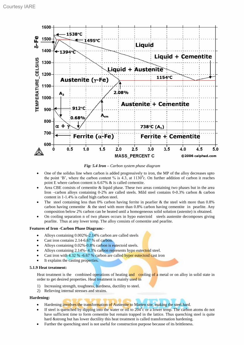
Ex. Iron undergoes corrosion to form reddish brown colour rust [Fe2O3. 3H2O].
Copper undergoes corrosion to form a green film of basic carbonate [CuCO3 + Cu(OH)2]
1.2.1 Causes of corrosion:
1. The metals exist in nature in the form of their minerals or ores, in the stable combined forms as oxides,
chlorides, silicates, carbonates, sulphides etc.
2. During the extraction of metals, these ores are reduced to metallic state by supplying considerable
amounts of energy.
3. Hence the isolated pure metals are regarded as excited states than their corresponding ores.
So metals have natural tendency to go back to their combined state (minerals/ores).
When metal is exposed to atmospheric gases, moisture, liquids etc., the metal surface reacts and forms more
thermodynamically stabled compounds.
Effects of corrosion
1. Wastage of metal in the form of its compounds.
2. The valuable metallic properties like conductivity, malleability, ductility etc. are lost due to corrosion.
3. Life span and efficiency of metallic parts of machinery and fabrications is reduced.
1.2.2 Theories of corrosion:
Dry corrosion or Chemical corrosion:
This type of Corrosion occurs mainly through the direct chemical action of atmospheric gasses like O2,
halogens, H2S, SO2, N2 or anhydrous inorganic liquid with the metal surface.
There are three types of chemical Corrosion:
(1) Oxidation corrosion
(2) Corrosion due to other gases
(3) Liquid metal corrosion
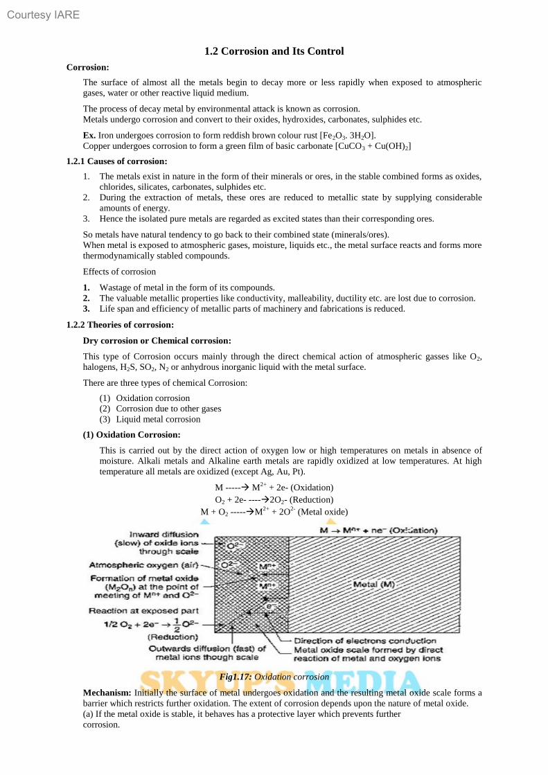
(1) Oxidation Corrosion:
This is carried out by the direct action of oxygen low or high temperatures on metals in absence of
moisture. Alkali metals and Alkaline earth metals are rapidly oxidized at low temperatures. At high
temperature all metals are oxidized (except Ag, Au, Pt).
M ----- M2+
+ 2e- (Oxidation)
O2 + 2e- ----2O2- (Reduction)
M + O2 -----M2+
+ 2O2-
(Metal oxide)
Fig1.17: Oxidation corrosion
Mechanism: Initially the surface of metal undergoes oxidation and the resulting metal oxide scale forms a
barrier which restricts further oxidation. The extent of corrosion depends upon the nature of metal oxide.
(a) If the metal oxide is stable, it behaves has a protective layer which prevents further
corrosion.
Courtesy IARE
18
E.g., The oxide films of Al, Sn, Pb, Cu, Cr, W etc. are stable and therefore further corrosion is prohibited.
(b) If the metal oxide unstable, the oxide layer formed decomposes back into metal and oxygen. Oxidation
corrosion is not possible.
Ex., Ag, Au and Pt do not undergo oxidation corrosion.
(c) If the metal oxide layer is volatile, then the oxide layer volatilizes after formation and leaves the
underlying metal surface exposed for further attack. This causes continuous corrosion which is excessive in
molybdenum oxide (MoO3).
(d) If the metal oxide layer is porous, the oxide layer formed has pores or cracks. In this case the
atmospheric oxygen penetrates through the pores or cracks and corrode the underlying metal surface. This
cause continuous corrosion till conversion of metal into its oxide is completed.
Ex: Alkali and alkaline earth metals (Li, Na, K, Mg etc.)
(2) Corrosion due to other gases:
This type of corrosion is due to gases like SO2, CO2, Cl2, H2S, F2 etc. In this corrosion, the extent of
corrosive effect depends mainly on the chemical affinity between the metal and the gas involved. The
degree of attack depends on the formation of protective or non protective films on the metal surface which
is explained on the basis of Pilling Bedworth rule.
(i) If the volume of the corrosion film formed is more than the underlying metal, it is strongly adherent,
non-porous does not allow the penetration of corrosive gases.
Ag + Cl2 ----2AgCl (protective film)
(ii) If the volume of the corrosion film formed is less than the underlying metal, it forms pores/cracks and
allow the penetration of corrosive gases leading to corrosion of the underlying metal.
Ex. In petroleum industry, H2S gas at high temperature reacts with steel forming a FeS scale. Fe (steel) +
H2S FeS (porous).
(3) Liquid metal corrosion:
This corrosion is due to chemical action of flowing liquid metal at high temperatures on solid metal or
alloy. The corrosion reaction involves either dissolution of a solid metal by a liquid metal or internal
penetration of the liquid metal into the solid metal.
Ex. Coolant (sodium metal) leads to corrosion of cadmium in nuclear reactors.
Wet corrosion or electrochemical corrosion:
This type of Corrosion occurs where a conducting liquid is in contact with the metal. This corrosion
occurs due to the existence of separate anodic and cathodic parts, between which current flows through
the conducting solution.
At anodic area, oxidation reaction occurs there by destroying the anodic metal either by dissolution or
formation of compounds. Hence corrosion always occurs at anodic parts.
Mechanism: Electrochemical corrosion involves flow of electrons between anode and cathode.
The anodic reaction involves dissolution of metal liberating free electrons.
M----- Mn+
+ ne-
The cathodic reaction consumes electrons with either evolution of hydrogen or absorption of oxygen which
depends on the nature of corrosive environment.
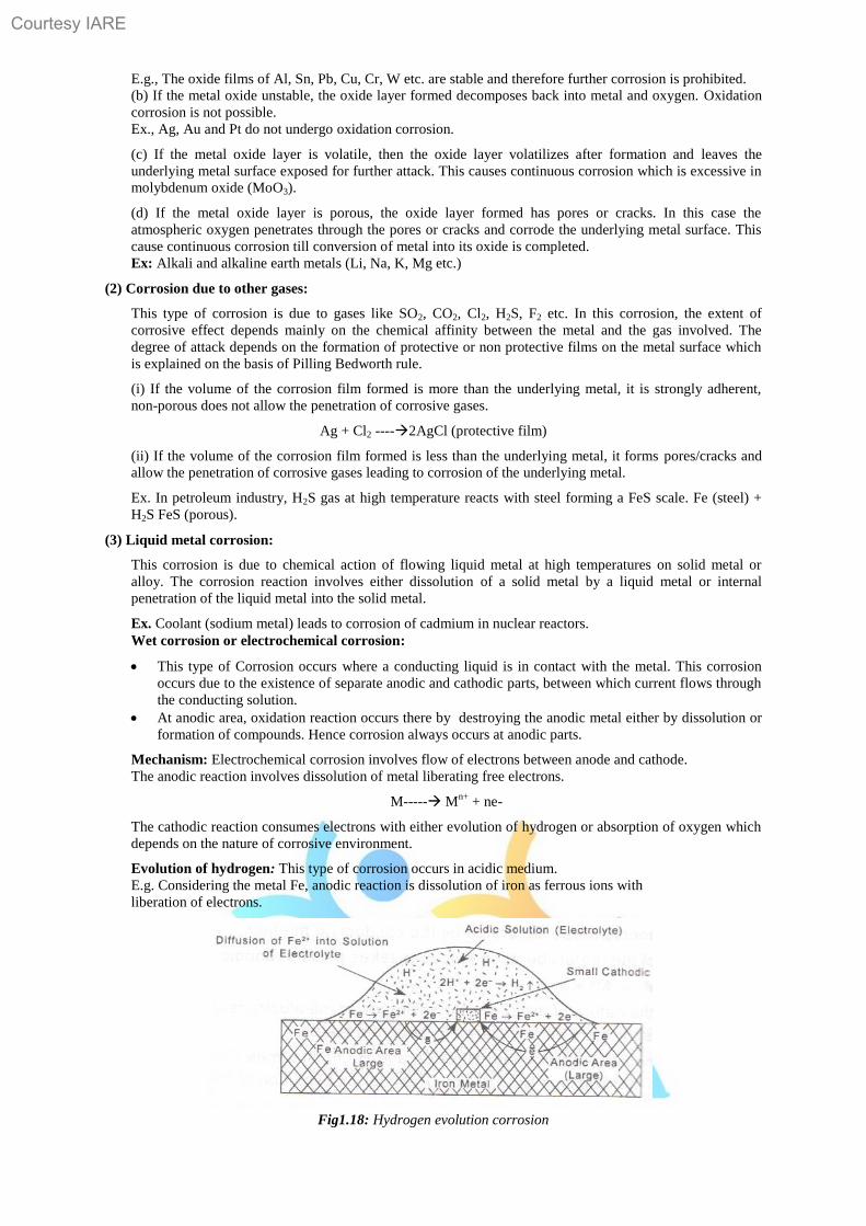
Evolution of hydrogen: This type of corrosion occurs in acidic medium.
E.g. Considering the metal Fe, anodic reaction is dissolution of iron as ferrous ions with
liberation of electrons.
Fig1.18: Hydrogen evolution corrosion
Courtesy IARE
19
Anode: Fe Fe2+
+ 2e- (Oxidation)
The electrons released flow through the metal from anode to cathode, whereas H+ ions of acidic solution are
eliminated as hydrogen gas.
Cathode: 2H+ + 2e
- ----H2 (Reduction)
The overall reaction is: Fe + 2H+ -----Fe
2+ + H2
This type of corrosion causes displacement of hydrogen ions from the solution by metal ions. All metals above
hydrogen in electrochemical series have a tendency to get dissolved in acidic solution with simultaneous
evolution of H2 gas. The anodes are large areas, whereas cathodes are small areas.
Absorption of Oxygen: For example, rusting of iron in neutral aqueous solution of electrolytes in presence of
atmospheric oxygen. Usually the surface of iron is coated with a thin film of iron oxide. If the film develops
cracks, anodic areas are created on the surface. While the metal parts act as cathodes. It shows that anodes are
small areas, while the rest metallic part forms large cathodes. The released electrons flow from anode to cathode
through iron metal.
At anode: Fe ----Fe2+
+ 2e- (Oxidation)
At cathode: ½ O2 + H2O + 2e- ---2OH
- (Reduction)
Overall reaction: Fe2+
+ 2OH------ Fe (OH)2
If oxygen is in excess, ferrous hydroxide is easily oxidized to ferric hydroxide.
4Fe (OH)2 + O2 + 2H2O → 4Fe(OH)3
The product called yellow rust corresponds to Fe2O3. 3H2O.
Fig.1.19: Oxygen absorption corrosion
1.2.3 Types of corrosion:
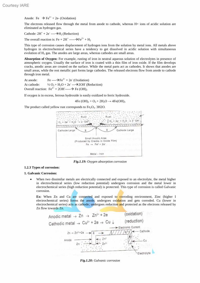
1. Galvanic Corrosion:
When two dissimilar metals are electrically connected and exposed to an electrolyte, the metal higher
in electrochemical series (low reduction potential) undergoes corrosion and the metal lower in
electrochemical series (high reduction potential) is protected. This type of corrosion is called Galvanic
corrosion.
Ex: When Zn and Cu are connected and exposed to corroding environment, Zinc (higher I
electrochemical series) forms the anode; undergoes oxidation and gets corroded. Cu (lower in
electrochemical series) acts as cathode; undergoes reduction and protected as the electrons released by
Zn flow towards Zn.
Fig.1.20: Galvanic corrosion
Courtesy IARE
20
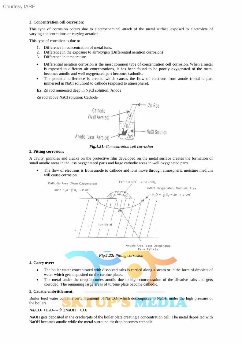
2. Concentration cell corrosion:
This type of corrosion occurs due to electrochemical attack of the metal surface exposed to electrolyte of
varying concentrations or varying aeration.
This type of corrosion is due to
1. Difference in concentration of metal ions.
2. Difference in the exposure to air/oxygen (Differential aeration corrosion)
3. Difference in temperature.
Differential aeration corrosion is the most common type of concentration cell corrosion. When a metal
is exposed to different air concentrations, it has been found to be poorly oxygenated of the metal
becomes anodic and well oxygenated part becomes cathodic.
The potential difference is created which causes the flow of electrons from anode (metallic part
immersed in NaCl solution) to cathode (exposed to atmosphere).
Ex: Zn rod immersed deep in NaCl solution: Anode
Zn rod above NaCl solution: Cathode
Fig.1.21: Concentration cell corrosion
3. Pitting corrosion:
A cavity, pinholes and cracks on the protective film developed on the metal surface creates the formation of
small anodic areas in the less oxygenataed parts and large cathodic areas in well oxygenated parts.
The flow of electrons is from anode to cathode and ions move through atmospheric moisture medium
will cause corrosion.
Fig.1.22: Pitting corrosion
4. Carry over:
The boiler water concentrated with dissolved salts is carried along a steam or in the form of droplets of
water which gets deposited on the turbine plates.
The metal under the drop becomes anodic due to high concentration of the dissolve salts and gets
corroded. The remaining large areas of turbine plate become cathodic.
5. Caustic embrittlement:
Boiler feed water contains certain amount of Na2CO3 which decomposes to NaOH under the high pressure of
the boilers.
Na2CO3 +H2O---- 2NaOH + CO2
NaOH gets deposited in the cracks/pits of the boiler plate creating a concentration cell. The metal deposited with
NaOH becomes anodic while the metal surround thr drop becomes cathodic.
Courtesy IARE
21
6. Underground corrosion (Soil corrosion):
Underground corrosion is due to the corrosiveness of the soil. As the acidity of the soil increases, the rate of
corrosion increases.
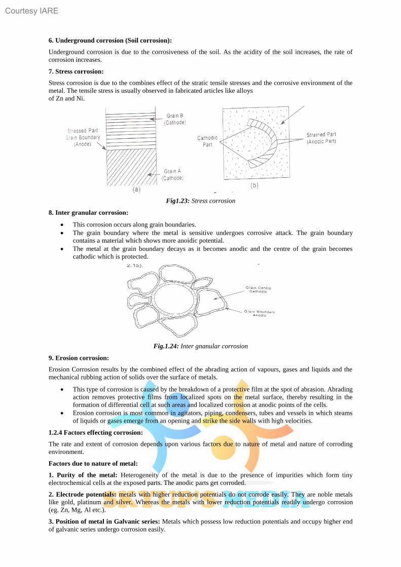
7. Stress corrosion:
Stress corrosion is due to the combines effect of the stratic tensile stresses and the corrosive environment of the
metal. The tensile stress is usually observed in fabricated articles like alloys
of Zn and Ni.
Fig1.23: Stress corrosion
8. Inter granular corrosion:
This corrosion occurs along grain boundaries.
The grain boundary where the metal is sensitive undergoes corrosive attack. The grain boundary
contains a material which shows more anoidic potential.
The metal at the grain boundary decays as it becomes anodic and the centre of the grain becomes
cathodic which is protected.
Fig.1.24: Inter gnanular corrosion
9. Erosion corrosion:
Erosion Corrosion results by the combined effect of the abrading action of vapours, gases and liquids and the
mechanical rubbing action of solids over the surface of metals.
This type of corrosion is caused by the breakdown of a protective film at the spot of abrasion. Abrading
action removes protective films from localized spots on the metal surface, thereby resulting in the
formation of differential cell at such areas and localized corrosion at anodic points of the cells.
Erosion corrosion is most common in agitators, piping, condensers, tubes and vessels in which steams
of liquids or gases emerge from an opening and strike the side walls with high velocities.
1.2.4 Factors effecting corrosion:
The rate and extent of corrosion depends upon various factors due to nature of metal and nature of corroding
environment.
Factors due to nature of metal:
1. Purity of the metal: Heterogeneity of the metal is due to the presence of impurities which form tiny
electrochemical cells at the exposed parts. The anodic parts get corroded.
2. Electrode potentials: metals with higher reduction potentials do not corrode easily. They are noble metals
like gold, platinum and silver. Whereas the metals with lower reduction potentials readily undergo corrosion
(eg. Zn, Mg, Al etc.).
3. Position of metal in Galvanic series: Metals which possess low reduction potentials and occupy higher end
of galvanic series undergo corrosion easily.
Courtesy IARE
22
Metals which possess high reduction potentials and occupy lower end of galvanic series do not undergo
corrosion and they get protected.
When two metals are in electrical contact in presence of an electrolyte, then the metal which is more
active undergoes corrosion.
The rate of corrosion depends on the difference in their position in galvanic series. Greater the
difference more will be the extent of corrosion at anode.
Ex: The potential difference between Fe and Cu is 0.78V which is more than that between Fe and Sn
(0.30V). Therefore, Fe corrodes faster when in contact with Cu than that with Sn. on this account, the
use of dissimilar metals should be avoided wherever possible (Ex: Bolt & nuts, screw & washer).
4. Relative areas of anodic and cathodic cells: the relative areas o of corrosion is influenced by cathodic to
anodic cells.
If the metal has small anodic and large cathodic area, the rate of corrosion is very high. This is because the
electrons are liberated at anode which is consumed at cathode. If the cathodic area is larger, the liberated
electrons are rapidly consumed at cathode. This further enhances the anodic reaction leading to increase the
rate of corrosion.
5. Hydrogen over voltage:
When a cathode reaction is hydrogen evolution type, the metal with Lower hydrogen over voltage on its
surface is more susceptible for corrosion, since the liberation of hydrogen gas is easy at this condition.
Hence the cathodic reaction is very fast which in turn Makes anodic reaction fast. Hence the rate of
corrosion increases. Higher the over voltage, lesser is the corrosion.
6. Physical state of metal:
Metals with small grain size have more tendencies to undergo corrosion. Metal with more stress/strain also
undergoes corrosion easily.
7. Nature of surface film:
If the corrosion product formed is more stable, insoluble and nonporous, it acts as protective layer and
prevents further corrosion (Eg. Ti, Al and Cr). If the corrosion product is porous, volatile and soluble, it
further enhances the corrosion (Fe, Zn and Mg).
Factors due to nature corrosive environment:
1. Temperature: the rate of corrosion reactions increases with increase in temperature.
2. Humidity in air: the moisture or humidity present in atmosphere furnishes water to the electrolyte which
is essential for setting up of an electrochemical cell. The oxide film formed has the tendency to absorb
moisture which creates another electrochemical cell.
3. Presence of impurities: Atmosphere is contaminated with gases like CO2, SO2, H2S; fumes of H2SO4,
HCl etc. and other suspended particles in the vicinity of industrial areas. They are Responsible for electrical
conductivity, thereby increasing corrosion.
4. pH value: pH value of the medium has the greater effect on corrosion. Acidic pH increases the rate of
corrosion.
5. Amount of oxygen in atmosphere: As the percentage of oxygen in atmosphere increases, the rate of
corrosion also increases due to the formation of oxygen concentration cell. The decay of metal occurs at the
anodic part and the cathodic part of the metal is protected.
1.2.5 Corrosion control methods:
I. Cathodic protection:
The method of protecting the base metal by making it to behave like a cathode is called as cathodic
protection.
There are two types of cathodic protection
(a) Sacrificial anode method
(b) Impressed current method.
a. Sacrificial anode method
In this protection method, the metallic structure to be protected (base metal) is connected by a wire to a
more anodic metal so that all the corrosion is concentrated at this more anodic metal.
The more anodic metal itself gets corroded slowly, while the parent structure (cathodic) is protected.
The more active metal so employed is called sacrificial anode. The corroded sacrificial anode is
replaced by a fresh one, when consumed completely.
Metals commonly employed as sacrificial anode are Mg, Zn, Al and their alloys which possess low
reduction potential and occupies higher end in electrochemical series.
Courtesy IARE
23
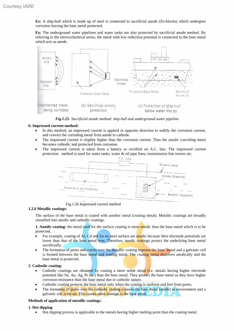
Ex: A ship-hull which is made up of steel is connected to sacrificial anode (Zn-blocks) which undergoes
corrosion leaving the base metal protected.
Ex: The underground water pipelines and water tanks are also protected by sacrificial anode method. By
referring to the electrochemical series, the metal with low reduction potential is connected to the base metal
which acts as anode.
Fig.1.25: Sacrificial anode method: ship hull and underground water pipeline
b. Impressed current method:
In this method, an impressed current is applied in opposite direction to nullify the corrosion current,
and convert the corroding metal from anode to cathode.
The impressed current is slightly higher than the corrosion current. Thus the anodic corroding metal
becomes cathodic and protected from corrosion.
The impressed current is taken from a battery or rectified on A.C. line. The impressed current
protection method is used for water tanks, water & oil pipe lines, transmission line towers etc.
Fig.1.26 Impressed current method
1.2.6 Metallic coatings:
The surface of the base metal is coated with another metal (coating metal). Metallic coatings are broadly
classified into anodic and cathodic coatings.
1. Anodic coating: the metal used for the surface coating is more anodic than the base metal which is to be
protected.
For example, coating of Al, Cd and Zn on steel surface are anodic because their electrode potentials are
lower than that of the base metal iron. Therefore, anodic coatings protect the underlying base metal
sacrificially.
The formation of pores and cracks over the metallic coating exposes the base metal and a galvanic cell
is formed between the base metal and coating metal. The coating metal dissolves anodically and the
base metal is protected.
2. Cathodic coating:
Cathodic coatings are obtained by coating a more noble metal (i.e. metals having higher electrode
potential like Sn, Au, Ag, Pt etc.) than the base metal. They protect the base metal as they have higher
corrosion resistance than the base metal due to cathodic nature.
Cathodic coating protects the base metal only when the coating is uniform and free from pores.
The formation of pores over the cathodic coating exposes the base metal (anode) to environment and a
galvanic cell is set up. This causes more damage to the base metal.
Methods of application of metallic coatings:
1. Hot dipping
Hot dipping process is applicable to the metals having higher melting point than the coating metal.
Courtesy IARE
24
It is carried out by immersing a well cleaned base metal in a bath containing molten coating metal and
a flux layer.
The flux cleans the surface of the base metal and prevents the oxidation of the molten coating metal.
Ex: Coating of Zn, Pb, Al on iron and steel surfaces.
The most widely used hot dipping processes are galvanizing and tinning.
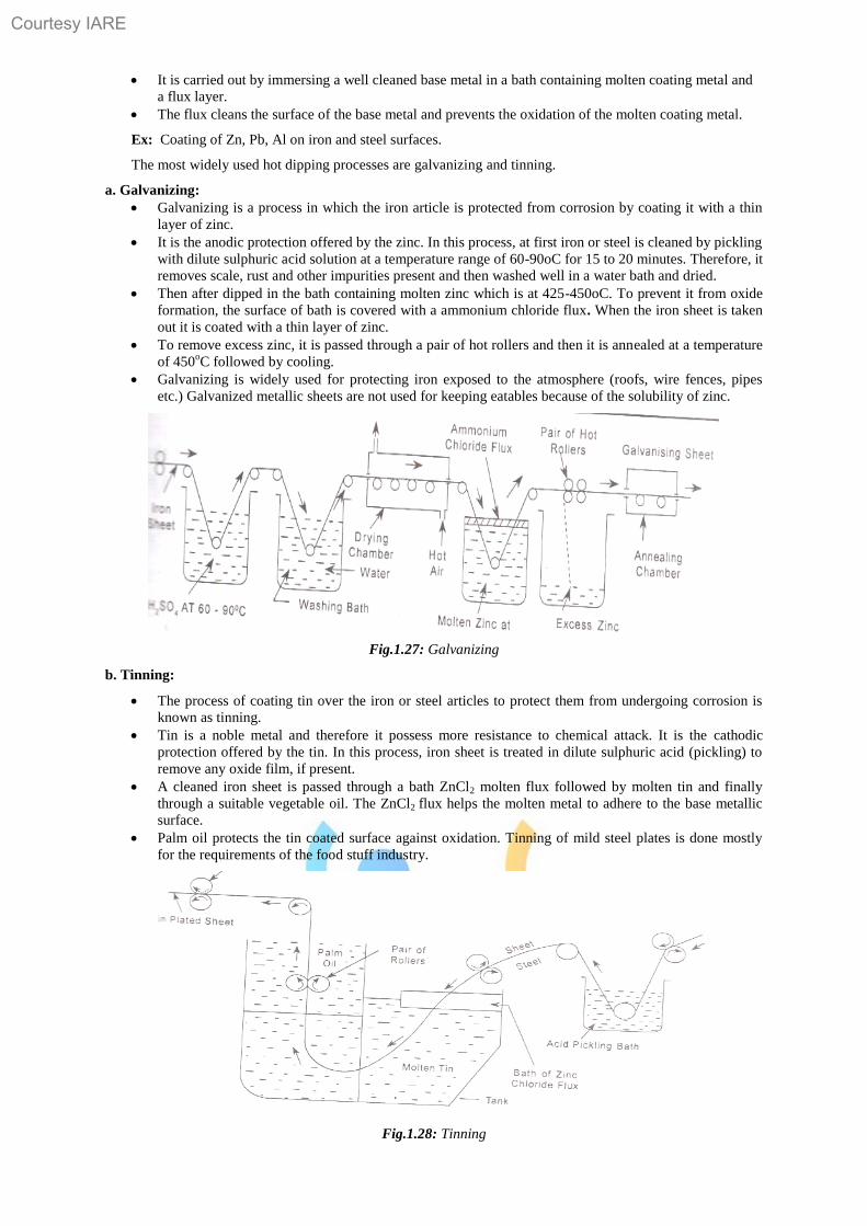
a. Galvanizing:
Galvanizing is a process in which the iron article is protected from corrosion by coating it with a thin
layer of zinc.
It is the anodic protection offered by the zinc. In this process, at first iron or steel is cleaned by pickling
with dilute sulphuric acid solution at a temperature range of 60-90oC for 15 to 20 minutes. Therefore, it
removes scale, rust and other impurities present and then washed well in a water bath and dried.
Then after dipped in the bath containing molten zinc which is at 425-450oC. To prevent it from oxide
formation, the surface of bath is covered with a ammonium chloride flux. When the iron sheet is taken
out it is coated with a thin layer of zinc.
To remove excess zinc, it is passed through a pair of hot rollers and then it is annealed at a temperature
of 450oC followed by cooling.
Galvanizing is widely used for protecting iron exposed to the atmosphere (roofs, wire fences, pipes
etc.) Galvanized metallic sheets are not used for keeping eatables because of the solubility of zinc.
Fig.1.27: Galvanizing
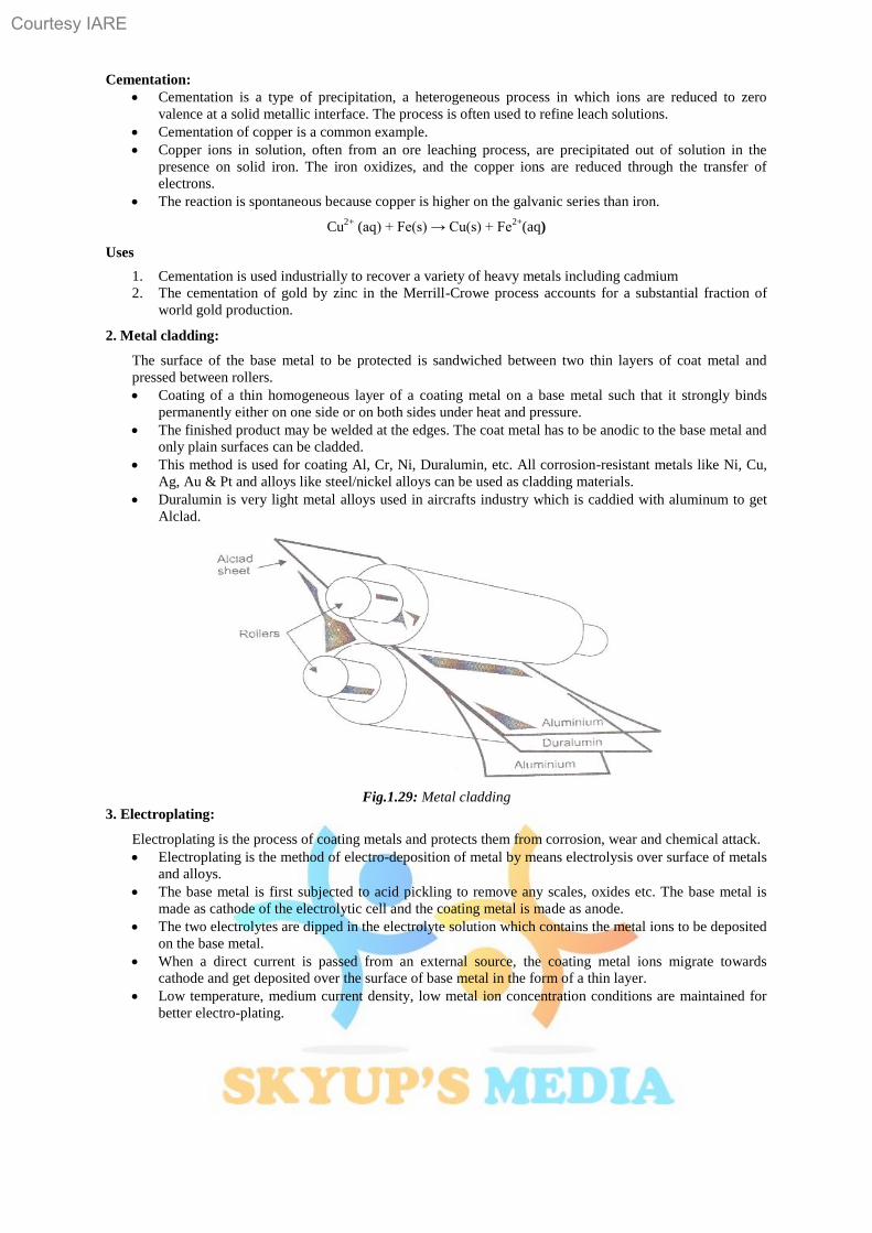
b. Tinning:
The process of coating tin over the iron or steel articles to protect them from undergoing corrosion is
known as tinning.
Tin is a noble metal and therefore it possess more resistance to chemical attack. It is the cathodic
protection offered by the tin. In this process, iron sheet is treated in dilute sulphuric acid (pickling) to
remove any oxide film, if present.
A cleaned iron sheet is passed through a bath ZnCl2 molten flux followed by molten tin and finally
through a suitable vegetable oil. The ZnCl2 flux helps the molten metal to adhere to the base metallic
surface.
Palm oil protects the tin coated surface against oxidation. Tinning of mild steel plates is done mostly
for the requirements of the food stuff industry.
Fig.1.28: Tinning
Courtesy IARE
25
Cementation:
Cementation is a type of precipitation, a heterogeneous process in which ions are reduced to zero
valence at a solid metallic interface. The process is often used to refine leach solutions.
Cementation of copper is a common example.
Copper ions in solution, often from an ore leaching process, are precipitated out of solution in the
presence on solid iron. The iron oxidizes, and the copper ions are reduced through the transfer of
electrons.
The reaction is spontaneous because copper is higher on the galvanic series than iron.
Cu2+
(aq) + Fe(s) → Cu(s) + Fe2+
(aq)
Uses
1. Cementation is used industrially to recover a variety of heavy metals including cadmium
2. The cementation of gold by zinc in the Merrill-Crowe process accounts for a substantial fraction of
world gold production.
2. Metal cladding:
The surface of the base metal to be protected is sandwiched between two thin layers of coat metal and
pressed between rollers.
Coating of a thin homogeneous layer of a coating metal on a base metal such that it strongly binds
permanently either on one side or on both sides under heat and pressure.
The finished product may be welded at the edges. The coat metal has to be anodic to the base metal and
only plain surfaces can be cladded.
This method is used for coating Al, Cr, Ni, Duralumin, etc. All corrosion-resistant metals like Ni, Cu,
Ag, Au & Pt and alloys like steel/nickel alloys can be used as cladding materials.
Duralumin is very light metal alloys used in aircrafts industry which is caddied with aluminum to get
Alclad.
Fig.1.29: Metal cladding
3. Electroplating:
Electroplating is the process of coating metals and protects them from corrosion, wear and chemical attack.
Electroplating is the method of electro-deposition of metal by means electrolysis over surface of metals
and alloys.
The base metal is first subjected to acid pickling to remove any scales, oxides etc. The base metal is
made as cathode of the electrolytic cell and the coating metal is made as anode.
The two electrolytes are dipped in the electrolyte solution which contains the metal ions to be deposited
on the base metal.
When a direct current is passed from an external source, the coating metal ions migrate towards
cathode and get deposited over the surface of base metal in the form of a thin layer.
Low temperature, medium current density, low metal ion concentration conditions are maintained for
better electro-plating.
Courtesy IARE
26
Fig1.30: Electroplating
Electro less plating (Ni plating): is an auto-catalytic chemical technique used to deposit a Layer of nickel-
phosphorus or nickel-boron alloy on a solid work piece, such as metal or plastic. The process relies on the
presence of a reducing agent,
For example hydrated sodium hypophosphite (NaPO2H2·H2O) which reacts with the metal ions to
deposit metal.
The alloys with different percentage of phosphorus, ranging from 2-5 (low phosphorus) to up to 11-14
(high phosphorus) are possible. The metallurgical properties of alloys depend on the percentage of
phosphorus.
Electro less nickel plating is an auto-catalytic reaction used to deposit a coating of nickel on a
substrate. Unlike electroplating, it is not necessary to pass an electric current through the solution to
form a deposit.
This plating technique is to prevent corrosion and wear. EN techniques can also be used to manufacture
composite coatings by suspending powder in the bath.
Advantages of Electro less plating:
1. Does not use electrical power.
2. Even coating on parts surface can be achieved.
3. No sophisticated jigs or racks are required.
4. There is flexibility in plating volume and thickness.
5. The process can plate recesses and blind holes with stable thickness.
6. Chemical replenishment can be monitored automatically.
7. Complex filtration method is not required
8. Matte, Semi Bright or Bright finishes can be obtained.
Disadvantages of Electro less plating
1. Lifespan of chemicals is limited.
2. Waste treatment cost is high due to the speedy chemical renewal.
Applications:
1. The most common form of electro less nickel plating produces a nickel phosphorus alloy coating. The
phosphorus content in electro less nickel coatings can range from 2% to 13%.
2. It is commonly used in engineering coating applications where wear resistance, hardness and corrosion
protection are required.
3. Applications include oil field valves, rotors, drive shafts, paper handling equipment, fuel rails, .optical
surfaces for diamond turning, door knobs, kitchen utensils, bathroom fixtures, electrical/mechanical
tools and office equipment
4. It is also commonly used as a coating in electronics printed circuit board manufacturing, typically with
an overlay of gold to prevent corrosion. This process is known as electroless nickel immersion gold.
5. 5 It is also used extensively in the manufacture of hard disk drives, as a way of providing an atomically
smooth coating to the aluminum disks, the magnetic layers are then deposited on top of this film.
1.2.7 Surface coatings:
The application of surface coating is the common method to protect the surface of the metal from the
corroding environment. These surface coatings exhibit chemical inertness to corrosive environment,
adhesive properties and impermeable.
Courtesy IARE
27
a. Organic surface coatings:
Organic surface coatings are applied over the metallic surfaces to prevent from the corrosion.
Properties of Organic surface coatings.
Chemical inertness to the corrosive environment
Good surface adhesion
Impermeability to water, gases and salts
Eg. Paints
Paint is a mechanical dispersion mixture of several constituents in a vehicle oil or drying oil.
The following are the constituents of paints and their functions.
Constituent Functions Examples:
1. Pigment
It is a major constituent of the paint.
Provides desired colour to the paint
It protects the paint by reflecting harmful U.V radiation.
Gives strength and increases weather resistance of the film.
White- white lead, ZnO
Red- Red lead,
Ferric oxide
2. Vehicle oil/ Drying oil:
It forms the film forming constituent of the paint.
It acts as medium for the dispersion of various constituents.
It gives durability, adhesion and water proofness to the paint.
Sunflower oil, Mustard oil, Soya bean oil.
3. Thinners:
Reduces the viscosity and increases the elasticity of the
Paint film.
Enhances the dissolving the additives in vehicle medium. Turpentine, Kerosene, Naphtha.
4. Driers:
Driers are oxygen carrying catalysts.
They accelerate the drying of the paint film throughoxidation, polymerization and condensation.
Tunstates and nahthalates of Pb, Zn and Co.
5. Extenders/ Fillers:
Low refractive indices materials.
They reduce the cost and cracking nature of the paint film.
BaSO4, gypsum,
6. Plasticizers:
They provide elasticity to the film and minimize cracking.
Tributylphosphate,
Triphenylphosphate
7. Anti skinning agents:
They prevent the gelling nature the paint film.
Polyhydroxy phenols
Courtesy IARE
28
UNIT-II
Engineering Material
INDEX
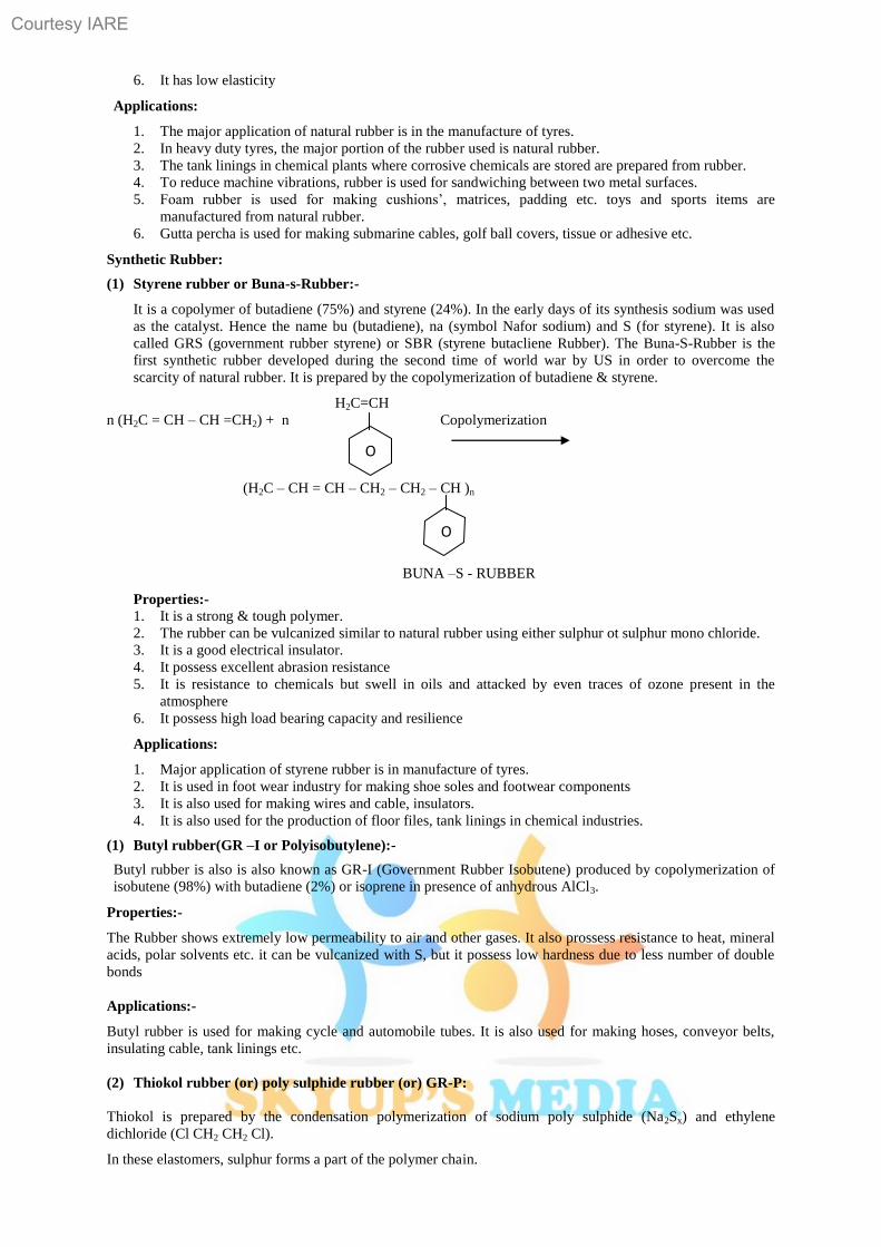
2.1 Polymers
2.1.1 Types of polymerization
2.1.2 Mechanism (chain growth & step growth)
2.1.3 Plastics (Thermoplastic & Thermosetting resin)
2.1.4 Compounding & fabrication of plastics
2.1.5 Chemistry of some important thermoplastic & thermo set Resins
2.1.6 Conducting polymers
2.1.7 Liquid crystal polymers
2.1.8 Rubber Natural Rubber, Vulcanization
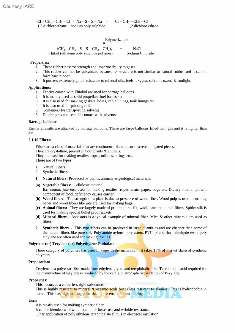
2.1.9 Elastomers – Buna – S, Butyl Rubber, Thiokol Rubbers
2.1.10 Fibers
2.1.11 FRP, applications
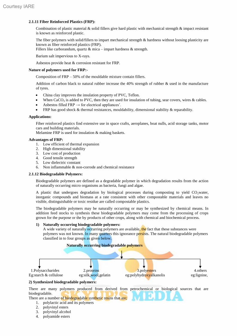
2.1.12 Bio-degradable Polymers
2.2 Material Chemistry
2.2.1 Cement
2.2.2 Lubricants
2.2.3. Refractories
2.2.4 Nanomaterials
Courtesy IARE
29
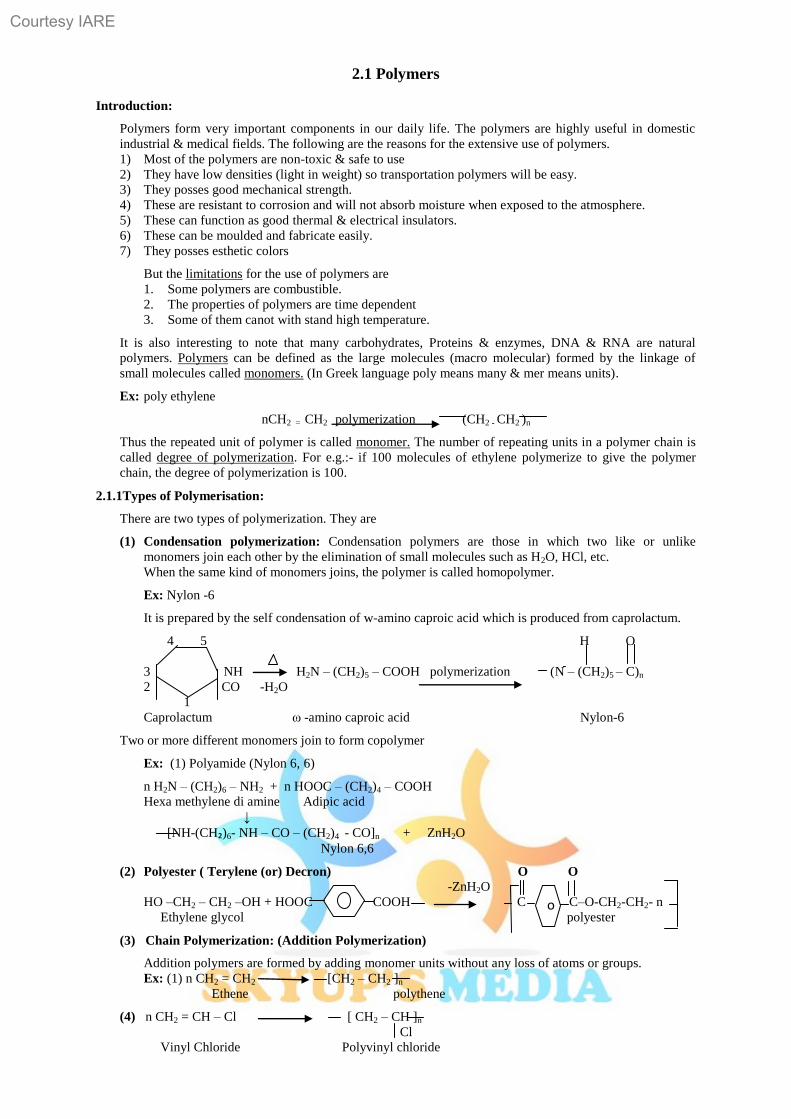
2.1 Polymers
Introduction:
Polymers form very important components in our daily life. The polymers are highly useful in domestic
industrial & medical fields. The following are the reasons for the extensive use of polymers.
1) Most of the polymers are non-toxic & safe to use
2) They have low densities (light in weight) so transportation polymers will be easy.
3) They posses good mechanical strength.
4) These are resistant to corrosion and will not absorb moisture when exposed to the atmosphere.
5) These can function as good thermal & electrical insulators.
6) These can be moulded and fabricate easily.
7) They posses esthetic colors
But the limitations for the use of polymers are
1. Some polymers are combustible.
2. The properties of polymers are time dependent
3. Some of them canot with stand high temperature.
It is also interesting to note that many carbohydrates, Proteins & enzymes, DNA & RNA are natural
polymers. Polymers can be defined as the large molecules (macro molecular) formed by the linkage of
small molecules called monomers. (In Greek language poly means many & mer means units).
Ex: poly ethylene
nCH2 = CH2 polymerization (CH2 - CH2 )n
Thus the repeated unit of polymer is called monomer. The number of repeating units in a polymer chain is
called degree of polymerization. For e.g.:- if 100 molecules of ethylene polymerize to give the polymer
chain, the degree of polymerization is 100.
2.1.1Types of Polymerisation:
There are two types of polymerization. They are
(1) Condensation polymerization: Condensation polymers are those in which two like or unlike
monomers join each other by the elimination of small molecules such as H2O, HCl, etc.
When the same kind of monomers joins, the polymer is called homopolymer.
Ex: Nylon -6
It is prepared by the self condensation of w-amino caproic acid which is produced from caprolactum.
4 5 H O
3 NH H2N – (CH2)5 – COOH polymerization (N – (CH2)5 – C)n
2 CO -H2O
1
Caprolactum ω -amino caproic acid Nylon-6
Two or more different monomers join to form copolymer
Ex: (1) Polyamide (Nylon 6, 6)
n H2N – (CH2)6 – NH2 + n HOOC – (CH2)4 – COOH
Hexa methylene di amine Adipic acid
↓
[NH-(CH₂)6- NH – CO – (CH2)4 - CO]n + ZnH2O
Nylon 6,6
(2) Polyester ( Terylene (or) Decron) O O
-ZnH2O
HO –CH2 – CH2 –OH + HOOC COOH C C–O-CH2-CH2- n
Ethylene glycol polyester
(3) Chain Polymerization: (Addition Polymerization)
Addition polymers are formed by adding monomer units without any loss of atoms or groups.
Ex: (1) n CH2 = CH2 [CH2 – CH2 ]n
Ethene polythene
(4) n CH2 = CH – Cl [ CH2 – CH ]n
Cl
Vinyl Chloride Polyvinyl chloride
o
Courtesy IARE
30
2.1.2 Mechanism of chain growth polymerization:
Additional polymerization classified into
(1) Free radical polymerization
(2) Cationic additional polymerization
(3) Anionic additional polymerization
(4) Coordination polymerization
These free radical, cation & anion are characterized by initiation, propagation & termination steps.
Difference between condensation of additional polymerisation:-
Condensation polymerisation Additional polymerisation
(1) It is also known as step growth polymerisation (1) It is also known as chain growth
polymerization
(2) It takes place in monomers having reactive
functional groups
(2) It takes place only in monomers having
multiple bonds.
(3) It takes place with elimination of simple
molecule like H2O,NH3,HCl etc.,
(3) It takes place without elimination of simple
molecule.
(4) Repeat units of monomers are different (4) Repeat units & monomers are same.
(5) The polymer is formed in gradual steps (5) Reaction is fast and polymer is formed at once.
(6) The molecular mass of polymer increases
throughout the reaction
(6) There is very little change in the molecular
mass throughout the reaction
(7) Product obtained may be
thermosetting/thermoplastic (7) Product obtained are thermoplastic
(8) E.g.:- Bakelite, polyester ,polyamides etc., (8) E.g:-Polyethylene, PVC, poly styrene.
2.1.3 Plastics: Plastic is a substance that can be easily formed or moulded into a desired shape.
Plastic can be formed in a desired shape by the effect of mechanical force & heat.
In the manufacture of plastic raw materials like coal, petroleum, cellulose, salt, sulphur, limestone, air, water etc
are used.
Plastics as engineering materials:
Advantages of plastics over other engineering materials.
(1) Low fabrication cost, low thermal & electrical conductivities, high resistance to corrosion & solvents.
(2) The stress – strain relationship of plastics is similar to that of the metals.
(3) Plastics reduce noise & vibration in machines
(4) Plastics are bad conductors of heat are useful for making handles used for hot objects, most plastics are
inflammable.
(5) Plastics are electrical insulators & find large scale use in the electrical industry.
(6) Plastics are resistance to chemicals.
(7) Plastics are clear & transparent so they can be given beautiful colours.
Types of Plastic:
(1) Thermoplastics
(2) Thermosetting plastics.
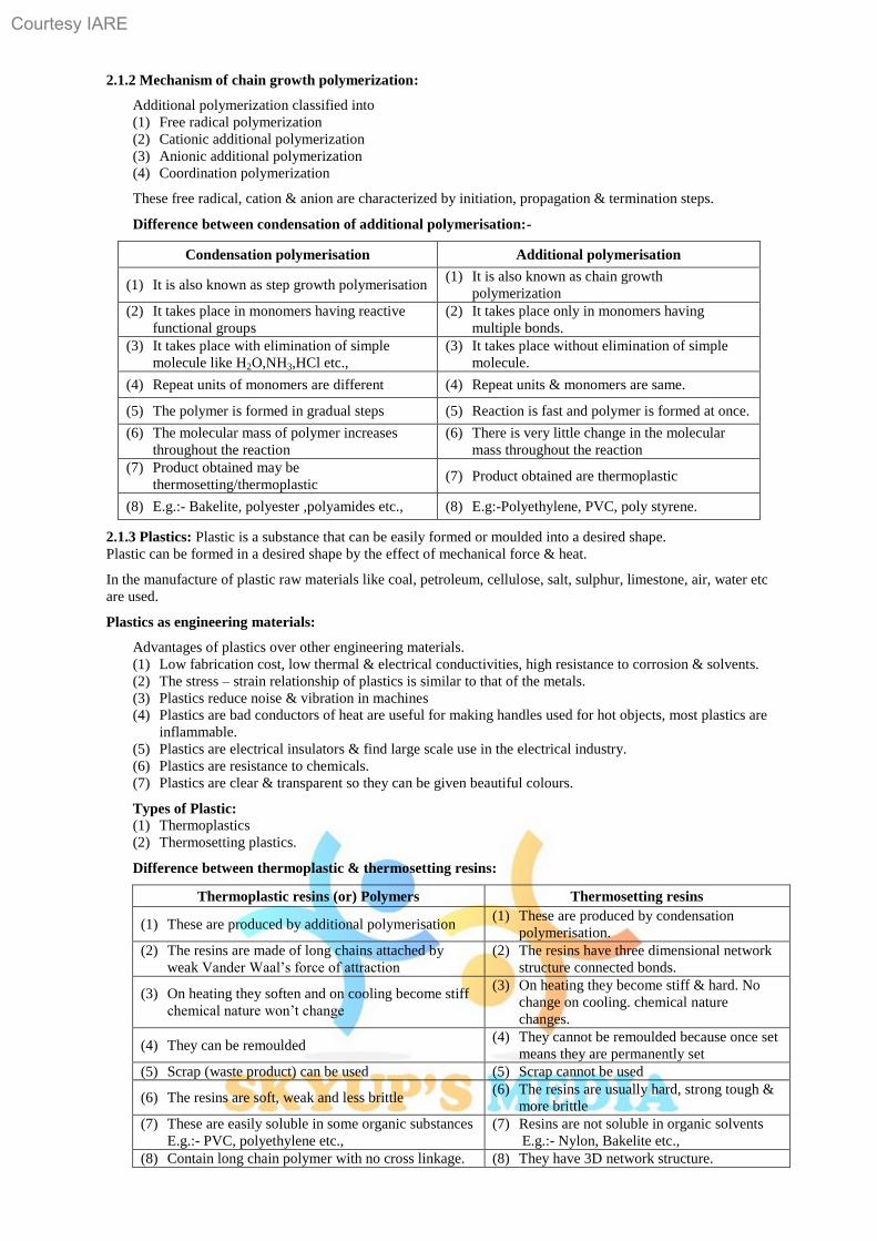
Difference between thermoplastic & thermosetting resins:
Thermoplastic resins (or) Polymers Thermosetting resins
(1) These are produced by additional polymerisation (1) These are produced by condensation
polymerisation.
(2) The resins are made of long chains attached by
weak Vander Waal‟s force of attraction
(2) The resins have three dimensional network
structure connected bonds.
(3) On heating they soften and on cooling become stiff
chemical nature won‟t change
(3) On heating they become stiff & hard. No
change on cooling. chemical nature
changes.
(4) They can be remoulded (4) They cannot be remoulded because once set
means they are permanently set
(5) Scrap (waste product) can be used (5) Scrap cannot be used
(6) The resins are soft, weak and less brittle (6) The resins are usually hard, strong tough &
more brittle
(7) These are easily soluble in some organic substances
E.g.:- PVC, polyethylene etc.,
(7) Resins are not soluble in organic solvents
E.g.:- Nylon, Bakelite etc.,
(8) Contain long chain polymer with no cross linkage. (8) They have 3D network structure.
Courtesy IARE
31
2.1.4 Compounding & Fabrication of plastics:
Compounding of plastics:- Compounding of plastics may be defined as the mixing of different materials
like plasticizers, fillers of extenders, lubricants, pigments to the thermoplastic & thermosetting resins to
increase their useful properties like strength, toughness, etc.
Resin have plasticity or binding property, but need other ingredients to be mixed with them for fabrication
into useful shapes.
Ingredients used in compounding o plastics are
(1)Resins (2) Plasticizers (3) fillers (4) pigments (5) Stabilizers.
(1) Resins:- The product of polymerisation is called resins and this forms the major portion of the body of
plastics. It is the binder, which holds the different constituents together. Thermosetting resins are
usually, supplied as linear – polymers of comparatively low molecular weight, because at this stage
they are fusible and hence, mouldable. The conversion of this fusible form into cross-linked infusible
form takes place, during moulding itself, in presence of catalysts etc.
(2) Plasticizers:- Plasticizers are substances added to enhance the plasticity of the material and to reduce
the cracking on the surface.
Plasticizers are added to the plastics to increase the flexibility & toughness. Plasticizers also increase
the flow property of the plastics.
Ex: Tricresyl phosphate, Dibutyle oxalate, castor oil.
(3) Fillers (or) extenders:- Fillers are generally added to thermosetting plastics to increase elasticity and
crack resistance.
Fillers improve thermal stability, strength, non combustibility, water resistance, electrical insulation
properties & external appearance.
Ex: Mica, cotton, carbon black, graphite, BaSO4 etc.
(4) Dyes and pigments:- These are added to impart the desired colour to the plastics and give decorative
effect.
Ex: Lead chromate (yellow), ferro cyanide (blue)
(5) Stabilizers:- Stabilizers are used to improve the thermal stability of plastics, e.g.:- PVC. At moulding
temperature, PVC undergoes decomposition & decolourisation. So during their moulding, stabilizers
are used. E.g.:- white lead, head chromate.
Fabrication of plastics:- many methods of fabricating plastics into desired shaped articles are
employed. This production of plastics is known as fabrication of plastics.
The methods, usually depends upon the types of resins used i.e., whether thermosetting or
thermoplastic.
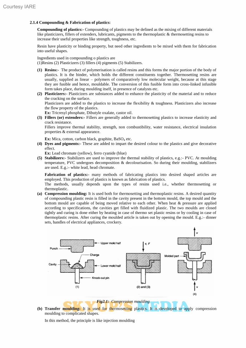
(a) Compression moulding: It is used both for thermosetting and thermoplastic resins. A desired quantity
of compounding plastic resin is filled in the cavity present in the bottom mould, the top mould and the
bottom mould are capable of being moved relative to each other. When heat & pressure are applied
according to specifications, the cavities get filled with fluidized plastic. The two moulds are closed
tightly and curing is done either by heating in case of thermo set plastic resins or by cooling in case of
thermoplastic resins. After curing the moulded article is taken out by opening the mould. E.g.:- dinner
sets, handles of electrical appliances, crockery.
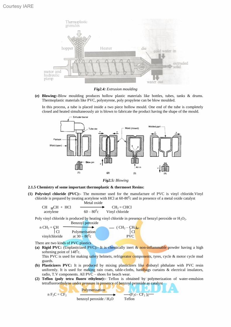
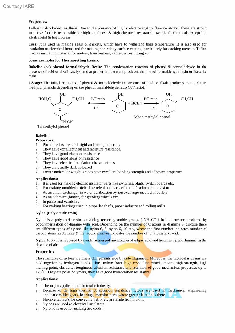
Fig2.1: Compression moulding
(b) Transfer moulding: It is used for thermosetting plastics. It is developed to apply compression
moulding to complicated shapes.
In this method, the principle is like injection moulding
Courtesy IARE
32
The moulding powder is heated in a chamber to become plastic. Later it is injected in to a mould by
plunger working at high pressure through orifice. Due to this heat is developed and the plastic melts,
takes the shape of the mould.
Fig-2.2: Transfer moulding
(c) Injection moulding: It is used for thermoplastic resins. The moulded plastic powder is heated in a
cylinder and injected at a controlled rate into the locked mould by means of screw arrangement.
The mould is kept cold so that the hot plastic becomes solid due to the phenomenon of curing. After
sufficient curing, the mould is opened to allow the ejection of moulded object.
Ex: bottle caps, pocket combs, containers etc.
The advantage of this process is a high rate of production.
Fig2.3: Injection moulding
(d) Extrusion moulding:- Extrusion moulding is used for moulding of thermoplastic materials into
articles of uniform cross section like tubes, rods, sheets, wires, cables etc. The thermoplastic
ingredients are heated to plastic state (semi solid state) and then pushed by means of a screw conveyer
into a die, having the required outer shape of the article to be fabricated. The extruded article gets
cooled due to atmosphere exposure or artificially by air jets or by water sprayer in a long conveyor
which carries away the cooled product.
Courtesy IARE
33
Fig2.4: Extrusion moulding
(e) Blowing:-Blow moulding produces hollow plastic materials like bottles, tubes, tanks & drums.
Thermoplastic materials like PVC, polystyrene, poly propylene can be blow moulded.
In this process, a tube is placed inside a two piece hollow mould. One end of the tube is completely
closed and heated simultaneously air is blown to fabricate the product having the shape of the mould.
Fig2.5: Blowing
2.1.5 Chemistry of some important thermoplastic & thermoset Resins:
(1) Polyvinyl chloride (PVC):- The monomer used for the manufacture of PVC is vinyl chloride.Vinyl
chloride is prepared by treating acetylene with HCl at 60-800c and in presence of a metal oxide catalyst
Metal oxide
CH CH + HCl CH2 = CHCl
acetylene 60 – 800c Vinyl chloride
Poly vinyl chloride is produced by heating vinyl chloride in presence of benzyl peroxide or H2O2.
Benzoyl peroxide
n CH2 = CH ( CH2 – CH )n
Cl Polymerisation Cl
vinylchloride at 30 – 800c PVC
There are two kinds of PVC plastics
(a) Rigid PVC: (Unplasticized PVC):- It is chemically inert & non-inflammable powder having a high
softening point of 1480c.
This PVC is used for making safety helmets, refrigerator components, tyres, cycle & motor cycle mud
guards.
(b) Plasticizers PVC: It is produced by mixing plasticizers like disbutyl phthalate with PVC resin
uniformly. It is used for making rain coats, table-cloths, handbags curtains & electrical insulators,
radio, T.V components. All PVC – shoes for beach wear.
(2) Teflon (poly tetra fluoro ethylene):- Teflon is obtained by polymerization of water-emulsion
tetrafluoroethylene under pressure in presence of benzoyl peroxide as catalyst
Polymerisation
n F2C = CF2 (F2c– CF2 )n
benzoyl peroxide / H2O Teflon
Courtesy IARE
34
Properties:
Teflon is also known as fluon. Due to the presence of highly electronegative fluorine atoms. There are strong
attractive force is responsible for high toughness & high chemical resistance towards all chemicals except hot
alkali metal & hot fluorine.
Uses: It is used in making seals & gaskets, which have to withstand high temperature. It is also used for
insulation of electrical items and for making non-sticky surface coating, particularly for cooking utensils. Teflon
used as insulating material for motors, transformers, cables, wires, fitting etc.
Some examples for Thermosetting Resins:
Bakelite (or) phenol formaldehyde Resin: The condensation reaction of phenol & formaldehyde in the
presence of acid or alkali catalyst and at proper temperature produces the phenol formaldehyde resin or Bakelite
resin.
I Stage: The initial reactions of phenol & formaldehyde in presence of acid or alkali produces mono, cli, tri
methylol phenols depending on the phenol formaldehyde ratio (P/F ratio).
OH OH OH
HOH2C CH2OH P/F ratio P/F ratio CH2OH
+ HCHO
1:3 1:1
Mono methylol phenol
CH₂OH
Tri methylol phenol
Bakelite
Properties: 1. Phenol resins are hard, rigid and strong materials
2. They have excellent heat and moisture resistance.
3. They have good chemical resistance
4. They have good abrasion resistance
5. They have electrical insulation characteristics
6. They are usually dark coloured
7. Lower molecular weight grades have excellent bonding strength and adhesive properties.
Applications:
1. It is used for making electric insulator parts like switches, plugs, switch boards etc.
2. For making moulded articles like telephone parts cabinet of radio and television
3. As an anion exchanger in water purification by ion exchange method in boilers
4. As an adhesive (binder) for grinding wheels etc.,
5. In paints and varnishes
6. For making bearings used in propeller shafts, paper industry and rolling mills
Nylon (Poly amide resin):
Nylon is a polyamide resin containing recurring amide groups (-NH CO-) in its structure produced by
copolymerization of diamine with acid. Depending on the number of C atoms in diamine & dioxide there
are different types of nylons like nylon 6, 6, nylon 6, 10 etc., where the first number indicates number of
carbon atoms in diamine & the second number indicates the number of „c‟ atoms in diacid.
Nylon 6, 6:- It is prepared by condensation polymerization of adipic acid and hexamethylene diamine in the
absence of air.
Properties:
The structures of nylons are linear that permits side by side alignment. Moreover, the molecular chains are
held together by hydrogen bonds. Thus, nylons have high crystalline which imparts high strength, high
melting point, elasticity, toughness, abrasion resistance and retention of good mechanical properties up to
1250C. They are polar polymers, they have good hydrocarbon resistance.
Applications:
1. The major application is in textile industry.
2. Because of its high thermal & abrasion resistance nylons are used in mechanical engineering
applications like gears, bearings, machine parts where greater friction is there.
3. Flexible tubing‟s for conveying petrol etc are made from nylons
4. Nylons are used as electrical insulators.
5. Nylon 6 is used for making tire cords.
O O O
Courtesy IARE
35
6. Nylons are used in automobile industry and telecommunication industry for making radiator parts and
coil formers respectively.
2.1.6 Conducting polymers:-
A polymer which can conduct electricity is termed as conducting polymer. It is classified into following
types.
Conducting polymers
Intrinsically conducting Extrinsically conducting
Polymers polymers
Conducting polymers Doped conductive element Blended
Having conjugation conducting polymers filled polymers conducting polymers
(A) Intrinsically conducting polymers:
These polymers have extensive conjugation in the backbone which is responsible for conductance.
(1) Conducting polymers having conjugation ∏-e-s in the back bone:-
Polymers have alternating double and single bond along the polymer chain and each carbon atom is in
sp2 hybridized state. One valence e
-(∏) on carbon is Pz orbital. The orbitals of conjugated (∏) e
-s
overlap the entire backbone of the polymer and result in the formation of valence bonds & conducting
bands.
The valence band is filled band and conduction band is empty. When the energy gap between these is
low, the e-s from valence band are excited to conduction band become mobile throughout the polymer
and show conductivity.
Ex: conjugated polymers
n CH = CH polymerization ( CH = CH )n
Acetylene Poly acetylene
Trans structure of polyacetylene
(2) Doped conducting polymers:
The conducting polymers having ∏ e-s in their backbone can easily be oxidized or reduced because they
possess low ionization potential and high electron affinities. Hence their conductance can be increased by
introducing a positive charge or negative charge on polymer backbone by oxidation or reduction. This process
is similar to semiconductor technology and is called doping. Doping is again two types.
1. Creating a positive site on polymer backbone called p-doping.
2. Creating a negative site on the polymer backbone called n-doping.
Oxidation process undergoes by adding some alkali metals or e- acceptor conducting is enhanced by p-
doping. Reduction process undergoes by adding reducing agents of electron donor conductivity is
enhanced by n-doping.
(B) Extrinsically conducting polymers:-
The conductivity of these polymers is due to the presence of externally added ingredients in them.
Again these polymers are two types.
(1) Conducting element filled polymers:-
The polymers acting as a binder to hold the conducting element such as carbon black, metallic fibers,
metallic oxides etc., minimum concentration of filler is added so that the polymer starts conducting. This
minimum concentration of conductive filler is called percolation threshold. At this concentration of filler, a
conducting path is formed in polymeric material. The most preferred filler is the special conducting grade c-
black has very surface area, more porosity and more of filamentous properties.
Advantages: 1. These polymers are low cost polymers
2. They are light in weight and mechanically durable.
3. These polymers are strong with good bulk conductivity.
4. They are fabricated very easily to any design.
(2) Blended conducting polymers: These are the polymers, which are obtained by mixing a non-
conducting polymer with a conducting polymer either physically or chemically. These blended
conducting polymers have better physical, chemical and mechanical properties.
Courtesy IARE
36
Applications of conducting polymers:
1. The conducting polymers are used in rechargeable batteries, small in size (botton size), producing
current density up to 50mA/cm2
2. Conducting polymers are also used for making analytical sensors for O2, NOx,SO2,NH3 and glucose
3. The conducting polymers are used for making ion exchangers. These membranes made of conducting
polymers show selective permeability for ions and gases hence they are used for control release of
drug.
4. The conducting polymers are used making electronic displays and optical fibres
5. They are used for cancer chemotherapy
6. The conducting polymers are applicable in photovoltaic devices. LED‟s and data storage.
The role of poly acetylenes as conducting polymers:-
The conjugated polymer with simplest chemical structure is poly acetylene. Polymerization of acetylene
with Zeigler Natta catalysts gibes poly acetylene which in its used form with increasing temperature gets
transformed to more stable transform.
This polymer is infusible, insoluble and becomes brittle on exposer to air.
The conductivity of poly acetylene is magnified by doping.
Exposure of the film to dry ammonia gives polymer with conductivity of 103Scm
-1, controlled addition of p-
doing agents like AgF5, Br2, I2, or HClO4 could move to still higher conductivities.
H H H H H H
C C C C C C
C C C C C
H H H H H
Conducting Mechanism:-
The semi conducting poly acetylene has a typical carbon back bone structure.
The localized e-s in „S‟ bonds form the back bone of the polymer chain and dominate the medicinal properties,
while the e-s in the ∏ bonds are delocalized along the chain and responsible for the electrical & optical
properties of a conjugated polymer.
The σ bonds form completely filled low lying energy bands that have larger energy gap than the ∏ bond e-s.
Before passing current, the e-s can flow along the molecules and one or more e
-s have to be removed or inserted.
In presence of an electric field, the e-s constituting ∏ bonds can move along the molecular chain.
The conductivity of the polymeric material, containing many chains of polymers will be limited by the fact that
the e-s have to jump from one molecules to the next. Hence the chains have to be packed in an ordered row.
Doping of polyacetylene:-
Polyacetylene possesses alternate single and double bonds that give rise to mobile ∏-e-s when doped, i.e.,
become anisotropic metallic conductors.
There are two types of doping, oxidation or reduction.
They are:
1. Oxidation with halogen (p-doping)
2. Reduction with alkali (n-doping).
Preparation of polyaniline:
Polyaniline is prepared by the redox polymerization of aniline in protonic and aqueous solution in the
presence of ammonium per disulphate as oxidant.
It can be regarded as conducting polymer under certain stimulating conditions like UV light, heat or
addition of a suitable dopant to the polymer.
Doping of polyaniline:
It can be made conductive by p-type doping or n-type doping of polymer.
In undoped state, it is a poor semi-conductor.
On doping with dopant para-hydroxy benzene sulphonic acid, its conductivity is increased by a factor of
10dm-1
/cm or more and forms polaron/bipolaron structure.
The conductivity µ of a conducting poly-aniline is related to number of charge carriers „n‟ and their
mobility µ.
Courtesy IARE
37
Properties:
Due to the presence of extended σ – bond system of conjugated polymers. It is highly susceptible to
chemical & electrochemical oxidation or reduction.
Electronically conducting polymers are extensively conjugated molecules and possess specially delocalized
band line structure.
Disadvantages:-
1. Polyaniline decomposes prior to melting. Hence it is difficult to process.
2. It is insoluble in common solvents except strong acid
3. It has poor mechanical properties.
Applications:-
Polyaniline is used for corrosion protection, sensors, smart windows, printed circuit boards, conductive
fabrics and conductive pipes fire explosives.
2.1.8 Natural Rubber:-
Natural Rubber is a high molecular weight hydrocarbon polymer represented by the formula (C5H8)x. it is
obtained from a milk emulsion called latex by tapping the bark of the tree. “Hevea brasiliensis”. It is a
polymer of isoprene units.
H
n H2C = C – CH = CH2 Polymerisation (H2C – C = C – CH2 )n
CH3 CH3
Isoprene Natural Rubber
The polymer chain of natural rubber is made of 2000 to 3000 monomer units.
Processing of Natural Rubber:-
By cutting the bark of rubber tree the milky colloidal rubber milk is obtained. The main constituent of rubber
latex is 25-45% of rubber and the remaining are water, protein & resinous materials. The rubber latex is
coagulated by using 5% acetic acid and made in to sheets. The rubber sheets are cured under mild heat and then
subjected to further processing.
Crepe rubber:-
To the rubber latex a small amount of sodium bisulphate is added to bleach the colour and feed in to roller
which produce 1mm or more thickness sheets which are dried in air at about 40-500C. the dried thin sheet of
rubber are known as “smoked crepe rubber”.
Mastication:-
Rubber becomes soft and gummy mass when subjected to severe mechanical agitation. This process is known as
mastication. Mastication followed by the addition of certain chemical (compounding) which is carried out on
roll mills or internal mixers. After mastication is complete, the rubber mix is prepared for vulcanization.
Vulcanization:-
Vulcanization process discovered by Charles good year in 1839.It consists of heating the raw rubber at 100-
1400C with sulphur. The combine chemically at the double bonds of different rubber spring and provides cross-
linking between the chains. This cross linking during vulcanization brings about a stiffening of the rubber by
anchoring and consequently preventing intermolecular movement of rubber springs.
The amount of sulphur added determines the extent of stiffness of vulcanized rubber.
For eg, ordinary rubber (say for battery case) may certain as much as 30% sulphur.
CH3 H CH3 H CH3 H CH3 H
- CH2 – C = C – CH2 – CH2 – C = C – CH2 - - CH2 – C – C – CH2 – CH2 – C – C – CH2 -
S8
100-2400C S S S S
-CH2 – C = C – CH2 – CH2 – C = C – CH2 - - CH2 – C - C – CH2 – CH2 – C – C – CH2 –
CH3 H CH3 H CH3 H CH3 H
Unvulcanised Rubber Vulcanised Rubber
Advantages of vulcanization:-
1. The tensile strength increase
2. Vulcanized rubber has excellent resilience
3. It has better resistance to moisture, oxidation & abrasion
4. It is resistance to organic solvents like CCl4, Benzene petrol etc.
5. It has only slight thickness
Courtesy IARE
38
6. It has low elasticity
Applications:
1. The major application of natural rubber is in the manufacture of tyres.
2. In heavy duty tyres, the major portion of the rubber used is natural rubber.
3. The tank linings in chemical plants where corrosive chemicals are stored are prepared from rubber.
4. To reduce machine vibrations, rubber is used for sandwiching between two metal surfaces.
5. Foam rubber is used for making cushions‟, matrices, padding etc. toys and sports items are
manufactured from natural rubber.
6. Gutta percha is used for making submarine cables, golf ball covers, tissue or adhesive etc.
Synthetic Rubber:
(1) Styrene rubber or Buna-s-Rubber:-
It is a copolymer of butadiene (75%) and styrene (24%). In the early days of its synthesis sodium was used
as the catalyst. Hence the name bu (butadiene), na (symbol Nafor sodium) and S (for styrene). It is also
called GRS (government rubber styrene) or SBR (styrene butacliene Rubber). The Buna-S-Rubber is the
first synthetic rubber developed during the second time of world war by US in order to overcome the
scarcity of natural rubber. It is prepared by the copolymerization of butadiene & styrene.
H2C=CH
n (H2C = CH – CH =CH2) + n Copolymerization
(H2C – CH = CH – CH2 – CH2 – CH )n
BUNA –S - RUBBER
Properties:-
1. It is a strong & tough polymer.
2. The rubber can be vulcanized similar to natural rubber using either sulphur ot sulphur mono chloride.
3. It is a good electrical insulator.
4. It possess excellent abrasion resistance
5. It is resistance to chemicals but swell in oils and attacked by even traces of ozone present in the
atmosphere
6. It possess high load bearing capacity and resilience
Applications:
1. Major application of styrene rubber is in manufacture of tyres.
2. It is used in foot wear industry for making shoe soles and footwear components
3. It is also used for making wires and cable, insulators.
4. It is also used for the production of floor files, tank linings in chemical industries.
(1) Butyl rubber(GR –I or Polyisobutylene):-
Butyl rubber is also is also known as GR-I (Government Rubber Isobutene) produced by copolymerization of
isobutene (98%) with butadiene (2%) or isoprene in presence of anhydrous AlCl3.
Properties:-
The Rubber shows extremely low permeability to air and other gases. It also prossess resistance to heat, mineral
acids, polar solvents etc. it can be vulcanized with S, but it possess low hardness due to less number of double
bonds
Applications:-
Butyl rubber is used for making cycle and automobile tubes. It is also used for making hoses, conveyor belts,
insulating cable, tank linings etc.
(2) Thiokol rubber (or) poly sulphide rubber (or) GR-P:
Thiokol is prepared by the condensation polymerization of sodium poly sulphide (Na2Sx) and ethylene
dichloride (Cl CH2 CH2 Cl).
In these elastomers, sulphur forms a part of the polymer chain.
O
O
Courtesy IARE
39
Cl – CH2 – CH2 – Cl + Na – S – S – Na + Cl – CH2 – CH2 – Cl
1,2 dichloroethane sodium poly sulphide 1,2 dichloro ethane
Polymerization
(CH2 – CH2 – S – S – CH2 – CH2)n + NaCl
Thikol (ethylene poly sulphide polymer) Sodium Chloride
Properties:
1. These rubber possess strength and impermeability to gases.
2. This rubber can not be vulcanized because its structure is not similar to natural rubber and it cannot
form hard rubber.
3. It possess extremely good resistance to mineral oils, fuels, oxygen, solvents ozone & sunlight.
Applications:
1. Fabrics coated with Thiokol are used for barrage balloons
2. It is mainly used as solid propellant fuel for rocket
3. It is also used for making gaskets, hoses, cable linings, tank linings etc.
4. It is also used for printing rolls
5. Containers for transporting solvents
6. Diaphragms and seats in contact with solvents.
Barrage balloons:-
Enemy aircrafts are attacked by barrage balloons. These are large balloons filled with gas and it is lighter than
air.
2.1.10 Fibers:
Fibers are a class of materials that are continuous filaments or discrete elongated pieces.
They are crystalline, present in both plants & animals.
They are used for making textiles, ropes, utilities, strings etc.
These are of two types
1. Natural Fibers
2. Synthetic fibers
1. Natural fibers: Produced by plants, animals & geological materials.
(a) Vegetable fibers:- Cellulosic material
Ex: cotton, jute etc. used for making textiles, ropes, mats, paper, bags etc. Dietary fiber important
component of food, deficiency causes cancer.
(b) Wood fiber:- The strength of a plant is due to presence of wood fiber. Wood pulp is used in making
paper and wood fibers like jute are used for making bags.
(c) Animal fibers:- They are largely made of protein pure silk, wool, hair are animal fibers. Spider silk is
used for making special bullet proof jackets.
(d) Mineral fibers:- Asbestors is a typical example of mineral fiber. Mica & other minerals are used as
fibers.
2. Synthetic fibers:- This type fibers can be produced in large quantities and are cheaper than some of
the natural fibers like pure silk. Poly amide nylons, poly esters, PVC, phenol-formaldehyde resin, poly
ethylene are often used for making textiles.
Polyester (or) Terylene (or) Polyethylene Phthalate:-
These category of polymers has ester linkages in the main chain. It takes 18% of market share of synthetic
polymers.
Preparation:
Terylene is a polyestar fiber made from ethylene glycol and terephthalic acid. Terephthalic acid required for
the manufacture of terylene is produced by the catalytic atmospheric oxidation of P-xylene.
Properties:
This occurs as a colourless rigid substance.
This is highly resistant to mineral & organic acids but is less resistant to alkalies. This is hydrophobic in
nature. This has high melting point due to presence of aromatic ring.
Uses:
It is mostly used for making synthetic fiber.
It can be blended with wool, cotton for better use and wrinkle resistance.
Other application of poly ethylene terephthalate film is in electrical insulation.
Courtesy IARE
40
2.1.11 Fiber Reinforced Plastics (FRP):
Combination of plastic material & solid fillers give hard plastic with mechanical strength & impact resistant
is known as reinforced plastic.
The fiber polymers with solid/fillers to impart mechanical strength & hardness without loosing plasticity are
known as fiber reinforced plastics (FRP).
Fillers like carborandum, quartz & mica – impart hardness & strength.
Barium salt impervious to X-rays.
Asbestos provide heat & corrosion resistant for FRP.
Nature of polymers used for FRP:-
Composition of FRP – 50% of the mouldable mixture contain fillers.
Addition of carbon black to natural rubber increase the 40% strength of rubber & used in the manufacture
of tyres.
China clay improves the insulation property of PVC, Teflon.
When CaCO3 is added to PVC, then they are used for insulation of tubing, sear covers, wires & cables.
Asbestos filled FRP → for electrical appliances‟.
FRP has good shock & thermal resistances, mouldability, dimensional stability & reparability.
Applications:
Fiber reinforced plastics find extensive use in space crafts, aeroplanes, boat nulls, acid storage tanks, motor
cars and building materials.
Melamine FRP is used for insulation & making baskets.
Advantages of FRP:
1. Low efficient of thermal expansion
2. High dimensional stability
3. Low cost of production
4. Good tensile strength
5. Low dielectric constant
6. Non inflammable & non-corrode and chemical resistance
2.1.12 Biodegradable Polymers:
Biodegradable polymers are defined as a degradable polymer in which degradation results from the action
of naturally occurring micro organisms as bacteria, fungi and algae.
A plastic that undergoes degradation by biological processes during composting to yield CO2water,
inorganic compounds and biomass at a rate consistent with other compostable materials and leaves no
visible, distinguishable or toxic residue are called compostable plastics.
The biodegradable polymers may be naturally occurring or may be synthesized by chemical means. In
addition feed stocks to synthesis these biodegradable polymers may come from the processing of crops
grown for the purpose or the by products of other crops, along with chemical and biochemical process.
1) Naturally occurring biodegradable polymers: A wide variety of naturally occurring polymers are available, the fact that these substances were
polymers was not known. In many quarters this ignorance persists. The natural biodegradable polymers
classified in to four groups as given below.
Naturally occurring biodegradable polymers
1.Polysaccharides 2.proteins 3.polyesters 4.others
Eg:starch & cellulose eg:silk,wool,gelatin eg:polyhydroxyalkanolis eg:lignine,
2) Synthesized biodegradable polymers:
There are many polymers produced from derived from petrochemical or biological sources that are
biodegradable.
There are a number of biodegradable synthetic resins that are;
1. polylactic acid and its polymers
2. polyvinyl esters
3. polyvinyl alcohol
4. polyamide esters
Courtesy IARE
41
The above biodegradable polymers possess particular properties and potential applications.
Polylactic acid or polylactide (PLA) is a thermoplastic aliphatic polyester derived from renewable resources,
such as corn starch (in the United States), tapioca roots, chips or starch (mostly in Asia), or sugarcane (in the
rest of the world).
Carboxylic acid and alcohol end groups are thus concentrated in the amorphous region of the solid polymer, and
so they can react and forms poly lactic acid.
Properties
Due to the chiral nature of lactic acid, several distinct forms of polylactide exist: poly-L-lactide (PLLA) is the
product resulting from polymerization of L,L-lactide (also known as L-lactide).
PLLA has a crystallinity of around 37%, a glass transition temperature between 60-65 °C, a melting temperature
between 173-178 °C
However, heat resistant PLA can withstand temperatures of 110 °C PLA is soluble in chlorinated solvents, hot
benzene, tetrahydrofuran, and dioxane.
Applications:
Being able to degrade into innocuous lactic acid, PLA is used as medical implants in the form of screws, pins,
rods, and as a mesh depending on the exact type used, it breaks down within the body within 6 months to 2
years. This gradual degradation is desirable for a support structure, because it gradually transfers the load to the
body (e.g. the bone) as that area heals.
It is useful for producing loose-fill packaging, compost bags, food packaging, and disposable tableware. In the
form of fibers and non-woven textiles, PLA also has many potential uses, for example as disposable garments,
awnings, feminine hygiene products, and diapers.
PLA is also used as a feedstock material in 3D printers such as Reprap and Makerbot.
2) Polyvinyl acetate: PVA, PVAc, poly (ethenyl ethanoate), is a rubbery synthetic polymer with the formula
(C4H6O2)n. It belongs to the polyvinyl esters family with the general formula -[RCOOCHCH2]-. It is a type of
thermoplastic.
It should not be confused with the related polymer polyvinyl alcohol, which is also called PVA.
PVAc is a vinyl polymer. Polyvinyl acetate is prepared by polymerization of vinyl acetate monomer (free
radical vinyl polymerization of the monomer vinyl acetate).
The degree of polymerization of polyvinyl acetate typically is 100 to 5000. The ester groups of the polyvinyl
acetate are sensitive to base hydrolysis and will slowly convert PVAc into polyvinyl alcohol and acetic acid.
Applications and uses:
As an emulsion in water, a PVAc emulsions are used as adhesives for porous materials, particularly for wood,
paper, and cloth, and as a consolidant for porous building stone, in particular sandstone.
Uses:
As wood glue PVAc is known as "white glue" and the yellow "carpenter's glue" or PVA glue.
As paper adhesive during paper packaging converting in bookbinding and book arts, due to its flexible strong
bond and non-acidic nature (unlike many other polymers). in handcrafts
As envelope adhesive
As wallpaper adhesive
The stiff homopolymer PVAc, but mostly the more soft copolymer a combination of vinyl acetate and ethylene,
vinyl acetate ethylene (VAE), is used also in paper coatings, paint and other industrial coatings, as binder in
nonwovens in glass fibers. sanitary napkins, filter paper and in textile finishing
PVAc can also be used as coating to protect cheese from fungi and humidity
Polyvinyl acetate is also the raw material to make other polymers like poly vinyl alcohol etc.
Vinyl acetate (CH2=CHO2CCH3) is prepared from ethylene by reaction with oxygen and acetic acid over a
palladium catalyst. Under the action of free-radical initiators, vinyl acetate monomers (single-unit molecules)
can be linked into long, branched polymers (large, multiple-unit molecules), in which the structure of the vinyl
acetate repeating units is:
Courtesy IARE
42
2.2. Material Chemistry:
Introduction:
The term engineering materials is used to include a wide variety of materials used in construction and
fabrication. Engineering materials include cementing materials or binding materials, lime, cement, gypsum,
ceramics. Ceramics includes (a) glass (b) refractories (c) clay (d)lubricants (e) rocket propellants.
2.2.1 Cement:
Cement is a construction materials which posses adhesive and cohesive properties and used for binding the
building blocks, bricks, stones etc.
Classification of Cement:
Cements are classified into varies types, they are:
1. Natural Cement: Natural Cement is made by subjecting the argillaceous limestone to calcinations at high
temperature and then pulverized the calcinated mass. Natural cement posses low strength and hydrolic
qualities. It is used in the construction of domes and foundations.
2. Puzzalona Cement: It has been the oldest cement used by romans for the construction of domes and walls.
Natural puzzalona is deposited volcanic ash are produced by rapid cooling of lava mixed with slaked lime.
It is a mixture of aluminum silicate, calcium silicate and silicates of iron. They form hydraulic cementing
materials and posses hydraulic properties. Puzzalona cements not used directly, but can be used by mixing
with Portland cement for various applications.
3. Slag Cement: Slag cement is obtained by mixing blast furnace slog and calcium , then the mixture is
produced in to cold water. The granular cement produced is dried and mixed with lime. The mixture is then
pulverized to fine powder. Slog cements are slow- setting cements, they can be hard by adding axillaries
like clay, salt or caustic soda. The strength of slog cement is less it is mainly used for making concrete
construction in water logged area where the strength is less important.
4. Portland cement: Portland cement is made by the calcinations of calculated of clay and lime followed by
gypsum for retarding calcinations. The setting and hardening properties resemble Portland rock, so it is
named as Portland cement. It is a mixture of calcium silicates and calcium aluminates with small amount of
gypsum. All Portland cements are hydraulic nature, which are capable of setting and hardening under water
by the interaction of water with the constituents of cement.
Chemical Composition of Portland cement:
Cement contains silica, lime and alumina. The proportion this continence in cements should be maintained
to get good quality cement.
%𝑆𝑖𝑂2
%𝐴𝑙2𝑂3 = 2.5 to 4
%CaO-%SO3 %SiO2-Al2O3-Fe2O3 =1.9 to 2
Manufacture of Portland cement:
Manufacture of Portland cement consists of the following steps.
1. Mixing Of Raw Materials:
Finely grinded lime stone and clay in the ratio of 3:1 is made into slurry with water by two processes.
a) Dry process:
Dry process is used when the raw materials lime and clay are hard. A 3:1 proposal of limestone and
clay is finely pulverized such that is should pass through 100 massive. The mixture of raw materials is
then sent to rotary kiln for calcinations.
b) Wet Process :
Wet process is used when both the raw materials are soft. in this process , organize matter and foreign
materials are removed first step by washing the clay with water. Then lime stone is mixed with 3:1
proportion and then homosined the resulting slurry contains 40% of water. The slurry can be fed to
rotary kiln.
2. Calcinations:
The slurry of raw mixtures is fed to rotary kiln with consists of an inclined rotary cylinder 150 to 200 feet
long and 10 feet in diameter line with fire bricks. The kiln rotates at the rate of 1 revolution per minute. due
to rotary motion of the kiln the charge moves down wards and get heated by the lost of air charged with
cold dust atmosphere of about 1500 to 1700°C is produced in step wise process.
Courtesy IARE
43
Fig2.6: Rotary kiln for cement manufacturing
Chemical reaction taking place at various zones of the rotary kiln are
a) Drying Zone:
The temperature in the zone rises to 750°C , moisture present in the slurry is evaporated and the clay is
broken in to Al2O3 , SiO2 and Fe2O3.
Al2O3.2SiO2.Fe2O3.2H2O --------> Al2O3 + 2SiO2 + Fe2O3 + 2H2O
b) Calcination Zone:
In this zone the temperature reaches to 1000°C and lime stone decomposed to Cao
CaCO3 --------> CaO + CO2
c) Reaction Zone (or) Clinkering Zone:
The temperature in this zone is about 1600°C the mixture is partly melted and chemical combinations
between lime, alumina, silica, ferric oxide occurs.
2CaO + SiO2 --------> 2CaO.SiO2
3CaO + SiO2 --------> 3CaO.SiO2
4CaO+Al2O3 + Fe2O3 --------> 4CaO.Al2O3.Fe2O3
3. Mixing Of Clinkers Of Cement With Gypsum:
The clinkers are when mixed with 3% gypsum to reduce the rate of setting. the fast setting constituent
Al2O3 of the clinker reacts with gypsum to form calcium sulfo aluminates.
3CaO.Al2O3 3CaSO4.2H2O+2H2O --------> 3CaO.Al2O3.CaSO4.2H2O+6H2O
Differences between Dry & Wet Process of Manufacture of Cement:
Dry process Wet process
1. It is adopted when the raw materials are quite hard.
2. Fuel consumption is low.
3. Process is slow.
4. Cost of production of cement is less.
5. Cement produced is of inferior quality.
6. On the whole, the process is costly.
1. It can be used for any type of raw materials.
2. Fuel consumption is higher.
3. Process is comparatively faster.
4. Cost of production of cement is somewhat higher.
5. Cement produced is the superior quality.
6. On the whole, the process is cheaper.
Setting and Hardening of Portland Cement:
Cement is mixed with water to produce a plastic paste. The past is subjected to hydration and gelation and
finally crystalline products are formed.
a) Initial setting of cement involves hydration of tricalcium aluminate.
3CaO.Al2O3+6H2O --------> 3CaO.Al2O3. 6H2O+880 kj/kg
b) Second step of the reaction involves gelatin in which tobermonite gel is formed. It also produces
calcium hydroxide and hydrated tricalcium aluminate.
2(2CaO.SiO2)+4H2O --------> 3CaO.2SiO2.3H2O + Ca(OH)2 +250 kj/kg
c) Crystallisation of tricalcium aluminate takes place. even though initial reaction involve the formation
of tetracalcium aluminate. Hardening of tricalcium aluminate takes place finally through
crystallization.
4CaO.Al2O3.Fe2O3+7H2O --------> Ca3Al2O6.6H2O+CaO.Fe2O3.H2O+420kj/kg
Courtesy IARE
44
2.2.2 Lubricants:
Definition: Any substance introduced between the two moving and sliding surfaces with a view to reduce
frictional resistance to know as lubricant.
Lubrication Mechanisms:
Three mechanisms have been proposed to explain the action of lubricants they are
a) Thin film (or) Boundary Lubrication:
Fig2.7: Boundary film lumbrication
In this type of lubrication a thin film of lubricant is absorbed on the surface and held by vandarwaals forces.
When the lubricant is not viscous enough to generate a film of sufficient thickness for the separation of surfaces
under heavy loads, friction is reduced by thin film lubrication. Thin film lubrication is applied when the speed is
very low, the loading heavy, the oil has low viscosity.
Some peaks may have higher thickness than the film of lubricant which results in wearing and tearing. Hence
the chemical or physical forces on some metal surfaces would avoid the direct contact of metals and absorb a
thin layer of lubricating oil. The co-efficient of friction is reduced due to oiling.
b) Fluid Film (or) Hydrodynamic Lubrication:
This type of lubrication is also known as thick film lubrication. It is carried out with the help of liquid
lubricants. In fluid film lubrication the two sliding surfaces are separated by a thick film of about 1000A° which
is applied to prevent direct surface to surface contact. Wearing and tearing of metals is minimized.
In a ball bearing the irregularities of the shaft and bearing surfaces are covered by a thick film of lubricants and
don‟t not allow. The content of metallic surfaces with each other as shown in the figure. The resistance to
moment is only due to resistance of the lubricant. Fluid film lubrication is useful in delicate and light machines
like watches, clocks, guns, scientific equipments.
.
Fig2.8: Fluid film lubrication
Extreme Pressure Lubrication:
It involves chemical action on the part of lubricant. Under heavy load and high speed conditions, high local
temperature is generated. The liquid film may not stick, it may decompose and vaporizes. Hence special
additives called extreme pressure additive are blended with lubricating oil to form more durable film to with
stand high temperature and pressure. Chlorinated esters, sulpharised oils and tricrysyl phosphates are used as
extreme pressure additives. These additives combined with the metallic surfaces with high temperature to form
metallic chlorides.
Courtesy IARE
45
Properties of Lubricants:
Cloud and Pour Points:
Cloud Point: The temperature at which the impurities being to separate from the solution and lubricating
oil becomes cloudy or hazy in appearance is called cloud point.
Pour Point: The temperature at which the oil ceases to flow and pour is called pour point.
Determination of Cloud and Pour Points:
Fig 2.9: Working of the cloud point apparatus
The cloud and pour points are determined experimentally using pour point operators. The operators consist
of flat bottomed glass tube filled with lubricating oil of standard height enclosed in an air jacket. The jacket
is surrounded by freezing mixture. A thermometer is introduced in the oil. As the cooling proceeds slowly,
the temperature falls continuously for every 1°C fall of temperature. The tube is withdrawn from air jacket
for a moment and observed for cloudiness. The temperature at which cloudiness is noticed recorded at
cloud point. Similarly after some time the temperature at which the lubricating oil solidifies and resists the
flow is recorded as pour point.
Flash Point and Fire Point:
Determination of Flash and Fire Point:
Fig 2.10: Flash point apparatus
The flash and Fire Points of a lubricating oil are determined experimentally by pensky-martens operators.
The operators consist of a small cup 5 cm diameter and 5.5 cm height. The cup is closed at the top with a lid
containing 3 openings for inserting a thermometer, stirrer and for introducing test flame. A shatter which
can move on the top of the container by liver mechanism can open the lid for introducing the test flame.
Courtesy IARE
46
Working:
The container is filled up to the standard mark with lubricating oil. The cup is gradually heated using a
burner. Stirring done and oil is exposed to flame for every 1°C raise in temperature of lubricating oil.
The temperature at which the introduced test flame produces a flash is noted as the flash point.
Similarly the temperature at which the ignites and continues to burn for at least 5 seconds is noted as
the fire point of the oil.
Viscosity:
Viscosity is the property of a fluid that determines its resistance to flow. It is an indicator of flow
ability of lubricating oil. The lower viscosity greater the flow ability. If temperature increases viscosity
of the lubricating oil decreases and pressure increases viscosity of lubricating oil increases.
Viscosity Index:
The rate at which the viscosity of oil changes with temperature is measured by an empirical number
known as the viscosity index. A relatively small change in viscosity with temperature is indicated by
high viscosity index. Where as a low viscosity index shows a relatively large change in viscosity with
temperature.
2.2.3 Refractories:
Refractories are the inorganic materials which can with stand very high temperature without softening or
suffering deformation. Therefore they are used for the construction of kilns, ovens, crucibles, furnaces etc.
The main function of refractories varies depending on the purpose to which they are subjected like
confining heat with in the furnace, transmitting or storing heat in refrigerators.
Characteristics of Refractories:
1. High temperature resistance under working conditions.
2. Good abrasions resistance by dusty gases and melt on metals.
3. Low ability to contain heat.
4. High mechanical strength.
5. Thermal strength to with stand thermal shock due to rapid and repeated temperature fluctuations.
Classifications of Refractories:
Refractories are broadly classified into three categories on the basis of their chemical nature
1. Acidic refractories: They are made from acidic materials such as aluminium & silica they are resistant
to acid slags but attacked by basic materials.
Ex: silica, alumina and fireclay refractories.
2. Basic Refractories:- Basic refractories are those which consist of basic materials, but attacked by
acidic materials. They find extensive use in steel-making open-hearth furnaces.
3. Neutral Refractories:- They are not completely neutral in chemical sense. They consist of weakly
basic/acidic materials like carbon, zirconia (ZrO2), chromites (FeOCrO2), graphite, and silicon carbide.
Properties of Refractories:
1. Chemical Inertness
The refractory materials used as lining for furnace should be chemically inert. It should not react with
slag s, reagents, furnaces gases, fuel ashes and products produced inside the furnace. Acidic
refractories should not be in contact with alkaline product.
2. Thermal Explanation And Contraction
The expansion and contraction of a good refractory should be negligible with change in temperature.
Repeated contractions and expansions of refractory materials will lead to the breakdown of refractory
materials.
3. Porosity
Combustible materials like sawdust when used as raw materials for making bricks make them porous.
Certain foaming agents are added to make the refractory porous the porosity of a refractory is the ratio
of its pore volume to the total or bulk volume. Porosity influences the strength of a refractory. If it is
highly porous, molten reactants, gases, slag s, etc. penetrate and damage the brick. As a result, its
abrasion resistance and mechanical strength decreases. Contrary to it, in a porous brick the pores act as
insulator for the furnace. Porosity decreases thermal spalling.
4. Thermal Spalling:
The breaking, cracking of a refractory can be reduced by
1. using materials with low porosity and low coefficient of expansion,
2. avoiding sudden changes in temperatures and
3. Avoiding over firing during construction and finishing of internal lining of refractory‟s.
Courtesy IARE
47
5. Refractoriness Under Load:
Refractory used in metallurgical operations and industries should withstand overlying load they should
have high mechanical strength at operating temperature. Load bearing capacity of a refractory is
measured by R.U.L. test.
In R.U.L test a constant load is applied to a test materials and heated at a rate of =100c per minute in a
furnace. The temperature at which at least 10% of specimen starts getting deformed is taken as R.U.L.
value.
2. 3 Nanomaterials
Introduction:
Nanomaterials are the materials of nano-metre (10-9
m) dimension.
The properties of nano materials significantly differ from bulk materials.
For e.g.: The electronic structure of metals and semi conductor crystals greatly differs from those of
isolated atoms and bulk materials.
Some of the nano materials like gold particles of 1-2nm size exhibit unusual catalytic properties. Large
pieces of gold and silver show inert (noble) behaviour.
Silver is widely used in jewellery because of its inert nature, but it shows anti-bacterial activity at nano
scale.
Now-a-days nano particles of silver are used in wound dressing.
The uniqueness of nano particles is due to two factors.
Smaller particles have a relative large surface area than their volume,
Below 100nm size, quantum effects can change the magnetic and electronic properties.
Nano particle reinforced polymeric materials could replace structural metallic components in the
automobile industry.
Wide spread use of the nano composites could reduce the consumption of 1.5 billion liters of gasoline
by the vehicles in 1 year thereby reducing CO2 emission by about 5 billion Kg annually.
The methods developed for the synthesis of nano particles are:
1. Precipitation
2. Hydrothermal or solvothermal synthesis
3. Thermolysis of organometallic compounds
4. Sonochemical reduction
5. Vapour phase reduction
1. Precipitation:
In this method, metal salts are dissolved in appropriate solvent and reducing agents like alcohols,
glycols, metal borohydride, hydroxyl methyl phosphonium chloride are added.
E.g.: Gold hydrosols of 10-640A0 size can be prepared by reducing chloroaurate ions in sodium
borohydride solution.
semi conductor nano crystals of CdSe, AgI, TiO2, CuS, ZnS etc are prepared by precipitation.
2. Solvothermal synthesis:
In this method, the material is heated in an autoclave at very high temperature i.e., above the boiling
temperature of solvent, and a pressure above atmospheric pressure are employed.
Eg: Nano crystals of CdSe have been prepared by heating a mixture of cadmium stearate and selenium
powder in toluene and in the presence of catalyst tetra hydro naphthalene.
3. Thermolysis:
In this method, high boiling organic solvents are used to prepare nano crystals
Eg: Nano crystals of CdSe have been prepared by reacting dim ethyl cadmium dissolved in tri-n-octyl
phosphine with tri-n-octyl phosphine selemide in hot tri-n-octyl phosphine oxide in 120-3000C range of
temperature.
The size of the particles depends on the reaction temperature.
Larger particles are produced at higher temperatures.
4. Sonochemical reduction:
Ultrasound radiation of 20KHz to 10KHz is used for sonication.
When a liquid is exposed to ultrasound radiation, bubble formation, collapse and breaking of chemical
bond occurs.
As a result, nano sized particles of crystalline or amorphous nature are produced.
Courtesy IARE
48
Eg: Nano particles of copper were obtained by the sonochemical reduction of copper hydrazine
carboxyl ate in aqueous solution.
If argon gas is used for sonication, metallic copper and cuprous oxide nano particles are formed.
5. Vapour – Phase reductions: In this method, evaporation of pre-formed semiconductor powders or co-
evaporation of two components like zinc metal and sulphur to produce Zinc sulphide nano articles.
Applications of Nanomaterials:
Nano chemistry undertakes the synthesis of precisely defined nano particles to achieve novel materials for
specific applications in the field of medicine, advanced catalysis, control pollution, storage devices, optical and
electronic devices.
In Electronic Devices:
1. The potential application of nano particles is in the design of new super computers, includes zero
dimensional quantum dots, one dimensional quantum dot, nano scale circuits etc.
Quantum Dots:
Quantum dots are referred as artificial atoms.
Quantum dot is a semiconductor that exhibits quantum confinement properties in all three dimensions.
The size is in the range of 1-10nm.
Ex: cadmium selenide, lead selenide etc.
They display any chosen colour in UV-region.
Because of this property multi colour lasers are developed.
quantum dots absorb photons from solar radiation and release electrons to generate electricity.
Used to manufacture extremely efficient thin-film photo voltaic cells
Used in transistors, LEDs and diode layers as agents for medical imaging.
In communication technology, nano wires 20-times thinner and longer than conventional wires are
used.
The magnetic nano metal particles are widely used in magnetic separation, magnetic drug transport and
magneto-optical data storage.
In Solar Cells:
Nano technology improves energy efficiency, storage and production of solar cells.
Solar cells are expensive and nano meter sized solar cells provide more energy at a cheaper price.
This would reduce the usage of fossil and nuclear fuels.
In Food:
A combination of nano materials with enzymes improves the durability of enzymes, creates localized high
concentration of proteins and reduces lost by minimizing losses.
In Automobiles:
Nylon nano composites containing small amount of clay are capable of withstanding high temperature
environments and used in automobile air intake covers.
To Control Pollution:
Nanotechnology helps in reducing chemical pollution.
Any waste atoms could be recycled, since they could be kept under control.
Even immense tonnage of excess Co2 in the atmosphere could be swiftly and economically removed.
The smallness of their size coupled with wireless technology facilitates the development of sensors and
systems of real – time occupational safety and health management.
As Catalyst:
Catalyst are stable at high temperatures and can be used in smaller possible amount have been
discovered.
Eg: Rhodium hydrosols are the effective catalysts for the hydrogenation of olefins in organic phase.
The complex oxide barium hexa aluminate BaO3 Al2O3 retains its catalytic activity at high temperature.
Coordinating polymers (polyvinyl pyrrolidone) seem to protect nano metal particles in their catalytic
activity towards hydrogenation of defines and hydration of nitrites.
Nano chemical routes catalyze the chemical reactions at much lower temperature, pressure and in a
very short period of time.
In Medical field:
In the field of medicine and surgery nano technology possesses several potential applications
Courtesy IARE
49
Mutations in DNA could be repaired and cancer cells, toxic chemicals, viruses could be destroyed with
the help of nano devices.
Sensor systems which detect the emerging diseases in the body would shift the focus from the
treatment of disease to early detection and prevention.
eg: Nano scale devices smaller than 50nm can easily enter most cells and those smaller than 20nm can
move through the walls of the blood vessels. As a result, a nano-scale device can interact with
molecules on both the cell surface and within the cell.
Nanotechnology can provide a platform for integrating research in proteomes (study of structure and
properties of proteins) including the way they work and interact with each other inside cells with other
scientific investigations into the molecular nature of cancer.
Fullerenes:
Fullerenes, carbon nano materials were under study for potential medicinal use.
Fullerenes are a classes of allotropes of carbon which conceptually are graphene sheets rolled into
tubes or spheres.
Fullerenes are the classic three-dimensional carbon nanomaterials.
This is made of 60 carbon atoms arranged in a soccer ball like shape and is less than 1nm in diameter.
It has a hollow interior. There are now thirty or more forms of fullerenes up to and beyond C120. The
important fact for nanotechnology is that atoms can be placed inside the fullerene.
Eg: The hollow structure can fit a molecule of a particular drug inside, while outside buckyball is
resistant to interaction with other molecules in the body.
So, they can be safe functional drug „containers‟ that can enter cancer cells without reacting with them.
Buckminster fullerene C60, also known as buckyball, the smallest member of the fullerene family.
Buckminster fullerene was prepared in 1985 by Richard Smalley, Robert Curl, James Health, Sean O‟
Brien and Harold Kroto.
This is a football like structure made of carbon atoms.
It contains 12 pentagons and 20 hexagon rings joined together to produce C60.
It contains 60 carbon atoms in 32 rings.
It is hollow inside.
The average bond length is 1.4A0.
medicinal use of fullerenes are binding specific antibiotics to the structure of resistant bacteria and even
certain types of cancer cells such as melanoma.
A common method used to produce fullerenes is to send a large current between two nearby graphite
electrodes in an inert atmosphere.
The resulting carbon plasma are between the electrodes cools into sooty residue from which many
fullerenes can be isolated.
The applications include catalysts, drug delivery systems, optical devices, chemical sensors and
chemical separation devices.
Fig 2.11: Buckminster fullerene C60
The molecule can absorb hydrogen with enhanced absorption when transition metals are bound to the
fullerenes, leading to potential use in hydrogen storage.
To replace steel in suspension bridges.
To produce nano wires of gold and zinc oxide
To replace indium-tin oxide in LCDs, touch screens
As artificial muscles
To be used in cancer therapy.
These are some other applications of fullerenes.
Courtesy IARE
50
Unit - III
Water and It’s Treatment
Synopsis:
3.1 Hardness of water
3.1.1Causes
3.1.2 Types
3.1.3 Estimation
3.2 Boiler troubles
3.2.1 Scale & sludges
3.2.2 Priming and foaming
3.2.3 Caustic enbrittlement
3.2.4 Boiler corrosion
3.3 Treatment of boiler feed water
3.3.1 Internal treatments
3.3.2 External treatment
3.4 Disinfection of water
3.5 Reverse osmosis
3.6 Numerical problems
Courtesy IARE
51
Introduction:
The pure water is composed of two parts of hydrogen and one part of oxygen by volume and dissolves many
substances. These dissolved salts are the impurities in water. Water is a very good solvent. So it is called as
universal solvent.
3.1 Hardness of water:
The water which does not give lather with soap is called Hard water. The Hard water contains dissolved calcium
& magnesium salts.
Soft water: The water which can give lather with soap easily is called as soft water.
Na-stearate + H2 O NaOH + stearic acid
Soap (soft water)
Stearic acid + Na- stearate formation of lather
2 Na – stearate + ca2+
ca-stearate + 2 Na+
(Soluble salt)
Types of Hardness: Hardness in water is of two types.
(1) Temporary hardness
(2) permanent hardness
Temporary hardness: The hardness that can be removed simply by boiling is called the temporary hardness. It
is due to the presence of boiling. On boiling Ca(Hco3)2, Mg(Hco3)2 are precipitated as insoluble salts. Which can
remove through filtration?
Ca(HCO3)2 ∆ CaCO3 + H2O + CO2
Mg(HCO3)2 ∆ Mg(OH)2 + 2 CO2
Permanent Hardness: Permanent hardness cannot be removed by boiling. It is due to CaCl2, CaSO4, MgCl2,
MgSO4 and nitrates in H2O. These salts cannot remove this hardness. Fe3+
, Al3+
& Mn2+
also cause hardness in
water.
Units of Hardness:
1. Parts per million (ppm): It is the number of parts of equivalents of CaCO3 hardness causing salt present
in one million parts (106
parts) of water.
2. Miligram per litre (mg/l): It is the number of milligrams of equivalent of CaCO3 per litre of hard watre.
E.g.:- 1mg/li means 1 mg of equivalent caco3 present in litre of hard water.
3. Degree Clarke (o cl): It is the number of gains of equivalent CaCO3 equivalents of hardness causing salt
in 70,000 parts of water.
4. Degree French (o
Fr): It is a French unit. The number of parts of caco3 equivalent hardness causing
substance in 105 parts of water.
Inter conversion: 1ppm=1mg/l == 0.07 o cl = 0.1
0 Fr
Determination of Hardness of Water: Two different methods are there
1) Soap titration method: Hardness of water is determined by this method without using any indicator. Known
volume of water sample is taken and titrated against the soap solution (standard) initially, later is not formed due
to the hardness but at the endpoint later is formed which persists for 2 minutes. By this method, total hardness is
measured. On boiling the known volume of the water sample for half an hour, temporary hardness is removed as
precipitate of (Ca+ 2
, Mg
2+) CO3.This sample is further titrated to find the permanent hardness.
Hence temporary hardness= Total hardness-permanent hardness.
2) EDTA method: In EDTA methods, the known water sample is titrated against standard EDTA solution using
EBT as indicator in the presence of basic buffer solution(PH=10). At the end point the wine red color changes to
blue.
Principle: The ca 2+
&Mg2+
ions present in water are responsible for hardness. These icons form selectable
complexes with the indicator (EBT) and these metal icons forms stable complexes with EDTA. This fact is used
to estimate the hardness of water sample.
The metal ions ca 2+
& Mg2+
react with the EBT indicator and forms a stable complex at PH-10.
PH 9-10
M2+
+ EBT
M-EBT (or) M- In Ca
2+ or Mg
2+ Indicator wine red color
Hard water complex
Courtesy IARE
52
Whenever we are adding EDTA solution to the wine- red color (M-In) solution, the metal ions form more stable
complex with EDTA. When all the metal ions in the sample complexed with EDTA, further addition of EDTA
liberates the free indicator solution at PH-10 which in blue color indicates the end point of the titration.
Fig3.1: Metal ion-EDTA complex
Experimental procedure: A known volume of Hardware sample is titrated with about 3 ml of buffer solution
and 4- 5 drops of EBT indicator. This solution is treated against a standard EDTA solution. The end point is the
color change from wine –red to blue.
Let the titer value = v1 ml (End point)
1ml of EDTA (0.01m) = 1 mg of CaCO3
V1 ml of EDTA (0.01m) = v1 mg of CaCO3
So v1 mg of equivalent CaCO3 hardness is presented in v ml of hard water
The total hardness of sample = 𝑣1×1000
𝑣 ppm
A known volume of water sample is taken in a beaker and boiled for half an hour, after cooling it is filtered and
the filterate titrated against EDTA by adding EBT indicator & PH-10 buffer solution. Here the volume of EDTA
consumed v2ml gives us the permanent hardness of water.
Permanent hardness of water = 𝑣2×1000
𝑣 ppm
The total hardness of water = (Temporary hardness + permanent hardness)
Temporary hardness = (Total hardness-permanent hardness)
Effects of hardness:
1. Hard water is harmful for drinking due to the presence of excess of Ca+2
and Mg+2
ions
2. Hard water used in boilers forms scales & sludge and results in corrosion, priming caustic
embrittlement of the boilers.
3. Hard water used does not give lather with soap, so it sticks to clothes and body.
4. Hardness in water causes blockage in holes.
5. Hard water is not suitable for laboratory analysis, because hardness producing icons interfere in various
reactions.
3.2 Boiler Troubles: Continues use of hard water in boilers causes boiler troubles that are
1. Priming: The carrying out of water droplets with steam in called “priming” Because of rapid and high
velocities of steam, the water droplets moves out with steam from the boiler. This process of wet steam
generation is caused by (i) The presence of large amount of dissolved solids. (ii) High stream velocities
(iii) Sudden boiling (iv) Improper designing of boilers (v) sudden increase in stream production rate and
(vi) The high levels of water in boilers.
Prevention of priming: The priming is avoided by
1. Fitting mechanical steam purifiers
2. Avoiding rapid change in steaming rate
3. Maintaining low water levels in boilers and
4. Efficient softening and filteration of boiler feed water.
2. Foaming: Formation of stable bubbles at the surface of water in the boiler is calling foaming. More foaming
will cause more priming. It results with the formation of wet steam that harms the boiler cylinder and turbine
blades. Foaming is due to the presence of oil drops, grease and some suspended solids.
Prevention of Foaming: Foaming can be avoided by
1. Adding antifoaming chemicals like castor oil. The excess of castor oil addition can cause foaming.
2. oil can be removed by adding sodium aluminates or alum.
3. Replacing the water concentrated with impurities with fresh water.
Courtesy IARE
53
3. Scale & Sludge formation: The water in boiler is continuously heated causes the increase in the
concentration of dissolved and suspended solids. These are precipitated and slowly precipitate on the inner walls
of the boiler plate. This precipitation takes place in two ways.
1. The precipitation in the form of soft loose and slimy deposits (sludge).
2. The precipitation in the form of hard deposits, which are sticky on the walls of boilers(scale)
Sludge: The muddy solid at the bottom of the boiler (or) the loose, slimy and soft deposits in the boiler are
called sludge.
Causes of the sludge: The sludge is caused by MgCO3, MgCl2, CaCl2 which have more solubility in hot
water.
Disadvantages of sludges:
1. sludges are bad conductors of heat and results in wastage of heat and fuel.
2. Sludges entrapped in the scale gets deposited as scale causes more loss of efficiency of boiler.
3. Excessive sludge formation leads to setting of sludge in slow circulation. Areas such as pipe
connections leading to chocking (or) blockage of the pipes.
Prevention of sludge formation:
1. By using soft water which is free from dissolved salts like, MgCO3, MgCl2, CaCl2 & MtgSO4.
2. Blow down operation can prevent sludge formation
Scale: Scales are hard sticky deposits on the inner walls of boiler. The scales are very difficult to remove.
Reason of Scale:
1. Due to the decomposition of Ca(HCO3)2 at high temperature & pressure present in boiler, It forms
caco3 insoluble salt settles as ppt in the boiler.
Ca (H CO3)2 ∆ CaCO3 + CO2 + H2O
2. CaSO4 present in water in highly solute in cold water and less soluble in hot water. So the CaSO4 in
boiler water is precipitates out as hard scale, whenever the temp of boiler increases.
3. Hydrolysis of MgCl2: The dissolved mgcl2 present in water is precipitates as Mg(OH)2 at high
temperature, deposits as scale.
MgCl2 +2H2O Mg (OH)2 + 2HCl
4. Sio2 present in water deposits as calcium silicate or magnesium Silicate. The deposits are very hard.
Disadvantages of Scale:
1. As the scale is hardly sticky on the walls of the boiler and it is very bad conductor of heat. So there is
loss of heat and fuel.
2. Due to the scale formation we have to heat the boiler to high temperatures this causes the weakening of
boiler material.
3. Due to scale deposits the chocking of boiler is observed.
4. Due to uneven heat there may be developing of cracks in Scale. Whenever the water passes through
this crack comes to contact with boiler plate and generates sudden steam and high pressure results
explosion of boiler.
Removal of Scales:
1. If the scale is soft. If can be removed by scrapper.
2. By giving thermal shocks done by heating to higher temperature and suddenly cooling.
3. The CaCO3 scale is removed by the washing with 5-10% HCl Solution and CaSO4 scale in removed
washing with EDTA solution.
4. Blow down operation also removes Scale.
Fig3.2: Sludge Scale
Courtesy IARE
54
4. Boiler corrosion: Boiler corrosion is mainly by (i) Dissolved oxygen (ii) Dissolved CO2& (iii) Acids
present in water.
(i) Dissolved oxygen: The oxygen present in water attacks boiler material at higher temperatures
4 Fe(OH)2 + O2 + 2 H2O 2Fe2O3.3H2o
Rust
Removal of O2:
(i) Chemical methods:
The oxygen is removed by adding sodium sulphide or sulphite by converting to Sodium Sulphate.
Na2S + 2O2 Na2SO4
2 Na2SO4+ O2 N2 + 2H2O
(ii) Mechanical methods: D.O. in water can be removed by mechanical de-aeration. In this method, water
is allowed to flow down a perforated plate fitted tower. Vacuum is applied to this tower and the sides
of the tower are heated. High temperature and low pressure reduce the quantity of dissolved oxygen in
water.
Fig3.3: Dissolved oxygen removal method
iii) Removal of Dissolved CO2: Dissolved CO2 in water produces H2CO3
CO2 can be removed by chemical & mechanical methods.
Chemical method:-CO 2 is treated with calculated amount of NH4OH
2NH4OH + CO2 (NH4)2 CO 3 + H2O
Mechanical de-aeration along with O2, CO2 can also be removed mechanical de-aeration method.
iv) Removal of acids: The salts dissolved in water produce acids, which cause corrosion of boilers.
MgCl2 & CaCl2 at high temperatures produce HCl
MgCl2 + H2O Mg(OH)2 +2HCl
The Liberated acid reacts with boiler material and results in rust.
Fe+ 2HCl FeCl2 + H2
FeCl2 + 2H2O Fe(OH)2+2HCl
4Fe(OH)2 +O2 +2H2O 2Fe2 O3.3H2O
Corrosion of acids can be avoided by addition of alkali to the boiler water from outside.
5. Caustic embrittlement: The Na2 CO3 present in water hydrolysed to NaOH at high pressures in boilers.
Na2 CO3 + H2O 2NaOH + CO2
The NaOH formed concentrates after long use. It causes inter-granular cracks on the boiler walls, especially
at the stress points. The concentrated alkali is dissolved iron as sodium ferrote in cracks and cause
brittlement of boiler.
The formation of cracks in boilers due to NaOH is called caustic embrittlement. The created concentration
cell is explained
Iron at bends concentrated Diluted Iron at plane surface
(Anode) NaoH NaoH (cathode)
The iron is dissolved at anode i.e undergoing corrosion
Prevention of caustic embrittlement:
1) By using sodiumphosphate as softening agent instead of Na2 CO3.
Courtesy IARE
55
2) By adding tannin or lignin to boiler water which block the hair cracks and pits in boiler.
3) By adding sodium sulphate to soften the water and this also blocks the hair cracks present on the
surface of the boiler plate.
3.3 Treatment of boiler feed water (Softening of water):
Treatment of Boiler feed water is of two types.
External treatment Internal treatment
Lime-soda zeolite Ion-exchange
Process process
process
1) Zeolite (or) permutit process: Zeolite is a three-dimensional silicate. The chemical formula of zeolite is
hydrated sodium aluminum silicate represented as Na2 OAl2 O3.xH2O yH2O (x=2 to 10 &y=z-6). Zeolites are
capable exchanging ions with sodium ions. So it is capable of exchanging hardness producing icons present in
water. This process also called as permutit process. Zeolite can be written as Na2Ze The two Na+
icons is
replaced by one Ca2+
or Mg2+
ions.
Na2 Ze + Ca2+
CaZe + 2 Na+
Naturally occurring Zeolite is Natolite –Na2 O.Al2 O3.SiO2.2H2 O. The Synthetic Zeolites are also prepared with
the help of feldspar & China clay on heating.
Process: The apparatus is made of cylindrical metallic vessel several beds are made inside it where zeolite salt
is kept. Raw water is poured inside the apparatus through inlet that passes through beds and thus chemical ion
exchange reactions are takes place. After the use of this process for a certain time, Zeolite is exhausted .i.e all
Na+
ions are replaced by ca2+
/mg2+
and therefore this will not be used for soften the water.
Na2Ze + CaCl2 (or) CaSO4 (or) Ca (HCO3)2 CaZe + 2NaCl (or) Na2SO 4 or 2NaHCO3
Exhausted zeolite can be regenerated or reactivated by heating it with brine solution (10% NaCl solution)
(Ca2+
/Mg 2+
) Ze + NaCl Na2 Ze + CaCl2 (or) MgCl2
Exhausted Zeolite on washing with cold water, CaC2 & MgCl2 can be removed and regenerated zeolite is this
ready to be reused.
Zeolite softener
Fig3.4: Zeolite softener
Advantages: Hardness of water is removed and it is about 10ppm in the soft water obtained by this process. It is
easy to operate (3) It occupies less space (4) sludge or Scale in not formed (5) The process can be made
automatic & continuous. (6) This process is very cheap since regenerated permutit is used again.
Disadvantages:
1) In zeolite process 2Na+ ions replaces by ca
2+/mg
2+ icons. The soft water obtained by this process has
excess of Na+ ions.
2) If the hard water containing acid destroys the zeolite bed.
Courtesy IARE
56
3) The turbidity (or) suspended particles present in water will block the pores of zeolite.
4) Bicarbonate & carbonate ions present in water are converted as sodium salts resulting the alkalinity of
water.
5) The coloured ions like Mn2+
&Fe2+
cannot be removed by this process.
(2) Ion exchange process (or) deionization or demineralization:
Ion exchanges are of two types. Anionic & Cationic. These are co-polymers of styrene & divinyl benzene.
i.e. long chain organic polymers with a micro porous structure.
Cation exchange resins: The resins containing acidic functional groups such as -COOH,-SO3H etc. are capable
of exchanging their H+ ions with other cations are cation exchange resins , represented as RH
+.
Anion exchange resins: The resins containing amino or quaternary ammonium or quaternary phosphonium(or)
Tertiary sulphonium groups, treated with “NaoH solution becomes capable of exchanging their oH- ions with
other anions. These are called as Anion exchanging resins represented as R OH-.
Fig3.5: Cation exchange resin Anion exchange resin
Process: The hard water is passed first through cation exchange column. It removes all the cation (ca2+
& Mg2+)
and equivalent amount of H+ icons are released from this column.
2RH+ + Ca
2+ (or) Mg
2+ R2Ca
2+ +2H
+
(Or)
R2Mg2+
After this the hard water is passed through anion exchange column, which removes all the anions like SO42-
, Cl,
CO32-
etc and release equal amount of OH- from this column.
R1 OH + Cl
- R
1Cl + OH
-
2R1OH +SO4
2- R2
1SO4 + 2OH
-
The output water is also called as de -ionised water after this the ion exchanges get exhausted. The cation
exchanges are activated by mineral acid (HCl) and anion exchanges are activated by dil NaOH solution.
R2 Ca +2H+
2RH + Ca+
R21SO4 + 2OH
- 2R
1O
H + SO4
2-
Fig3.6: Ion exchanger
Courtesy IARE
57
Advantages: The process can be used to soften highly acidic or alkaline wate. (2) It produces water of very low
hardness. So it is very good for treating for use in high pressure boilers.
Disadvantages: The equipment is costly and common expensive chemicals required. (2) It water contains
turbidity, and then output of this process is reduced. The turbidity must be below 10 ppm.
(3)Lime-Soda process: In lime-soda process, calculated amount of lime and soda is added to the hard water.
Lime removes the temporary hardness caused due to ca2+
&Mg2+
and also permanent hardness caused due to
Mg2+
. It also removes dissolved CO2 & acidity. Soda removes the permanent hardness caused due to ca2+
Mg(HCO3)2+2 Ca(OH)2 Mg(OH)2+2 CaCO3 + 2H2
Ca(HCO3)2+ Ca(OH)2 2CaCO3+2H2O
MgCl2 + Ca(OH)2 Mg(OH)2+CaCl2
MgSO4 +Ca(OH)2 Mg(OH)2+CaSO4
CO2 + Ca(OH)2 CaC O3+H2O
2HCl+Ca(OH)2 CaCl2 +2H2O
Reaction with Na2 CO3: CaCl2+Na2 CO3 CaC O3+2 NaCl
CaSO4 + Na2 CO3 CaC O3 +Na2 SO4
Calculation: The amount of Soda and lime required for the removal of hardness is given by the:-
Permanent hardness due to ca2+
Soda required = 106
100 +Permanent hardness due to mg
2+
Temporary hardness due to ca2+
lime required =74
100 +
Temporary hardness due to mg2+
+
Permanent hardness due to mg2+
Here 106, 74 &100 are masses of Na2 CO3, C a(OH)2 & CaCO3 respectively
There are two types of experimental procedure in Lime-Soda process (1) cold lime-soda process
(2)Hot Lime –soda process
1) Cold Lime –soda process: In this process water is treated with L.S at Room temperature. In this the
calculated amount of Lime-Soda are mixed with easily. So small amounts of alum/sodium aluminate were added
which can act as coagulant and also helps in the removal of silica and oil.
Raw water, soda, Lime and coagulants are feed from top ride of chamber, fitted with a rotating stirrer carrying
paddles.
As the water and chemicals feeded into the chamber. Vigorous mixing causes reactions and softening of water
takes place. Then water comes in to the outer chamber and setting sludge takes place. This water passes through
the wood. Fiber filter and coming out as a soft water from the outlet continuously.
Fig 3.7: Cold Lime soda process
Courtesy IARE
58
2) Hot lime-soda process: In this process, the raw water is treated with Lime &soda at 800
c – 1500. This
maintaining of temperature results (1) The reaction proceeds faster (2) The precipitates Settle down easily (3)
No-coagulant required (4) Easy to filtrate (5) Dissolved gases like CO2 are moving out.
Advantages of hot L.S proces: (1) precipitation is rapid and completed in 15 minutes. (2) The residual
hardness (15-30 ppm) is far less than the cold process. (3) precipitate and sludge settle down rapidly. Hence no
coagulant in needed (4) Lime &Soda are required in small quantity.
Fig 3.8: Hot lime soda process
Internal treatment: In this method raw water in treated inside the boiler. This is a process of adding suitable
chemical to residue scale &sludge formation. It is mainly based on solubility. This is a corrective method. This
method is also called conditioning method.
Conditioning of water:
1) Carbonate conditioning: In low pressure boilers scale formation can be avoided by treating the boiler water
with Naco3. Where CaSO4 is converted into CaCO3.
CaSO4 is precipitated as loose sludge in the boiler which can be scrapped off.
2) colloidal conditioning: colloidal substances like kerosene Tanin, agar-agar etc added to low pressure boilers.
These substances get adsorbed over the scale forming precipitates and yield non-sticks, loose deposits which can
be easily removed by blow down.
3) Calgon conditioning: Calgon means calcium gone i.e the removal of ca2+
. Sodium hexa-meta phosphate is
called calgon. It reacts with calcium ion and forms a water solute compound.
converted to scale which on drying converted to scale reduces the efficiency of the boiler.
Na2 Na4[PO3]6 + 2 Ca2+
Na2 Ca2[PO3]6
At higher temperature NaPO3 is converted to Na2P2O4 that also reacts Ca2+
to foam loose sludge of Cap2O7.
removed by blowing air.
4) Phosphate conditioning:
It is applied to high pressure boilers. When sodium phosphate is added to boiler water, It reacts with Ca &
Mg salt forming soft sludges.
3 CaCl2+ 2 Na3 PO4 Ca3(PO4)2 + 6NaCl
3 MgCl2+2 Na3 PO4 Mg3(pO4)2 + Na2 SO4
Trisodium phosphate is used when the alkalinity of boiler water is 9.5 to 10.5 at that PH Ca gets precipitated.
If alkalinity is too high NaH2pO4 (acidic) is used and Na2HPO4 is used if sufficiently of alkaline.
4). Treatment with Sodium Aluminate: when boiler water heated with Sodium aluminate it gets hydrolyses to
give NaOH and gelatinous precipitate of Al(OH)3.
NaAlO2 + 2 H2 O NaOH + Al(OH)3
The NaOH formed react with MgCl2 to form Mg(OH)2 These two precipitates entrap colloidal impurities like oil
drops, sand and make them Settle down.
Disadvantages of hard water in domestic and Industrially In Domestic use:
(a) Washing:
Hard water, when used for washing purposes, does not producing lather freely with soap.
Courtesy IARE
59
As a result cleaning quality of soap is decreased and a lot of it is wasted.
Hard water reacts with soap it produces sticky precitates of calcium & Mg soaps. These are insoluble
formations.
(b) Bathing:
Hard water does not produce lather freely with soap solution, but produces sticky scum on the bath-tub and
body. Thus, the cleaning quality of soap is depressed and a lot of it is wasted.
(c) Cooking:
The boiling point of water is increased because of presence of salts. Hence more fuel and time are required for
cooking.
(d) Drinking:
Hard water causes bad effects on our digestive system. Moreover, the possibility of forming calcium oxalate
crystals in urinary tracks is increased.
Industrial use:
(a) Textile industry: Hard water causes wastage of soap. Precipitates of calcium and magnesium soaps
adhere to the fabrics and cause problem.
(b) Sugar Industry: Water containing sulphates, nitrates, alkali carbonates etc. if used in sugar refining,
causes difficulties in the crystallization of sugar. Moreover, the sugar so produced may be de-
liquiscent.
(c) Dyeing industry:- The dissolved salts in hard water may reacts with costly dyes forming precipitates.
(d) Paper Industry:- Calcium, magnesium, iron salts in water may affect the quality of paper.
(e) Pharmaceutical Industry:-Hard water may cause some undesirable products while preparation of
pharmaceutical products.
(f) Concrete making:- water containing chlorides and sulphates, if used for concrete making, affects the
hydration of cement and the final strength of the hardened concrete.
(g) Laundry:- Hard water, if used in laundry, causes much of the soap used in washing to go as waste iron
salts may even causes coloration of the cloths.
Why is hard water harmfull to boilers?
Steam generation purpose boilers are used in Industries. If the hard water is fed directly to the boilers, there
arise many troubles such as:
(a) Scale & Sludge formation:- The hardness of water fed to the many causes scale & sludge formation.
(b) Corrosion:- Hard water may cause caustic embrittlement which is a type of boiler corrosion.
(c) Priming & Foaming:- Hard water used in boiler cause priming and foaming which results in the
formation of wet steam
(d) Caustic embrittlement
Hardness- Numerical problems:
1) One litre of water from an underground reservoir in tirupathi town in Andhra Pradesh showed the
following analysis for its contents. Mg(HCO3)2= 42 Mg, Ca(HCO3)2= 146 Mg, CaCl2= 71 Mg, NaOH=
40 Mg, MgSO4=48 Mg,organic impurities=100 Mg, Calculate temporary, permanent and total
hardness?
Hardness causing salt
(H.C.S) Quantity (H.C.S) Mol. Wt. of (H.C.S) Equivalent of CaCO3
CaCl2 71 111 71∗100
111=64
MgSO4 48 120 48∗100
120=40
Ca(HCO3)2 146 162 146∗100
162=90.1
Mg(HCO3)2 42 146 42∗100
146=28.7
NaOH 40 - -
Temporary Hardness = Mg(HCO3)2 + Ca(HCO3)2
= 28.7 + 90.1=118.8ppm
Permanent Hardness = CaCl2 + MgSO4
= 64 + 40 = 104ppm
Total Hardness = Temporary Hardness + Permanent Hardness
= 118.8+104=222.8ppm
Courtesy IARE
60
2) One liter of water from khammam Dist in A.P showed the following analysis. Mg(HCO3)2=0.0256
gms, Ca(HCO3)2=0.0156 gms, NaCl=0.0167gms, CaSO4=0.0065gms, and MgSO4=0.0054gms.
Calculate temporary, Permanent & total hardness.
S. No Constituent Amount Mg/l Mol. Wt. of
salt
Equivalent of CaCO3
mg/l
1 CaSO4 6.5 136 6.5∗100
136=4.77
2 MgSO4 5.4 120 5.4∗100
120=4.5
3 Ca(HCO3)2 15.6 162 15.6∗100
162=9.6
4 Mg(HCO3)2 25.6 146 25.6∗100
146=17.5
5 NaCl 16.7 _ _
Temporary hardness = Mg(HCO3)2 + Ca(HCO3)2
= 17.5+9.6=27.1 ppm
Permanent hardness = CaSO4 + MgSO4
= 4.77+4.5 = 9.27 ppm
Total hardness = Temporary hardness + Permanent hardness
= 27.1+9.27=36.37 ppm
3) Calculate the temporary & permanent hardness of 100 litre of water containing the following impurities per litre
MgCl2=19 mg, MgSO4=60 mg, NaCl=36.5 mg, CaCl2=11.1 mg, Ca(HCO3)2=32.4 mg & Mg(HCO3)2=7.3 mg
S No Constituent Amount Mg/l Mol. wt. of salt Equivqlent of
CaCO3(Mg/l)
1 CaCl2 11.1 111 11.1∗100
111=10
2 MgCl2 19 95 19∗100
95=20
3 MgSO4 60 120 66∗100
120=50
4 Ca(HCO3)2 32.4 162 32.4∗100
162=20
5 Mg(HCO3)2 7.3 146 7.3∗100
146=5
6 NaCl 36.5 _ _
Temporary hardness =Mg(HCO3)2+Ca(HCO3)2
=5+20=25
Temporary hardness for 100ml = 25×100 = 2500 Mg/l
Permanent hardness = CaCl2 + MgCl2 + MgSO4
= 10 + 20 + 50=80 Mg/l
Permanent hardness for 100l = 80*100=8000 Mg/l
Total hardness = Temporary hardness + Permanent hardness
= 25+80=105Mg/l
Total hardness for 100 litre = 105×100=10,500 Mg/l
(4) A sample of hard water contains the following dissolved salts per liter
CO2 = 44Mg, Ca(HCO3)2 = 16.4Mg, Mg(HCO3)2 = 14.6 Mg
CaCl2=111 Mg, MgSO4=12 Mg, & CaSO4 = 13.6 Mg. Calculate the temporary &
Permanent hardness of water in °Fr &° Cl. (2013)
S. No Constituent Amount Mg/l Mol. wt. of salt Equivqlent of CaCO3(Mg/l)
1 CO2 44 44 44∗100
44=100
2 Ca(HCO3)2 16.4 162 16.4∗100
162=10
Courtesy IARE
61
3 Mg(HCO3)2 14.6 146 14.6∗100
146=10
4 CaCl2 111 111 111∗100
111=100
5 MgSO4 12 120 12∗100
120=10
6 CaSO4 13.6 136 13.6∗100
136=10
Temporary hardness of water = CO2+Ca(HCO3)2+Mg(HCO3)2
= 100+10+10=120 mg/l
Permanent hardness of water = CaCl2+MgSO4+CaSO4
= 100+10+10=120 mg/l
Conversion of hardness:-
1ppm = 1 mg/l = 0.07 °cl = 0.1 °fr
Temporary hardness = 120 mg/l, 120 ppm, 120*0.07 = 8.4 °cl
= 120*0.1 = 12° French
Permanent hardness = 120 mg/l, 120 ppm, 120*0.07 = 8.4°cl
= 120*0.1= 12°french.
(5) Calculate the lime and soda needed for softening 50,000 litres of water containing the following salts:
CaSO4 = 136 mg/l, MgCl2=95mg/l, Mg(HCO3)2 = 73 mg/l, Ca(HCO3)2= 162 mg/l. given that molar mass of
Ca(HCO3)2 is 162 and that of MgCl2 is 95.
S No Constituent Amount mg/l Mol. wt CaCO3 equivalent
1 CaSO4 136 136 136∗100
136=100
2 MgCl2 95 95 95∗100
95=95
3 Mg(HCO3)2 73 146 73∗100
146=50
4 Ca(HCO3)2 162 162 162∗100
162=100
Lime required = (Ca(HCO3)2 + 2Mg(HCO3)2+MgCl2)
= 74
100 (100+2*50+100+100)
= 74
100 *
400
1 = 296 mg/l
For 50,000 lit of water= 50,000*296=148kg of lime required
Soda required = 106
100 (CaSO4+MgCl2)
= 106
100 *
200
1 = 212mg/l
For 50,000 lit of water: 50,000*212 = 10.6kg of soda required.
3.4 Disinfection: The process of destroying/killing the disease producing bacteria, micro organisms, etc, from
the water and making it safe are, is called Disinfection.
Disinfectants: The chemicals or substances which are added to eater for killing the bacteria. The
disinfection of water can be carried out by following methods
(a) Boiling: Water for 10 -15 min. boiled, all the disease producing bacteria are killed and water become
safe for use.
(b) Bleaching powder:-
It is used to purity the drinking water from micro organisms. The purification process is achieved by
dissolving 1 kg of bleaching powder in 1000 kilo litres of water. This dissolved water solution is left
undisturbed for many hours when bleaching powder is mixed with water, the result of chemical reaction
produces a powerful Germicide called Hypochlorous acid. The presence of chlorine in the bleaching
powder produces disinfection action, kills germs and purifies the drinking water effectively.
CaOCl2+H2O → Ca(OH)2+Cl2
H2O+Cl2→HCl+HOCl
HOCl+ germs → germs are killed → water purified.
Courtesy IARE
62
(c) Chlorination:
Chlorination is the process of purifying the drinking water by producing a powerful Germicide like
hypochlorous acid. When this chlorine is mixed with water it produces Hypochlorous acid which kills the
Germs present in water.
H2O+Cl2 → HOCl + HCl
Chlorine is basic (means PH value is more than 7) disinfectant and is much effective over the germs. Hence
chlorine is widely used all over the world as a powerful disinfectant. Chlorinator is an apparatus, which is
used to purity the water by chlorination process.
(d) Ozonisation:
Ozone is powerful disinfectant and is readily dissolved in water. Ozone being unstable decomposes by
giving nascent oxygen which is capable of destroying the Bacteria. This nascent oxygen removes the colour
and taste of water and oxidizes the organic matter present in water.
O3 → O2+ [O]
Break- Point Chlorination:
Break Point Chlorination is a controlled process. In this process suitable amount of chlorine is added to
water. In order to kill all the bacteria present in water, to oxidize the entire organic matter and to react with
free ammonia the chlorine required should be appropriate. Break point determines whether chlorine is
further added or not. By chlorination, organic matter and disease producing bacteria are completely
eliminated which are responsible for bad taste and bad odour in water. When certain amount of chlorine is
added to the water, it leads to the formation of chloro-organic compounds and chloramines.
The point at which free residual chlorine begins to appear is terms as “Break-Point”.
Fig3.9: Breakpoint chiorination
3.5 Desalination:
The removal of dissolve solids (NaCl) from water is known as desalination process. It can be carried out by
(1) Reverse osmosis and (2) electro dialysis.
Reverse osmosis process:-
The membrane process used in the water purification system has been of much use now a days. Electro
dialysis and reverse osmosis are part of the membrane process.
In osmosis, if a semi-permeable membrane separates two solutions, solvent from the lower concentration
passes to the higher concentration to equalize the concentration of both. But in the reverse osmosis, pressure
higher than osmotic pressure is applied from the higher concentration side so that the path of the solvent is
reversed, i.e. from higher concentration to lower concentration.
Courtesy IARE
63
Fig 3.10: Reverse Osmosis
This method is applicable mainly for the desalination of sea water. Sea water and pure water are separated
by a semi-permeable membrane made up of cellulose a cetate fitted on both sides of a perforated tube.
Inventions are in progress to search for better membrane. Polymethyl methacrylate and polyamides have
been proved to be better membranes.
The process is very easy. It is used to make pure water. It removes the ionic and non ionic substances in the
water. It also can remove suspended colloidal particles. The life of a membrane is nearly 2 years and it
should be replaced after this period. By this process, sea water is made to fit for drinking water obtained
after being treated by this process is used in boilers.
Electrodialysis:
Fig3.11: Electrodialysis
Dialysis is a process in which diffusion of smaller particles takes place through semi-permeable membrane.
By this process crystalloides are removed from colloides. The process has been successfully applied for the
purification of sea water. Sea water is called brackish water. It has 3.5% salt. Dialysis remove salt from sea
water through membrane.
In electro dialysis, two electrodes (anode and cathode) are dipped in brine, separated by semi- permeable
membrane.
When current is passed through electrodes, oppositely charged ions present in sea water pass through
membrane towards electrodes. Chloride ions pass towards anode while sodium ions pass through cathode.
After some time, the water in middle chamber become pure and is taken out.
When outer chambers become more concentrated with brine, they are also changed.
Now, different types of semi-permeable membrane have been developed as per size of cation and anion.
They function better.
In electro dialysis cell, several pairs of membrane are used. These membranes are made of synthetic
materials (plastics). Electrodes attract oppositely charged particles shown by arrows. Pure water is obtained
in alternate chambers.
Advantages of desalination by electro dialysis:
(a) This process is economical as per the capital cost and operational expenses are concerned.
(b) The unit is compact and the method is best suited.
Courtesy IARE
64
Unit-IV
Fuels & Combustion
Index
Fuels:
4.1 Classification of Fuels
4.2 Characteristics of a good fuel
4.3 Solid Fuels
4.3.1Analysis of coal: Proximate and Ultimate analysis & their significance
4.4 Liquid Fuels: Petroleum and its refining
4.4.1Cracking types: Fixed bed catalytic cracking
4.4.2 Knocking: Octane and Cetane rating
4.5 Synthetic Petrol: Bergius & Fischer Tropsch‟s process
4.6 Gaseous Fuels: constituents, characteristics applications of natural gas, LPG and CNG
4.7 Analysis of Flue gas by Orsat‟s apparatus
4.8 Combustion
4.8.1 Definition, Calorific value of a fuel – HCV, LCV
4.8.2 Determination of calorific value by Junker‟s gas calorimeter
4.8.3 Theoretical calculation of calorific value by Dulong‟s formula
4.9 Numerical problems on combustion
Courtesy IARE
65
4.1 Introduction:
Fuels are the main energy sources for industry and domestic purposes.
“A fuel is a substance containing carbon as the major substituent which provides energy on combustion for
industry and domestic purposes”.
The combustion is the process of oxidation that provides heat energy. Every combustion is an oxidation but
every oxidation is not combustion.
Ex: Combustion of wood, Petrol and kerosene gives heat energy.
4.2 Classification of Fuels:
Classification of fuels is based on two factors.
1. Occurrence (and preparation)
2. The state of aggregation
On the basis of occurrence, the fuels are further divided into two types.
A. Natural or primary fuels: These are found in nature such as Wood, peat, coal, petroleum, natural gas etc.
B. Artificial or secondary fuels: These are prepared artificially from the primary fuels.
Ex: - charcoal, coke, kerosene, diesel, petrol, coal gas, oil gas, producer gas, blast Furnace gas etc.
4.3 Characteristics of a good fuel:
1. The fuel should be easily available.
2. It should be dry and should have less moisture content. Dry fuel increases its calorific value.
3. It should be cheap, easily transportable and has high calorific value.
4. It must have moderate ignition temperature and should leave less ash after combustion.
5. The combustion speed of a good fuel should be moderate.
6. It should not burn spontaneously to avoid fire hazards.
7. Its handling should be easy and should not give poisonous gases after combustion.
8. The combustion of a good fuel should not be explosive.
The second classification is based upon their state of aggregation like:
a) Solid fuels;
b) Liquid fuels and
c) Gaseous fuels.
Type of fuel Natural or primary fuel Artificial or secondary fuel
Solid Wood, peat, lignite, dung, bituminous
coal and anthracite coal Charcoal, coke etc.
Liquid Crude oil Petrol, diesel and various other fractions of
petroleum
Gaseous Natural gas Coal gas, oil gas, bio gas, water gas etc.
Characteristic properties of solid, liquid and gaseous fuels:
S. No Characteristic
property of a fuel Solid fuels Liquid fuels Gaseous fuels
1 Example Coal Crude oil Coal gas
2 Cost Cheap Costlier than solid fuels Costly
3 Storage Easy to store Closed containers should
be used for storing
Storage space required is
huge and should be leak
proof.
4 Risk towards fire
hazards Less More
Very high, since these fuels
are highly inflammable
5 Combustion rate It is a slow process Fast process Very rapid and efficient
6 Combustion
control Cannot be controlled
Cannot be controlled or
stopped when necessary
Controlled by Regulating the
supply of air
7 Handling cost
High since labour is
required in their
storage & transport.
Low, since the fuel can be
transported through pipes
Low, similar to liquid fuels,
these can be transported
through pipes
8 Ash
Ash is produced and
its disposal also
possess problems
No problem of ash No problem of ash
9 Smoke Produce smoke
invariably
Clean, but liquids
associated with high
carbon and aromatic fuels
Smoke is not produced
Courtesy IARE
66
produce smoke
10 Calorific value Least High Highest
11 Heat efficiency Least High Highest efficiency
4.4 Solid Fuels:
The main solid fuels are wood, peat, lignite, coal and charcoal.
Coal: Coal is a fossil fuel which occurs in layers in the earths crust. It is formed by the partial decay of plant
materials accumulated millions of years of ago and further altered by action of heat and pressure. The
process of conversion of wood into coal can be represented as
Wood Peat Lignite Bituminous Coal Anthracite
1) Peat:- Peat is brown-fibrous jelly like mass.
2) Lignite:- these are soft, brown coloured, lowest rank coals
3) Bituminous coals:- These are pitch black to dark grey coal
4) Anthracite:- It is a class of highest rank coal
Fuel Percentage of
carbon
Calorific value
(k.cal/kg) Applications
Wood 50 4000-4500 Domestic fuel
Peat 50-60 4125-5400 Used if deficiency of high rank coal is
prevailing
Lignite 60-70 6500-7100 For steam generation in thermal power plants
Bituminous 80-90 8000-8500 In making coal gas and Metallurgical coke
Anthracite 90-98 8650-8700 In households and for steam raising
4.5 Analysis of Coal:-
The analysis of coal is helpful in its ranking.
The assessment of the quality of coal is carried out by these two types of analyses.
A) Proximate analysis
B) Ultimate analysis
A. Proximate analysis: In this analysis, the percentage of carbon is indirectly determined. It is a quantitative
analysis of the following parameters.
1. Moisture content
2. Volatile matter
3. Ash
4. Fixed carbon
1. Moisture Content: About 1 gram of finely powdered air-dried coal sample is weighed in a crucible.
The crucible is placed inside an electric hot air-oven, maintained at 105 to 110 0C for one hour. The
crucible is allowed to remain in oven for 1 hour and then taken out, cooled in desiccators and weighed.
Loss in weight is reported as moisture.
Percentage of Moisture = Loss in weight__ X 100
Weight of coal taken
2. Volatile Matter: The dried sample taken in a crucible in and then covered with a lid and placed in an
electric furnace or muffle furnace, maintained at 925 + 20C. The crucible is taken out of the oven after
7 minutes of heating. The crucible is cooled first in air, then inside desiccators and weighed again. Loss
in weight is reported as volatile matter on percentage-basis.
Percentage of volatile matter =__Loss in weight__X 100
Weight of coal taken
3. Ash: The residual coal sample taken in a crucible and then heated without lid in a muffle furnace at
700 + 50 C for ½ hour. The crucible is then taken out, cooled first in air, then in desiccators and
weighed. Hearing, cooling and weighing are repeated, till a constant weight is obtained. The residue is
reported as ash on percentage-basis.
Thus,
Percentage of ash = __Weight of ash left__ X 100
Weight of coal taken
4. Fixed carbon:
Percentage of fixed carbon = 100 - % of (Moisture + Volatile matter + ash)
Courtesy IARE
67
A. Significance of proximate analysis: Proximate analysis provides following valuable information‟s in
assessing the quality of coal.
1. Moisture: Moisture is coal evaporates during the burning of coal and it takes some of the liberated heat
in the form of latent heat of evaporation. Therefore, moisture lowers the effective calorific value of
coal. Moreover over, it quenches the fire in the furnace, hence, lesser, the moisture content, better the
quality of coal as a fuel. However, presence of moisture, up to 10%, produces a more uniform fuel-bed
and less of “fly-ash”.
2. Volatile matter: a high volatile matter content means that a high proportion of fuel will distil over as
gas or vapour, a large proportion of which escapes un-burnt, So, higher volatile content in coal s
undesirable. A high volatile matter containing coal burns with a long flame, high smoke and has low
calorific value. Hence, lesser the volatile matter, better the rank of the coal.
3. Ash: Ash is a useless, non-combustible matter, which reduces the calorific value of coal. Moreover,
ash causes the hindrance to the flow of air and heat, thereby lowering the temperature. Also, it often
causes trouble during firing by forming clinkers, which block the interspaces of the grate, on which
coal is being burnt. This in-turn causes obstruction to air supply; thereby the burning of coal becomes
irregular. Hence, lower the ash content, better the quality of coal. The presence of ash also increases
transporting, handling and storage costs. It also involves additional cost in ash disposal. The presence
of ash also causes early wear of furnace walls, burning of apparatus and feeding mechanism.
4. Fixed carbon: Higher the percentage of fixed carbon, greater is it‟s calorific and betters the quality
coal. Greater the percentage of fixed carbon, smaller is the percentage of volatile matter. This also
represents the quantity of carbon that can be burnt by a primary current of air drawn through the hot
bed of a fuel. Hence, high percentage of fixed carbon is desirable. The percentage of fixed carbon helps
in designing the furnace and the shape of the fire-box, because it is the fixed carbon that burns in the
solid state.
B. Ultimate analysis: This is the elemental analysis and often called as qualitative analysis of coal. This
analysis involves the determination of carbon and hydrogen, nitrogen, suphur and oxygen.
1. Carbon and Hydrogen: About 1 to 2 gram of accurately weighed coal sample is burnt in a current of
oxygen in a combustion apparatus. C and H of the coal are converted into CO2 and H2O respectively. The
gaseous products of combustion are absorbed respectively in KOH and CaCl2 tubes of known weights. The
increase in weights of these are then determined.
C + O2 CO2
2KOH + CO2 K2CO3 + H2O
H2 + ½ O2 H2O
CaCl2 + 7 H2O CaCl2.7H2O
Percentage of C = Increase in weight of KOH tube X 12 X 100
Weight of Coal sample taken X 44
Percentage of H = Increase in weight of CaCl2 tube X 2 X 100
Weight of Coal sample taken X 18
2. Nitrogen: About 1 gram of accurately weighed powdered coal is heated with concentrated H2SO4 along
with K2SO4 (catalyst) in a long-necked Kjeldahl‟s flask. After the solution becomes clear, it is treated with
excess of KOH and the liberated ammonia is distilled over and absorbed in a known volume of standard
acid solution. The unused acid is then determined by back titration with standard NaOH solution. From the
volume of acid used by ammonia liberated, the percentage of N in coal is calculated as follows:
Percentage of N = Volume acid X Normality of acid X_1.4
Weight of coal taken
3. Sulphur: Sulphur is determined from the washings obtained from the known mass of coal, used in bomb
calorimeter for determination of a calorific value. During this determination, S is converted in to Sulphate.
The washings are treated with Barium chloride solution, when Barium-sulphate is precipitated. This
precipitate is filtered, washed and heated to constant weight.
Percentage of Sulphur = Weight of BaSO4 obtained X 32 X 100_
Weight of coal sample taken in bomb X 233
4. Ash: The residual coal taken in the crucible and then heated without lid in a muffle furnace at 700 + 500c
for ½ hour. The crucible is then taken out, cooled first in air, then in desiccators and weighed. Hearing,
cooling and weighing are repeated, till a constant weight is obtained. The residue is reported as ash on
percentage-basis.
Thus,
Percentage of ash = __Weight of ash left__ X 100
Weight of coal taken
5. Oxygen: It is determined indirectly by deducting the combined percentage of carbon, hydrogen, nitrogen,
sulphur and ash from 100.
Courtesy IARE
68
Percentage of Oxygen = 100 – percentage of (C + H + S + N + Ash)
Significance of ultimate analysis:
Carbon and Hydrogen: Greater the percentage of carbon and hydrogen better is the coal in quality and
calorific value. However, hydrogen is mostly associated with the volatile mater and hence, it affects the use
to which the coal is put.
Nitrogen: Nitrogen has no calorific value and hence, its presence in coal is undesirable. Thus, a good
quality coal should have very little Nitrogen content.
Sulphur: Sulphur, although contributes to the heating value of coal, yet on combustion produces acids like
SO2, SO3, which have harmful effects of corroding the equipments and also cause atmospheric pollution.
Sulphur is, usually, present to the extent of 0.5 to 0.3% and derived from ores like iron, pyrites, gypsum,
etc., mines along with the coal. Presence of sulphur is highly undesirable in coal to be used for making coke
for iron industry. Since it is transferred to the iron metal and badly affects the quality and properties of
steel. Moreover, oxides of sulphur pollute the atmosphere and leads to corrosion.
Ash: Ash is a useless, non-combustible matter, which reduces the calorific value of coal. Moreover, ash
causes the hindrance to the flow of air and heat, thereby lowering the temperature. Hence, lower the ash
content, better the quality of coal. The presence of ash also increases transporting, handling and storage
costs. It also involves additional cost in ash disposal. The presence of ash also causes early wear of furnace
walls, burning of apparatus and feeding mechanism.
Oxygen: Oxygen content decreases the calorific value of coal. High oxygen-content coals are characterized
by high inherent moisture, low calorific value, and low coking power. Moreover, oxygen is a combined
form with hydrogen in coal and thus, hydrogen available for combustion is lesser than actual one. An
increase in 1% oxygen content decreases the calorific value by about 1.7% and hence, oxygen is
undesirable. Thus, a good quality coal should have low percentage of oxygen.
4.6 Liquid Fuels:
Liquid fuels are the important commercial and domestic fuels used these days. Most of these fuels are
obtained from the naturally occurring petroleum or crude oil.
Primary Petroleum:
Petroleum or crude oil is a dark greenish brown, viscous oil found deep in the earth crust. Crude oil is a
source of many liquid fuels that are in current use. The composition of crude petroleum approximately is C
= 80-85%, H= 10-14%
S= 0.1-3.5% and N=0.1-0.5%.
Refining of Petroleum:
Crude oil obtained from the mine is not fit to be marked. It contains a lot of soluble and insoluble impurities
which must be removed. Previously the purification of crude oil is done by simple fractional distillation.
Further treatment of the products is done by refining. Refining can be defined as the process by which
petroleum is made free of impurities, division of petroleum into different fractions having different boiling
points and their further treatment to impart specific properties.
Refining of petroleum is done in different stages:
a. Removal of solid impurities: The crude oil is a mixture of solid, liquid and gaseous substances. This is
allowed to stand undisturbed for some time, when the heavy solid particles settle down and gases
evaporate. The supernant liquid is then centrifuged where in the solids get removed.
b. Removal of water (Cottrell‟s process): The crude oil obtained from the earth‟s crust is in the form of
stable emulsion of oil and brine. This mixture when passed between two highly charged electrodes will
destroy the emulsion films and the colloidal water droplets coalesce into bigger drops and get separated
out from the oil.
c. Removal of harmful impurities: In order to remove sulphur compounds in the crude oil. It is treated
with copper oxide. The sulphur compounds get converted to insoluble copper sulphide, which can be
removed by filtration. Substances like NaCl and MgCl2 it present will corrode the refining equipment
and result in scale formation. These can be removed by techniques like electrical desalting and
dehydration.
d. Fractional distillation: Heating of crude oil around 4000C in an iron retort, produces hot vapor which is
allowed to pass through fractionating column. It is a tall cylindrical tower containing a number of
horizontal stainless trays at short distances and is provided with small chimney covered with loose cap.
As the vapors go up they get cooled gradually and fractional condensation takes place. Higher boiling
fraction condenses first later the lower boiling fractions.
Courtesy IARE
69
Fig. 4.1 Refining of Petroleum
4.7 Cracking:
Decomposition of larger hydrocarbon molecules to smaller molecules is cracking.
Cracking
Ex: C10H12 C5H12 + C5H10
(Decane) ( Pentane) (Pentene)
Cracking is mainly two types:
A. Thermal Cracking
B. Catalytic Cracking
A. Thermal cracking: If the cracking takes place at high temperature then it is thermal cracking. It may take
place by two ways. They are
i) Liquid-phase Thermal cracking
ii) Vapour-phase Thermal cracking
The liquid phase cracking takes place at 4750C to 530
0C at a pressure 100kg/cm
2. While the vapor phase
cracking occurs at 600 to 6500C at a low pressure of 10 to 20 kg/cm
2
B. Catalytic cracking: If the cracking takes place due to the presence of catalyst than it is named as catalytic
cracking. Catalytic cracking may be fixed bed type or moving bed type.
i) Fixed bed catalytic cracking: The oil vapors are heated in a pre-heater to cracking temperatures (420 –
450 0C) and then forced through a catalytic chamber maintained at 425 – 450
0C and 1.5 kg/cm
2 pressure.
During their passage through the tower, about 40% of the charge is converted into gasoline and about 2 –
4% carbon is formed. The latter adsorbed on the catalyst bed. The vapour produced is then passed through a
fractionating column, where heavy oil fractions condense. The vapors are then led through a cooler, where
some of the gases are condensed along – with gasoline and uncondensed gases move on. The gasoline
containing some dissolved gases is then sent to a „stabilizer‟, where the dissolved gases are removed and
pure gasoline is obtained.
The catalyst, after 8 to 10 hours, stops functioning, due to the deposition of black layer of carbon, formed
during cracking. This is re-activated by burning off the deposited carbon. During the re-activated interval,
the vapors are diverted through another catalyst chamber.
Fig. 4.2: Fixed-Bed Catalytic Cracking
Courtesy IARE
70
ii) Moving-bed catalytic cracking: The solid catalyst is very finely powdered, so that it behaves almost as
a fluid, which can be circulated in gas stream. The vapors of cracking stock mixed with fluidized catalyst is
forced up into a large reactor „bed‟ in which cracking of the heavier into lighter molecules occurs. Near the
top of the reactor, there is a centrifugal separator, which allows only the cracked oil vapours to pass on to
the „fractionating column, but retains all the catalyst powder in the reactor itself. The catalyst powder
gradually becomes heavier, due to coating with carbon, and settles to the bottom, form where it is forced by
an air blast to regenerator it maintained at 600 0C.
In regenerator, carbon is burnt and the regenerated catalyst then flows through a stand-pipe for fixing with
fresh batch of incoming cracking oil. At the top of the regenerator, there is a separator, which permits only
gases like CO2 to pass out, but holds back catalyst particles.
Fig. 4.3: Moving-Bed Catalytic Cracking
4.8 Knocking:
Premature and instantaneous ignition of petrol – air (fuel-air) mixture in a petrol engine, leading to
production of an explosive violence is known as knocking.
In an internal combustion engine, a mixture of gasoline vapor and air is used as a fuel. After the initiation of
the combustion reaction, by spark in the cylinder, the flame should spread rapidly and smoothly through the
gaseous mixture; thereby the expanding gas drives the piston down the cylinder.
The ratio of the gaseous volume in the cylinder at the end of the suction-stroke to the volume at the end of
compression ratio. The efficiency of an internal combustion engine increases with the compression ratio,
which is dependent on the nature of the constituents present in the gasoline used. In certain circumstances
(due to the presence of some constituents in the gasoline used), the rate of oxidation becomes so great that
the last portion of the fuel air mixture gets ignited instantaneously, producing an explosive violence, known
as knocking. The knocking results in loss of efficiency.
Some of the effects of knocking or detonation are:
a. Carbon deposits on liners and combustion chamber
b. Mechanical damage
c. increase in heat transfer
d. Noise and roughness
e. decrease in power output and efficiency
f. preignition
The knocking can be controlled or even stopped by the following methods:
1. increasing engine r.p.m
2. reducing pressure in the inlet manifold by throttling
3. Retarding spark
4. Making the ratio too lean or rich, preferably latter.
5. Water injection increases the delay period as well as reduces the flame temperature.
6. Use of high octane fuel can eliminates detonation. High octane fuels are obtained by adding
additives known as dopes like tetraethyl lead, benzol, xylene to petrol
Chemical structure and knocking: The tendency of fuel constituents to knock in the following order.
Straight-chain paraffins > Branched-chain paraffins (i.e., iso paraffins) > Olefins > Cyclo paraffins (i.e.,
naphthalenes) > aromatics.
Thus, olefins of the same carbon chain length possess better anti knock properties than the corresponding
paraffin and so on.
Courtesy IARE
71
Octane number:
The knocking characteristic of a fuel can be easily expressed by octane number. The anti-knocking value of
n-heptane is taken as 0 (zero) because n-heptane knocks very badly. Whereas the anti-knock value of iso-
octane is approximately taken as 100 because iso-octane knocks very little. Actually the octane number is
the percentage of iso-octane in a mixture of n-heptane in order to matches the knocking characteristics of
the fuel. In this way, an “80-octane” fuel is one which has the same combustion characteristics as an 80:20
mixture in iso-octane and n-heptanes. Gasoline with octane rating as high as 135 are used for aviation
purposes. The octane number of poor fuels can be raised by the addition of extremely poisonous materials
as tetra ethylene lead (C2H4)4Pb and diethyl-telluride (C2H4)2Te
CH3
CH3 – C – CH2 – CH2 – CH3 CH3 – (CH2)5- CH3
CH3 CH3
2, 2, 4- trimethyl pentane n-heptane
(Isooctane) octane number 100 (good fuel) Octane number zero (bad fuel)
Lead petrol: The variety of petrol in which tetra ethyl lead is added, it is leaded petrol.
C2H5
│
C2H5 – Pb – C2H5
│
C2H5
Tetra ethyl lead (TEL)
Octane rating: It has been found that n-heptane, Knocks very badly and hence, its anti-knock value has
arbitrarily been given zero. On the other hand, isooctane (2: 2: 4 – trimethyl pentane). It gives very little
knocking, so its anti-knock value has been given as „100‟. Thus, octane number (or rating) of a gasoline (or
any other internal combustion engine fuel) is the percentage of isooctane in a mixture of isooctane and n-
heptane, which matches the fuel under test in knocking characteristics. In this way, an “80-octane” fuel is
one which has the same combustion characteristics as an 80:20 mixture of isooctane and n-heptane.
Advantages: Usually petrol with low octane number is not good quality petrol. It often knocks (i.e.,
produces huge noise due to improper combustion). As a result of knocking, petrol is wasted; the energy
produced cannot be used in a proper way.
When tetra ethyl lead is added, it prevents knocking, there by saves money and energy. Usually 1 to 1.5 ml
of TEL is added per 1lit of petrol.
The mechanism of action is as follows:
First TEL will be transformed into finely divided particles of PbO which looks like a cloud. This takes
place in the cylinder. Then the PbO particles react with hydrocarbon peroxide molecules formed, thus
slowing down the oxidation process and prevent early detonation. Thus either knocking may be stopped or
greatly reduced.
Disadvantages: Deposits of PbO are harmful to engine. So PbO must be eliminated from the engine. For
this purpose, little amount of ethylene dibromide is added to petrol. It converts the harmful PbO to volatile
PbBr2 and eliminated through exhaust. Presence of any sulphur compounds reduces the efficiency of TEL.
Cetane Number: Cetane number is defined as the percentage of hexadecane (n-cetane) present in a mixture of hexadecane
and 2-methyl naphthalene, which has the same ignition characteristic of diesel fuel in test. Generally diesel
fuels with cetane numbers of 70-80 are used.
The knocking tendency of diesel fuel is expressed in terms of cetane number. Diesel engines works on the
principle of compression ignition. Cetane (n-cetane) or hexadecane [CH3 – (CH2)14-CH3] is a saturated
hydrocarbon, its cetane number is arbitrarily fixed as 100. A Methyl naphthalene is an aromatic
hydrocarbon, its cetane number is arbitrarily fixed as zero.
4.9 Synthetic Petrol:
Because of the increasing of petrol, the synthetic methods of preparation of petrol gain more importance.
The important processes commonly used for synthesis of petrol are
1. Fischer-tropsech‟s process 2. Bergius process.
1. Fischer-tropsech’s method: This method was developed by Franz Fischer & Hans tropsch (German
scientists). The raw material is the hard coke which is converted into water gas (CO + H2) by passing steam
over red hot coke.
The water gas so obtained is mixed with hydrogen. This mixture after the removal of impurities is heated in
a furnace maintained at a temperature of 200 – 300 0C and a pressure of 30 atm. The mixture is then led to
Courtesy IARE
72
converter containing the catalyst consisting of Fe, Ni or CO. The product formed depends upon the catalyst
used. A cobalt catalyst gives more olefins. Iron oxide with K2CO3 as promoter gives heavier hydrocarbons
than those obtained from iron oxide and Na2CO3. Mixed catalysts such as cobalt magnesia are used to
produce high-grade diesel fuel from the enriched water gas.
In general, the mechanism of the reactions can be represented as
NiorCo
nCO + 2nH2 CnH2n + nH2O
nCO + (2n + 1) H2 CnH2n-2 + nH2O
The reactions taking place in the converter are exothermic, and the heat thus evolved raises the temperature
of the coming out mixture, which is then led through cooling water and hence gets cooled. In the modern
synthetic process the catalytic chamber is provided with tubes through which cold water is circulated. The
products are then passed to a fractionating column and separated into different fractions such as heavy oil,
kerosene oil and gasoline. The heavy oil can be reused for cracking to get more gasoline.
Fig. 4.4: Fischer-tropsech’s method
2. Bergius Process: this process also known as hydrogenation of coal. This method is introduced by
Bergius (German). In this process the low ash is finely powdered and turned into a paste using heavy oil
and a catalyst (5% iron oxide or nickel oleate) is mixed with it. The paste is then heated in a converter
maintained at a temperature of 350 – 5000C and mixed with H2 under a pressure of 200 – 250 atmospheres
for 1 ½ hours. Initially hydrogen combines with the different impurities like S, N, and O present along with
C in the coal i.e.
H2 + S H2S
H2 + O H2O
3H2 + N2 2NH3
Fig. 4.5 Bergius Process
The combination of the hydrogen with the carbon of the coal yields various hydrocarbons from wax to
gases, which on cracking yield lower hydrocarbons. The vapors so obtained are condensed to give crude oil
which is fractionated in a fractionating still resulting in the formation of gasoline or petrol, middle oil and
heavy oil. The top fraction is condensed, and synthetic gasoline is recovered. The middle oil is then
hydrogenated in presence of a solid catalyst to give more gasoline and the heavy oil fraction is recycled to
make a paste with fresh batch of coal powder. The yield of gasoline is about 60% of the coal dust used.
Courtesy IARE
73
4.10 Gaseous Fuels:
The gaseous fuels are most preferred because of their ease of storage, transport, handling and ignition.
These are classified into two types.
a) Primary fuels Ex:- Natural gas
b) Secondary fuels ex: - Coal gas, producer gas, water gas.
Natural Gas:
The natural gas is obtained from the wells dug in the earth during mining of petroleum. It is mainly
composed of methane and small quantities of ethane along with other hydrocarbons.
If the lower hydrocarbons are present, the gas is called dry gas or lean gas but if the hydrocarbons having
the higher molecules are present, the gas is known as rich or wet gas.
The average composition of natural gas is as follows.
Methane – 88.5%, Ethane – 5.5%, Propane – 3.7%
Butane – 1.8%,
Pentane, hydrogen and higher hydrocarbons – 0.5%
The calorific value of natural gas varies from 8000-14000 K.cal/m3.
Applications:
It is an excellent domestic fuel and industrial fuel.
It is also used as raw material for the manufacture of carbon-black, methanol, formaldehyde etc.
Methane on microbiological fermentation gives synthetic proteins which are used as animal feed.
LPG (Liquefied Petroleum Gas):
The gas is obtained from natural gas or as a byproduct in refineries during cracking of heavy petroleum
products. Nowadays LPG has been a common fuel for domestic work and also in most of the industries.
The main components of LPG are n-butane, isobutane, butylenes and propane (traces of propene and
ethane). The hydrocarbons are in gaseous state at room temperature and 1 atmospheric pressure but can be
liquefied under higher pressure.
LPG is kept in metallic cylinder attached with burner through pipe. It has two stoppers, one at the cylinder
and other at burner. LPG has special odour due to the presence of organic sulphides which are added
specially for safety measure.
Characteristics of LPG:
1. It has high calorific value (27,800 kcal/m3)
2. It gives less CO and least unburnt hydrocarbons. So it causes least pollution.
3. It gives moderate heat which is very good for cooking
4. Its storage is simple. It is colourless
5. It has tendency to mix with air easily
6. Its burning gives no toxic gases though it is highly toxic
7. It neither gives smoke nor ash content
8. It is cheaper than gasoline and used as fuel in auto vehicles also
9. It is dangerous when leakage is there
Applications:
1. In Food industry: LPG is widely used in the food industry like hotels, restaurants, bakeries, Canteens
etc. Low sulphur content and controllable temperature makes LPG the most
2. Preferred fuel in the food industry.
3. In Glass & Ceramic: The use of a clean fuel like LPG enhances the product quality thereby reducing
technical problems related to the manufacturing activity of glass and ceramic products.
4. In Building Industry: LPG being a premium gaseous fuel makes it ideal for usage in the Cement
manufacturing process.
5. In Automotive Industry: The main advantage of using automotive LPG is, it is free of lead, Very low in
sulphur, other metals, aromatics and other contaminants.
6. In Farming industry: LPG in the farming industry can be used for the following:
Drying of crops
Cereal drying
Curing of tobacco and rubber
Soil conditioning
Horticulture etc
6. LPG is used in metal industry, aerosol industry, textile industry and it can also be used in
Steam rising.
Courtesy IARE
74
CNG (Compressed Natural Gas):
Natural gas contains mainly CH4. When natural gas is compressed at high pressure (1000atm) or cooled to -
160oC, it is converted to CNG. It is stored in cylinder made of steel. It is now replacing gasoline as it releases
less pollutant during its combustion. In some of the metro cities, CNG vehicles are used to reduce pollution.
Characteristics of CNG:
1. Natural Gas being lead/sulphur free, its use substantially reduces harmful engine emissions.
2. Natural gas being lighter than air, will rise above ground level and disperse in the atmosphere, in the
case of a leakage.
3. Natural Gas in the gaseous state, and is colorless.
4. Predominantly Methane is available in the lean gas, hence CNG contains mostly methane
Applications:
1. It was used to generate electricity, heat buildings, fuel vehicles, power industrial furnaces and Air
conditioners.
2. Natural gas is also consumed in homes for space heating and for water heating
3. It is used in stoves, ovens, clothes dryers and other appliances.
4. In some of the metro cities, CNG vehicles are used to reduce pollution.
4.11 Analysis of flue gas:
Gases after combustion contain CO, CO2, N2 etc. in order to know the exact details about any fuel it is
essential to analyze the flue gases. The mixture of gases mostly CO2 issuing out of the combustion chamber
is called flue gas. The efficiency of combustion can be well understood by the analysis of flue gas. For
instance, if the presence of CO is indicated then carbon is suffering incomplete combustion due to
insufficient supply of oxygen. But if the analysis shows the excess of CO2, more so of O2, it implies that
oxidation is complete and the supply of oxygen may be excessive. The analysis of flue gas is carried out
with the help of Orsat‟s apparatus.
Orsat’s apparatus: It consists of water – jacketed measuring burette, connected in series to a set of three
absorption bulbs, through stop cocks. The other end is provided with a three way stop cock, the free end of
which is further connected to a U – tube packed with glass wool (for avoiding the incoming of any smoke
particles, etc.) The graduated burette is surrounded by a water jacket to keep the temperature constant of gas
during the experiment. The lower end of the burette in connected to a water reservoir by means of along
rubber tubing. The absorption bulbs are usually filled with glass tubes, so that the surface area of contact
between the gas and the solution is increased.
Fig. 4.6 Analysis of flue gas by Orsat’s apparatus
The absorption bulbs have solutions for the absorption of CO2, O2 and CO respectively. First bulb has potassium
hydroxide solution (250 g KOH in 500ml of boiled distilled water), and it absorbs only CO2. The second bulb
has solution of alkaline pyrogallic acid (25 g pyrogallic acid + 200g KOH in 500 ml of distilled water) and it
can absorb CO2 and O2. The third bulb contains ammonium cuprous chloride (100g cuprous chloride + 125ml
liquor ammonia + 375 ml of water) and it can absorb CO2, O2 and CO.
Courtesy IARE
75
Hence, it is necessary that the flue gas it passed first through potassium hydroxide bulb, where CO2 is absorbed,
then through alkaline pyrogallic acid bulb, when only O2 will be absorbed (because CO2 has already been
removed) and finally through ammonical cuprous chloride bulb, where only CO will be absorbed.
Working:
Step 1: To start with, the whole apparatus is thoroughly cleaned, stoppers greased and then tested for air
tightness. The absorption bulbs are filled with their respective solutions to level just below their rubber
connections. Their stop cocks are then closed. The jacket and leveling reservoir are filled with water. There
three way stop cock is opened to the atmosphere and reservoir is raised, till the burette is completely filled with
water and air is excluded from the burette. The three way stop cocks is now connected to the flue gas supply and
the reservoir is lowered to draw in the gas, to be analyzed, in the burette. However, the sample gas mixed with
some air present in the apparatus. So the three way stop cock is opened to the atmosphere, and the gas expelled
out by raising the reservoir. This process of sucking and exhausting of gas is repeated 3-4 times, so as to expel
the air from the capillary connecting tubes etc. Finally, gas is sucked in the burette and the volume of the flue
gas is adjusted to 100ml at atmospheric pressure. For adjusting final volume, the three way stop cock is opened
to atmosphere and the reservoir is carefully raised, till the level of water in it is the same as in the burette, which
stands at 100ml mark. The three ways stop cock is then closed.
Step 2: The stopper of the absorption bulb, containing caustic potash solution, is opened and all the gas is forced
into the bulb by raising the water reservoir. The gas is again sent to the burette. This process is repeated several
times to ensure complete absorption of CO2 [KOH solution]. The unabsorbed gas is finally taken back to the
burette, till the level of solution in the CO2 absorption bulb stands at the fixed mark and then, its stop cock is
closed. The levels of water in the burette and reservoir are equalized and the volume of residual gas is noted.
The decrease in volume gives the volume of CO2 in 100ml of the gas sample.
Step 3: The volumes of O2 and CO are similarly determined by passing the remaining gas through alkaline
pyrogallic acid bulb and ammonical cuprous chloride bulb respectively. The gas remaining in burette after
absorption of CO2, O2 and CO is taken as nitrogen.
4.12 Combustion:
Combustion may be defined as the exothermic chemical reaction, which is accompanied by heat and light. It is
the union of an element or a compound with oxygen.
Example:
C(s) + O2(g) CO2 (g) + 97 kcal
In common fuels it involves the burning of carbon and hydrogen in air and also to a much smaller extent of
sulphur.
The presence of moisture in coal is undesirable, because it causes waste of heat; moisture may be present in coal
naturally or by adding i.e. moisturing the coal before use. The presence3 of some sort of moisture in coal helps
to keep the temperature of the fire bars low and prevents the formation of clinkers. The excess presence of
moisture leads to heavy smoking and leads to slow starting of combustion process. Optimum free moisture
content is 7 to 9% when coal has minimum density. The presence of moisture in combustion makes the
combustion process successful.
Calorific Value:
The prime property of a fuel is its capacity to supply heat. Fuels essentially consist of carbon, hydrogen, oxygen
and some hydrocarbons and the heat that a particular fuel can give is due to the oxidation of carbon and
hydrogen. Normally when a combustible substance burns the total heat depends upon the quantity of fuel burnt,
its nature, air supplied for combustion and certain other conditions governing the combustion. Further the heat
produced is different for different fuels and is termed as its calorific value.
Calorific value of w fuel may be defined as “the total quantity of heat liberated, when a unit mass (or volume) of
a fuel is burnt completely”.
Or
“Calorific value is the amount of heat liberated by the complete combustion of a unit weight of the fuel and in
usually expressed as cal gm-1
or kcal gm-1
or B.Th.U.
Or
The calorific value of a fuel can be defined as “the total quantity of heat liberated when a unit mass of the fuel is
completely burnt in air or oxygen”.
There are different units for measuring the quantity of heat. They are:
1. Calorie 3. British thermal unit (B.Th.U)
2. Kilocalorie 4. Centigrade heat unit (C.H.U)
Courtesy IARE
76
1. Calorie: It is the amount of heat required to increase the temperature of 1 gram of water through one degree
centigrade.
2. Kilocalorie: This is the unit of heat in metric system, and is defined as the quantity of heat required to raise
the temperature of one kilogram of water through one degree centigrade.
1 k.cal = 1000 cal
1 k.cal = 3.968 B.Th.U
3. British thermal unit (B.Th.U): This is the unit of heat in English system, it is defined as “the quantity of
heat required to increase the temperature of one pound of water through of one degree of Fahrenheit.
1 B.Th.U = 252 cal = 0.252 k.cal
4. Centigrade heat unit (C.H.U): It is the quantity of heat required to raise the temperature of one pound of
water through one degree centigrade.
1 k.cal = 3.968 B.Th.U = 2.2 C.H.U
Inter conversion of various units of heat:
On the basis that 1 kg = 2.2 lb and 1 0C = 1.8
0F we have
1 k.cal = 1000 cals = 3.968 B.Th.U = 2.2 C.H.U
1 B.Th.U = 252 cals
Units of calorific value:
For solid or liquid fuels: cal/g or k.cal/kg, B.Th.U/lb
For gaseous fuels: k.cal/cubic meter or k.cal/m3
B.Th.U/ft3 or B.Th.U/cubic feet
Relation between various units:
1 k.cal/kg = 1.8 B.Th.U/lb = 1 cal/g
1 k.cal/m3 = 0.1077 B.Th.U/ft
3
1 B.Th.U/ft3 = 9.3 k.cal/m
3
Gross calorific value: Is the heat liberated when a unit quantity of fuel is completely burnt and the products of
combustion are cooled to room temperature. This heat includes the latest heat of condensation of water. Because
when a fuel containing hydrogen is burnt, the hydrogen present is converted to steam. As the products of
combustion are cooled to room temperature, the steam gets condensed into water and the latent heat is evolved.
Thus the latent heat of condensation of steam, so liberated, is included in the gross calorific value.
Higher calorific value (HCV) or gross calorific value: Is defined as the total amount of heat liberated, when
unit mass or unit volume of the fuel has been burnt completely and the products of combustion are cooled down
to 60 0F or 15
0C.
Net calorific value or lower calorific value (LCV): Lower calorific value is defined as “the net heat produced,
when unit mass or unit volume of the fuel is burnt completely and the combustion products are allowed to
escape.
Net calorific value is the gross calorific value excluding the latent heat of condensation of water (the weight of
water formed is nine times the weight of hydrogen in the fuel).
Therefore,
LCV or NCV = HCV – Latent heat of water vapour formed
Net calorific value = Gross calorific value – (Mass of hydrogen per weight of fuel burnt x 9 x latent heat of
vaporization of water).
Latent heat of steam is 587 kcal/g.
Net calorific value = Gross calorific value – 52.83 x %H
Where % H = percentage of hydrogen.
The gross and net calorific values of coal can be calculated by bomb calorimeter.
Calorific value of a fuel may be defined as “the total quantity of heat liberated, when a unit mass (or volume)
of a fuel is burnt completely”.
4.13 Junker’s Gas Calorimeter:
Calorific value of gaseous fuel can be determined by using Junker‟s calorimeter; it consists of a vertical
cylindrical combustion chamber where combustion of gaseous fuel can be carried out with the help of Bunsen
burner. The supply of gaseous fuel is regulated with the help of pressure governor. The volume of gas, flowing
in a particular time, is measured with the help of gasometer. The combustion chamber is surrounded by an
annular water space. Inside the outer flues, heat exchanger coil are also fitted. Radioactive and convective heat
loss from the calorimeter is prevented with the help of outer jacket which is chromium plated. Moreover, the
outer jacket contains air which is very good heat insulator. Around the combustion chamber, there is an annular
Courtesy IARE
77
space where water is made to circulate. At the appropriate places there are the openings where thermometers are
placed for measuring the temperatures of the inlet and outlet water.
Fig. 4.7: Junker’s Gas Calorimeter
A known volume of gas is burned in excess of air at a constant rate in combustion chamber in such a manner
that all the heat produced is absorbed in water. Water is flowing at a constant rate in annular space around the
combustion chamber. The increase in the temperature of the water is measured and the heat evolved from the
burning of the gas can be readily calculated. The weight of water flowing is also recorded for the calculation of
calorific value of gaseous fuel. Let V = Volume of gas burnt in certain time “t” at S.T.P.
T1 = Temperature of incoming water,
T2 = Temperature of outgoing water,
W = Weight of water collected in that time t.
Then, Higher calorific value (HCV) =W (T2-T1) kcal/m3
V
Now suppose, m = mass of steam condensed in certain time t in graduated cylinder from V m3 of gas and as
latent heat of steam = 587 kcal/kg. Thus, lower calorific value (LCV) = [HCV - m x 587] kcal/m3
4.14 Theoretical calculation of calorific value by Dulong’s formula:
Calorific value of a fuel is the sum of the calorific values due to all the components present in the given in the
given fuel.
Constituent C H S
GCV 8080 34500 2240
Hence, GCV= _1_ [8080 C + 34500 (H-O) + 2240 S]cal/gm
100 8
Where,
C = % of carbon
H = % of hydrogen
O = % of oxygen
S = % of sulphur as determined by the ultimate analysis of the fuels.
The oxygen, if present in the fuel, is assumed to be, present in the combined form with hydrogen.
i.e., in the form of fixed hydrogen (H2O)
2 H2 + O2 --- 2 H2O
i.e., 8 parts of oxygen combine with 1 part of hydrogen to form H2O, so
Fixed hydrogen = Mass of oxygen in the fuel
8
Thus, amount of H available for combustion= Total mass of hydrogen in fuel- Fixed hydrogen
= (H- O)
8
Courtesy IARE
78
Weight of H2O produced from 1 gm H2 = 9 gm
So, weight of water produced from H_ gm of H2 = 9×H_ gm = 0.09H gm
100 100
Because Latent heat of steam = 587 cal/gm
So, Latent heat of water vapour formed = 0.09 H × 587 cal
LCV = HCV- 0.09 H × 587 cal/gm
4.15 Numerical problems on combustion:
1. The following data are obtained in a Bomb Calorimeter experiment.
Weight of coal burnt = 0.95g
Weight of water taken = 700g
Water equivalent of calorimeter = 2000g
Increase in temperature = 2.480C
Acid correction = 60.0cal
Cooling correction = 0.02oC
Fuse wire correction = 10.0cal
Latent heat of condensation = 587 cal/g
Calculate the GCV and NCV of the fuel if the fuel contains 92% of C. 5% of H and 3% of ash.
Sol:
GCV = (W+w) (T2- T1+ Tc) – (TA + Tf + Tt)
X
= (2200+700) (2.48+0.02) – (60+100)
0.95
= 7031.6 cal/g
NCV = GCV- 0.09H × 587
= 7031.6 – 0.09 × 5 × 587
= 6767.45 cal/g
2. On burning 0.72g of a solid fuel in a Bomb calorimeter, the temperature of 250g of water is increased from
27.3oC to 29.1
oC. If the water equivalent is 150g, calculate the HCV of the fuel.
Sol:
x = 0.72g
W= 250g
T1 = 27.3oC
T2 = 29.1oC
w = 150g
HCV of fuel = (W+w) (T2- T1) cal/g
X
= (250+150) (29.1- 27.3)
0.72
= 1000 cal/g
3. A sample of coal was found to have the following percentage composition. C= 75%, H= 5.2%, O= 12%, N=
3.2% and ash =4.5%. Calculate the minimum air required for complete combustion of 1 kg of coal.
Sol:
Combustion reactions are:
C + O2 ----- CO2
H2 + ½ O2 ---- H2O
Weight of O2 required for combustion of 12g of C = 32
Hence, weight of O2 required by 1 kg of carbon = 32 × 1
12
Weight of O2 required for combustion of 2g of H = 16
Hence, weight of O2 required by 1kg carbon = 16 × 1
2
1 kg of coal contains:
75%C = 750g
5.2%H = 52g
12% O = 120g
3.2% N = 32g
4.5% ash = 45g
Courtesy IARE
79
The net weight of O2 required for complete combustion
= 750 × 32 + 16 ×52 - oxygen present in 1kg of coal
12 2
= 2000+416-120
= 2296g
Since air contains 23% oxygen, the weight of air require for complete combustion of 1kg of coal
= 2296 × 100
33
= 9978g
4. In an experiment in a Bomb calorimeter, a solid fuel of 0.90g is burnt. It is observed that increase of
temperature is 3.8oC of 4000g of water. The fuel contains 1% of H. calculate the HCV and LCV value
(equivalent weight of water = 385g and latent heat of steam = 587 cal/g)
Sol:
Weight of fuel (x) = 0.90g
Weight of water (W) = 4000g
Equivalent weight of water (w) = 385g
Rise in temperature (T2-T1) = 3.8oC
Percentage of carbon = 1%
Latent heat of steam = 587 cal/g
HCV = (W+w) (T2- T1) cal/g
X
= (400+385) (3.8) cal/g
0.90
= 18514.5 cal/g
LCV = (HCV – 0.09H × 587)
= 18514.5 – 0.09 × 1 × 587
= 18461.6 cal/g
Courtesy IARE
80
Unit – V
Phase Rule & Surface Chemistry
Index
5.1 Phase Rule
5.1.1 Phase rule
5.1.2 Terms involved in Phase rule Phase, component, degrees of freedom
5.1.3 Advantages of phase rule, Limitations of phase rule
5.1.4 Phase rule Equation
5.1.5 phase diagrams
5.1.6 One component system – Water system
5.1.7 Two component system – silver lead system
5.1.8 Iron carbon phase diagram
5.1.9 Heat treatment of steel, Hardening Annealing, Normalizing
5.2 Surface chemistry
5.2.1 Solid Surface
5.2.2 Types of adsorption
5.2.3 Adsorption Isotherms
5.2.4 Applications of adsorption
5.2.5 Colloids - Classification
5.2.6 Electrical and optical Properties
5.2.7 Micelles
5.2.8 Applications of colloids in industry
Courtesy IARE
81
5.1 Phase Rule
5.1.1 Phase rule:
Phase rule is given by Willard Gibbs, 1876.This rule gives a relation between the no. of degree of freedom
(F), no. of components(c) and no. of degree of components(c) and no. of phases in a heterogeneous system
at equilibrium.
This law is expressed mathematically as F=C-P+2
Where F- degree of freedom
C- no. of components in the system
P- no. of phases in the system
5.1.2 Terms involved in phase rule:
Phase:
A heterogeneous system consists of two or more homogeneous parts separated from each other by
distrinct‟s boundaries. These are homogeneous, physically distinct & mechanically sap ratable parts of a
heterogeneous system called phases.
A Homogeneous system has a single phase where a heterogeneous system has two or more phases.
Eg1: A gas mixture constitute a single phase N2-O2
⇒P=1
CO2-NH3 ⇒ P=1
Eg2: A liquid -liquid miscible system is a single phase.
CH3COOH and water ⇒P=1
Alcohol and water ⇒P=1
Eg3: Immiscible liquid constitute different phases
CCl4 and H2O⇒P=2
C6H6 and H2O⇒P=2
Eg4: CaCO3(s) ⇋ CaO(s) + CO2(g)
⇒P=3
It equilibrium we have 2 solid phases CaCO3, CaO and 1 gaseous phase CO2.
Components:
The no. of components in the system equilibrium is defined as the minimum no. of independent variable
constituent by means of which the composition of each phase can be express either directly or in terms of
chemical equations.
Eg(1): Water system has three phases ice(s), water(l), water vapour(g).
However the composition of all the three phases is expressed in the three phases is express in the teams of
only one chemical compound H2O.So, the no. of components C=1.
Degree of freedom:
The minimum no. of degree of freedom of independent variables such as pressure, temperature &
composition of phase etc. which must be specified in order to describe the state of the system completely.
Eg1: ice⇌water⇌watervapour
No. Of phases=3; No. of components C=1
F=C-P+2
=1-3+2=0[Invariant system]
Eg2: water⇌ water vapour
P=2; C=1
F=C-P+2
=1-2+2
=1(univarient system)
Eg: A gaseous mixture of 2 or more gases is completely defined when its composition, temp & pressure are
given. Thus mixture containing 40%CO2and 60%N2at 25℃ and 760mm pressure is perfectly defined.
Thus mixture of gases in a system with degree of freedom „3‟ is tri-valet system.
F = C-P+2
= 2-1+2
= 3.
Courtesy IARE
82
5.1.3 Advantages of phase Rule:
1. It predicts the system having the same no. of degree of freedom behave in a similar
2. It given classification of diff heterogeneous equilibrium system
3. It helps in studying the behavior of systems when subjects to changes in temperature,
4. Pressure & concentration
Limitations of phase rule: 1) It can apply only heterogeneous equilibrium system
2) It is applied only to a single equilibrium system.
3) Mainly concentrate on no. of phases rather than amount.
4) It assumes that all the phases of the system.
5.1.4 Phase rule Equation:
Derivation of phase rule:
Consider a heterogeneous system in equilibrium of „C‟ components in which phases are present.
To determine of degree of freedom of this system i.e. the number o variable which must be orbitary
fixed in order to the system completely.
The state of the system will depends upon the temp &pressure, these two variables are considered. The
concentration variables however depend upon the number of phases.
In order to define the composition of (C-1) constituents is necessary of each phase, the concentration of
the remaining component being determined by difference.
For „P‟ phase the total no. of concentration variables will be P(C-1) and these along with the two
variables they are temp & pressure.
The total number of the variables of the system equal to [P(C-1) +2] According to thermodynamics,
when a system is in equilibrium the chemical potential ( 𝜇 ) of the given component must the same in
every phase.
Support the system consists of three phases a, b and c in equilibrium at a definite pressure & temp, then
the chemical potential of the given components is the same in each phase.
The components are designated by 1, 2, 3 then
𝜇1(a)= 𝜇1(b)− − − − − − − − − − −
𝜇2(a)= 𝜇2(b)− − − − − − − − − − −
𝜇3(a)= 𝜇3(b)− − − − − − − − − − −
And also
𝜇1(a) = 𝜇1(b)= 𝜇1(c)
In general for the system of „P‟ phases and „C‟ components the system being ih equilibrium may be
𝜇1(a)= 𝜇1(b)= 𝜇1(c)=--------------------------= 𝜇1(p)
𝜇2(a)= 𝜇2(b)= 𝜇2(c)=--------------------------= 𝜇2(p)
--------------------------------------------------------------
--------------------------------------------------------------
𝜇c(a)= 𝜇c(b)= 𝜇c(c)=--------------------------= 𝜇c(p)
Which constitutes C (P-1) independent equations chemical potential is a function of temp & pressure and
concentration the number of unknown variables or degrees of freedom
F = [P(C-1) +2]-[C (P-1)]
= PC-P+2-CP+C
F = C-P+2
5.1.5 Phase diagram:
The no. of phases that exist to gather when system is in equilibrium at any time on condition of temp &
pressure or conditions of temp & composition, pressure being constant. These conditions are determined by
direct experimental measurements & then plotted on a graph.
5.1.6 One component system - Water System:
This is most common one component system, three phases in the system are
Ice ⇌ water ⇌ water vapour
(solid) (liquid) (gaseous)
The three single phases may occur in four possible combinations at equibrium as follows.
1) Liquid vapour ⇌ vapour
2) Liquid solid ⇌ solid
3) solid⇌ vapour
4) solid ⇌liquid ⇌ vapour .
Courtesy IARE
83
Fig5.1: One component system –Water system
Phase diagram of water system has following parts
1) The areas AOC, BOC, AOB
2) The suitable curves OA, OB, OC.
3) One metastable curve OA1
4) Definite point „O‟ is known as triple point of water.
Areas:
1) In water system there are three areas. in the areas AOB only water vapour exists.
2) In the area BOC only ice can exist.
3) In the area AOC only water in liquid from exist.
Appling phase rule F = C-P+2
= 1-1+2
= 2
4) The area of one component system represents a bivarient system. Therefore temp & pressure are
two quantities to define system completely at any point in area.
For example:- for area AOB it is necessary to specify temp & pressure to define system with in
this area.
5) Similarly within the (system) single phase areas BOC &AOC the system is bivarient & liquid
water and ice are the only phases existing.
Curves:
Where the two of the areas touch there is a curve & on each curve the two phases exist in equilibrium.
The curve OA:
This curve is known as vapourisation curve of H20 It represent the equilibrium between liquid
water and vapour at different temperatures.
The starting point of „0‟ which is the freezing point of H2O [(0.0098℃) & 4.58mm]. this curve
ends at A. Critical temp. (374℃, 218atm) & beyond which two phases are mixed into each other &
thus only one phase is left.
Applying phase law F = C-P+2
= 1-2+2
= 1
Thus it is a univariant system
Curve OC:
It is known as melting point curve.
It represents equlibrium between solid, ice & liquid water
It shows how melting point of ice varies with pressure.
Applying phase how melting point of ice varies with pressure.
Applying phase rule F=C-P+2
=1-2+2
=1
Thus system is univarient system.
Courtesy IARE
84
Metastable Equilibrium:
1) Sometimes it is possible with due care to cool water below its freezing point (temp) without formation
of the ice .the vapour pressure curve of liquid water (OA),can therefore continue below the point „o‟ as
shown by the dotted curve OA1 .
2) Liquid ⇌ vapour system along the curve OA1
to be metastable equilibrium.
Triple point:-
It is the point where the three curves OA, OB, OC meet together. At this point all the three phases are
in equilibrium. At point „0‟ temperature & pressure are fixed at „0.00980c‟ and 4.58 mm resp.
One of the 3 phases will disapper when either pressure or temp is changed. Since on changing either
temp or pressure one of the phase disappears, the system has „zero‟ degree of freedom at the point „0‟.
Applying the phase rule, F=C-P+2
=1-3+2=0
Thus it is an invariant system.
5.1.7 Two component system:
The system in which only liquid, solid phases are considered.
(Or)
The system where the pressure is kept constant is called condensed system.
Since pressure is constant the degree of freedom of the system are reduced by „1‟ &the phase rule
equation can be written as F=C-P+1.
This equation is called reduced phase rule equation. Since the only variable for two component solid,
liquid system are temp and composition (pressure being const)
The phase diagram for such systems consists of temp-composition graph.
Silver –lead system (Ag-pb system):
It is a two component system and two components are silver & lead.
These metals are completely miscible on liquid state and do not give rise to any compound formation.
Silver –lead system
The various possible phases are
1) Solid silver
2) Solid lead
3) Solutions of silver and lead in molten state.
Fig: 5.2 Two component system – Ag-Pb system
Curves:
The phase diagram of the system consists of two curves „AC‟ an „BC‟ intersecting at the point „C‟ . In
the phase diagram point „A‟ represents the melting point of pure lead(3270c).
As increasing quantities of lead are added to silver, the MP if Ag falls along the curve „AC‟. Similarly
as increasing quantities of Ag are added to pb , the MP of pb falls along the curve „BC‟ .
Courtesy IARE
85
All the points along the curves „AC‟ & „BC‟ represents the MP‟s of various mixtures of
Ag &pb
Therefore the cure „AC‟ &‟BC‟ represents the MP of curves of Ag & pb respectively.
Along the curve „AC‟ , the solid Ag and melt are present in equilibrium and along the
curve BC solid lead and melt are at equilibrium.
Therefore Acc. to reduced phase eqn,
F = C – P + 1
F = 2 – 2 + 1
= 1
The system along the two curves is invariant.
Eutectic point:\
This is the point where the two curves AC & BC intersect.
At this point 3 phases (ie) solid silver and lead are in equilibrium with the liquid melt.
Applying the reduced phase rule eqn,
F = C – P + 1
= 2-3+1
= 0
Thus point c has no degree of freedom. It is an invariant system.
The point c represent the lowest possible temp(3030c) at which liquid melt can exist in equilibrium
with the solid silver & lead. The point c is known as eletectic point.
The temperature (3030c) & composition of components 2.4 % Ag & 97.6 % pb corresponding to the
eutectic point are called the eutectic point.
Areas:
There are 3 regions in the phase diagram above the line DE. The area above the curve ACB marked as liquid.
In this region only the liquid alloy exists. There is only one phase
Applying phase law F = C – P + 1
= 2 – 1 + 1
= 2
This area is a bivarient system.
Therefore In order to define any point in this area, it is necessary to specify the temp. as well as
composition.
The areas ACD consists Ag+ liquid. In this region, liquid alloy „L‟ and solid Ag are in equilibrium.
Appling the phase rule F=C-P+1
=2-2+1
Thus the area ACD is a univarient system.
The area BCE consists of liquid alloy „L‟ and crystalline pb on an equilibrium.
Applying phase rule F = C-P+1
= 2-2+1 = 1
Therefore area BCE is a univarient system.
Below the line DE we have two regions
1) The area DCF maked as silver + Eutectic has solid Ag and solid eutectic in stable form.
2) The area ECF has a solid –Pb and solid eutectic in stable form. Applying phase rule for these two areas.
F = C – P + 1
= 2 – 2 + 1
= 1
Therefore areas DCF and ECF are univarient systems.
All these areas except ACB have two phases and one degree of freedom. Hence a phase diagram provides
very useful information about system.
Applications Of Ag- Pb System In Desilverisation Of Pb (or) Pattionsons Process:-
During extraction of Pb from its are Pbs, a very small amount of Ag remains associated with Pb.
Ag is soluble in Pb to some extent. Thus Obtained is known as Argentoferrus lead.
The process of removing these traces of Ag from Argento ferrous lead is known as desilverisation
of pb.
The Argentoferrous lead consisting of very small amount of Ag is first heated to a temp. Above it
M.P, so, that system consists only the liquid phase represented by „X‟ in the phase diagram.
Courtesy IARE
86
As soon as solutions is cooled the temp of the melt falls along the dashed line XY. When the temp.
Corresponding to y on the curve BC is reached at this point the pb begins to separate out. On further
cooling more of the pb separates. So solid phase till the eutectic point „o‟ is reached.
At this point the alloy contains 2.4 %of Ag. This is removed by cupulication.
Applications of Eutectic Mixture:
1) Low melting alloys are used as safety devices.
Eg: as plugs in automobile etc
2) By a suitable choice of metals, very low Mp‟s can be achieved.
Eg: wood metal (50% Bismuth, 25% pb, 12.5% tin,12.5% cd)melts at -650c . It is used in
protecting building against fire hazards.
3) The safety values fitted in pressure cooker to prevent busting due to malfunctioning are made up of
alloys of use that fuse as soon as a particular limiting temp is reached.
5.1.8 Iron-Carbon System stem:-LLLL
Iron –carbon system represents interstitial solid solutions which are formed when the alloying elements
differ widely in their atomic sizes.
Pure iron is not suitable for fabrication of structural compounds because of its weak mechanical
properties.
Carbon through a non- metallic element forms alloys with Iron to give various types of steel and
improves the mechanical properties of the phase metal to large extent.
The size of carbon atom is small compared to that of Iron atoms and hence occupies interstitial position
in the lattice formed by Iron atoms.
The solubility of carbon in from depends on the crystal structure of from which in turn depends on the
temp
Pure iron exist in 3 allotropic forms. They are α-iron, 𝛽 iron, 𝛾 –iron
Fig: 5.3 Cooling curve of pure molten iron
The cooling curve of pure molten iron shows the allotropic transformations as show
α – iron BCC upto 9100c
γ- Iron FCC 9100 -1400
0c
δ-Iron BCC 14000c-1538
0c
The solid solution of carbon in the various forms of Iron is interstitial solutions. The various micro
constituent are follows.
1) Cementite :- It has the composition of Fe3c. It is hard and brittle. It effects the properties of steal and
cast Iron.
2) δ-Ferrite:-It is a solid solution of carbon in α from .Max concentration of carbon in δ-ferrite is 0.99%
at 14930c. It has a BCC structure & It is soft.
3) α – Ferrite:- It is a solid solution of carbon in α – form. It has low solubility upto 0.25% and at 7230c
passes BCC structure .α-ferrite exists at room temp.
4) Pearlite: It consists of alternate layers of ferrite and cementite. It is the product of decomposition of
astenite by an eutectoid reaction. It consists of 0.8% carbon.
5) Astenite:- It is the interstitial solid solution of carbon in γ-icon. It has FCC crystal structure & posses
higher solubility of carbon upto 2% at 13000c. It doesn‟t exist below 723
0c & its maximum
concentration of carbon is 0.83%.
In the below diagram , ABC represents the liquidous line containg iron & dissolved carbon.
Above this line, only liquid phase exist.
The curve ACBE represents solidous line below which only solid phase of various compositions of
iron& carbon exist. The area b/w the liquid us & solidus curve in a two phase system containing
mixture of solid +liquid.
Courtesy IARE
87
Fig: 5.4 Iron – Carbon system phase diagram
One of the solidus line when carbon is added progressively to iron, the MP of the alloy decreases upto
the point „B‟, where the carbon content % is 4.3, at 11300c. On further addition of carbon it reaches
point E where carbon content is 6.67% & is called cementite.
Area CBE consists of cementite & liquid phase. These two areas containing two phases but in the area
Iron –carbon alloys containing 0-2% are called steels. Mild steel contains 0-0.3% carbon & carbon
content in 1-1.4% is called high carbon steel.
The steel containing less than 0% carbon having ferrite in pearlier & the steel with more than 0.8%
carbon having cementite & the steel with more than 0.8% carbon having cementite in pearlite. Any
composition below 2% carbon can be heated until a homogeneous solid solution (astenite) is obtained.
On cooling separation n of two phases occurs in hypo eutectoid steels austenite decomposes giving
pearlite. Thus at any lower temp. The alloy consists of cementite and pearlite.
Features of Iron -Carbon Phase Diagram:-
Alloys containing 0.002%-2.14% carbon are called steels
Cast iron contains 2.14-6.67 % of carbon.
Alloys containing 0.02%-0.8% carbon is eutectoid steels.
Alloys containing 2.14%- 4.3% carbon represents hypo eutectoid steel.
Cast iron with 4.32 % -6.67 % carbon are called hyper eutectoid cast iron
It explains the casting properties.
5.1.9 Heat treatment:
Heat treatment is the combined operations of heating and cooling of a metal or on alloy in solid state in
order to get desired properties. Heat treatment is mainly used in
1) Increasing strength, toughness, hardness, ductility to steel.
2) Relieving internal stresses and strains.
Hardening:
Hardening involves the transformation of Austenite to Marten site, making the steel hard.
If steel is quenched by dipping into the water or oil to 2040c or a lower temp. The carbon atoms do not
have sufficient time to form cementite but remain trapped in the lattice. Thus quenching steel is quite
hard &strong but has lower ductility this heat treatment is called transformation hardening.
Further the quenching steel is not useful for construction purpose because of its brittleness.
Courtesy IARE
88
Therefore Quenching is always followed by another heat treatment process called tempering.
The Quenching steel is tempered by reheating to below α- Iron to δ- Iron transition temp.
Ductile tempering is carried out at about 2000c to make hard steel resistance to abrasion or at higher
Temperature (5400c) to make tough steel capable of withstanding shock loads.
Case hardening:
Case hardening is a surface treatment by which inside soft core of steel is hardened on the surface. Low carbon
steels are case hardened because they cannot be hardened by quenching.
Annealing:
Annealing involves heating & holding the steels at a suitable temperature for some time to facilitate the
dissolution of carbon in 𝛿 − iron followed by a slow cooling in a controlled manner in a furnace, steel is
softened and becomes ductile and machinable.
However annealing decreases the hardness and strength of steel. Annealing hyper eutectoid steels
contain cementite. They are not soft but can be machined easily. In contrast annealed hypo eutectoid
steels contain cementite
They are not soft but can be machined easily. In contrast annealed hypereutectoid steels contain ferrite
and are relatively soft and malleable.
Courtesy IARE
89
5.2 Surface Chemistry
5.2.1 Solid Surface:
When a solid surface is exposed to a gas or a liquid, molecules from the gas on the solution phase accumulate or
concentrate on the surface. This phenomenon of molecules of a gas or liquid on a solid surface is called.
Adsorption:
Eg: (1) If a gas (So2, Cl2, NH3) is treated with powdered charcoal in a closed vessel, the gas pressure is
found to decrease. The gas molecules concentrated on charcoal surface and are said to be adsorbed.
Fig: 5.5 Adsorption of a gas on solid surface
(2) pt or Ni metal kept in contact with gas molecules (adsorbs the gas – Hydrogenation of oils)
Adsorbent:
The substances on whose surface the adsorption occurs is known as adsorbent.
Adsorbate:
The substances whose molecules get adsorbed on the surface of the adsorbent is known as adsorb ate.
Eg: In the adsorption of CH3COOH & Charcoal
Absorption:
Absorption is different from absorption. The molecule of a gas or a liquid or a solute present in
solution are not only present on the surface but also pass through the surface of the solid or liquid.
The substance that passes into the bulk of solid or liquid is uniformly distributed.
Eg: If a Chalk piece is applied into a solution of colored ink and kept for sometime, The chalk piece
absorbs the colored substance.
ADSORPTION ABSORPTION
It is the phenomenon of concentration of gas or
liquid at the surface of solid or liquid
It is the phenomenon in which the substance gets
uniformly distributed
It is a surface Phenomenon It is a bulk Phenomenon
The process is rapid It is a slow process
This process depends upon the surface area of
adsorbent No such effect is in this process.
5.2.2 Types of Adsorption:
Based on the nature of the types of forces responsible for adsorption on the surface of adsorbents,
adsorption is classified as
(1) Physical adsorption (or) physisorption
(2) Chemical adsorption (or) Chemisorption
Physical adsorption:
This is due to the adsorption of gas molecules on the solid surface by vanderwaals attractive forces. This
kind of forces is weak & characterized by small heat of adsorption about 5k.cal/mol.
Eg: Adsorption of H2 or O2 on charcoal.
Chemical adsorption:
In this kind of adsorption the gas molecules or atoms are held to the solid surface by a chemical bond.
These bond may be covalent or ionic in nature.
This type of adsorption is indicated by very large heat than physical adsorption.
Eg: H2 is chemisorbed on Nickel.
Courtesy IARE
90
Physical adsorption Chemical adsorption
1. This is caused by intermolecular or
vanderwaals forces, so it is a weak process.
1. This is caused by chemical bonds formation, so
it is a strong process
2. The process is reversible 2. The process is irreversible
3. Heat of adsorption is small (about 20-40
KJ/mole)
3. Heat of adsorption is large (about 40-
100KJ/mole)
4. This is a quick process 4. This is a slow process
5. The process decreases with increase in
temperature
5. The process increases with increase in
temperature
6. This is a multilayered process 6. This is a unilayered process
7. This process depends mainly on the nature
of adsorbent.
7. This process depends both on the nature of
adsorbent and adsorbate
8. It is not specific, generally takes place on all
surfaces
8. It is highly specific, takes place on specified
surface.
9. The rate of adsorption increases with the
increase of pressure or concentration of the
adsorbate.
9. The rate of adsorption decreases with the
increase of pressure or concentration of the
adsorb ate
10. This adsorption involves very small or little
activation energy (negligible).
10. This generally involves appreciable activation
energy.
5.2.3 Adsorption isotherms:
Adsorption isotherm is a graph plotted between a given magnitude of adsorption and pressure at a
given temperature. The adsorption of a gas on a solid adsorbent in a closed vessel is a reversible
process.
Free gas gas absorbed on solid
The amount of gas adsorbed depends on equilibrium pressure and temperature.
Fig: 5.6 Adsorption isotherms
These are different adsorption isotherms. They are
(1) Freundlich adsorption isotherm
(2) Langmuir‟s Theory of adsorption
(1) Freundlich adsorption isotherm:
The relation between the magnitude of adsorption and pressure can be expressed mathematically by
empirical equation known as Freundlich Adsorption isotherm.
x/m=k.p1/n
Where x/m= amount of gas adsorbed per unit mass of gas adsorbed at pressure „p‟.
k & n are variable which depends on the nature of the adsorbed solid gas and the nature of adsorbent.
The extent of adsorption x/m increases with increase in pressure (p) and becomes maximum at
saturation pressure Po
At Po the rate of adsorption becomes equal to rate of desorption. Further increase of pressure has no
effect on adsorption.
Courtesy IARE
91
Fig: 5.7 Freundlich adsorption isotherm
At low pressure the graph is straight line
i.e. , 𝑥/𝑚 α P (or) 𝑥/𝑚 = KP
At high pressure, the graph becomes almost parallel to x-axis
i.e., 𝑥/𝑚 = constant
At intermediate pressure, x/m depends on fractional power of pressure
i.e., 𝑥/𝑚 = K.P1/n
n= whole numbers
By taking logarithms on both sides of above equation
i.e., log(𝑥
𝑚)= log(KP
1/n)
log 𝑥
𝑚 = log K + log P
1/n
log 𝑥
𝑚 = log K +
1
𝑛 log P
The plot of log(𝑥
𝑚) Vs log P should be straight line with slope 1/n and intercept log K.
Fig: 5.8 Freundlich isotherm plot
Limitations:
The isotherm empirical equation is valid over a certain range of pressure only
The „K‟ and „n‟ get changed with varying temperature
It has no theoretical foundation. It is only an empirical equation.
(2) Langmuir’s theory of adsorption: (Mono-layer adsorption)
Langmuir proposed a better equation to explain adsorption isotherms on the basis of theoretical
consideration.
He postulated that adsorption can take place initially by the complete covering of the adsorbent (solid)
by the unimolecular layer of adsorbate(gas). After that there will be a kinetic equilibrium between the
gas molecules striking the surface of solid and get adsorbed.
If “θ” is the fraction of the available surface occupied by the gas molecules, when the surface is in equilibrium
with the gas under pressure „P‟.
The unoccupied surface will be (1-θ) and it is presumed that the adsorption of gas molecules happened when it
strikes any unoccupied point of the available surface.
Rate of adsorption α P (1-θ) = K1 P(1-θ)
Rate of desorption ( 𝑥
𝑚) α θ = K2θ
At equilibrium K1 & K2 are proportionality constants
Rate of adsorption = Rate of desorption
Courtesy IARE
92
K1 P(1-θ) = k2θ
K1P – K1θP = k2θ
K1P = K1θP + K2θ
K1P + θ(k1P + K2)
θ = K1P
k1P + K2
Since “θ” is proportional to the 𝑥
𝑚 value, θ can be replaced by
𝑥
𝑚
𝑥
𝑚 α θ
𝑥
𝑚 = K3θ
𝑥
𝑚 = K3 .
K1P
k1P + K2
Divide the above equation by k2; we get
𝑥
𝑚 = K3 .
K 1
K 2𝑃
K 2
K 2+
K 1
K 2𝑃
𝑥
𝑚 = K3 .
K1
K2𝑃
1+ K1
K2𝑃 [
K1
K2= 𝑎]
𝑥
𝑚 = K3 .
𝑎𝑃
1+𝑎𝑝
Considering K3a as „b‟ another constant
We have 𝑥
𝑚 =
𝑏𝑃
1+𝑎𝑝
Reciprocal of above equation 1𝑥
𝑚
= 1+𝑎𝑝
𝑏𝑝
1𝑥
𝑚
= 1
𝑏𝑝+
𝑎𝑝
𝑏𝑝
1𝑥
𝑚
= 1
𝑏𝑝+
𝑎
𝑏
Multiplying both the sides with P
We have 𝑃𝑥
𝑚
= 𝑃
𝑏𝑝+
𝑎
𝑏𝑃
𝑃𝑥
𝑚
= 1
𝑏+
𝑎
𝑏𝑃
This is an equation of a straight line
When 𝑃𝑥
𝑚
is plotted against P, we get a straight line with a slope equal to 𝑎
𝑏 and intercept on Y-axis equal to (
1
𝑏 ).
Fig: 5.9 Langmuir adsorption isotherms
Advantages:
Langmuir explained chemisorptions
This theory is more satisfactory than Freundlich‟s isotherm
Limitations:
According to langmuir‟s, adsorption is independent of temperature but in reality decreases with
temperature.
Instead of mono layers, much thicker film have been reported.
5.2.4 Applications of adsorption:
→ Activated charcoal is used in gas masks in which all toxic gases and vapours are absorbed by
charcoal while pure air passes through its pores
→ Silica and alumina gets are used as adsorbents for removing mixture and for controlling humidity of
rooms.
→ Animal charcoal is used as decolorizer during the manufacture of cane sugar.
Courtesy IARE
93
→ Adsorption plays an important role in heterogeneous catalysis
Eg: Haber‟s process(Fe) and hydrogenation of oils (Ni)
→ Colloidal Fe(oH)3 is used as adsorbent in arsenic poisoning Arsenic can be removed from the body
by vomiting.
→ Adsorption plays an important role in chromatographic analysis. Mixtures of small quantities of
organic substance can be separated by chromatography based on principle of adsorption.
5.2.5 Colloids:
Introduction:
All the micro and macroscopic matter may be grouped into two categories.
Pure substances Mixtures
(Depending on size of particles)
True Solutions Suspensions Colloids
Basing on the ability to diffuse in the liquid medium, substances are classified into two. They are
(1) Crystalloids
(2) Colloids
Crystalloids: Crystalloids diffuses very rapidly in solution and can pass through the animal and vegetable
membrane
Eg: Urea, Sugar etc.
Colloids: In Greek „kolla‟ means „glue‟. Colloids diffuse very slowly in solution and cannot pass through the
vegetable and animal membranes.
Eg: Gelatin, Starch and Proteins.
Colloidal Solution: A Colloidal solutions is a heterogeneous, 2 phase system, which consists of dispersed
phase and dispersion medium.
The substance which is distributed as colloidal particle is termed as “Dispersed phase”
The continuous phase in which the colloidal particles are dispersed is called as “Dispersion Medium”.
Classification of colloidal solutions:
Based on the state of aggregation of the dispersed phase and dispersion medium, colloidal solutions are
classified as:
Different types of Colloidal systems:
Dispersed Phase Dispersion medium Colloidal Type Example
Solid Solid Solid sol. Ruby glass (gold in glass), precious stones
Solid Liquid Sol.gel Gold in H2O, clay in water
Solid Gas Aerosol Smoke (carbon particles in air Haze (dust in air)
Liquid Solid Gels Jellies, curd, cheese
Liquid Liquid Emulsions Milk, Cream, oil in water
Liquid Gas Aerosol Fog (water in air), cloud
Gas Solid Solid foam Pumic stone (air in silicates foam rubber.
Gas Liquid Foam Foam on soap solution (soap lather, shaving
cream)
Gas Gas solution Solutions (homogeneous)
Colloidal solutions are generally known as „sols‟.
Based an the affinity of dispersed phase for dispersion medium, sols are classified into.
Courtesy IARE
94
(1) Lyophilic sols (solvent-loving)
(2) Lyophobic sols (solvent-hating)
Lyophilic Sols: These sols are those in which the dispersion medium possesses great affinity for the dispersed
phase.
Eg: Starch, gelatin, glue and agar sols in water
Lyophobic sols: These sols are those in which there is no apparent affinity (or) interaction between the
dispersion medium and the dispersed phase.
Eg: gold sol, silver sol, arsenic sulphide sol in water
Property Lyophilic sol Lyophobic sol
Preparation Formed very easily by shaking or
warming it with the dispersion medium
Special method are employed to prepare
these sols
Nature and
Stability Reversible and stable Irreversible and less stable
Hydration They are hydrated in greater degree They are hydrated in lesser degree
Surface Tension S.T. is slightly less than that of medium No much different from that of the medium
Viscosity Much higher than that of the medium No much different from that of the medium
Visibility Particles can be observed under ultra
microscope Invisible even under ultra microscope
Charge on the
particles May be positively of negatively charged
Depending upon the PH of the medium
they may be charged or neutral
Coagulation Large quantity of electrolyte is needed to
coagulate the particles
Small quantity of electrolyte is sufficient to
precipitate.
Effect of electric
field
Migrate either towards the anode or
cathode They do migrate but they get coagulated
Tyndall effect Less distinct More distinct
Conductivity High conductivities can generally be
measured
Conductivity may be measured only in
certain range.
5.2.6 Properties of colloids:
(1) Optical property or Tyndall effect:
When a powerful beam of light is passed through a colloidal solution contained in a glass cell, the path
of the beam become visible when viewed through a microscope placed at right angles to the path of
light.
The path of the light shows a hazy beam or cone due to the fact that the sol particles absorb light, get
self-illuminated and emit light in all directions in the space.
“The phenomenon of the scattering of light by the sol particles is called Tyndall Effect”.
The illuminated beam or cone formed is called Tyndall cone.
Fig: 5.10 Ultra Microscope
Tyndall effect needs the following conditions to be satisfied:
The diameter of the colloidal particle is not much smaller than the wavelength of the light used.
Courtesy IARE
95
The difference between the refractive indices of the dispersed phase and dispersion medium must be
appreciably high.
Lyophilic colloids – Tyndall effect is small as there is small difference of refractive indices
(2) Origin of charge on sol particles:
The origin of the charge on the sol particles is due to the preferential adsorption of either positive or
negative ions on their surface.
(a) Due to dissociation of the surface molecules:
Some colloidal particles develop electrical charge due to the dissociation/ionization of the surface
molecules.
The charge on the colloidal particles is balanced by the oppositely charged ions in the sol. For example
an aqueous solution of soap which dissociates into ions as,
C15H31COONa = C15H31COO- + Na
+
Sodium Palmitate
The cat ions (Na+) pass into the solution while the anions (C15H31COO
-) have a tendency to form
aggregate due to weak attractive forces present in the hydrocarbon chain.
(b) Due to selective adsorption of ions:
The particles constituting the dispersed phase adsorb only those ions which are common with their own
lattice ions
For example, when a small quantity of silver nitrate (AgNo3) solution is added to a large quantity of
potassium iodide(KI) solution, the colloidal particles of silver iodide adsorb I- from the solution to
become negatively charged.
AgI + I- (AgI)I
-
(Colloidal particle) (Excess in medium) Colloidal particle becomes positively charged.
But, when a small quantity of potassium iodide (KI) solution is added to a large quantity of silver nitrate
(AgNo3) solution, the colloidal silver iodide particles adsorb Ag+ from the solution to become positively
charged.
Depending upon the nature of charge on the particles of the dispersed phase, the colloidal solutions are
classified into positively charged and negatively charged colloids.
Eg: (a) Negatively Charged colloids:
Metal sulphides : As2S3, CdS
Metal dispersions : Ag, Au, Pt
Acid dyes : Eosin, Congo red
Sols : starch, gums, fold, gelatin
(c) Positively Charged colloids:
Metal hydroxides : Al(OH)3, Fe(OH)3
Metal oxide : TiO2
Basic dyes : Methylene blue, Hemoglobin
(3) Electrical properties: The electrical properties of colloids can be explained based on their behaviour
(a) towards added electrolytes and
(b) in the applied fields
(a) Effect of addition of electrolytes to colloidal sol:
Courtesy IARE
96
In this process coagulation of sol particles takes place. A small amount of neutral electrolyte is added
to the colloidal solution.
The electrolyte destroys the stability of the colloid by precipitating out the dispersed phase as a
flocculent gelatinous leaving clear supernatant liquid.
(b) Effect of applied electric field on colloidal sols:
The colloidal system as a whole is electrically neutral.
The sol particles acquire positive or negative charges by preferential adsorption of positive and
negative ions from the dispersion medium.
Eg: Fe(OH)3 sol particles are positively charged due to the adsorption of Fe+3
ions from, FeCl3. This
charge (cl-furnished by the electrolyte.
The dispersed phase and dispersion medium have opposite and equal charge. Hence an electrical
double layer of opposite charge at the surface of separation between a solid and a liquid will be
observed.
The difference of potential between the two layers is known as Zeta Potential or Electro-Kinetic
Potential.
Fig: 5.11 Electro-kinetic potential
Thus, when an electric fields is applied, the particles and liquid move in opposite direction.
The system in which only the particles can move but not the medium is called electrophoresis.
When the medium moves but not the particles in the system, it is called electro-osmosis.
Electrophoresis:
The movement of sol particles under an applied electric field is known as Cataphoresis or
Electrophoresis.
The apparatus is a U-tube with small amount of water and rest with colloidal solution.
If electric potential is applied across two platinum electrodes dipped in a hydrophobic sol., the
dispersed particles move towards one or the other electrode.
On reaching the electrode, the particles lose their charge and get coagulated.
This process occurred under the influence of an electric field.
Eg: Au, Ag, Pt: As2S3, starch, clay are negatively charged sols
Oxides, hydroxides, basic dyes are positively charged sols.
Courtesy IARE
97
Fig: 5.12 Electrophoresis
Electro – Osmosis:
In this method, the migration of particles can be mechanically prevented by enclosing it in a compact
diaphragm, when a potential difference is applied across the electrodes the dispersion medium moves
throughout the diaphragm towards one of the electrodes.
“The movement of dispersion medium under the influence of applied potential is known as electro -
osmosis
Electro-Osmosis is the direct consequence of the existence of Zeta potential between the sol particles
and the medium. When the applied pressure exceeds Zeta potential, that diffused layer moves and
causes electro-osmosis.
Fig: 5.13 Electro-osmosis
Electro-osmosis can be demonstrated by using a U-tube in which a plug of wet clay (a negative colloid)
is fixed.
At the same level the pt electrodes are immersed in water and potentials is applied across them. It will
be a observed that the water level rises on the cathode side and falls on anode side.
This movement of the medium towards the negative electrode shows the charge on the medium is
positive.
Similarly, for a positively charged, electro-osmosis occur in reverse direction.
(4) Coagulation or precipitation:
The stability of hydrophobic sol is due to adsorption of positive or negative ions by the dispersed
particles.
The repulsive forces between the charged particles do not allow the particles to settle down.
If by any means the charge is removed them the particles gets precipitated and settle down under
gravity.
The settling down or flocculation of discharged particles is called coagulation or precipitation of sol.
Courtesy IARE
98
Coagulation can be brought about:
(1) By the addition of electrolytes
(2) By electrophoresis
(3) By mixing two oppositely charged sols
(4) By boiling
Hardy Schultz rule:
Addition of electrolyte: When excess of electrolyte is added to the sol, the dispersed particles get
precipitated on the sol. Particles absorb oppositely charged ions and get discharged.
Electrically neutral particles then aggregate and settle down as precipitate.
It depends on the valency of the effective ion
The higher the valency of the effective ion greater is the a power of Precipitation.
Eg: For precipitating As2S3 sol(-ve), the precipitating power of Al3+
, Ba2+
, Na+ ions in the order
Al3+
> Ba2+
> Na+
For precipitating Fe(OH)3 sol (+ve) the precipitating power of [Fe(CN)6]3-
, SO42-
, Cl- ions is in the
order [Fe(CN)6]3-
> SO42-
> Cl-
The precipitating power of an electrolyte is expressed by its flocculation value. It is the minimum
concentration in millimoles per liter required to cause the precipitation of a sol in 2 hours.
The smaller the flocculation value the higher is the precipitating power of the ion.
By Electrophoresis:
The charged particles of colloids migrate to oppositely charged electrodes. They get discharged and
precipitated soon after they came into contact with electrode.
By mixing oppositely charged sol:
Positive particles of sols are attracted by negative particles of second sol. Mutual adsorption and
precipitation of both the sols occurs.
By Boiling:
On boiling, the collision between sol particles and water molecules removes adsorbed layer, charges from
particles are taken away and precipitation occur.
(5) Protective action of colloids:
Lyophilic colloids are stable and reversible
The stability depends on the degree of hydration. Lyophobic sols are easily precipitated when a small
amount of the electrolyte is added.
These sols are also stabilized if a small amount of lyophilic sol is added.
The property of lyophilic sols to prevent the precipitation of lyophobic sol is called protection
The lyophilic sol used to protect a lyophobic sol from precipitation is known as protective colloid.
Eg: when a small amount of gelatin (lyophilic colloid) is added to a gold sol(lyophobic sol), the lyophobic
so (gold sol) is protected, which no larger gets precipitated. It is because the particles of lyophobic so
adsorb the particles of lyophilic sol, and the lyophilic colloid forms a protective cover around lyophobic sol
particles.
Gold Number:
The Protective power of lyophilic sol is expressed in terms of “Gold number.”
Gold number is defined as the number of milligrams of a lyophilic colloid that will just prevent the
precipitation of 10ml of gold sol on addition of 1ml of 10% solution of NaCl.
The start of precipitation of gold sol. Is indicated by a color change from red to blue with increase in
particle size.
The smaller the gold number, the greater is the protective action of the lyophilic colloid.
Lyophilic colloid Gold number
Gelatin
Hemoglobin
Gum-Arabic
Potato starch
0.005-0.01
0.03-0.07
0.1-00.15
15-25
(6) Kinetic property: Brownian movement:
When a colloidal sol is observed under an ultra microscope we can find a continuous, Zig Zag random
motion of particles.
This kinetic activity of particles of colloid is known as Brownian movement.
It depends on the size of the dispersed phase and viscosity of the dispersion medium.
Courtesy IARE
99
Brownian movement is due to molecular impacts from the medium on all sides of dispersed particles.
The movement of colloidal particles is much slower than that of molecules of the medium, because
colloidal particles are heavier than molecules of dispersion medium.
Fig: 5.14 Brownian Movement
Brownian movement proves the existence of molecules and thermal motion of molecules.
Since the colloidal particles acquire almost same energy processed by the molecules of the dispersion
medium.
5.2.7 Micelles:
The molecules of colloids at low concentration act as strong electrolytes.
At higher concentration they form thermodynamically stable particles of colloidal dimensions called
association colloids or „Micelles‟.
Micelles have lyophobic tails which get congregated and lyophilic heads which provide protection.
Eg: Colloidal aggregate of soap(sodium oleate, sodium stearate) or detergent molecules formed in the
solvent.
Fig: 5.15 A detergent or soap molecule
Sphere represents lyophilic groups: stalks represent Lyophobic groups
C17H35COO-Na
+ COONa + C17H33
Sodium oleate Lyophilic group Lyophobic hydrocarbon
C17H35COO-Na
+ C17H35COO
- + Na
+
Soap or detergent molecule ionizes in water to form sodium ion and stearate anion.
The Zigzag hydrocarbon ends are in the interior and COO- groups project outward in contact with
solvent. As many as 70 stearate ions aggregate to form a micelle of colloidal size.
The charge on the micelle due to the presence of polar ends accounts for the stability of the particle.
Micelle are important in industry and in the field of biology.
Because of their solubilising capacity, micelle are used as detergents and emulsifying agents. Due to
this, the water insoluble dyes are soluble in soap solutions.
When soap solution is added to a fabric, the tails of the soap anions penetrate into the grease stain. The
polar heads protrude from the grease surface and form charged layer around it. The grease droplets are
suspended by mutual repulsions. The emulsified stains of grease are washed away with soap solution.
Courtesy IARE
100
5.2.8 Applications of colloids:
1) Colloids in Medicine: Medicine in the form of colloids are easily absorbed by the body tissues. Some of the essential metals like
Ag, Gold which cannot be absorbed in the metallic form are administered as colloids.
Colloids of gold, Ca etc are administered as intra muscular injections to enhance the vitality and cure
tuberculosis and rickets.
2) Colloids as Pesticides: Sulphur colloids are sprayed on plants to kill various germs.
3) Dialysis:
Kidney removes urea and other unwanted electrolytes from the impure blood by passing it through a
dialyzing membrane which holds back the colloidal blood.
A kidney failure sends these toxic wastes into the blood. Patients having kidney problem are dialyzed
externally.
Dialysis is the medical tem for removing the wastes and extra fluids from the blood that your kidney
can no longer remove themselves.
Dialysis gets rid of extra fluid and wastes through a semi permeable membrane.
A semi permeable membrane is a thin surface with tiny holes that lets small particles like waste
products and excess fluids pass through, but keep large particles like blood cells back.
Blood vessels are on one side of the chemicals we already have in our bodies. The waste products in
your blood flow through the membrane and into the dialysate.
4) Purification of water: The clay particles present in the muddy water are removed by the addition of alum which coagulated them
leaving a clear water.
5) Photographic Plates: Silver bromide emulsions are coated on the photographic plates, films etc.
6) Cleaning action of Soap:
Most of the dirt or dust sticks on greasy or oily materials which somehow gather on cloth.
As grease is not readily wetted by water, it is difficult to clean the garment by water alone. The cleaning
action of soap may be explained as:
It forms a colloidal solution in water and removes dirt by simple adsorption of oily substance and thus
washes away.
It lowers the interfacial tension between water and grease and this causes the emulsification of grease in
water. The mechanical action such as rubbing, releases the dirt.
7) Rubber Industry: Latex is a negatively charged colloidal solution. Coagulation of latex yields rubber.
8) Dairy Industry: Dairy products as creams, butter, cheese, milk are all colloidal solutions.
9) Stopping bleeding: Blood is a colloid. So shaving cuts and other bleedings are stopped using alum which coagulates the blood
forming a clot.
10) Formation of deltas: Rivers carry silt and other mud particles with them which are negtively charged, when the river water meets
sea, the electrolytes in the sea water coagulate the silt forming fertile delta lands.
11) Blue color of the sky:
Colloidal particles scatter only blue light and the rest of it is absorbed.
In the sky there are number of dust and water particles.
They scatter blue light and therefore the sky looks bluish.
If there was no such scattering, the sky would have appeared totally dark.
12) Rain:
Cloud consists of water particles dispersed in air.
As the air reaches to a cool region the condensation in the form of tiny drops occurs.
Further cooling and condensation forms bigger drops which fall down under the action of gravity in the
form of rain.