Level 1 Technical – Networking and Technology Basics
V3 Page 2 of 14
1 – Glossary
Level 1 introduced three distinct learning paths which all converge when discussing Polycom solutions. They are:
Polycom terminology for features and functions,
Technical voice and video terminology which is used to detail how those features and functions work,
The actual solutions themselves.
We will develop each of these three paths further through each training level, but first we will cover some commonly used terms to assist with the Level 1 Technical modules and help lay a foundation moving forward into Level 2 and beyond.
This module builds on the content included in the following eLearning module:
Introduction to Voice and Video Technologies RPPAVOS105
Analog telephony – ‘traditional’ telephony using Public Switched Telephone Network(PSTN), also known as Plain Old Telephone Service (POTS) Dial plan – the numbering scheme which defines how many digits must be dialed per extension and which exact numbers will be utilized in a telephony or unified communications implementation Digital telephony – telephony using Integrated Services Digital Network (ISDN) and a PBX or PABX E.164 – a standard which defines the format of extensions in a public telecommunications network. Where an endpoint is registered to a gatekeeper, the extension it is given is known as an E.164 alias (an alias literally means an alternate name, such as an alternative to dialing an IP address) Exchange – a public switch used for routing telephone calls Gatekeeper – a device that endpoints register to in order to manage call loads and bandwidth usage. Can be found in voice and video environments to manage network access Gateway – a device that acts as an interface between otherwise incompatible technologies, such as H.323 and SIP GUI – Graphical User Interface; a term often given to a browser interface or program which is used to control a device such as an endpoint, see also UI H.323 – a protocol commonly used in voice and video collaboration Hertz – (abbreviated to Hz) is a measure of how many times something happens per second (also known as frequency). If a TV refreshes the screen 50 times per second this rate is 50Hz Kilo – the standard unit for a thousand, for example a kilometer is a thousand meters Kilohertz - (abbreviated to KHz) another measurement of frequency, where kilo means a thousand, so 50KHz refers to something happening 50,000 times per second. When referring to KHz in terms of audio, the higher the frequency, the higher the pitch of the sound, the lower the frequency, the lower the pitch Local Area Network (LAN) - a local network, one where connections are made within an environment like an office or home Mega – the standard unit for a million Multicast – sending the same messages to multiple network destinations simultaneously PABX – Private Automatic Branch Exchange – a private telephony service which does not require a switchboard PBX – Private Branch Exchange – a private telephony service using a switchboard Release notes – data released with each new software version. The release notes show all new features and functionality, compatibility and interoperability, and any fault resolutions added Session Initiation Protocol (SIP) – a protocol commonly used in voice and video collaboration
Level 1 Technical – Networking and Technology Basics
V3 Page 3 of 14
Transcode – to convert from one signal to another. In terms of videoconferencing, this usually refers to the ability of a bridge to take a number of different protocols and resolutions and convert them all to provide a signal back to each endpoint in the correct protocol and resolution UI – User Interface; a term often given to a browser interface or program which is used to control a device such as an endpoint, see also GUI Unicast – sending messages to a single network destination using a single unique address Wide Area Network (WAN) - a number of local area networks that are joined to create a larger network. Wideband – a term commonly used when discussing audio in a Polycom environment which operates at a wide range of frequencies. HD Audio is an example of wideband audio and transmits a frequency range of up to 22kHz, which is approximately the same as the hearing of an average person. A standard telephone cuts audio frequencies down to a range of only 3.5kHz.
Level 1 Technical – Networking and Technology Basics
V3 Page 4 of 14
2 – IP Networking Basics
Fundamentals
To understand the concept of sending information (including video traffic) over a network it is necessary to take a step back and make sure some other concepts are clear first. Let’s look at some mathematics.
Our standard decimal numbering system (using 1, 2, 3, 4, 5, 6, 7, 8, 9 and 0) is called Base10 or denary (from the Latin meaning ‘containing ten’). All numbers can be made using these ten digits.
In networking, computing and digital technologies, a numbering system called binary is used. Also called Base2, it only uses two digits, 0 and 1. All numbers can also be made using only these two digits.
Instead of numbers increasing by the power of 10 as they move to the left they are doubled. In decimal 111 = 100+10+1 while in binary 111 = 4+2+1.
You will no doubt have heard of bits and bytes – well, ‘bit’ is actually short for ‘binary digit’, and literally means either a 1 or a 0.
A byte is a group of eight bits, which forms one piece of data. An example of a piece of data formed using a byte would be the letter ‘A’. More complex characters such as those used in the Chinese language may require two bytes and are known as ‘double byte’ characters. Data transfer is always measured in bits while data storage is measured in bytes.
As bits and bytes start with the same letter the abbreviation ‘b’ is used for bit and ‘B’ for byte. You may see examples of this as 512kb for data transfer speed and 15kB for a file size.
IP Addresses
An IP address is a really good example of how this all fits in together. As any of you who have studied IP networking will know IP addressing and subnetting is a very complex subject. This is a deliberately simplified view that is appropriate for the needs of this training.
We would normally look at an IP address in decimal format, for example 192.168.1.1. Each one of these numbers will fit into one byte by using the following table (note there are eight numbers, one for each bit) – simply put, if there is a 1 in a box, you count that number; if there is a 0 in the box, you don’t. You can then add up the columns with all the 1s and you have both the binary and decimal version of that number, for example:
128 64 32 16 8 4 2 1
converts to
0 0 0 0 0 0 0 1
1
0 0 0 0 0 1 0 0
4
0 0 0 0 0 1 0 1
5
You can work out the binary version of a denary number by putting a 1 in the largest box which will fit, then putting a 1 in the largest box which will fit the remainder, then repeating the process until you have matched the entire number; if done correctly there is only one sequence for each one.
Level 1 Technical – Networking and Technology Basics
V3 Page 5 of 14
You can also use the Windows Calculator to convert for you. Select Programmer from the View menu and you have the option to switch the display between decimal and binary.
To use the IP address given above as an example, converting 192, 168, 1 and 1 into binary gives us:
128 64 32 16 8 4 2 1
converts to
1 1 0 0 0 0 0 0
192
1 0 1 0 1 0 0 0
168
0 0 0 0 0 0 0 1
1
0 0 0 0 0 0 0 1
1
We use the decimal version of the IP address, which is easy for us to read, while the computer would use binary internally and when sending data across a network. This binary IP address becomes 11000000.10101000.00000001.00000001, which is made up of 32 bits or 4 bytes.
To move a little deeper into this, if we add up all the numbers across the top of the table, we get 255. So IP addresses can be anything from 0.0.0.0 to 255.255.255.255, right? Well, no, but nearly! We will now look at the subnet mask to learn more about how IP addresses and why some numbers are reserved.
Subnet Masks
We briefly looked at subnets in Level 1 and talked about using these to split the network up so that the devices could decide which IP addresses are part of the (sub) network and which aren’t. To define the subnet, we use a subnet mask, which uses 1s to mask the parts of the IP address which are the same for all devices in the subnet.
A subnet mask is also based on a series of binary digits. Some common subnet masks are shown in the table below.
Level 1 Technical – Networking and Technology Basics
V3 Page 6 of 14
For example, with a subnet mask of 255.255.255.0 only the last 8 bits can change – the first 24 remain the same. The part of the IP address that is covered by the 1s in the subnet mask is referred to as the network address and the part covered by 0s is referred to as the host address.
So as an example we have a network address 192.168.1.0 with a subnet mask of 11111111.11111111.11111111.00000000, otherwise seen as 255.255.255.0. This can also be described as a /24 network because there are 24 masked bits.
When communicating with other devices the computer will compare the source and destination IP address and use its own subnet mask to decide whether they are on the same network. If the part of the address covered by 1s in the subnet mask does not match, the packet will be sent to the default gateway (router) to be forwarded to the correct network.
As mentioned above, some IP addresses are reserved. In our example above it appears that the IP addresses could range from 192.168.1.0 to 192.168.1.255 but all networks require two addresses to be reserved.
The Network Address is the part of the IP address that is ‘covered’ by the 1s of the subnet mask with all remaining bits set to 0. In our example this gives 192.168.1.0.
The Broadcast Address is determined by setting all the host bits of the IP address to 1s. In our example this is 192.168.1.255. This address is used to send (broadcast) a message to all devices on the network.
The last element needed is the Default Gateway address. This can be any IP address that is on the same network. The convention is to use a high or a low number such as 192.168.1.1 or 192.168.1.254.
Network Communication
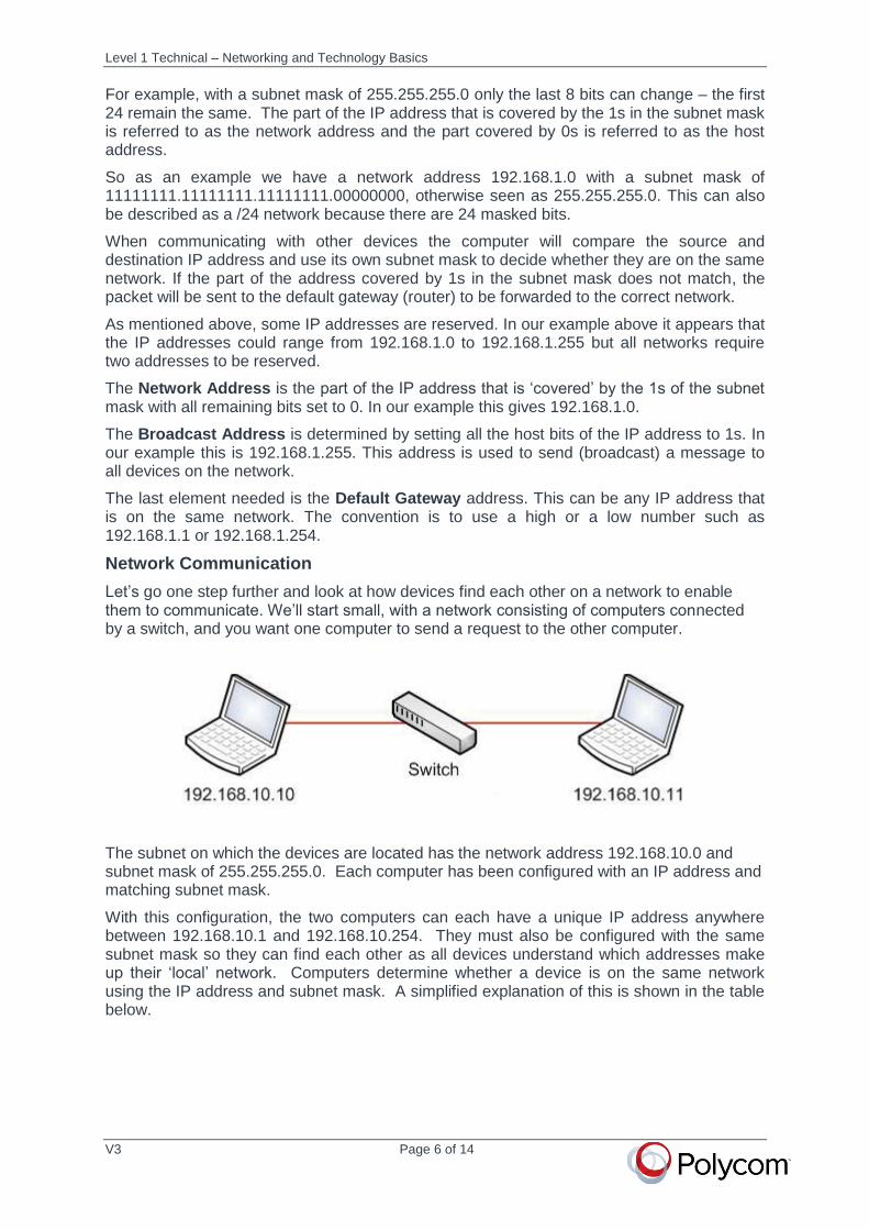
Let’s go one step further and look at how devices find each other on a network to enable them to communicate. We’ll start small, with a network consisting of computers connected by a switch, and you want one computer to send a request to the other computer.
The subnet on which the devices are located has the network address 192.168.10.0 and subnet mask of 255.255.255.0. Each computer has been configured with an IP address and matching subnet mask.
With this configuration, the two computers can each have a unique IP address anywhere between 192.168.10.1 and 192.168.10.254. They must also be configured with the same subnet mask so they can find each other as all devices understand which addresses make up their ‘local’ network. Computers determine whether a device is on the same network using the IP address and subnet mask. A simplified explanation of this is shown in the table below.
Level 1 Technical – Networking and Technology Basics
V3 Page 7 of 14
The source computer uses three pieces of information – its own IP address, the IP address of the destination computer and its own subnet mask. Using these it can work out its own network address (the part covered by the subnet mask) and compare this with the address of the destination computer. In this example both have the same network address so they can communicate directly.
IP Address Subnet Mask Network Address Host Address
Source 192.168.10.10 255.255.255.0 192.168.10 10
Destination 192.168.10.11 192.168.10 11
To understand how the computers communicate we first need to look at another type of address covered briefly in earlier courses.
MAC Addresses
In addition to IP addresses, each network device is also assigned a Media Access Control, or MAC address. This permanent, unique address is assigned in manufacturing, and is typically never changed. MAC addresses are also known as hardware addresses or physical addresses. It is the MAC address that is used for communication between devices on the same network.
Like IP addresses MAC addresses are made from binary digits but are 48 bits in length. However, unlike IP addresses they are shown as hexadecimal numbers (base 16). To achieve the 16 ‘numbers’ required hexadecimal uses numbers 0-9 followed by A-F.
The example below shows a typical MAC address -
A4-4E-31-52-EF-18
The first half of a MAC address contains the ID number of the adapter manufacturer (in this case Intel) and the second half represents the serial number assigned to the adapter by the manufacturer.
There is one VERY important distinction between MAC addresses and IP addresses. Many devices can use the same IP address provided that they are on separate private networks. A good example of this is the IP addresses on the 192.168.1.0 network which are used by vast numbers of home networks. Provided the external (public) address of the network is unique this is not a problem. However, a MAC address must always be unique and manufacturers are responsible for ensuring that there are no duplicates.
Using MAC Addresses for Communication
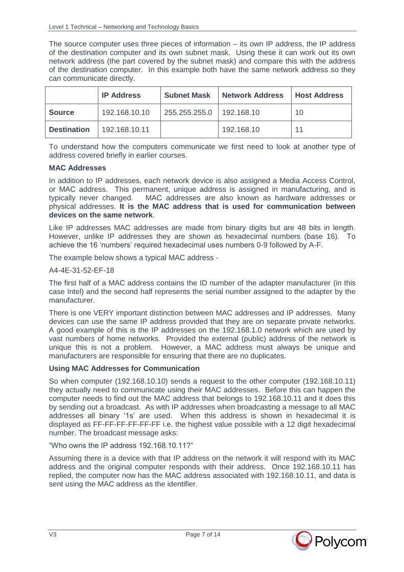
So when computer (192.168.10.10) sends a request to the other computer (192.168.10.11) they actually need to communicate using their MAC addresses. Before this can happen the computer needs to find out the MAC address that belongs to 192.168.10.11 and it does this by sending out a broadcast. As with IP addresses when broadcasting a message to all MAC addresses all binary ‘1s’ are used. When this address is shown in hexadecimal it is displayed as FF-FF-FF-FF-FF-FF i.e. the highest value possible with a 12 digit hexadecimal number. The broadcast message asks:
“Who owns the IP address 192.168.10.11?”
Assuming there is a device with that IP address on the network it will respond with its MAC address and the original computer responds with their address. Once 192.168.10.11 has replied, the computer now has the MAC address associated with 192.168.10.11, and data is sent using the MAC address as the identifier.
Level 1 Technical – Networking and Technology Basics
V3 Page 8 of 14
Communication Between Multiple Networks
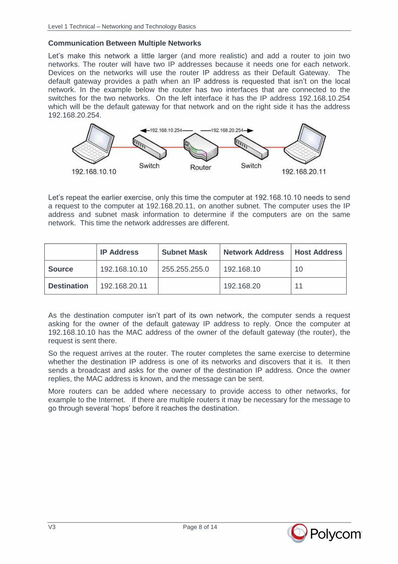
Let’s make this network a little larger (and more realistic) and add a router to join two networks. The router will have two IP addresses because it needs one for each network. Devices on the networks will use the router IP address as their Default Gateway. The default gateway provides a path when an IP address is requested that isn’t on the local network. In the example below the router has two interfaces that are connected to the switches for the two networks. On the left interface it has the IP address 192.168.10.254 which will be the default gateway for that network and on the right side it has the address 192.168.20.254.
Let’s repeat the earlier exercise, only this time the computer at 192.168.10.10 needs to send a request to the computer at 192.168.20.11, on another subnet. The computer uses the IP address and subnet mask information to determine if the computers are on the same network. This time the network addresses are different.
IP Address Subnet Mask Network Address Host Address
Source 192.168.10.10 255.255.255.0 192.168.10 10
Destination 192.168.20.11 192.168.20 11
As the destination computer isn’t part of its own network, the computer sends a request asking for the owner of the default gateway IP address to reply. Once the computer at 192.168.10.10 has the MAC address of the owner of the default gateway (the router), the request is sent there.
So the request arrives at the router. The router completes the same exercise to determine whether the destination IP address is one of its networks and discovers that it is. It then sends a broadcast and asks for the owner of the destination IP address. Once the owner replies, the MAC address is known, and the message can be sent.
More routers can be added where necessary to provide access to other networks, for example to the Internet. If there are multiple routers it may be necessary for the message to go through several ‘hops’ before it reaches the destination.
Level 1 Technical – Networking and Technology Basics
V3 Page 9 of 14
Name Resolution
Finally, a little detail about the Domain Name System (DNS). A Domain Name System server is used to match a name against the IP address used to find it. This is most obviously found on the Internet (for example, navigating to www.polycom.com rather than needing to remember that we can find the website at 23.205.116.48), but it works inside the network too. This gives the flexibility to set up your email program to look for mail.domain.com instead of the internal IP address of the mail server – providing the additional benefit that if you need to change the IP address the end user doesn’t know (or care). This extends to the point that you can name all network devices for IP address resolution this way, and it is even possible to point a domain name to multiple IP addresses, which you might do for a mail server or website, so that you can use the same DNS name to get to the same place whether inside or outside the network.
The use of names instead of IP addresses means that there is an extra step when computers want to communicate. They must first send a request to their DNS server asking it to resolve the name to its IP address. Once they have this the process described above can commence.
Transport Protocols
As you can imagine, networks transmit vast amounts of data, and, as with all technology, this is governed by protocols to ensure that one computer knows what another is trying to do. Data to be transmitted is broken into tiny packages, labeled with the IP address of the receiver, and sent to their destination.
Where it needs to be confirmed that packets are received at the correct IP address, Transmission Control Protocol (TCP) is used. TCP requests confirmation from the receiver’s IP address that the address is available to receive data. The data sent using TCP is put into packets, which are numbered as part of the TCP protocol before sending to the receiver. Once the sender has received confirmation of receipt, more packets can be transmitted, and if confirmation is not received packets can be can re-sent.
As mentioned earlier, the packages used to transmit data are a very small size. For example, downloading this document took many thousands of them. Because of this volume TCP is not the only protocol used to transfer data on the internet. When speed is key, a second transmission protocol, called Universal Datagram Protocol (UDP), is used to speed the process. In UDP, packets are sent quickly without any requirement for verification of receipt by the other end.
When transmitting real time traffic (voice and video), once TCP verifies the IP address of the receiver is available to receive packets, the system automatically converts to UDP mode. This allows more efficient real-time voice and video transmission. Though you might think that using TCP is better as the packets are guaranteed to arrive, in actual fact it would damage the quality of an audio or video call, as the requirement of TCP to deliver packets in order slows down transmission considerably. For voice and video we need packets to arrive as soon as possible rather than in any particular order.
Level 1 Technical – Networking and Technology Basics
V3 Page 10 of 14
3 – Network Utilization
Data Transfer and Bandwidth
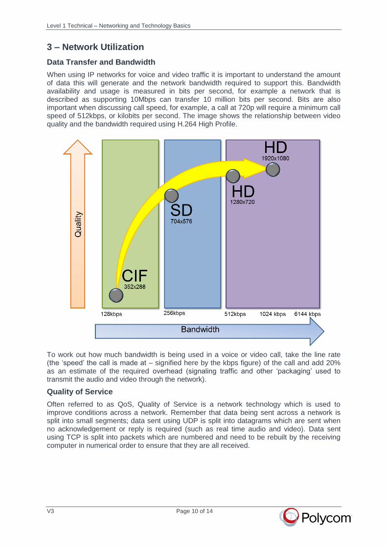
When using IP networks for voice and video traffic it is important to understand the amount of data this will generate and the network bandwidth required to support this. Bandwidth availability and usage is measured in bits per second, for example a network that is described as supporting 10Mbps can transfer 10 million bits per second. Bits are also important when discussing call speed, for example, a call at 720p will require a minimum call speed of 512kbps, or kilobits per second. The image shows the relationship between video quality and the bandwidth required using H.264 High Profile.
To work out how much bandwidth is being used in a voice or video call, take the line rate (the ‘speed’ the call is made at – signified here by the kbps figure) of the call and add 20% as an estimate of the required overhead (signaling traffic and other ‘packaging’ used to transmit the audio and video through the network).
Quality of Service
Often referred to as QoS, Quality of Service is a network technology which is used to improve conditions across a network. Remember that data being sent across a network is split into small segments; data sent using UDP is split into datagrams which are sent when no acknowledgement or reply is required (such as real time audio and video). Data sent using TCP is split into packets which are numbered and need to be rebuilt by the receiving computer in numerical order to ensure that they are all received.
Level 1 Technical – Networking and Technology Basics
V3 Page 11 of 14
Data sent across the network with no QoS is known as ‘best effort’, meaning that data sent across the network has no guarantee of bandwidth and will share the available network with other traffic such as file transfers. In some cases network congestion can result in packet loss, which is, as the name suggests, when the data gets lost. To help explain how QoS can help, let’s also consider some of other commonly used terms that will be seen when looking at call statistics:
Latency (also known as delay) is when data is delayed for some reason during
transmission; this could be due to lack of available network capacity, limited
capability of network hardware, infrastructure faults, or any number of similar issues
Queue has a similar meaning in a network as it does in real life. When data is
delayed in a switch or router due to lack of capacity, the packets and datagrams sit in
queues until reaching the front and being sent on their way
Jitter is where some packets are delayed at different rates than others, not only
through network delay or queues, but also where packets take different routes
through the network or across the internet
QoS is an extremely complex subject but put simply, QoS can help traffic in a network by marking the data with a priority coding. When the data comes to a switch or router, the higher priority data gets to take priority and skip ahead of traffic with a lower priority. These different types of traffic can be recognized in a number of ways including IP address and port number.
This conceptually enables the very high priority video and audio traffic which needs to arrive as quickly as possible to be processed before the email and internet traffic which can be delayed for a short time with less effect on service.
There are some variables which will prevent QoS being effective and need to be taken into consideration when designing an environment to run real time traffic such as video and audio. A few of these are:
Where there is just too much data to ‘fit’ on the network due to the available
bandwidth being oversubscribed; this will cause latency which can only be resolved
by reducing network traffic or increasing bandwidth
Where not all the network in use has QoS applied, for example where traffic goes
across the internet. The QoS will help while in the controlled network, but the internet
is likely to introduce latency and jitter which cannot be controlled
Where the QoS markings are incorrectly configured, for example where configuration
on devices is not consistent in the way it is instructed to handle the traffic, or where a
router might not have any QoS configuration at all, so it doesn’t understand the
markings
Level 1 Technical – Networking and Technology Basics
V3 Page 12 of 14
4 – Legacy Telephony
Following on from the brief introduction to telephony in the Introduction to Voice and Video technologies course, here’s a bit more information to help understand the different telephony models seen today.
Analog telephony
Analog telephony uses the Public Switched Telephone Network (PSTN) – also called Plain Old Telephone System (POTS) and is rarely seen in business today as the primary telephony environment. In case you’re wondering why we’re still talking about analog telephony, any business that requires a fax machine still requires an analog telephone line and so it is still a consideration in the design of a collaboration environment.
Where a fax is connected to an IP telephony system you will also find an analog telephony adapter (ATA) to enable it to ‘speak’ with both technologies at the same time and will route fax transmissions to and from the analog line.
Digital telephony
Digital telephony uses Integrated Services Digital Network (ISDN) which, on first glance, you might think to be an actual physical network but is actually a set of standards designed to allow the transmission of carry digital signals over the copper wiring used to create the PSTN. Unlike analog telephony where you can just plug an analog telephone into a socket and get dial tone, with digital telephony you need call control via a Private Automatic Branch Exchange (PABX) . Although the audio sent via ISDN is sent broken down into 0s and 1s, it is not to be confused with IP telephony which also does this but uses an IP network for transmission.
5 - IP Telephony
In its simplest form, Voice over IP is just that – voice carried over an IP network. It is (of course) a little more complex than that, however, and we’re going to delve into this a little deeper as it is relevant to Polycom Voice solutions.
System Components
There are several components in a Voice Over IP (VoIP) environment which can be implemented to get the best possible solution for a particular network. Those listed below assume that the network uses the SIP (Session Initiation Protocol) for call control. Let’s take a quick look at the most common to see what they are.
Integrated Voice Response (IVR) – automated call handling system used for call routing (commonly found in call centers to route calls to the appropriate department)
IP PABX – in the same way analog and digital telephony systems require a call control center, the IP PABX takes on this role in a VoIP environment. The PABX provides end-user services such as voicemail and automated routing and call direction for incoming calls
IP Phone – a telephone handset or device that can be registered to an IP PABX and used to make calls
IP Softphone – software downloaded to another device (mobile, laptop, tablet etc) that can be registered to an IP PABX and used to make calls in the same manner as a telephone
Proxy Server – this is used to direct a call from one part of a network to another; useful if your environment utilizes more than one registrar, for example
Registrar – also commonly known as just a SIP server, the SIP registrar is a server which accepts REGISTER requests from endpoints. Once they are registered they can be dialed using an alias rather than just an IP address. Many endpoints can register using the same alias (so that more than one phone rings when a number is dialed)
Level 1 Technical – Networking and Technology Basics
V3 Page 13 of 14
Session Border Controller – this is used to provide functions such as firewall traversal (border in this sense meaning the demarcation between two networks)
IP Telephony Protocols
Like all aspects of network technology, IP telephony is governed by a number of protocols that are designed to achieve the process of making a telephone call efficiently and effectively with the best quality audio experience possible. We’re going to split these into two categories; those which govern how the call is made, and those which determine how the audio is packaged.
Call Control
Let’s start with how to make a call. Firstly, the two devices trying to communicate must speak the same language to enable them to set up a call. Two examples of such languages will likely be familiar; Session Initiation Protocol (SIP) and H.323. We will focus on SIP here as it is more common in voice environments, simpler and easy to understand – it is based on simple plain text messages that are clear for a human and a computer, such as INVITE to start the call setup process.
Although two endpoints (voice or video) using the same protocol can communicate directly without the need for any other infrastructure, managing multiple endpoints obviously requires some additional work. In the same way that a PBX or PABX is required as a ‘brain’ for an analog or digital system, IP telephony also needs a central control solution to manage the dial plan and device configuration, and in SIP (often known just as the SIP server) this central control is called the SIP registrar. Once they are registered they can be dialed using an alias (extension number) rather than just an IP address. Many endpoints can register using the same alias (so that more than one phone rings when a number is dialed).
Voice Codecs
So, once the call is up and connected, how does the audio get to the other end? The process of converting (coding) an analog waveform into a digital signal consists of a number of different processes, including the sampling of the waveform and compression of the signal for efficient transmission.
These processes are governed by their own protocols, the names of which may be familiar such as G.711 and G.729. The coding and decoding of signals is achieved by a family of protocols with differing capabilities and are commonly known as codecs (coder/decoder). Each of these codecs determine a number of factors including sample rate, compression, and how much bandwidth is used in the call process – a good example of this is the use of wideband audio, which requires up to 64kbps as opposed to the 32kbps or lower achievable with narrowband audio.
A VoIP telephone can generally understand many different codecs. So what makes it choose one over the others? Well, in the same way that you do if you can speak more than one language – the phone negotiates with the far end. The server may have configuration which forces the priority of certain codecs over others, or the far end handset or device may have restrictions, so the phone will make the call using the codec deemed most suitable by both ends.
Dial Plans
As briefly mentioned previously, a dial plan is a numbering scheme which defines how many (and which) digits must be dialed per extension. When implementing any kind of communications solution a dial plan must be considered to take into account current and future needs, for example, if there are 1000 users, it is no good having a dial plan which allocates extensions 100-999.
Level 1 Technical – Networking and Technology Basics
V3 Page 14 of 14
This becomes more complex when integrating one communications solution into another new or existing one. For example, if a dial plan for the telephony system is fully established and there is a requirement to integrate a new videoconferencing solution, care must be taken to ensure that the dial plan is suitable for both, especially where the future needs were not taken into account. This topic will be something we revisit at each level of training.
6 – Conclusion
This guide has provided a further foundation to the fundamentals covered in the Level 1 Introduction to Voice and Video Technologies course.
It will be of assistance when working through the Level 1 Technical courses and ILT.