low Energy COnsumption NETworks
DELIVERABLE D4.3
ABSTRACTION LAYER FINAL DEFINITION
Grant Agreement Number: 258454
Project Acronym: ECONET
Project Title: low Energy COnsumption NETworks
Funding Scheme: Collaborative Project
Starting Date of the Project: 01/10/2010 dd/mm/yyyy
Duration: 36 months (original), 39 months (amendment request)
Project Coordinator:
Name: Raffaele Bolla
Phone: +39 010 353 2075
Fax: +39 010 353 2154
e-mail: [email protected]
Due Date of Delivery: M28 Mx (31/01/2013 dd/mm/yyyy)
Actual Date of Delivery: 05/02/2013 dd/mm/yyyy
Workpackage: WP4 – Green Abstraction Layer
Nature of the Deliverable: R
Dissemination level: PU
Editors: DCU, CNIT, ALU, MLX, LQDE, TEI, WUT, NVR, LGT,
INFO
Version: 1.0
Page 2 of 36
FP7-ICT-258454 D4.3
Disclaimer
The information, documentation and figures available in this deliverable are written by the
ECONET Consortium partners under EC co-financing (project FP7-ICT-258454) and do not
necessarily reflect the view of the European Commission.
The information in this document is provided “as is”, and no guarantee or warranty is given that
the information is fit for any particular purpose. The reader uses the information at his/her sole risk
and liability.
Copyright
Copyright © 2013 the ECONET Consortium. All rights reserved.
The ECONET Consortium consists of:
CONSORZIO NAZIONALE INTERUNIVERSITARIO PER LE TELECOMUNICAZIONI,
ALCATEL-LUCENT ITALIA S.p.A.,
MELLANOX TECHNOLOGIES LTD - MLNX,
LANTIQ Deutschland GmbH,
ERICSSON TELECOMUNICAZIONI,
TELECOM ITALIA S.p.A.,
GREEK RESEARCH AND TECHNOLOGY NETWORK S.A.,
NAUKOWA I AKADEMICKA SIEC KOMPUTEROWA,
DUBLIN CITY UNIVERSITY,
TEKNOLOGIAN TUTKIMUSKESKUS VTT,
POLITECHNIKA WARSZAWSKA,
NETVISOR INFORMATIKAI ES KOMMUNIKACIOS ZARTKORUEN MUKODO
RESZVENYTARSASAG,
ETHERNITY NETWORKS LTD,
LIGHTCOMM S.R.L.,
INFOCOM S.R.L.
This document may not be copied, reproduced or modified in whole or in part for any purpose
without written permission from the ECONET Consortium. In addition to such written permission
to copy, reproduce or modify this document in whole or part, an acknowledgement of the authors of
the document and all applicable portions of the copyright notice must be clearly referenced.
Page 3 of 36
FP7-ICT-258454 D4.3
Table of Contents
DISCLAIMER .................................................................................................................................... 2
COPYRIGHT ..................................................................................................................................... 2
TABLE OF CONTENTS .................................................................................................................. 3
1. EXECUTIVE SUMMARY........................................................................................................ 4
2. INTRODUCTION ...................................................................................................................... 5
3. DEFINITION OF GAL ............................................................................................................. 5
3.1. GAL MODULE ...................................................................................................................... 6
3.2. DEFINITION OF EAS AT THE DATA-PLANE ............................................................................ 9
3.3. STANDARD INTERFACES TOWARD THE CONTROL-PLANE .................................................... 10
4. IMPLEMENTATION OF THE GAL MODULE ................................................................. 11
4.1. GAL WORKFLOW ............................................................................................................... 11
4.2. GAL API ............................................................................................................................ 13
4.3. GAL NAMESPACE ............................................................................................................... 16
4.4. GAL STATE SPACE ............................................................................................................. 17
5. CONCLUSIONS ...................................................................................................................... 18
APPENDIX A: NETFPGA-BASED GAL MODULE .................................................................. 20
A.1. NETFPGA PLATFORM ........................................................................................................ 20
A.2. NETFPGA-BASED GAL MODULE ....................................................................................... 21
APPENDIX B: NETFPGA-BASED GAL IMPLEMENTATION WITH C/LINUX ................ 25
B.1. SOURCE CODE STRUCTURE ................................................................................................. 25
B.2. PARAMETERS AND DATA STRUCTURE ................................................................................. 28
APPENDIX C: THE IMPLEMENTATION OF THE GAL MODULE FOR THE DROP
ROUTER .......................................................................................................................................... 34
REFERENCES ................................................................................................................................. 35
Page 4 of 36
FP7-ICT-258454 D4.3
1. Executive Summary
The objective of the ECONET project is to investigate, develop and test new capabilities for
Future Internet devices that can enable the efficient management of power consumption and greatly
reduce the current network energy waste. To achieve this goal, the ECONET project focuses its
research and development efforts along three main research axes:
Green Technologies for Network Device Data Plane
Green Strategies at the Control Plane
Green Abstraction Layer
WP4 is devoted to the definition and implementation of the Green Abstraction Layer, which
provides a standard and general purpose interface for exposing and controlling the novel green
capabilities and functionalities towards control and monitoring frameworks.
This document is the final definition and specification of the ECONET Green Abstraction Layer
(GAL). It refines and completes the definition of the GAL structure and energy-aware capabilities
presented in deliverable D4.1, and further details the Green Standard Interface and the basic
command set defined in deliverable D4.2. Deliverable D4.1 introduced the GAL by discussing its
applicability scenario and its design goal, by proposing a first design of the GAL hierarchical
architecture, and defining what energy-aware states are and how they must be represented.
Deliverable D4.2 introduced the Green Standard Interface definition and the basic command set of
the Green Standard Interface. Building on deliverables D4.1 and D4.2, this deliverable gives the
final definition of GAL architecture, energy-aware states at data-plane and standard interfaces
towards the control-plane, and provides the detailed description of the implementation of the GAL
module.
The GAL framework is currently being discussed for standardization within the European
Telecommunications Standards Institute (ETSI) Environmental Engineering Technical Committee
under Work Item DES/EE-0030.
Page 5 of 36
FP7-ICT-258454 D4.3
2. Introduction
The Green Abstraction Layer (GAL) research axis of ECONET project is devoted to the study
and the development of the GAL and is the key to the integration and the development of the
energy-aware device prototype platforms, including both the data-plane green capabilities and
control strategies. The GAL defines a novel standard way for managing and monitoring energy and
performance profiles of device hardware.
The GAL is a standard interface between data and control planes for exchanging data regarding
the power status of a device. This standard interface is specifically conceived to hide the
implementation details of energy-saving approaches, as well as to provide standard interfaces and
methodologies for interactions between heterogeneous green capabilities and hardware (HW)
technologies, on one hand, and control and monitoring frameworks, on the other hand. Using the
GAL control, applications can access information on power management settings available at the
data-plane and on the potential effect of using such settings. In addition, control applications will be
capable of setting power-management configurations on the device data-plane.
In order to provide the information needed by control applications to reduce the energy
consumption while meeting Quality of Service (QoS) constraints, the GAL must explicitly represent
the impact on network performance when different power management settings are applied. Thus,
the GAL defines the Energy-Aware State (EAS) as an operational power profile mode of an entity
that can be configured by control plane processes. To assure the correct exchange of information,
EASes are represented by a complex data type, which contains indications on the power
consumption and the performance of an entity when working in such a configuration.
The Green Standard Interface (GSI) is a simple internal interface of the GAL for exchanging
power management information among data-plane elements and processes realizing control plane
strategies in a standard and simplified way. In order to implement the GAL architecture, ECONET
defines a set of abstract commands that work at different detail levels and that can be applied for
intercommunication between the control plane and the data plane.
This deliverable presents the final definition of the GAL, EAS and GSI, and provides a detailed
description of the implementation of the GAL module. The document is organized as follows:
Section 3 defines the hierarchical structure of the GAL as well as the definition of EAS and GSI;
Section 4 presents the implementation scheme for the GAL module. Appendix A and B show the
implementation of the GAL module for a NetFPGA Frequency Scaled Router, and define the
structure and functionalities of the GAL module.
3. Definition of GAL
To inhibit energy waste due to over-provisioned capacity, hardware devices of next generation
networks are expected to include advanced power management capabilities, which can enter
different power states according to the input traffic while ensuring the quality of service (e.g.,
entering sleep-mode during idle intervals and scaling the processing power according to the offered
workload) [1][2], and such devices and technologies are already available [1]. At the same time,
network protocols are extending with energy-aware information, and evolving towards energy-
efficiency, by adding energy-indexes into network optimisation strategies [4][5]. The efficiency of
the power management of network devices heavily depends on the specific implementation and
Page 6 of 36
FP7-ICT-258454 D4.3
low-level details of the hardware platforms of devices, which may be quite heterogeneous and can
prevent network-wide control policies (NCPs) from maintaining knowledge of underlying hardware
peculiarities related to energy consumption. To overcome these challenges, the ECONET project
has developed the GAL and the GSI, providing a standard method for accessing and managing
power states between the low-level hardware components and control processes; it has also
specified and developed the concept of EAS, defining the operational power profile modes of
network devices which can be configured by control plane processes.
3.1. GAL Module
Power management is usually realized inside hardware components of the network device, while
network control processes (e.g., routing protocols, traffic engineering frameworks, etc.) run at the
device level [6][7]. NCPs often treat a network device as a node in a graph, and may not have the
ability of discriminating how logical network entities can be mapped onto physical components
which directly cause energy absorption. When new device configurations are decided by control
processes, they have to be translated into specific settings of components at underlying levels. For
example, if a control-plane process decides to scale the speed of a path, it has to pass this command
to the chassis, and then to the line-card, and then to the related hardware components (e.g., chips,
link interfaces, etc.). Thus, a single configuration decided at the device level, depending on the
internal device architectures, may impact on multiple underlying components. Where this process
terminates depends on the device level individual manufacturers make public. In order to address
these complex aspects and internal iterations, the ECONET project modelled the GAL with a
hierarchical representation of the device, representing the components at the various levels, and
providing a standard exchange of information among the policies at various levels.
The reference module of the GAL is as shown in Figure 1. The GAL is located between data-
plane green capabilities and control-plane strategies, it provides a common and hardware-
independent interface (i.e., the GSI) to control processes, and hides the heterogeneous hardware
implementation details by means of the convergence layer interface (CLI).
Link Interface
Link Interface
ProcessorCore Chip
Fan
Green Abstraction Layer (GAL)
LCPs Smart StandbyPower scaling
NCPsRouting Tactics
Traffic Engineering
Network-wideMonitor & Management
ControlPlane
DataPlane
Green Standard Interface (GSI)for Control Plane
Convergence Layer Interface (CLI)for Data Plane
Figure 1: The role of the Green Abstraction Layer.
Page 7 of 36
FP7-ICT-258454 D4.3
Northbound, the main sets of control plane processes [9] supported are:
Local Control Policies (LCPs): that dynamically optimize the rate of energy consumption to
maintain network performance as traffic load changes. The LCPs are dependent on the
structural information of the devices they are controlling, including the internal architecture,
topology structure and energy-aware capabilities of each device element. LCPs use this
information combined with network performance indices to achieve optimization.
Network-wide Control Policies (NCPs): which provide device group optimisation
capability for network level behaviours such as traffic flow path optimisation with
guaranteed network performance for reducing overall network energy consumption.
Network Monitoring and Management frameworks: which support user-driven
configuration instead of autonomic configuration and extend current network technologies
and protocols by considering energy metrics.
Southbound, the GAL deals with data-plane physical components whose power consumption can
be controlled and monitored [9]. Such components may be:
Hardware components: such as integrated circuits (ICs), General Processing Units (GPUs),
connectors or controllers, link interfaces, etc. These hardware components provide power
scaling and standby primitives, which allow energy management operations including
energy consumption monitoring.
Auxiliary systems: such as power supply, cooling systems including fans, etc. Energy
management operations can tune these auxiliary systems’ performance to match the energy
configuration of the host device.
Control strategies may act at various levels (e.g., single component, line-card, chassis and device
levels), and this depends on the internal topology/architecture of the device and manufacturers'
preference. For example, fans in a chassis and in a line card have different accessibilities for the
control-plane, and some manufacturers shall prefer not to expose the internal architecture and the
subcomponents of a composite part of the device (e.g., line-card, chassis, etc.). Therefore, control-
plane processes must be capable of setting components (at various resolution levels) into a certain
energy configuration in terms of power consumption and performance through the GAL. Starting
from these considerations, the ECONET project defined the GAL following the hierarchical
structure represented in Figure 2.
The GAL provides a hierarchical representation of device data-plane architectures, and represents
a device or the sub-components of it at various levels as Entities, which can be accessed by control-
plane processes through the GSI. Higher-level entities may attach one or more entities at lower
levels. The hierarchy depth must depend on the specific internal architecture of the network device.
At the highest level (i.e., device level), the entire device corresponds to an entity (Entity 1). At
medium hierarchical levels, it may correspond to line-cards, chassis, etc. For example, Entity 1.2 in
chassis level, Entity 1.2.2 in line-card level. At the lowest hierarchical level (i.e., hardware
component level), an entity (e.g., Entity 1.2.2.2) may correspond to a chip, a processor, a link
interface. The specific hierarchical structure of the GAL depends on the internal
topology/architecture of the device and manufacturers' preference. The communication between the
GAL and physical components is realized through the CLI, which includes all the drivers for setting
or acquiring parameters from the supported energy-aware physical elements through the access to
registers and tables dependent on the specific hardware development.
Page 8 of 36
FP7-ICT-258454 D4.3
GSI
Entity 1
LCPDevice Level
GSI
Entity 1.1
CLI
GSI
Entity 1.2
LCP
Chassis Level
GSI
Entity 1.2.1
CLI
GSI
Entity 1.2.2
LCP
GSI
Entity 1.2.3
CLI
GSI
Entity 1.2.2.1
CLI
GSI
Entity 1.2.2.2
CLI
GSI
Entity 1.2.2.3
CLI
GSI
Entity 1.2.2.4
CLI
GSI
Entity 1.2.2.5
CLI
Line-card Level
Hardware component Level
Direct access to
the hardware
component if
manufacturers
prefer not to
expose the
internal
architecture of
chassis/linecard
Direct access to
the hardware
component If
the physical
resource is
available at
intermediate
layers (e.g.,
fans in chassis)
Logical Entity 1.1.0.0
Logical Layer
Physical Layer
Logical Entity 1.2.1.0
Logical Entity 1.2.2.6
Logical Entity 1.2.3.0
...
Chip in
Card II
Optical Port inCard II
EthernetPort inCard II
Fan inCard II
Fan inChassis
II
Card I in
Chassis II
Card II inChassis II
Chassis I in
Device I
Data
Plane
ControlPlane
SNMPOSPFNetwork Control
ProcessesOAM
Chassis II in
Device I
Device I
CPU in
Card II
Figure 2: The hierarchical structure of the Green Abstraction Layer.
The GAL framework is a multi-layer hierarchical interface that allows the intercommunication
among multiple local and network-wide control planes and the data-plane hardware. The different
layers present various abstraction levels of a power-managed device. At the top of the hierarchy the
GAL connects NCP processes, which work on the logical resources of the device and often lose the
details on how they can be mapped onto internal hardware components, where power consumption
and management physically happen. Thus, NCPs may drive power configurations of network
devices only by means of such logical resources. The GAL consequently exposes a number of
“hooks” towards NCPs by adding a further GAL layer just above the device level, one for each
logical resource, and abstract/aggregate there the power settings available at the physical layer.
Therefore, the GAL has the following features:
Provides a hierarchical view of the different hardware components of network devices, and
hides the hardware components’ architecture and complexity from the management system;
Provides a structured methodology for the control-plane to acquire and manage the energy-
aware capabilities of GAL-compliant devices;
Page 9 of 36
FP7-ICT-258454 D4.3
Enables LCPs to translate high-level commands (passed through the GSI) from the control-
plane into low-level commands towards the data-plane;
Enables the highest-level LCP to expose all the logical resources of network devices, whose
number and types are dynamic and depend on the device configuration, to the NCPs;
Facilitates NCP-LCP and inter-device LCP-LCP communication, and enables NCPs to see
the effect of the application of a LCP and to set parameters or constraints that determine the
operating behaviour of the LCP.
3.2. Definition of EAS at the Data-Plane
Using the GAL, control applications can get information on energy-aware settings available at the
data-plane, and are capable of setting a certain energy-aware configuration on the device data-plane.
Different hardware components provide heterogeneous energy-aware capabilities, and the
formalization of energy-aware control parameters is done through the definition of EAS.
An Entity is defined [9] as a device or sub-component of a device which the GAL can access and
configure through a standard interface. An Entity can exist at a number of levels, i.e.: an integrated
circuit, a network processor or a link interface at a component level; line-cards, chassis, etc. are
examples of intermediate level entities; or the entire device itself at the highest level. Higher-level
entities can include one or more entities at lower (and multiple) levels. The depth and the hierarchy
of the entire device entity are dependent on the internal topology/architecture of each specific
network device.
An Energy-Aware State (EAS) is defined [9] as an entity power setting that can be configured
through the GAL, and that may impact on the power consumption, the performance, the available
functionalities, and the responsiveness of the same entity. An EAS can be considered as an
operational power profile mode implemented by the entity that can be configured by control plane
processes. To assure the correct exchange of information between the entity and control plane
processes, the EAS is represented as a complex data type, containing indications on the power
consumption, the performance, the available functionalities, and the responsiveness of the entity
when working in such configuration.
The energy-aware capabilities implemented by ECONET are dynamic power scaling and smart
standby. Power scaling is the capability of adjusting the energy requirement of an entity by
dynamically scaling its processing frequency or the transmission and reception speed, while smart
standby is the capability of an entity to switch itself or a part of itself into a very low energy mode,
providing only some vital functionalities (e.g., wake-up triggers). The energy-aware capabilities
have different operational behaviours depending on the specific implementation, (i.e., the device
intelligence), and the hierarchical level of an entity. Some aspects may be managed by control
processes external to the entity, some others by the entity itself in an autonomic way depending on
its workload. Only those Entities controllable by the control-plane processes can be represented as
different EASes.
Control processes select the EAS that provides the desired operational behaviour to meet QoS
constraints. EASes are associated with attributes (e.g., maximum throughput, power consumption,
wake-up time), for characterising the performance and power consumption under each EAS setting.
Assuming there are totally N available EASes, each EAS can be modelled as a list of attributes:
𝑆𝐸𝐴𝑆(𝑛)
= {𝑃𝑤(𝑛), 𝑃𝑟
(𝑛), 𝑇𝑑
(𝑛)} 𝑛 ∈ {0,1, … ,𝑁 − 1}
Page 10 of 36
FP7-ICT-258454 D4.3
where:
𝑆𝐸𝐴𝑆(𝑛)
represents the 𝑛𝑡ℎ EAS,
𝑆𝐸𝐴𝑆(0)
is the sleeping state where the entity is turned off and the maximal power saving can
be obtained,
𝑆𝐸𝐴𝑆(1)
is a low-power state with the lowest performance level while still being active
(consumes the least power in active state),
𝑆𝐸𝐴𝑆(𝑁−1)
is the highest-power state with the highest network performance (it also consumes
the highest power),
𝑃𝑤(𝑛)
are the power consumption related values (e.g., power consumption, power saving
gain compared with the highest-power state), which are useful to estimate the global
energy absorption of the equipment when working with the selected EAS,
𝑃𝑟(𝑛)
are network performance related indexes (e.g., throughput, packet drop rate), which
are needed to verify if the current energy state meets the QoS requirements to serve the
expected offered-load,
𝑇𝑑(𝑛)
are state transition features (e.g., wake-up time), which allow the control processes to
evaluate the set of states (EASes) reachable from the selected one, giving information
regarding transition delays or possible service interruption periods of the device.
3.3. Standard Interfaces toward the Control-Plane
The GAL framework includes two main interfaces, namely, the GSI and the CLI. The former
represents the standard part of the GAL and the latter maps GAL commands and data into low-level
configuration registers/APIs, which are often manufacturer/HW specific. The GSI provides the
command set necessary to setup the power management and monitoring of a wide set of energy-
aware resources and network devices. In other words, the GSI is used to access resources and their
power characteristics discovery, the autonomic provisioning and manual configuration of resources,
the monitoring and the decommissioning of energy-aware physical resources.
In order to communicate with NCPs through logical resources, a logical layer is included on top
of the highest-level LCP of the HW tree (the one working at the device level), as represented in
Figure 2. The logical resources are mappings of certain physical entity/entities and locate on top of
the GAL root. The type and the nature of logical resources depend on the specific network device.
The number of leafs of GAL nodes depends on the specific network device architecture and on
manufacturer integration choices. The visibility of internal structural and architectural details
including control mechanisms varies from manufacturer to manufacturer. Devices may have full or
partial autonomic capabilities and because of this each GAL node is designed [8] to accommodate a
number of children at different levels. However if no children are present, then a direct binding to
the data-plane must be present.
The GSI manages all accesses to GAL resources. Access permissions including “read/write” are
hierarchical. In other words, information and control at lower levels is only available to high(er)
level LCPs. All instances of GSIs in the hierarchy structure provide the same methods and data
types. EAS data structures represent all available and configurable energy-aware settings of entities.
Each GSI method is singular (i.e., one configuration change requests one command), and multiple
commands are not allowed. The GSI supports “commit/rollback” methods, which provides
Page 11 of 36
FP7-ICT-258454 D4.3
flexibility to investigate configuration options (e.g., a chain of different EAS requests), before
committing changes to the device HW. The performance indexes and available EASes for each
entity will be updated if an EAS configuration command is sent through the GAL.
The GSI is the northbound interface of a generic GAL instantiation. Although the exact
implementation will depend on the devices deployed in a specific instance (e.g., network elements,
network cards, chips, fans, and so on), ECONET specifies a set of messages and workflows
defining the abstract messages to enable the GAL interface to operate. The main functionalities
offered by the GSI are the following:
Discovery: used to retrieve information about: available power states and other descriptive
information of the entity; monitoring points for reading power-related information; the list
of individually manageable components within the entity and their relation (both logical and
physical).
Provisioning: It allows the configuration of an entity into a certain power state.
Release: It allows the release of already configured physical devices, in the sense that the
device assumes its default configuration.
Monitoring: It permits to monitor relevant parameters (state, power consumption, etc.) of
the physical device.
Commit: It confirms the changes done in the provisioning request.
Rollback: It is the inverse of the Commit command. It undoes the changes done in the
provisioning request, or rolls back to the last committed configuration.
4. Implementation of the GAL Module
This section describes the actions of implementing the GAL. Note, however, that it is not
intended to constrain the internal architecture of any conformant implementation. To give hardware
vendors flexibility in choosing their implementation, we use tables to describe system information,
features, and methods for controlling those features.
4.1. GAL Workflow
To generalize the GAL workflow of managing and monitoring the power configuration of
hardware elements in a network device, let us consider a simple example of EAS configuration
through the GAL, and the procedures can be divided into five phases. In the first phase, the NCP
(e.g., routing protocol extended to consider energy-aware metrics) acquires the current EAS and the
available EASes (with their associated attributes) from all network nodes. In the second phase, upon
the acquisition of all the available EASes and their associated attributes and on the basis of
available traffic and network performance constraints, a centralized or distributed algorithm
computes a new network configuration, which will include updates of the routing/switching tables
and of configuration parameters in each node. In the third phase, the local instance of the routing
protocol updates routing/switching table entries and interacts with the device-level LCP to assure
that the LCP works under the required configuration parameters, such as the set of EAS candidates,
the decision-making interval, and the wake-up time when working in smart standby mode. In the
fourth phase, the device-level LCP searches which sub-entities are involved, and forwards the
incoming request towards lower-level entities; this phase iterates by medium-level LCPs, until it
Page 12 of 36
FP7-ICT-258454 D4.3
reaches the bottom-level LCP, which can directly access data-plane hardware components by means
of the CLI. In the fifth phase, the bottom-level LCPs dynamically configure the EASes of each
component.
From this procedure, we can see that control-plane processes finally reach the device level entity
in order to acquire EAS information, and provision or monitor the state of each of the logical
entities in the device. Therefore, each device-level entity should provide a User Interface for
implementing the command set mentioned above. The main workflow of managing and monitoring
the power configuration can be generalized as in Figure 3.
Agent
GAL Library
Local Control Policy (LCP)
Tables of Hardware Driver
Control-Plane
Hardware
Data Plane Hardware Register
User Interface
Device Module
Logical Resource
Logical entity ?NoYes
Hardware Module
Figure 3: Workflow of GAL Implementation.
The control-plane processes generate an appropriate control message, which consists of a
version identifier (e.g., version-1.0), an application name (e.g., OSPF-TE/RSVP-TE
[4][5]), and a protocol data unit (PDU), which contains the command and its parameters
for power management.
The device-level entity has an Agent to receive control-messages. The agent performs a
rudimentary parse of the incoming control-messages, and verifies the version number,
application name, and source and destination addresses. If the parse is successful, it passes
the PDU to the User Interface which implements the desired functionality. If the parse
fails, it discards the datagram and performs no further actions.
The User Interface calls the corresponding functionality from the GAL Library.
The corresponding functionality in the GAL Library forwards the request to the specific
device Module.
Page 13 of 36
FP7-ICT-258454 D4.3
If the command can reach the logical entity, the device module calls the corresponding
functionality in the logical resources, and the logical resource functionality passes the
request to the Local Control Policy (LCP). Otherwise, the device module directly calls the
LCP.
The corresponding functionality of the LCP interprets the high level states and sets the
corresponding low level states in the hardware module.
The hardware module finally reaches the hardware component by accessing the
corresponding hardware registers or corresponding tables of the hardware driver.
The basic structure of the control-message is as shown in Table 1. It is mandatory that all
implementations of the GAL support the six PDUs: Discovery-PDU, Provisioning-PDU, Release-
PDU, Monitoring-PDU, Rollback-PDU and Commit -PDU.
Table 1: The basic structure of the control message.
Field Value Description
Version INTEGER Indicates the version of this GAL protocol
Application OCTET STRING Indicates the application name which sends the message
PDU ANY Indicates the command and its parameters for power
management.
4.2. GAL API
The Green Standard Interface (GSI) is the northbound interface of a generic GAL instantiation.
Although the exact implementation will depend on the devices (e.g., network elements, network
cards, chips, fans, and so on…), we propose a set of abstract messages here (i.e., APIs) to enable the
GAL interface to operate. The API offered by the GSI is listed in Table 2.
Table 2: GSI API.
Functionality Direction Description
DISCOVERY
Information request
GAL client → Entity
It is used to retrieve information about: the current
power state set in the entity; available power states and
other descriptive information of the entity; monitoring
points for reading power-related information.
Information response
GAL client ← Entity
It returns the list of individually manageable
components within the entity and their relations (both
logical and physical).
PROVISIONING
Configuration command
GAL client → Entity
It allows the configuration of an entity into a certain
power state.
Configuration notification
GAL client ← Entity It returns the operating results.
Page 14 of 36
FP7-ICT-258454 D4.3
Functionality Direction Description
RELEASE
Decommissioning command
GAL client → Entity
It allows the release of already configured physical
devices, in the sense that the device assumes its default
configuration.
Decommissioning notification
GAL client ← Entity It returns the operating results.
MONITORING
Parameters request
GAL client → Entity
It permits to monitor relevant parameters (state, power
consumption, etc.) of the physical device.
Parameters notification
GAL client ← Entity It returns the operating results.
COMMIT
Confirmation command
GAL client → Entity
It permits to confirm the changes done in the
provisioning request.
Confirmation notification
GAL client ← Entity It returns the operating results.
ROLLBACK
Rollback command
GAL client → Entity
It is the inverse of the Commit command. It undoes the
changes done in the provisioning request, or rolls back
to the last committed configuration.
Rollback notification
GAL client ← Entity It returns the operating results.
The next paragraphs introduce each API and its parameters. The DISCOVERY command permits
the retrieval of a set of available pieces of information about the selected device. The DISCOVERY
command parameters are shown in Table 3.
Table 3: The parameters of DISCOVERY.
Parameter Value Direction Description
resource_id char IN The ID of the resource that should perform the action
committed bool IN
If TRUE (or 1), returns the information of the last
committed state;
If FALSE (or 0), returns the information of the current
state (set with the last provisioning command).
logical_resources list OUT The list of logical resources of the device
physical_resources list OUT The list of physical resources of the device
sensor_resources list OUT The list of sensors resources of the device.
power_states list OUT The list of power states available for the device
edl list OUT The list of the optimal configurations for the device
The PROVISIONING command permits configuration of the power state of the selected entity,
and its parameters are shown in Table 4.
Page 15 of 36
FP7-ICT-258454 D4.3
Table 4: The parameters of PROVISIONING.
Parameter Value Direction Description
resource_id char IN The ID of the resource that should perform the action
power_state int IN The power state that has to be set for the entity
The MONITORING set of commands permits monitoring the current power state of a resource,
the history of the power states previously occupied on a resource and the current readings of a
sensor. The parameters of each function are shown in the following Tables.
Table 5: The parameters of MONITOR STATE.
Parameter Value Direction Description
resource_id char IN The ID of the resource that should perform the action.
power_state int OUT The current power state of the entity.
Table 6: The parameters of MONITOR SENSOR.
Parameter Value Direction Description
resource_id char IN The ID of the resource that should perform the action.
oper_status char OUT The operational status of the sensor.
sensor_value list OUT
The list of current values of the sensor reading.
Valid values are:
voltsAC: electric potential
voltsDC: electric potential
amperes: electric current
watts: power
hertz: frequency
celsius: temperature
other: a measure other than those listed above
unknown: unknown measurement
value_timestamp TIME OUT The timestamp of the reading.
Table 7: The parameters of MONITOR HISTORY.
Parameter Value Direction Description
resource_id char IN The ID of the resource that should perform the action.
power_state_history list OUT The list of power states committed on the resource, in
descending order of the time committed.
Page 16 of 36
FP7-ICT-258454 D4.3
The RELEASE command puts the device or entity into its default configuration. The COMMIT
command permits confirmation of the changes made in the provisioning request, and its parameters.
Finally, the ROLLBACK command allows a return back to the last committed state, and its
parameters. The parameter for each function belonging to this set of commands is shown in Table 8.
Table 8: The parameter of RELEASE, COMMIT, and ROLLBACK.
Parameter Value Direction Description
resource_id char IN The ID of the resource that should perform the action
Every function returns the operating results in a status code, which can indicate success, various
errors, and possibly a timeout from the GAL modules. This is necessary because it is possible for
certain GSI commands to take up a few seconds to carry out, and since the operation from NCPs is
synchronous by nature, it is essential to make sure the GSI function returns in a timely fashion, so
as not to block the NCPs decisions. We define the status code as follows:
Table 9: Status code for GSI functionalities.
Status
Code Name Description
-1 GAL_TIMEOUT Indicates the operation timed out
0 GAL_SUCCESS Indicates the command has been successfully completed
1 GAL_ERROR Indicates a general error
2 GAL_NOT_IMPLEMENTED Indicates the power management function is not
implemented on the selected resouce_id
4 GAL_RESOURCE_NOT_FOUND Indicates the resource_id provided on the request is
non-existent
8 GAL_RESOURCE_NOT_AVAILABLE Indicates the resource_id provided on the request is not
available at the moment
4.3. GAL Namespace
For all Definition Blocks, the system maintains a single hierarchical namespace that it uses to
refer to objects. All Definition Blocks load into the same namespace. Although this allows one
Definition Block to reference objects and data from another (thus enabling interaction), it also
means that implementations must take care to avoid any naming collisions. Only an unload
operation of a Definition Block can remove names from the namespace, so a name collision in an
attempt to load a Definition Block is considered fatal. The contents of the namespace changes only
on a load or unload operation.
The namespace is hierarchical in nature, with each name allowing a collection of names "below"
it. All names begin with "GAL", and the object in each hierarchy is preceded with an underscore
"_". Figure 4 below shows a sample of the GAL namespace.
Page 17 of 36
FP7-ICT-258454 D4.3
GAL Lib
GAL_Object1
GAL_Object2
Device1
Logical_resource
GAL_Module_Device1_Logical_resource_Object2
LCP
GAL_Module_Device1_Object1
GAL_Module_Device1_Object2
GAL_Module_Device1_Logical_resource_Object1
GAL_Module_Device1_LCP_Object2
Component
GAL_Module_Device1_LCP_Object1
GAL_Module_Device1_LCP_Component_Object2
GAL_Module_Device1_LCP_Component_Object1
Figure 4: Namespace of GAL Implementation.
4.4. GAL State Space
In order to realize the functions of these commands, each logical entity should use two variables
to restore state information: provisioned_state and committed_state. The state of a logical entity is
the combination of these two variables, and will change after different GAL commands.
Figure 5 contains the entity state transition diagram which describes the different possible states
and the transitions between states (which are the consequence of the use of such commands). The
provisioned_state and committed_state of each logical entity can be set to the DEFAULT_STATE
after the initialization operation in implementation. The provisioned_state will be set with the
provisioned_state, and the committed_state will remain unchanged if the entity receives the
PROVISIONING command. The COMMIT command will set the committed_state with the last
provisioned provisioned_state, while the provisioned_state remains unchanged. The ROLLBACK
command will set the provisioned_state with the last committed committed_state, while the
committed_state remains unchanged. The RELEASE command will set the provisioned_state with
DEFAULT_STATE, which has the same effect as the PROVISIONING command with the
parameter of DEFAULT_STATE. The DISCOVERY command can return either information
regarding the current committed_state or regarding the provisioned_state, which depends on the
parameter sent with this command. The MONITORING command always returns information
regarding the current committed_state of the entity.
Page 18 of 36
FP7-ICT-258454 D4.3
Provisioned_state = DEFAULT_STATECommitted_state remains unchanged
Provisioned_state = Provisioned_stateCommitted_state remains unchanged
PROVISIONING
Provisioned_state remains unchangedCommitted_state = Provisioned_state
COMMIT
Provisioned_state = Committed_stateCommitted_state remains unchanged
ROLLBACK
RELEASE
RELEASE
PROVISIONING
RELEASE
RELEASE
PROVISIONING
COMMIT
COMMIT
ROLLBACK
PROVISIONING
ROLLBACK
Figure 5: Logical Entity State Transition Diagram.
5. Conclusions
This report represents the final definition of the Green Abstraction Layer (GAL) and the detailed
description of the implementation of the GAL module.
In more detail, the GAL has been defined to be a standard interface between the data and control
planes for exchanging information regarding the power status of a device. By means of the GAL, on
one hand, control applications will be allowed to get information on how many power management
settings are available at the data-plane, and on the potential effect of using such settings. On the
other hand, control applications will be capable of setting a certain power-management
configuration at the device data-plane.
In order to provide the information needed by control applications to reduce the energy
consumption while meeting the QoS constraints, the GAL defines the Energy-Aware State (EAS) as
an operational power profile mode of an entity that can be configured by control plane processes.
To assure the correct exchange of information, EASes are represented by a complex data type,
which contains indications on the power consumption and the performance of an entity when
working in such a configuration.
To be GAL compliant, the network device needs to support and implement six types of control
messages: discovery, provisioning, release, monitoring, rollback, and commit.
Page 19 of 36
FP7-ICT-258454 D4.3
The Green Standard Interface (GSI) is a simple internal interface of the GAL for exchanging
power management information among data-plane elements and processes realizing control plane
strategies in a standard and simplified way. In order to implement the GAL architecture, ECONET
defines a set of commands that work at different detailed levels and that can be applied for
intercommunication between the control plane and the data plane.
Related publications for the GAL can be found in [10] - [13], and the GAL code documentation
can be found in ECONET deliverable D4.4 [19]. Seven prototype implementations of the GAL have
been realised, tested, evaluated and successfully demonstrated during the ECONET project; two of
these prototypes are described in Appendices A-C (below). The seven prototypes range from home
gateways to high-end switches and routers, further details on these can be found in D6.4 [20].
The implementation of the GAL module for the NetFPGA Frequency Scaled Router [15][16]
(based on the NetFPGA platform [14])- is introduced in Appendixes A and B. The source code
structure and functionalities of the GAL module implemented for the NetFPGA-based Frequency
Scaled Router are shown.
The implementation of the GAL module for the Drop Router [10] is summarised in Appendix C.
The DROP router is an open source software router with a modular architecture based on Linux and
commercial off-the-shelf hardware.
The GAL framework is currently being discussed for standardization within the European
Telecommunications Standards Institute (ETSI) Environmental Engineering Technical Committee
under Work Item DES/EE-0030.
Page 20 of 36
FP7-ICT-258454 D4.3
Appendix A: NetFPGA-based GAL module
This appendix introduces the implementation of the GAL module on the NetFPGA platform,
which is an open source hardware and software platform that developers can easily and quickly
implement to test new protocols and techniques.
A.1. NetFPGA Platform
The NetFPGA platform is an accelerated network hardware platform that augments the functions
of a standard computer. It is becoming increasingly popular in various research areas, as it is a
hardware customizable router that can be used to study, implement and test new protocols and
techniques directly in hardware, providing the researchers with the possibility to experience a more
realistic experiment environment. For the NetFPGA 1G reference router, two SRAMs and the core
logic FPGA (Xilinx Virtex II pro) work synchronously. The board comes with an inbuilt register,
which enables the researchers to manually switch the operational frequency between 125 MHz and
62.5 MHz. However, a limitation with the current NetFPGA reference board is that the frequency
switch causes the board to reset and all packets being processed, in input or output queues or
SRAM, are lost.
DCU and LGT implemented a new Dynamic Frequency Scaled Router, which provides dynamic
frequency scaling capabilities between 5 different core clock frequencies: two different frequency
sets were designed and evaluated (125MHz, 83.3MHz, 62.5MHz, 50MHz, and 41.7MHz) and
(125MHz, 62.5MHz, 31.3MHz, 15.6MHz, and 7.8MHz). This provides more finely tuned
frequency switching capability into the NetFPGA router. The implementation also addressed and
eliminated the board reset problem securing the data being processed during switching.
MAC Rx1
CPU Rx1
MAC Rx2
CPU Rx2
MAC Rx0
CPU Rx0
MAC Rx3
CPU Rx3
Input
Arbiter
Output
Port
Lookup
MAC Tx1
CPU Tx1
MAC Tx2
CPU Tx2
MAC Tx0
CPU Tx0
MAC Tx3
CPU Tx3
Output
Queues
SRAM
Core Logic
With frequency scaling
capabilities
Buffers
Buffers Buffers
Figure 6: NetFPGA Frequency Scaled Router packet path.
The router pipeline is shown in Figure 6. The incoming packets from the networks (via the PHY
and MAC chips) and the host CPU are first received by the MAC Rx and CPU Rx in the Receive
Queues, respectively. The packets are then collected by the Input Arbiter via a round-robin
algorithm and pushed into the Output Port Lookup module. At this stage, the packets are processed
by a number of router operations, including MAC address verification, TTL update, IP lookup and
ARP lookup etc. After that, the packets are buffered in the SRAM to be read by the Output Queues.
Finally, the Transmit Queues read the packets from the Output Queues and send them out through
the MAC Tx (CPU Tx).
The Virtex-II Pro FPGA is the core logic, which is programmed in Verilog-HDL hardware
programming language, and realizes the functionality of the router hardware, including the storing
Page 21 of 36
FP7-ICT-258454 D4.3
and forwarding of the arriving network packets. In order to avoid a board reset with packet losses
we have changed the hardware so that the SRAM remains at full frequency operation (125 MHz),
and instead we designed the board to only change the operational frequency of the core logic
Virtex-II Pro FPGA. In order to interface the board components, which now operate at two different
frequencies, we introduced asynchronous buffers to buffer packets between the different clock
zones. A custom register allows the software running on the NetFPGA host desktop PC to
communicate with the NetFPGA hardware, and scale the core logic frequency between the five
different frequencies:set1 (125MHz, 83.3MHz, 62.5MHz, 50MHz, 41.7MHz) or set2 (125MHz,
62.5MHz, 31.3MHz, 15.6MHz, 7.8MHz). The DCM (Digital Clock Manager) in the VIRTEX-II
PRO FPGA can generate 16 different frequencies; however, the resources available on the FPGA
can only implement 5 frequencies at the same time. In the GAL module that follows frequency set1
was used.
A.2. NetFPGA-based GAL Module
The Green Standard Interface (GSI) is the northbound interface of the generic Green Abstraction
Layer instantiation and it is expected to be used by three main sets of control plane processes
including Local Control Policies (LCP), network-wide control policies (NCPs), and Monitoring and
Operation Administration & Management (OAM). The GAL has been defined in order to provide
(i) a common and simple way for representing power management capabilities available in
heterogeneous data plane hardware,
(ii) a framework for information exchange between power managed data plane entities and
control processes, and
(iii) a reference control chain allowing a consistent hierarchical organization or multiple local
and network-wide energy management protocols.
The Green Standard Interface (GSI) is in charge of providing the command set necessary to setup
the power management and monitoring of a wide set of NetFPGA router energy-aware resources
and devices. In other words, the GSI is used for accessing the NetFPGA router resources and their
power characteristics’ discovery, the autonomic provisioning and manual configuration of
NetFPGA router resources, the monitoring and the decommissioning of NetFPGA router energy-
aware physical resources. The set of messages, their functionalities and workflow of the command
set exposed by the GSI [8] to control processes are in line with the NetFPGA router architecture.
Page 22 of 36
FP7-ICT-258454 D4.3
Figure 7: The GAL Module for the NetFPGA Frequency Scaled Router.
NetFPGA Router resources manageable through the Green Standard Interface include device
level, Line-card level and Hardware component level [8]. Figure 7 shows the GAL hierarchy for the
NetFPGA Router. Each entity (local and physical) has a set of power states and a current power
state, each characterized by given QoS and power consumption.
There are 7 states for each entity: the states from 0 to 4 represent the 5 different operational
frequencies and their corresponding different levels of QoS (traffic handling capability) and power
consumption; state 0 provides the maximum QoS and has the maximum power consumption (i.e., it
represents the highest frequency of operation, 125MHz), state 4 provides the minimum QoS and has
the minimum power consumption (i.e., it represents the lowest operational frequency, 41.7MHz in
the case of set1 frequencies); state 5 represents the autonomic behaviour state, in which the entity
0.0.0 changes its own power state depending on the local traffic load; and the state 6 is a standby
state, in which the entity is in a sleeping mode. Each power state has the following QoS and power
attributes:
maximum_packet_throughput, which is the maximum packet throughput that can be
provided by the entity when working in the current state, this value is expressed in packets
per second.
maximum_bit_throughput, which is the maximum bit throughput that can be provided by
the entity when working in the current state. This value is expressed in bits per second.
minimum_power_gain, which is the minimum power gain compared with the maximum
power consumption of the entity (state 0) when working in the current state.
power_gain, which is the average power gain compared with the maximum power
consumption of the entity (state 0) when working in the current state.
Core FPGA
Page 23 of 36
FP7-ICT-258454 D4.3
wakeup_time, which is the maximum time required to move from the current state (if the
current state is standby state) to an active state.
sleeping_time, which is the maximum time required to move from the current state (if the
current state is an active state) to the standby state.
lpi_transition_power, which is the average power needed to move from the current state to
other states.
ps_transition_times, which is the maximum time needed to move from the current state to
other states.
ps_transition_service_interruption_times, which is the maximum service interruption time
that may be incurred while moving from the current state to other states.
autonomic_ps_steps, which is the power state steps that can be selected when working in
autonomic power scaling state (state 5), there are five power state steps in this NetFPGA
Scaled Router module (125MHz, 83.3MHz, 62.5MHz, 50MHz, 41.7MHz).
autonomic_ps_curves, which represents the strategy of when and how to change power state
if the current state is set to autonomic power scaling state (state 5).
autonomic_ps_service_interruption, which is the maximum service interruption time that
may be incurred when switching power states by the autonomic behaviour (state 5).
The specific features of this GAL module include the following points:
The physical layer is exposed by the GAL with read-only access: a GAL client may be aware
of which entities can be found at the lowest layer but it cannot directly communicate with
them.
The physical energy-aware elements are: the Xilinx Virtex II Pro FPGA (resource_id: 0.0.0)
with 5 grades of operational frequencies (125MHz, 83.3MHz, 62.5MHz, 50MHz, and
41.7MHz represented by 5 power state steps); and the four 1Gbps Ethernet ports
(resource_ids from 0.0.1 to 0.0.4).
The logical layer is exposed with read-and-write access: a GAL client is aware of which
logical entities are at the higher layer, and it can send them some commands, in order to
change the power states. (resource_ids from 0.0.5 to 0.0.8).
Each of the 4 logical entities depends on one real Ethernet port on the board and on the
Xilinx Virtex II Pro FPGA Chip.
Since the commands can be sent only to the logical resources, the Local Control Policy (LCP)
will interpret these high level states and set the corresponding low level states in the
hardware modules.
The following command set is implemented on the NetFPGA Scaled Router to access and
configure NetFPGA Router resources and their power characteristics:
DISCOVERY: The Discovery command shows only the properties of the logical resources:
the ID of the resource, the description (which contains the correspondent IP address) and the
Optimal Configuration list.
PROVISIONING: The Provisioning command sets the state of an entity to the specified
state. The logical resources have 7 states: the states from 0 to 4 represent different levels of
Page 24 of 36
FP7-ICT-258454 D4.3
operational frequency and resultant different levels of QoS and power consumption, state 5
represents the autonomic behaviour state and state 6 is the standby state.
MONITOR STATE: The Monitor State command returns the current power state of the
physical and logical entities.
MONITOR CONSUMPTION: The Monitor Consumption command returns the current
power consumption of the physical and logical entities.
RELEASE: The Release command sets the state of the resource to the default state. For the
NetFPGA Scaled Router logical resources the default state is the state 0: the highest
operational frequency with the maximum QoS and the maximum power consumption.
COMMIT and ROLLBACK: The GAL, (in particular the LCP), maintains a sort of
session: information related to the provisioned commands is maintained in memory and is
set to the hardware only when the commit command is sent. If the Rollback command is
sent, the state of the system will be the last committed one.
Page 25 of 36
FP7-ICT-258454 D4.3
Appendix B: NetFPGA-based GAL Implementation with C/Linux
In this Appendix, we show the source code structure and functionalities of the GAL
implementation (with C/Linux) of the NetFPGA-based dynamic scaled router.
B.1. Source Code Structure
Figures 8 and 9 represent the source code structure and functionalities of a NetFPGA-based
dynamic scaled router GAL implementation with C/Linux. Control processes can acquire, provision
and monitor the state of NetFPGA Router logical resources through the User Interface, by using the
command set mentioned above. The steps are executed as follows:
each command calls the corresponding functionality from GAL Library;
the corresponding functionality forwards the request to the NetFPGA RouterModule;
the NetFPGA Router module calls the corresponding functionality in logical resources if
the command can reach the logical entity;
the logical resource functionality passes the request to the Local Control Policy (LCP),
otherwise the NetFPGA Router module directly calls the LCP (in case of Commit and
Rollback);
the corresponding functionality of the LCP interprets the high level states and sets the
correspondent low level states in the hardware modules;
the hardware modules finally reaches the hardware component by accessing the
corresponding registers of the NetFPGA Router, such as functions of writeReg and
readReg.
An example of the Provisioning command, which is used to configure the power state of the
selected entity, is shown here:
the control processes sends the Provisioning command to the GAL through the User
Interface with parameters resource_id and power_state;
the Provisioning command calls the gal_provisioning function from the GAL Library;
The gal_provisioning function forwards the request to the
gal_module_netfpga_provisioning function in the NetFPGA Router module;
the gal_module_netfpga_provisioning function calls the
gal_module_netfpga_logical_resource_provisioning function in the NetFPGA Router
logical resource module;
the gal_module_netfpga_logical_resource_provisioning function in the logical resource
module calls the Local Control Policy to manage the Provisioning of the hardware
modules using the lcp_provisioning function;
the lcp_provisioning sets the provisioned state of the logical resource entities, and
calculates the provisioning state for the CPU;
When the Commit command reaches the Local Control Policy, the provisioned state is set
to the committed state and the CPU is set with the committed state by writing to the
Hardware Register.
Page 26 of 36
FP7-ICT-258454 D4.3
User Interface
GAL LIBgal_prvisioning
PROVISIONING
NetFPGA Modulenetfpga_prvisioning
Logical Resourceresource_prvisioning
LOGICAL_DEFAULT_STATE
GAL LIBgal_release
RELEASE
NetFPGA Modulenetfpga_release
Logical Resourceresource_release
Local Control PolicyLCP_prvisioning
Set Logical_entity_
provisioned_state
Netfpga_cpu_
provisioning
Set CUP cup
_provisioned_power_state_id
Calculate Parameters of each available
state for logical resources
lcp_states_parameters_calculation
states = logical_entity_provisione
d_stateCommitted
No
states = logical_entity_committed_
state
Yes
GAL LIBgal_rollback
ROLLBACK
NetFPGA Modulenetfpga_rollback
Local Control PolicyLCP_rollback
NOT_COMMITTED
COMMITTEDNOT_COMMITTED
logical_entity_provisioned_state = logical_entity_committed_state
GAL LIBgal_commit
COMMIT
NetFPGA Modulenetfpga_commit
Local Control PolicyLCP_commit
logical_entity_committed_state = logical_entity_provisioned_state
Netfpga_cpu_
commitNOT_COMMITTED
COMMITTED
autonomic
Yes
activate_autonomic_behavior
governor_function
set_cpu_state
writeReg()Hardware Register
Control Plane
Hardware Date Plane
cpu_committed_power_state_id = cpu_provisioned_power_state_id
readReg()Hardware Register
Figure 8: Source code structure and functionalities of the GAL module for NetFPGA Router.
Page 27 of 36
FP7-ICT-258454 D4.3
User Interface
GAL LIBgal_discovery
DISCOVERY
NetFPGA Modulenetfpga_discovery
Logical Resourceresource_discovery
GAL LIBgal_monitor_state
MONITOR STATE
NetFPGA Modulenetfpga_monitor_state
Logical Resourceresource_monitor_state
writeReg()Hardware Register
Control Plane
Hardware Date Plane readReg()
Hardware Register
Child ?No/root 0
Netfpga_read_physical_resources
Netfpga_read_logical_resources
Yes/leaf 0.0.5
Set resource ID and description
Append to logical resources list netfpga_port_monitor_
state
Append CPU to physical resources list
Append Ethernet Ports to physical resources list
committed
States Parameters initialization
States = logical_committed_
power_states_parameters
States = logical_provisioned_
power_states_parameters
Yes No Local Control Policylcp_monitor_state
Returnlogical_entity_committed_state
GAL LIBgal_monitor_consumption
MONITOR CONSUMPTION
NetFPGA Modulenetfpga_monitor_consumption
Logical Resourceresource_monitor_consumption
Local Control Policylcp_monitor_consumption
Returnconsumption
LCPlcp_init
Netfpga_cpu_monitor_state
Figure 9: Source code structure and functionalities of the GAL module for the NetFPGA Scaled Router.
Before using any module, the GAL library is initialized. During the initialization, all available
modules are queried. All modules that return TRUE during the initialization phase will be available
for further use. The function gal_init initializes the GAL library. The syntax of the gal_init function
is the following:
int gal_init(char *none);
IN none Currently not used, just to keep compatibility with other.
return GAL_SUCCESS If it was possible to get the power state.
return GAL_ERROR If an error occurred trying to get the power state.
gal_module_netfpga_init is the module initialization function. This function is called before
calling any other function in the module. Module developers should include in this function any
Page 28 of 36
FP7-ICT-258454 D4.3
action that should be performed before using the module. The syntax of gal_module_netfpga_init is
the following:
int gal_module_netfpga_init(char *id);
IN id The module's resource_id.
return GAL_SUCCESS If the operation completed successfully.
return GAL_ERROR If an unspecifed error occurred.
gal_module_netfpga_logical_resource_init is the module initialization function. The syntax of
the gal_module_netfpga_logical_resource_init is the following:
int gal_module_netfpga_logical_resource_init(int index, char *id);
IN id The module's resource_id.
return GAL_SUCCESS If the operation completed successfully.
return GAL_ERROR If an unspecifed error occurred.
lcp_init initializes the Local Control Policy Module. The syntax of lcp_init is the following:
int lcp_init();
return GAL_SUCCESS If everything went well.
return GAL_ERROR If something went wrong.
The Green Standard Interface command set is realized through the corresponding functions and
input and output parameters. Each GSI entity and the related syntax can refer to D4.2 [8] and D4.1
Error! Reference source not found.. However, the latest changes to the API are missing from this
mplementation, for example GAL_Monitor_Sensor and GAL_Monitor_History. The doxy-gen
documentation of the example and GAL source codes can be downloaded from the ECONET
website, D4.4 [19].
B.2. Parameters and Data Structure
The Green Standard interface of the GAL is controlled through the following list of input and
output parameters:
resource_id is an input parameter that represents the unique resource identifier
(STRING[32]) of the entity to be managed. It allows managing devices with different
granularity both at infrastructure and component level (Network, Device, Interface and
logical resources). The naming rule of the resource_id input parameter is defined as follows:
each instance of the GAL starts with a root local resource identification (0). Going deeply
into this instance, physical resources should be named in sequence: 0.0.0 (Core FPGA),
0.0.1 -0.0.4 (Ethernet port [0-3]). Logical resources, which are the combination of the
Ethernet ports and the Core FPGA, are named as: 0.0.5, 0.0.6, 0.0.7, 0.0.8.
committed is an input parameter that represents a Boolean value that indicates if the caller
is asking for the committed state (the current state of the hardware) or the provisioned state
(the state that has been provisioned, but not committed yet).
logical_resources is an output structure that represents the list of available logical resources
after a discovery operation. The data structure for the logical_resources set is the following:
logical_resources <resource_id, description, depends_on, length>, where:
resource_id is a STRING[32] containing the unique resource identifier;
Page 29 of 36
FP7-ICT-258454 D4.3
description is a STRING[32] containing the description of the logical resource;
“depends_on” is a [list of] resource_id;
length is a quick reference to the number of items in the list.
physical_resources is an output structure that represents the list of available physical
resources after a discovery operation. The data structure for the physical_resources set is as
follows:
physical_resources <resource_id, description, used_by, depends_on, has_children>, where:
resource_id is a STRING[32] containing the unique resource identifier;
description is a STRING[32] containing the description of the logical resource;
“used_by” is a [list of] resource_id , containing identifiers connected to the physical
resources through the “user” relationship;
“depends_on” is a [list of] resource_id, containing identifiers connected to the
physical resources through the “depending” relationship;
‘has_children’ is an integer (UINT16) containing the number of children of the
physical resource selected.
The physical_resources could be NULL if the internal architecture of the device is unknown.
power_state is an output parameter that represents the energy aware state (UINT16) of the
selected entity (per element in the list of the child resource_id).
power consumption is an output parameter that represents the power consumption of the
device expressed in mW.
entity dependency list (EDL). EDL is an output structure implemented as an ordered array
of lists, containing a set of “suggested moves” to obtain significant energy saving. The data
structure for the EDL is a list of suggested configurations composed by <resource_id, EAS>.
The EDL structure provides a list of optimal configurations. This list is organized by
decreasing values of power gains. If some devices cannot suggest an optimal configuration,
the EDL could be null.
The GAL module defined the following list of data structures:
curve_step_t is the curve step structure for autonomic power scaling profile curves, and has
the following data fields:
Type Variable
short int offered_load
short int maximum_consumpion
double maximum_packet_service_time
gal_list_item_t is the structure of theGAL module list items and base type for items that are
put in list containers. The data fields are as follows:
Type Variable Description
struct gal_list_item_t * module_next pointer to next list item
struct gal_list_item_t * module_prev pointer to previous list item
Page 30 of 36
FP7-ICT-258454 D4.3
gal_list_t is the structure of a list and base type for list containers, and has the following
data fields:
Type Variable Description
gal_list_item_t sentinel head and tail item of the list
volatile size_t length quick reference to the number of items in the list
gal_module_1_0_0_t is the GAL module structure. It allows modules to be a part of the
GAL, and any GAL module should implement these functions. The data fields are as
follows:
Type Variable Description
gal_list_item_t * module_next Pointer to the next module
gal_list_item_t * module_prev Pointer to the previous module
gal_list_t modules list of open modules/components
char [GAL_MAX_MODULE_NAME] name module name
char [GAL_MAX_RESOURCE_ID] id resource id
int verbose_level verbose level for this module
gal_module_init_fn_t init initialization function
gal_module_finalize_fn_t finalize finalization function
gal_discovery_fn_t discovery discovery function
gal_provisioning_fn_t provisioning provisioning function
gal_release_fn_t release release function
gal_monitor_state_fn_t monitor_state monitor_state function
gal_commit_fn_t commit commit function
gal_rollback_fn_t rollback rollback function
globals_t is the global variable which holds the global options. The data fields are
Type Variable
int servers_num
server_t [GAL_MODULE_VIRTUAL_MAX_SERVERS] server
int verbose
int verbose_level
Page 31 of 36
FP7-ICT-258454 D4.3
server_t is the structure to hold all the server variables. The data fields are as follows:
Type Variable
int verbose_level
int status
char * address
int port
char * port_str
int connection
gal_module_t * submodule
logical_resource_item_t is the structure of logical resource items. The data fields are:
Type Variable
gal_list_item_t * module_next
gal_list_item_t * module_prev
char [32] resource_id
char [32] description
gal_list_t depends_on
logical_resource_list_t is the logical resources list structure. The data fields are as follows:
Type Variable
gal_list_ t resources
nf2device is the structure to represent an nf2 device to a user mode programs. The data
fields are as follows:
Type Variable
char * device_name
int fd
int net_iface
nf2reg is the structure for transferring register data via an I/O interface. The data fields are
as follows:
Type Variable
unsigned int reg
unsigned int val
optimal_config_t is the optimal configuration structure. The data fields are as follows:
Type Variable
char * resource_ids
state_t * power_states
Page 32 of 36
FP7-ICT-258454 D4.3
physical_resource_item_t is the structure of physical resource items. The data fields are as
follows:
Type Variable
gal_list_item_t * module_next
gal_list_item_t * module_prev
char [32] resource_id
char [32] description
resources_id_list_item_t * used_by
resources_id_list_item_t * depends_on
int num_children
physical_resource_list_t is the physical resources list structure. The data fields are as
follows:
Type Variable
gal_list_ t resources
resources_id_list_item_t is the resources ID List structure. The data fields are as follows:
Type Variable
struct resources_id_list_item_t * resource_id_next
struct resources_id_list_item_t * resource_id_prev
Page 33 of 36
FP7-ICT-258454 D4.3
state_t is the state structure. The data fields are as follows:
Type Variable Description Mandatory
/Optional
short int id ID of the state M
short int minimum_power_gain
The minimum power gain compared with
the maximum power consumption of the
entity
M
double maximum_packet_throughput The maximum throughput (packets per
second) provided by the entity M
double maximum_bit_throughput The maximum throughput (bits per second)
provided by the entity M
short int power_gain The average power gain O
double wakeup_time The maximum time (seconds) that is
needed to wake-up from idle mode O
double sleeping_time The maximum time (seconds) that is
needed to enter idle mode O
short int lpi_transition_power
The average power needed during
transitions from idle mode to active modes
and vice versa O
short int autonomic_ps_steps
Granularity used for describing the power
and performance profile in autonomic
power scaling scheme
O
curve_step_t
* autonomic_ps_curves
Pointer to curve_step_t which is the curve
step structure for autonomic power scaling
profile curves
O
double autonomic_ps_service_interruption
The maximum service interruption time
(seconds) that may be incurred when the
autonomic scheme switches the entity’s
capacity
O
double * ps_transition_times The maximum time (seconds) cost when
switching among active modes O
double * ps_transition_service_interruption_times
The maximum service interruption time
(seconds) that may be incurred while
switching among active modes
O
long long int wakeup_triggers The set of flags that represents which
triggers can be used to wake-up the entity O
Page 34 of 36
FP7-ICT-258454 D4.3
Appendix C: The implementation of the GAL module for the DROP router
In addition to the implementation of the NetFPGA-based GAL module, the GAL interface has
been implemented within the DROP router. The implementation for this Drop router GAL module
was based on the original NetFPGA module in the first phase of design, but in a second phase has
been re-implemented from scratch to fit the different software architecture of the DROP router.
The GAL module of the DROP router consists of a set of C++ classes. Some of these classes
represent the GAL structures (logical, physical, and sensor resources, and EASes) and one pure
virtual class is used to represent the GSI. The GAL-related components of the DROP router
communicate among each other by implementing the methods of this class. There is no one unique
implementation of the GSI because the several components could be local to the same operating
system process or belong to different processes, even running on different PCs, so they require
different mechanisms for the actual communications (direct function call, event-based
communication, RPC, etc.). The GSI class relies on return code parameters for error checking
instead of C++ exceptions, so it is possible to interface it with C code.
The remaining classes are the different implementations of the various LCPs and some utility
classes used for power management.
The resulting GAL implementation on the DROP router is modular and highly extensible due to
its object-oriented design and the usage of several well-known design patterns. Several components
are implemented in separated libraries and a mechanism of dynamic loading permits the loading of
different implementations at system start-up by changing some parameters in the configuration
files. This is useful in order to present different behaviours.
The above characteristics make this second GAL implementation another interesting example that
can be used as starting point for producing new GAL modules for different and more complex
devices.
The source code of the GAL module for the DROP router is available to the public under the
BSD license on the ECONET website, by means of Subversion (SVN) software revisioning system
accessible at the following URL: https://svn.econet-project.eu/repos/drop/trunk.
The software in the SVN repository has been constantly maintained and updated during the full
duration of the ECONET project.
Page 35 of 36
FP7-ICT-258454 D4.3
References
[1] S. Nedevschi, L. Popa, G. Iannaccone, S. Ratnasamy, and D. Wetherall, “Reducing
network energy consumption via sleeping and rate adaptation,” in Proceedings of the 5th
USENIX Symposium on Networked Systems Design and Implementation, pp. 323–336,
2008.
[2] R. Bolla, R. Bruschi, F. Davoli, and F. Cucchietti, “Energy efficiency in the future internet:
A survey of existing approaches and trends in energy-aware fixed network infrastructures,”
IEEE Communications Surveys & Tutorials, vol. 13, no. 2, pp. 223–244, 2011.
[3] Cisco EnergyWise, http://www.cisco.com/. 2009.
[4] A. Cianfrani, V. Eramo, M. Listanti, and M. Polverini, “An OSPF enhancement for energy
saving in IP networks”, in Proceedings of the 2011 IEEE Conference on Computer
Communications, pp. 325-330, 2011.
[5] J. C. C. Restrepo, C. G. Gruber, and C. M. Machuca, “Energy profile aware routing”, in
Proceedings of the 2009 IEEE International Conference on Communications, pp. 1-5,
2009.
[6] R. Bolla, F. Davoli, R. Bruschi, K. Christensen, F. Cucchietti, and S. Singh, “The potential
impact of green technologies in next-generation wireline networks: Is there room for
energy saving optimization?,” IEEE Communications Magazine, vol. 49, no. 8, pp. 80-86,
2011.
[7] R. Bolla, R. Bruschi, A. Carrega, F. Davoli, D. Suino, C. Vassilakis, and A. Zafeiropoulos,
“Cutting the energy bills of Internet service providers and telecoms through power
management: An impact analysis,” Computer Networks, vol. 56, no. 10, pp. 2320-2342,
2012.
[8] The ECONET project, “Definition of Internal Standard interfaces”, Deliverable 4.2
(http://econet-projet.eu).
[9] The ECONET project, “Definition of Energy-Aware States”, Deliverable 4.1
(http://econet-projet.eu).
[10] R. Bolla, R. Bruschi, F. Davoli, P. Donadio, L. Fialho, M. Collier, A. Lombardo, D.
Reforgiato, V. Riccobene, T. Szemethy "A northbound interface for power management in
next generation network devices" IEEE Communications Magazine, vol. 52, no. 1, 149-
157, 2014
[11] R. Bolla, R. Bruschi, F. Davoli, P. Donadio, L. Fialho, M. Collier, A. Lombardo, D.
Reforgiato, V. Riccobene, T Szemethy, "Exposing energy-aware capabilities in next
generation network devices" Proc. IEEE ICC 2013 Workshop Telecom R2S - Second
IEEE Workshop on Telecommunication Standards: From Research to Standards, Budapest,
Hungary, IEEE, pp. 1286-1290, June 2013
[12] R. Bolla, R. Bruschi, F. Davoli, L. Di Gregorio, P. Donadio, L. Fialho, M. Collier, A.
Lombardo, D. Reforgiato, T. Szemethy "The Green Abstraction Layer: A Standard Power
Management Interface for Next-Generation Network Device" IEEE Internet Computing,
vol. 17, no. 2, IEEE, pp. 82-86, 2013
[13] D. Reforgiato, A. Lombardo, F. Davoli, L. Fialho, M. Collier, P. Donadio, R. Bolla, R.
Bruschi, "Exporting Data-Plane Energy-Aware Capabilities from Network Devices toward
Page 36 of 36
FP7-ICT-258454 D4.3
the Control Plane: The Green Abstraction Layer" 17th European Conf. on Network and
Optical Communications (NOC 2012), IEEE, June 2012, Vilanova i la Geltru, Spain
(Invited Paper)
[14] NetFPGA Technical Specifications, http://netfpga.org/1G_specs.html.
[15] F. Guo, O. Ormond, M. Collier, X. Wang, “Power measurement of NetFPGA based
router”, IEEE GreenCom’12, Sept 2012
[16] F. Guo, O. Ormond, L. Fialho, M. Collier, X. Wang, “Power consumption ayalysis of a
NetFPGA based router”, Journal of China Universities of Posts and Telecommunications,
Vol.19 suppl. 1, Jun 2012, pp.94-99.
[17] The ECONET project, “Definition of Internal Standard interfaces”, Deliverable 4.2
(http://econet-projet.eu).
[18] The ECONET project, “Definition of Energy-Aware States”, Deliverable 4.1
(http://econet-projet.eu).
[19] The ECONET project NetFPGA-GAL Documentation, Deliverable 4.4
(https://www.econet-project.eu/Repository/Documents)
[20] The ECONET project, “Definition of Internal Standard interfaces”, Deliverable 6.4
(http://econet-projet.eu).
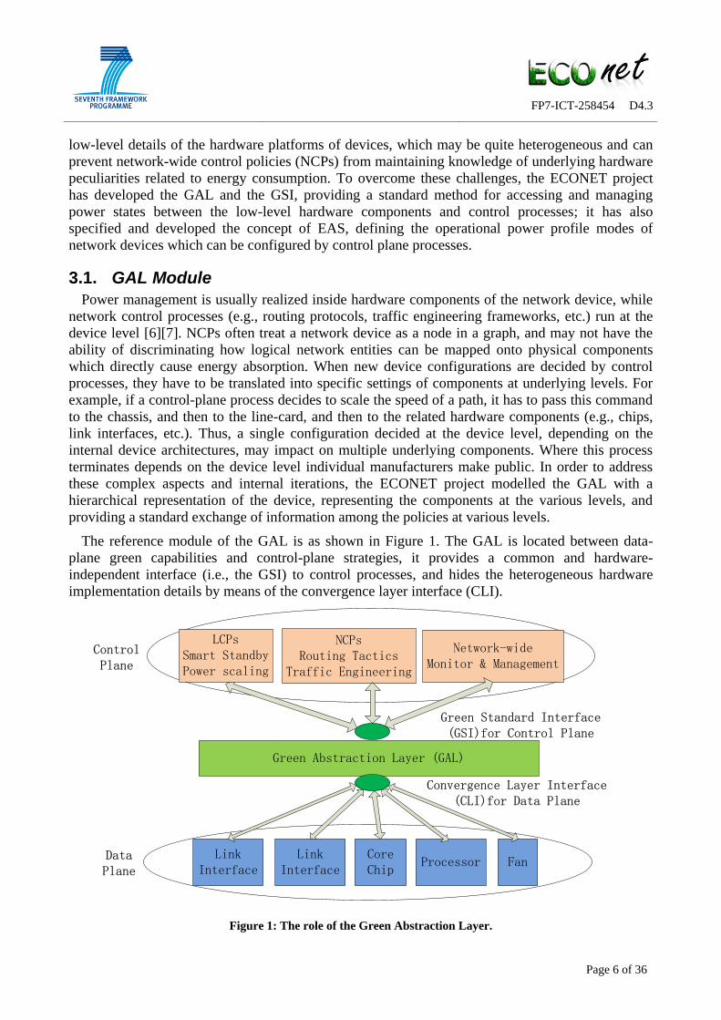
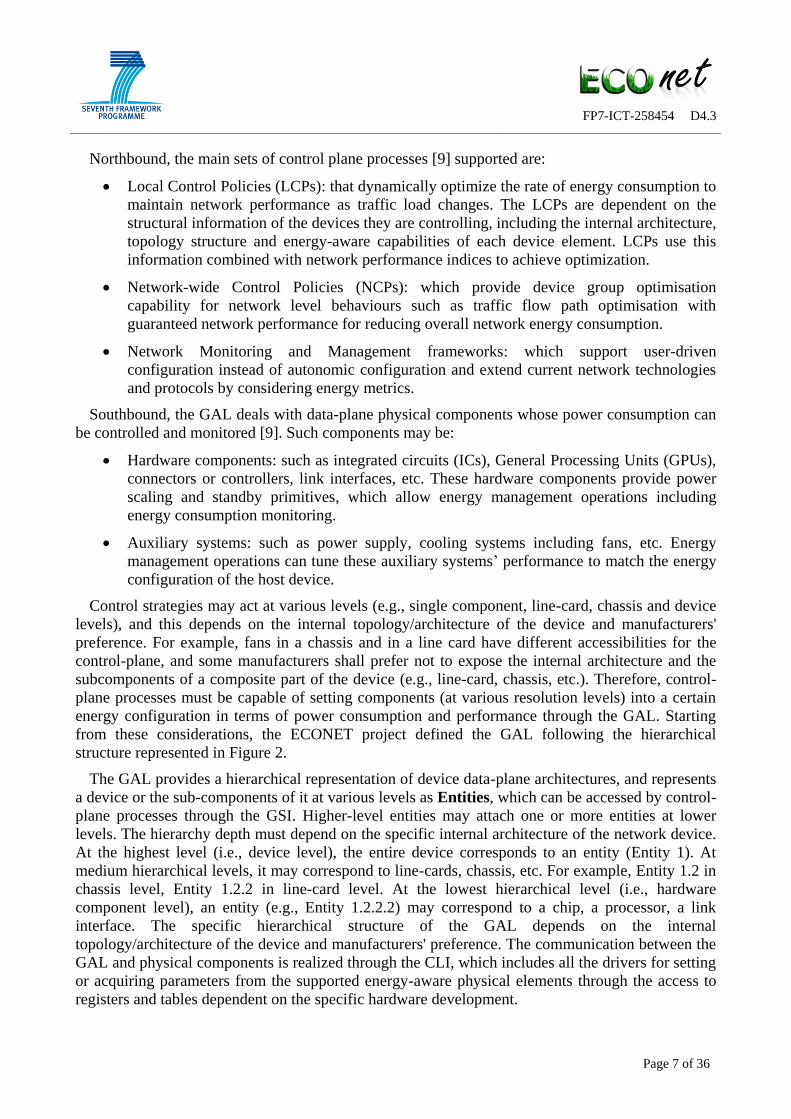

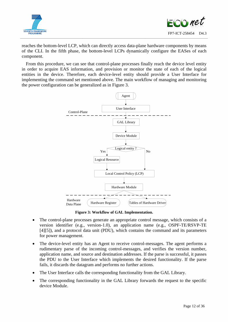

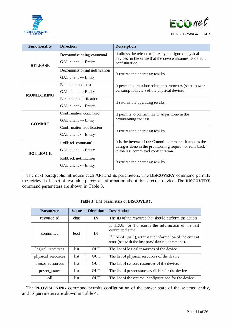
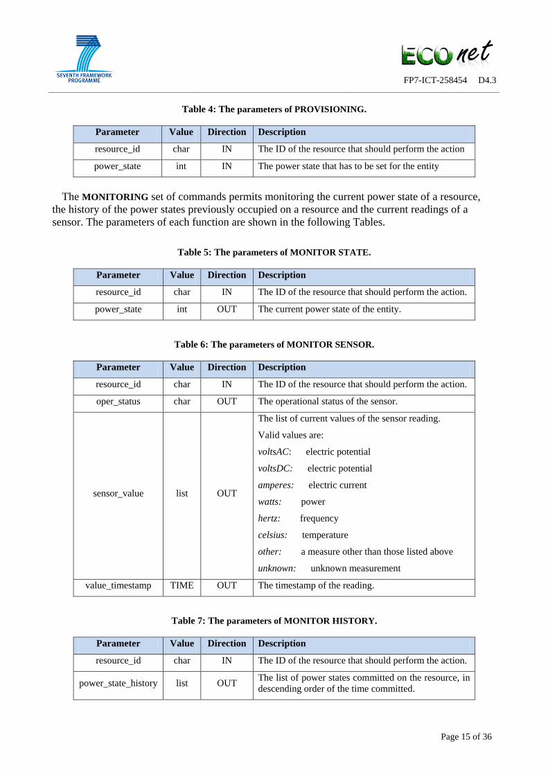

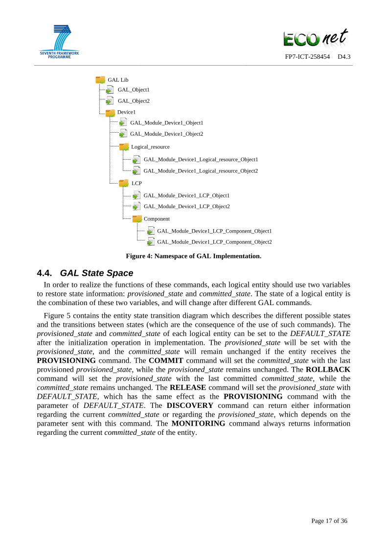
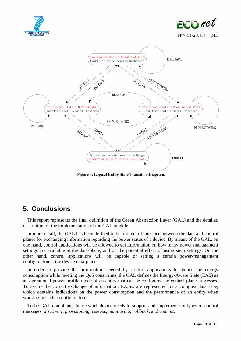
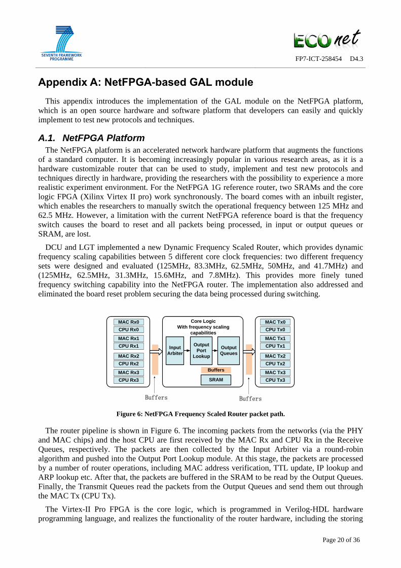
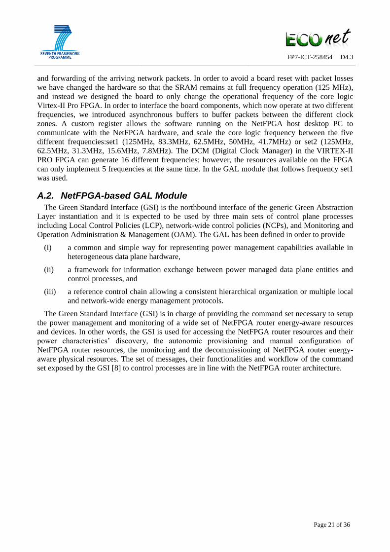

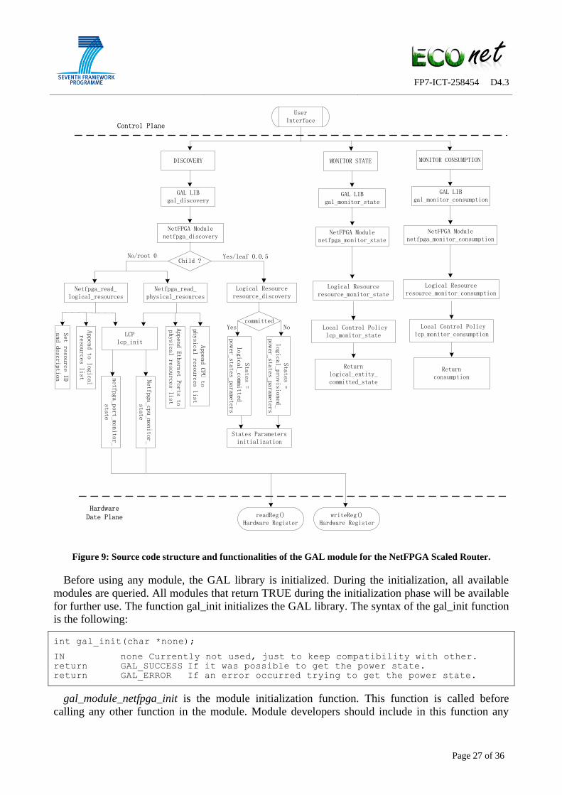
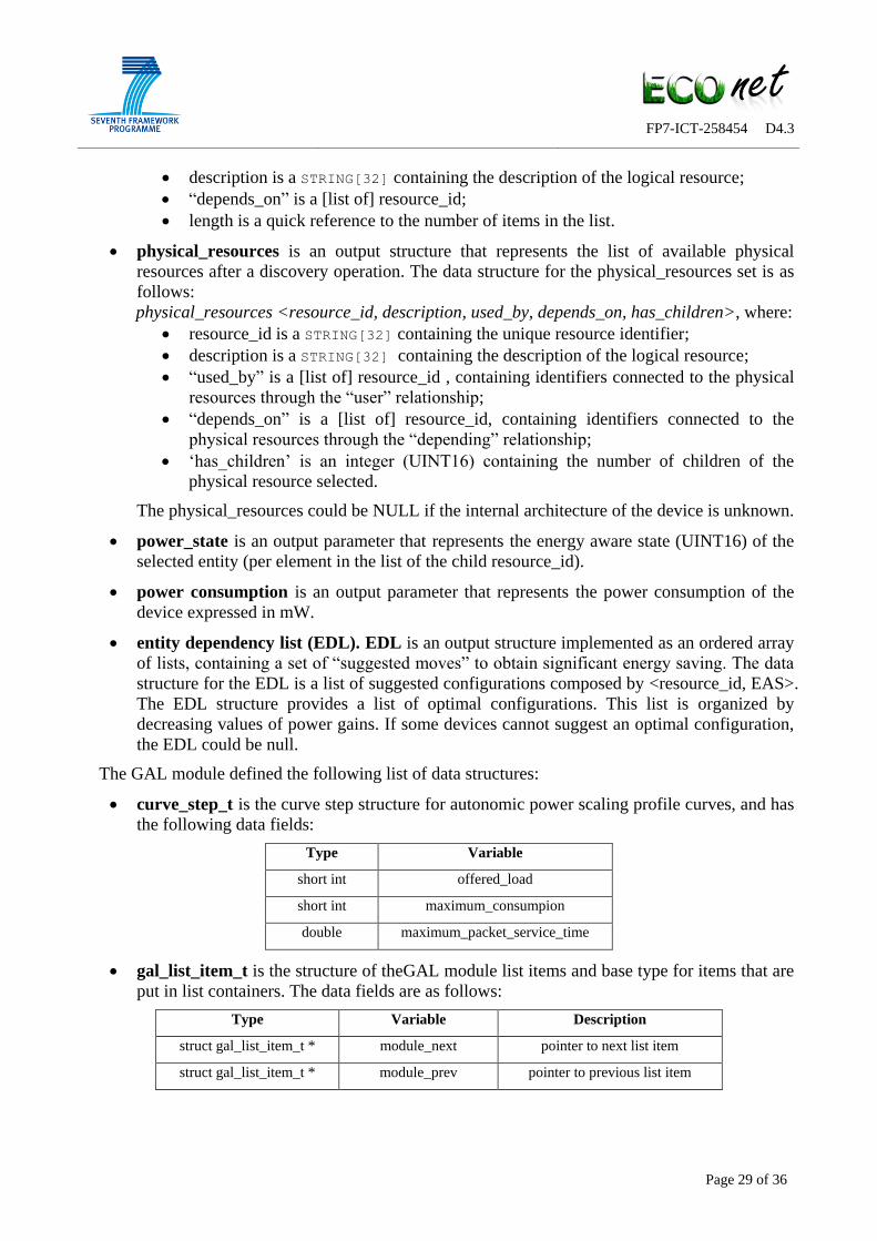
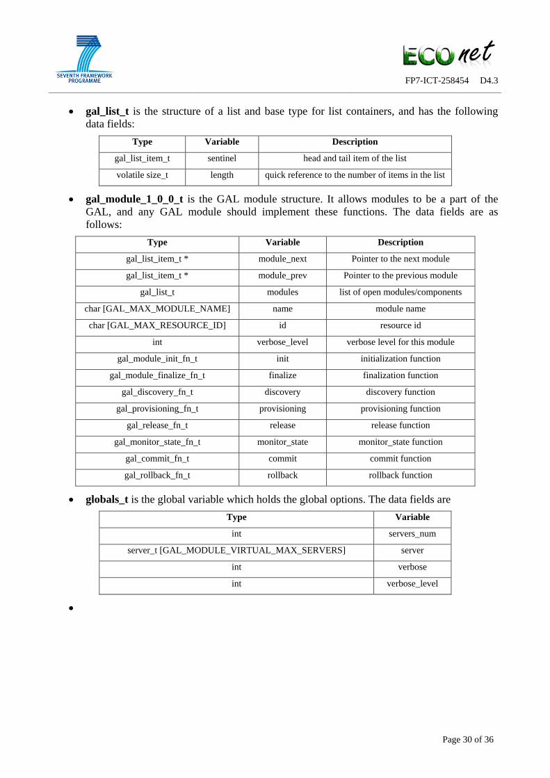


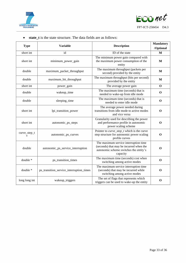


![Power Consumption in Telecommunication Networks: …wardvh.fastmail.fm/papers/2011_commag_vereecken.pdfpower consumption of telecommunication equipment [3], [4]. Next to the characterization](https://static.documents.pub/doc/80x56/5e2fed8fa531b5562a1dd266/power-consumption-in-telecommunication-networks-power-consumption-of-telecommunication.jpg)


