Please record the following information, which is specific to this piece of equipment, in the space provided. Our Parts/Service Department will need these numbers to properly respond to any of your requests.
Instruction Manual: NWB-DC & DC+ IM 9 May, 2017 Model #:___________________________ Serial #____________________________
DISCLAIMER: NOVATEC, Inc. shall not be liable for errors contained in this Instruction Manual nor for misinterpretation of information contained herein. NOVATEC shall not, in any event, be held liable for any special, indirect or consequential damages in connection with performance or use of this information.
TABLE OF CONTENTS 1.0 SALES AND SERVICE ............................................................................................. 5 2.0 SHIPPING AND INSPECTION .................................................................................. 5 3.0 UNPACKING for NovaWheel™ NWB-DC & DC+ DRY/CONVEY MODELS ............. 5
3.1 Unpacking .............................................................................................................. 5 3.1.1 Tools You Will Need for Unpacking: ................................................................ 5 3.1.2 Unpacking Instructions: ................................................................................... 5 3.1.3 List of UNPACKED CONTENTS: .................................................................... 6
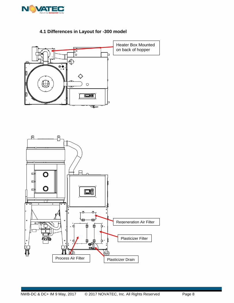
4.0 BASIC COMPONENTS OF NOVATEC NWB-DC DRYER ASSEMBLY ................... 6 4.1 Differences in Layout for -300 model ..................................................................... 8
5.0 ASSEMBLY INSTRUCTIONS ................................................................................... 9 5.1 Prepare/Assemble Machine Mount Receiver ......................................................... 9 5.2 Mount Hopper Receiver & Connect Flex Hose and Pickup Wand ......................... 9 5.3 Positioning the NWB-DC ..................................................................................... 10 5.4 Install Machine Mount Receiver and Connect Flex Hose .................................... 10
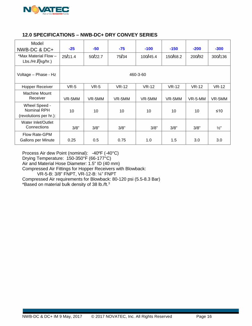
12.0 SPECIFICATIONS – NWB-DC+ DRY CONVEY SERIES ..................................... 16 13.0 FUNCTION CONTROLS ....................................................................................... 17
13.1 Process Temperature Control (Drying Temperature) ......................................... 17 13.2 Regeneration Temperature Control ................................................................... 17 13.3 Process & Regeneration Air Filter Pressure Switches (PS) ............................... 17 13.4 Process Air Dew Point Monitor .......................................................................... 17 13.5 Intelligent Regeneration ..................................................................................... 17 13.6 Conveying Control ............................................................................................. 17
14.0 PRE-OPERATING SYSTEM CHECK ................................................................... 18 14.1 Starting The Dryer ............................................................................................. 18 14.2 Checking Electrical Phase ................................................................................. 18 14.3 Changing From F° to C° .................................................................................... 18
15.0 NovaTouch™ CONTROL ...................................................................................... 19 15.1 System Conventions: ......................................................................................... 19 15.2 Screen Map ....................................................................................................... 20
16.0 INITIAL DRYER STARTUP ................................................................................... 21 16.1 Dryer Pre-Check ................................................................................................ 21 16.2 Explanation of Password Levels ........................................................................ 21 16.3 WELCOME Screen ........................................................................................... 22 Pressing METRIC will change °F to °C. ..................................................................... 22 16.4 Verify/Set Time & Date ..................................................................................... 22 16.5 Auto Start/Stop (Level 2) ................................................................................... 22
20.1 Suggested Maintenance Schedule* ................................................................... 31 20.2 Filters ................................................................................................................. 32 20.3 Process and Regeneration Filters ...................................................................... 32 20.4 Conveying Air Filter ........................................................................................... 32 20.5 Draining Plasticizer ............................................................................................ 32 20.6 Chain and Sprockets ......................................................................................... 33 20.7 Desiccant Rotor ................................................................................................. 33 20.8 Motor Rotation Signal ........................................................................................ 33 20.9 Rotor Replacement ............................................................................................ 34 20.10 Seal Replacement ........................................................................................... 35 20.11 Drive Motor Replacement ................................................................................ 35
21.0 TROUBLE SHOOTING and ERROR MESSAGES ............................................... 36 22.0 WARRANTY .......................................................................................................... 38 FOREWORD This manual is dedicated to the principle that any engineered system will have many elements contributing to the smooth operation of the system, and that these must be understood in order that installation and operation can proceed successfully.
The electrical and mechanical components in the NWB-DC Series dryers have been manufactured, selected and assembled with care to give you excellent service. A wide range of NWB-DC series dryers have been introduced to enable our valued customers to select the right model for their application. These NWB-DC (NovaWheel™ Dry/Convey) series dryers have been designed for beside-the-press drying applications. All components of your NWB-DC series dryers have been carefully engineered and manufactured and have been thoroughly inspected for quality, function and performance.
Before installing this system, please read this manual, review the diagrams and the safety
information. This should save valuable installation and operation time later and will help ensure safe operation and long life.
1.0 SALES AND SERVICE NOVATEC maintains qualified sales, engineering, and service personnel to assist in any way possible. If you have any comments concerning the types of equipment which NOVATEC manufactures that might improve your process, or any questions concerning service, we urge you to contact us. Please have you Model and Serial Number handy.
2.0 SHIPPING AND INSPECTION Although NOVATEC uses reputed carriers to deliver products, it has no control over the products once it leaves the manufacturing facility. Upon receiving the products, thoroughly inspect all equipment inside and out for damage that may have occurred during shipment. If any damage is found, a claim should be filed immediately with your carrier.
NOVATEC thoroughly tests and inspects all products before shipment. You are to make the piping, and electrical connections for final installation and commissioning. If there any problems, shut down the equipment and contact the NOVATEC Technical Service Department.
3.0 UNPACKING for NovaWheel™ NWB-DC & DC+ DRY/CONVEY MODELS
3.1 Unpacking
3.1.1 Tools You Will Need for Unpacking: • Box Cutter • Mallet or hammer • Tin Snips • ½” socket wrench for -150 through -300 model only
3.1.2 Unpacking Instructions: 1- Please look for any signs of damage and report to your carrier immediately. 2- Unpack the Dryer/Hopper
- Remove shrink wrap, and any wood framing attached to the skid. - Cut the metal strapping that secures the Dryer/Hopper to the skid. - Lift the Dryer/Hopper off the pallet and set it in a low-traffic area.
NOTE: All models are shipped with casters installed except the -150 & -200, so while they are being supported by the fork lift, attach one of the supplied casters under each corner of the frame using a ½” socket wrench.
3- Unpack the components to be assembled from separate cartons. - Remove the shrink wrap from the carton(s) and take out the contents. - NOTE: The Hopper Receiver should be set on the floor with the bottom inside
the round fiber tube (supplied) so the bottom flapper is protected by the tube.
5.1 Prepare/Assemble Machine Mount Receiver NOTE: As you proceed with assembly, make sure that all bolts and hose clamps are securely fastened to ensure that there are no air or material leaks in the system. Do not use excessive flex hose but avoid sharp turns as this will hurt the efficiency of the system operation.
5.2 Mount Hopper Receiver & Connect Flex Hose and Pickup Wand
1-A: If Machine Mount Receiver base has not been pre-drilled, remove base from Machine Mount Receiver and drill holes to match machine throat hole pattern and re-attach base to MM Receiver.
1-B: Attach Photo Eye Level Sensor to the bracket provided.
1-C: Connect 24 VDC wiring to twist lock plug. (supplied)
2-A: Remove cover plate from top of Material Hopper (save bolts and washers) then, after removing masking tape from flapper, place Hopper Receiver in hole. Align inlet stub to face direction from where material will be pulled. Fasten the Receiver to the Hopper using the saved ¼” x 20 bolts and washers.
2-B: Place hose clamp over one end of flex hose and push end of the hose on to the material inlet stub on the side of the receiver. Fasten hose clamp securely.
2-C: Cut the flex hose to a length that will allow the 5’ long pickup wand to reach all corners of the bulk container supplying the material to the dryer hopper. Push the cut end of the flex hose over the end of the pickup wand and secure with hose clamp.
2-D: Follow same instructions to attach flex hose running from the vacuum stub on top of the Hopper Receiver to the nearest EPV Dual Station Vacuum Valve Stub extending from the top of the dryer. (See illustration)
1-B
1-C
1-A
Tools You Will Need for Assembly: • Hacksaw to cut PVC flex hose • Flat Blade Screwdriver and/or 5/16” socket for hose clamps • 5/32” Allen wrench to mount Receivers • Drill press and drill bit sized to match mounting holes on machine throat so holes
can be drilled in base of Machine Mount Receiver. (Unless base is pre-drilled) • 6’-8’ Ladder • Tape measure
Hopper Receivers with Blowback are supplied with a male/female twist lock plug to which 115/1/50-60 VAC should be wired. A clean source of 80-120 psi compressed air should be connected to the supplied FNPT fitting. (3/8” on the VR-5 and ¼” on the VR-12)
5.3 Positioning the NWB-DC Roll the NWB-DC into position next to the process machine it will be serving. NOTE: LOCATION Position your NWB-DC Series dryer in a location where material and vacuum hoses will not be disturbed. Allow sufficient distance (at least 2 feet) from the surrounding equipment, so the access doors may be opened to perform routine maintenance on the dryer and for safe operation.
5.4 Install Machine Mount Receiver and Connect Flex Hose
3-A: Bolt the Machine Mount Receiver to the process machine throat with user-supplied bolts. 3-B: Push one end of the flex hose all the way onto the material inlet stub on the side of the receiver and
fasten it securely with a hose clamp (supplied). 3-C: String flex hose to the vacuum purge take-off (attached to the bottom of the hopper) cut it to length
and fasten securely with a hose clamp. 3-D: Attach one end of flex hose to the vacuum inlet stub on top of the Machine Mount receiver and
fasten it securely with a hose clamp. String the flex hose to the farthest EPV Dual Station Vacuum Valve Stub extending from the top of the dryer. Cut flex hose to length and attach it securely to the stub with a hose clamp.
6.0 ELECTRICAL CONNECTIONS The NWB-DC+ Series dryers come from the factory with all control circuits wired and a 10’
power cord. A quick-connect plug should be installed if moving the NWB-DC+ to other process machines is anticipated.
CAUTION • All electrical connections must be made by qualified electricians, per national
and local electrical codes. • Disconnect and lock out the main power source before making the electrical connection.
Turn the Main Disconnect on the electrical panel door to the “OFF” position, lock out the main power source and open the electrical enclosure. Per the electrical diagram, install the main power wire to the main disconnect switch holder and install the ground wire.
Full size electrical drawings are included with this Instruction package for the voltage of the dryer you ordered.
460V/3Ph/60H
NOTE: Please make sure all electrical connections are tight. It is not common but a loose connection is possible after a long truck ride.
NOTE: 3 Phase detection is included on this model. If the connection is not correct, a pop-up alarm will appear on the touch screen upon startup. You should immediately correct this condition.
7.0 PRE-COOLER WATER CONNECTIONS A Cooling Coil is installed in NWB-DC+ series dryers and is required to lower the hopper return temperature and this increases the efficiency of dryer IF THE DRYING TEMPERATURE IS ABOVE 225°F .
Tower, city or chilled water is required at between 40 to 85°F. Connect the cooling water supply and return using flexible hose that is at least 2 feet long, to allow for easy removal of the cooling coil for cleaning. The water flow rates and the required customer connection sizes for different models are shown in the chart below.
NOTE: Processor must use ½” ID water hose to get proper flow. NOTE: Cooling water is required if drying temperature is over 225°F. The process airstream must be connected to an external cooling coil if the drying temperature is below 170°F. Contact Factory for Options.
8.0 COMPRESSED AIR CONNECTION The touch screen control operates a dual station vacuum valve inside the dryer to activate vacuum to either the hopper receiver or the machine mount receiver. A clean compressed air supply (60-90 psi) should be connected to the 1/8” NPT inlet.
Model NWB-XX- DC NWB-XX-DC+
-25
-50
-75
-100
-150
-200
-300
Water Inlet/Outlet Connections
3/8”
3/8”
3/8 “
3/8”
3/8”
3/8”
1/2”
Flow Rate-GPM Gallons per
Minute
0.25
0.5
0.75
1.0
1.5
3.0
3.0
NOTE: ½” O.D. water hose should be used to get proper water flow.
3/8” FNPT Water connections
Compressed Air Connection for Receiver Selection Valve
9.0 HOPPER EXTENSIONS If you ordered a hopper extension, it will be a bolt-on type. The extension will be installed at the factory if the overall height of the unit fits into a standard height truck for shipping. If the unit is too tall for the extension to be factory-mounted, it will be shipped in a separate container and must be installed at the processor’s plant.
10.0 ADJUSTABLE DIFFUSER CONE POSITIONING IMPORTANT FOR PROPER DRYING
We have found that processors can improve the efficiency of their drying process by adjusting the position of the diffuser cone as described below.
You are now ready to proceed to Dryer Setup. See QuickCard attached to dryer.
Use bolts supplied to mount the extension to the
top of the hopper.
Bolt top of hopper to the extension – lift into place - then bolt the extension to
the top of the hopper.
The diffuser cone should be placed in the lower position (shown) when drying virgin resin or resin with a low percentage of regrind. When drying resin with a high % of regrind, spread the clip, raise the cone and place the clip through the lower set of holes.
Clip through upper set of holes for low % of regrind.
Clip through lower set of holes for high % of regrind to raise level of cone.
11.0 PRINCIPLE OF OPERATION The NWB-DC+ Series is designed to convey moisture laden resin from a source container, dry it, and deliver it to the throat of a process machine.
11.1 Resin Drying The NWB-DC and DC+ NovaWheel Series dryers was engineered and designed to effectively remove moisture (in the vapor state) from hygroscopic plastic resins. This process is accomplished by the continuously rotating desiccant wheel and the three air streams (Process, Purge and Regeneration). The Process return air is exposed to an adsorbing media (desiccant wheel) in a sealed air stream, where the desiccant adsorbs the moisture from process air. After the desiccant has adsorbed the moisture, it is exposed to a Regeneration air stream which has been pre-heated to a temperature of about 380°F. (190°C). This causes the moisture to be driven out from the desiccant and prepares it for more moisture adsorption. Now the desiccant media passes through third air stream called purge air stream. Here the desiccant media is cooled down by some of the process air before entering back into the process to provide for better performance. The three air streams (process, regeneration and purge) are separated by special Teflon fabric coated silicon seals. The process air and regeneration air is compressed by using regenerative blowers. The dry air from the dryer is then heated to the desired drying temperature by an electric heater located in the dryer cabinet. The hot dry air enters the hopper at the bottom and removes moisture vapor from the resin in the hopper. The air from the top of the hopper is returned to the dryer, where it is filtered, passed through the desiccant wheel to remove moisture from the air stream and cooled before the process blower sends the air back through the heater and into the bottom of the hopper again in a continuous process.
11.2 Resin Conveying A regenerative blower pulls resin from a bulk container through a pickup wand and flexible hose to an appropriately-sized vacuum receiver where the material is fed into the drying hopper, as needed. As the material passes through the drying hopper it is metered through a vacuum takeoff valve to a machine mount vacuum receiver mounted on the process machine, thereby maintaining a constant flow of dry material to the feed throat.
Process Air dew Point (nominal): -40ºF (-40°C) Drying Temperature: 150-350°F (66-177°C) Air and Material Hose Diameter: 1.5” ID (40 mm) Compressed Air Fittings for Hopper Receivers with Blowback:
VR-5-B: 3/8” FNPT, VR-12-B: ¼” FNPT Compressed Air requirements for Blowback: 80-120 psi (5.5-8.3 Bar) *Based on material bulk density of 38 lb./ft.3
13.0 FUNCTION CONTROLS The NWB-DC+ Series dryers come complete with the following controls:
13.1 Process Temperature Control (Drying Temperature) The Temperature Control is a part of the NovaWheel NovaTouch PLC controller and controls the process outlet temperature as per the set value. In addition, there is a process high temperature limit thermostat that is provided for extra safety. (Refer to the controller section).
13.2 Regeneration Temperature Control The regeneration temperature is controlled by the NovaTouch PLC controller. In addition, there is a regeneration high temperature limit thermostat, which provides extra safety. The regeneration temperature is set at about 380°F. (190°C) and should not be changed.
13.3 Process & Regeneration Air Filter Pressure Switches (PS) The air pressure differential across the process filter and the regeneration filter is monitored and the NovaTouch display will alarm and show when a filter needs to be cleaned or replaced.
These are factory set but often need to be adjusted in the field once the customer loads resin in the hopper. Access pressure switches after opening the side panel of the dryer. Remove Phillips screw that holds clear cover in place (Fig. 1). Turn knob clockwise or counter-clockwise to either increase or decrease.
13.4 Process Air Dew Point Monitor It measures the process air dew point from the dryer.
13.5 Intelligent Regeneration Intelligent Regen constantly monitors the regeneration inlet and outlet temperatures and controls them to optimize the energy and dew point performance of the dryer.
13.6 Conveying Control Provides entry of load/dump times and number of attempted loads before No-Load Alarm is activated plus Blow Back control, if specified.
14.0 PRE-OPERATING SYSTEM CHECK Once material, vacuum hose, water and electrical connections are made, the NWB-DC+ Series dryer should be given a final checkout.
14.1 Starting The Dryer Turn the main disconnect switch to “ON” position to power the dryer. Depress the GREEN START switch on the front panel to start the dryer.
The blowers and heaters are now energized and the desiccant wheel will begin turning and start to dry the return air. It will take several minutes and a couple revolutions of the wheel, for the dew point to get down to the -40° dew point. WARNING: Always use the Green/Red switch to START or STOP the dryer. The Power Disconnect switch should only be used in True Emergency conditions. Repeated use of Power Disconnect can cause dryer component failure.
14.2 Checking Electrical Phase
Your NOVATEC NWB-DC+ Dryer includes Phase Detection. This is particularly important for dryers that may be moved around the plant. When you turn the MAIN Disconnect switch to the ON position, a Pop-Up Alarm will appear on the screen if the connection is not correct. You should immediately correct this condition.
WARNING: Any wiring procedure should only be done by a qualified electrician familiar with three phase electrical wiring.
14.3 Changing From F° to C° The factory setting if F but degrees can be set to C or F on the opening WELCOME screen. (See page 21)
NOTE: All dryers are set to display temperatures in degrees F when shipped.
15.1 System Conventions: All information and data displays will appear two dimensional in configuration and flat. All data entry points or operational features will appear three dimensional in configuration and raised or depressed in appearance depending on their operational position.
Proceed as follows: 1. Touch the relevant IO field on the screen.
The numerical screen keyboard opens and displays the current value. 2. Set the value.
You can only operate keys which are visualized in 3D format. The type of value to be entered determines whether a key is enabled or disabled. The following options for entering values are available:
The current value is deleted when you enter the first character. Enter the value again.
Use the and keys to move the cursor within the current value. You can now edit the characters of the current value or add characters.
Use the key to delete the character to the left of the cursor.
Use the key to change the sign of the value.
Select to view the info text of the IO field.
Select to confirm your entries or cancel them with . Both actions close the screen keyboard.
Numerical Entries: When you touch an IO field on the HMI device touch screen that requires only a numerical entry (Password, Temperature, number of seconds etc.) the following keyboard will appear.
Alpha/Numeric Entries: When you are prompted to enter alphabetical and numerical data (Resin Names/Numbers) this screen will appear:
16.1 Dryer Pre-Check NOTE: Assure voltage, connection and phasing are correct, cooling water is supplied (for drying over 225°F) and thermocouple is inserted in hopper. Connect material source to Hopper Loader Turn Main Disconnect Switch to “ON” position. On first start you should enter Information requested on WELCOME screen.
NOTE: Username setup and password 4444 is required for initial setup. If the proper level of password protection has not been entered prior to attempting changes, the alpha/numeric password entry keypad will appear, prompting the user to input the proper password before changes can be made. Setup username and password will not be required after initial setup except to change other usernames and passwords.
16.2 Explanation of Password Levels User name and Password factory defaults (below) should be updated to ensure proper access. To do that, double-tap the ******** after each Level and enter the new password on the alpha/numeric screen that will appear. You will be prompted to enter the password twice. Press to return to USERS MANAGEMENT screen.
User names and Password factory defaults (below) should be updated to ensure proper access. Level1 : 1111(Operator) – Can choose pre-set recipe and run it. Level2 : 2222 (Production Supervisor) – level1 plus can change recipes, set clock & Auto START/STOP Level3 : 3333 (Maintenance) Same as level 2 setup : 4444 Required for Initial setup
Setup: can change passwords for all levels Level 3 can change Level 3 passwords Level 2 can change Level 2 passwords Level 1 can change Level 1 passwords
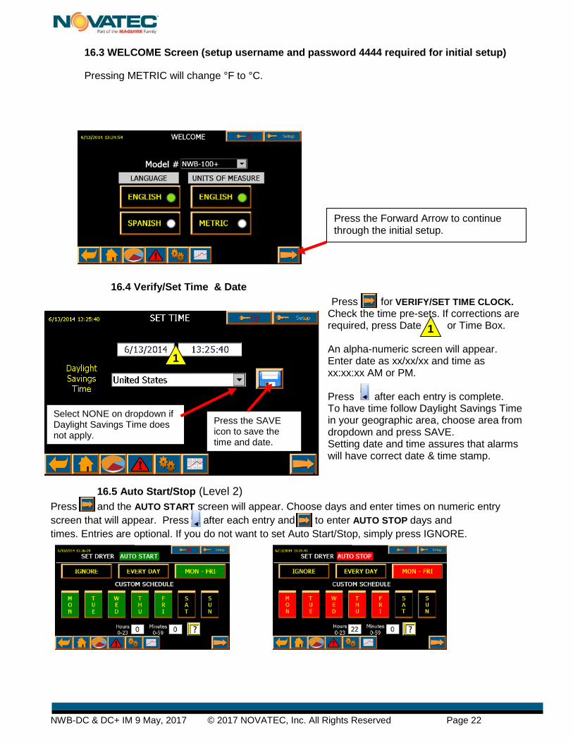
16.3 WELCOME Screen (setup username and password 4444 required for initial setup)
Pressing METRIC will change °F to °C.
16.4 Verify/Set Time & Date Press for VERIFY/SET TIME CLOCK.
Check the time pre-sets. If corrections are required, press Date or Time Box. An alpha-numeric screen will appear. Enter date as xx/xx/xx and time as xx:xx:xx AM or PM. Press after each entry is complete. To have time follow Daylight Savings Time in your geographic area, choose area from dropdown and press SAVE. Setting date and time assures that alarms will have correct date & time stamp.
16.5 Auto Start/Stop (Level 2) Press and the AUTO START screen will appear. Choose days and enter times on numeric entry screen that will appear. Press after each entry and to enter AUTO STOP days and times. Entries are optional. If you do not want to set Auto Start/Stop, simply press IGNORE.
Press the Forward Arrow to continue through the initial setup.
Select NONE on dropdown if Daylight Savings Time does not apply.
17.0 SETTINGS SCREEN (Any level can view) This screen allows changes to be made to previous screens and also allows adjustments to be made to, Alarm Setpoints, User Passwords Advanced Options and Screen Settings.
17.1 Dryer Alarm Settings (level 2) These variables are pre-set at the factory but can be changed by the processor. Setting the values too tightly can cause nuisance alarms.
NOTE: You will go directly to Quick Op screen (page 25) on all future starts.
NOTE: From here on, these icons will appear at the bottom of every screen.
You may want to set passwords for various personnel so they only have access to certain functions. To do that, double-tap the ******** after each Level and enter the new password on the alpha/numeric screen that will appear. You will be prompted to enter the password twice. Press to return to USERS MANAGEMENT screen.
17.3 Advanced Options (level 2 & up) OverDry Protection is Standard on DC+ models and can be activated for moisture sensitive resins like nylon. Water Saver can be activated when an external Cooling oil is employed. Moisture Manager is an option that must be ordered in advance. Alarm Settings are pre-set at NOVATEC but Level3 personnel can adjust the settings.
No security to view these pages but Level 2 and up required to make changes
17.4 Touch Screen Settings You can calibrate “Touch”, Brightness and turn Sound ON or OFF. If the screen is dirty, a button allows you to clean it without disturbing the settings.
18.1 Quick Op Screen NOTE: Assure voltage, connection and phasing are correct, cooling water is supplied (for drying over 225°F) and thermocouple is inserted in hopper. Connect material source to Hopper Receiver. Turn Main Disconnect Switch to “ON” position
Process Temperature is factory set at 160°F. Press temperature button to change temperature or to access RESIN MENU and choose one of the pre-set resins. Press Green “ON” switch to start the Process Heater and Blowers. Note that Process Heater can be turned OFF or ON using buttons on the Quick Op screen. NOTE: DO NOT TURN THE PROCESS HEATER AND BLOWERS ON UNTIL THE HOPPER IS AT LEAST HALF FULL. Press Hopper Receiver icon to access Hopper Loading screen shown below.
18.2 Hopper Loader Setup Press each function and enter value on numeric screen. Press after each entry.
Press on Hopper Loader screen or on Quick Op screen to access Machine Mount Receiver screen (below)
3
4
2
2
5
5
NOTE: Values in Hopper and Machine Receiver screens should be adjusted To optimal values after processing begins. Blowback must be specified when order placed.
18.3 Machine Loader Setup Press each function and enter value on numeric screen. Press after each entry.
Press on Machine Loader 1 screen and again on Hopper Loader 1 screen to return to Quick Ops screen.
18.4 Resin Menu
Access by pressing on QUICK OP screen. Select a material by pressing the button next to a Material. Several materials with appropriate drying temperatures have been pre-loaded into the resin menu.
Up to 10 different recipes can be entered. Note that level1 personnel can choose a recipe and run it but only level 2 personnel can change recipes.
2
NWB-50-DC+
2
Level 1 can select recipe and RUN Level 2 and up can change recipe name, temperature or drying time
Access by pressing the dryer image on the Quick Op screen or on ANY screen. All of the dryer parameters can be monitored.
• Reactivation inlet and outlet temperature
• Process inlet and outlet temperature • System dew point • Calculated desiccant wheel RPH
The graphics on this screen will change appearance in accordance with the mode of operation.
This icon will appear on all screens when there is an alarm. It will flash for an active alarm and show the count for how many alarms are active. It will disappear when the alarms clear or are cleared by operator intervention. Alarm messages will appear as a dropdown box on any screen when the Alarm icon is pressed.
18.5 Dryer Status Screen This screen is widely used by processors
18.6 Message Screen – Alarms
19.0 INSTRUCTIONAL TROUBLESHOOTING SCREENS Examples are shown below.
Press to see those screens.
If you need more information about a
particular alarm, press and a more detailed explanation of the alarm will appear, if available. Some even have photos with instructions on how t d
No Action required. X Reactivation Fan Motor Rotor Drive Motor Process Filter
Clean with compressed air or replace as necessary. Every 2 weeks Regeneration Filter
Conveying Air Filter Plasticizer Drain Drain plasticizer into pan Every 2 weeks
Receiver Filters Clean with compressed air or replace if necessary Every 2 weeks
Process Heater
Compare process temperature setting to hopper inlet temperature
to make sure they are comparable. If they are not - Contact NOVATEC
Service Department.
Every 2 weeks
Hose. Tubing & Clamps Check for leaks or holes. Tighten or replace as necessary. Every 2 months
Hopper Gaskets & Seals Check for leaks Repair or replace as necessary. Every 2 months
Pellet Screen Locate wire mesh at hopper return air outlet and clean with compressed air. Every 2 months
Rotor Drive Chain & Sprockets Lubricate Every 6 months
Rotor Seals Do Not Disturb Except in an Emergency X
Rotor Rotation
Preset at factory-No action required. Rotor speed should be 6-12 rotations/hour. If outside this
parameter, make sure the limit switch hump is re-setting the limit switch.
X
*This schedule may have to be varied depending on the dust level and abrasiveness of the materials you are processing and the number of hours you are operating the dryer each week.
20.2 Filters The filters shipped with the dryer are cleanable. The maintenance interval for the filters depends on the cleanliness of the surroundings and the dust/fines in plastic raw materials. A program should be established to ensure the filters are cleaned.
20.3 Process and Regeneration Filters TURN THE MAIN DISCONNECT SWITCH OFF. On All Models: Turn the yellow knob, lift the filter access cover, remove the lock nut and pull cartridge filter out from housing. Replace the filter or clean it with compressed air, reinstall filter, re-tighten the lock nut, close filter access cover and turn the yellow knob to the locked position. Turn the power ON and restart dryer.
20.4 Conveying Air Filter
Loosen the clips on the Conveying Air Filter and remove it from the canister. Clean it with compressed air or replace as necessary and re-install.
20.5 Draining Plasticizer
Conveying Air Filter Canister
Process Air Filter Access
Regen Air Filter Access
All models have a plasticizer drain on the *back panel. Every 2 weeks (or more often) a pan should be placed under the drain and the valve should be turned to the open position to drain any accumulated plasticizer. Close the valve after draining. *-300 &-400 plasticizer drain on front.
20.7 Desiccant Rotor The state-of-the-art desiccant rotor supplied with NWB-DC+ series dryers will last very long under ideal conditions. Due to the nature of desiccant and honeycomb matrix they make very good filters. The life of desiccant is directly related to the air born contaminates passed through it. Avoid exposure to acidic gases or unusual amounts of dust. Although the desiccant rotor is considered a cleanable/washable media, the preferred method of cleaning is to blow dust out with low pressure compressed air and to reactivate the rotor at a maximum temperature of 380°F (190°C) for 15 minutes. Washing the rotor, although possible, is not recommended as wash water impurities may contaminate the desiccant. Proper filtration and preventing contact with chemicals will greatly improve the life of the desiccant. Inspect the face of the rotor to see that no surface damage has occurred. The rotor should turn smoothly upon the shaft.
.
20.8 Motor Rotation Signal
Check that the wheel rotor is rotating properly and each time a signal goes to the controller, ensure that rotor complete its cycle and the limit switch hump has reset the limit switch provided near the rotor. If the hump is not resetting the limit switch, reset the limit switch toward the rotor.
Desiccant Rotor
Drive Motor
Chain
Tensioner Assembly
Drive Motor
Drive Sprocket
Chain and sprockets should be lubricated every six months.
20.9 Rotor Replacement Desiccant rotor removal is accomplished bas follows: 1. Remove the hex nuts on the Top Plate Assy.. 2. Remove the washers & spring from the Tie Rod. 3. Slide the Top Plate Assembly straight & upward gently. 4. Loosen the Supporting Tie Rod from where rotor is to be moved. 5. Remove the driven sprocket. 6. Slide the Rotor straight & upward, make sure that rotor does not get damaged. 7. Replace the desiccant rotor. To re-install rotor, reverse the above procedure.
The top and bottom silicon PTFE coated fabric flat seals which separates the process from the reactivation purge compartments. Normally they do not require service or replacement. However, should damage occur, or if air leakage is suspected of causing poor performance, the seal should be replaced using the following procedure. 1. Remove rotor from the cassette as explained above. 2. Remove the old seal using knife. Also remove silicon sealant. 3. Clean the plate surface. 4. Apply fresh silicon sealant. 5. Gently press the seal towards the plate, make sure the seal’s section does not get offset 6. After joining the seal to the plate, let it dry for 24 hrs.
NOTE: The smooth Teflon coated side of the seal is always on the top side of the
seal and there should not be any silicon sealant remaining on that side.
20.11 Drive Motor Replacement
Desiccant rotor removal is accomplished as follows: 1. Remove the chain from the drive sprocket. 2. Remove the drive sprocket from the motor shaft. 3. Remove the screws of the motor from the plate. 4. Replace the drive motor. To re-install drive motor, reverse the above procedure.
1. Unit not running Control main circuit breaker tripped. Main power off. Control power interrupted.
Reset the breaker. Check line and main. Check per item as per electrical wiring diagram.
2. Material in hopper melts.
Process temperature controller set too high for material being dried. Temperature probe not installed in process air stream. Process blower rotating in wrong direction. Temperature sensor connection loose or reversed.
Check set temperature for proper drying process temperature. Ensure temperature probe is installed in the dryer outlet, or in the hopper inlet. Change blower rotation. Correct the connection.
3. Reactivation (regeneration) temperature too high.
Reactivation temperature set too High.
Check set-temperature on NWB-DC+ controller. it should be 380°F (190°C)
4. Reactivation (regeneration) heat too low (Rotor not fully reactivating.)
Reactivation thermostat setting too low Reactivation temperature controller set too Low Reactivation heaters faulty.
Adjust thermostat for proper reactivation heat at around 380° F (190°C) Check set temperature on NWB-DC+ microprocessor controller. it should be 380° F. (190°C) Replace heaters.
Clogged Filters Door gasket leaking or damaged. Leak in hose. Hose connection loose. Wrong process temperature for material being dried. Hopper is running almost empty. See #6 below
Inspect, clean/replace filters as necessary Check all gaskets (filter cover, hopper doors, and hopper lids) and repair or replace damaged gaskets. Replace hose Tighten hose connections. Add material to hopper and control the l l hi h 6. High dew point in
process air from dryer into hopper.
High inlet temperature to the wheel rotor (should be less than 150°F per the display). Leaks in the system. High moisture levels in plastic resin being dried in hopper, reducing the drying performance.
Check the cooling water is flowing to the cooling coil and make sure the temperature is below 85°F and at the proper flow. Check the dryer system & hopper for any air leaks & repair as required. Reduce the moisture of the resin being loaded into the hopper. Keep the resin sealed until ready for use, to reduce the amount of moisture being picked up by the resin from the surrounding air.
7. Process blowers not running.
Motor main circuit breaker tripped. Motor overload tripped.
Reset main circuit breaker. Rectify fault reset overload and check motor AMPS are in limit.
8. Dew Point Sensor not working properly.
Not operating High or erratic dew point
Check sensor wiring for tightness & breaks. Check sensor wiring and check tubing to the sensor & sensor for tightness and air leaks. Replace the dew point sensor as required (it should be replaced yearly)
9. Wheel rotor turning but not indexing or showing a RPH speed.
Rotor limit switch not aligned properly. Rotor drive motor defective.
Align the limit switch it should be reset by limit switch hump on each rotation.
Replace motor NOTE: When ALARM message is followed by a ?, press the message for more information.
22.0 WARRANTY WARRANTY – NOVATEC, INC. - Effective Date 8 MAY 2017
NOVATEC, INC. offers COMPREHENSIVE PRODUCT WARRANTIES on all of our plastics auxiliary equipment. We warrant each NOVATEC manufactured product to be free from defects in materials and workmanship, under normal use and service for the periods listed under “Warranty Periods”. The obligation of Novatec, under this warranty, is limited to repairing or furnishing, without charge, a similar part to replace any part which fails under normal use due to a material or workmanship defect, within its respective warranty period. It is the purchaser’s responsibility to provide Novatec with immediate written notice of any such suspected defect. Warranted replacement parts are bil led and shipped freight pre-paid. The purchaser must return the suspect defective part, freight prepaid and with identifying documentation to receive full credit for the part returned. Novatec shall not be held liable for damages or delay caused by defects. No allowance will be made for repairs or alterations without the written consent or approval of Novatec.
The provisions in equipment specifications are descriptive, unless expressly stated as warranties. The liability of Novatec to the purchaser, except as to title, arising out of the supplying of the said equipment, or its use, whether based upon warranty, contract or negligence, shall not in any case exceed the cost of correcting defects in the equipment as herein provided. All such liability shall terminate upon the expiration of said warranty periods. Novatec shall not in any event be held liable for any special, indirect or consequential damages. Commodities not manufactured by Novatec are warranted and guaranteed to Novatec by the original manufacturer and then only to the extent that Novatec is able to enforce such warranty or guaranty. Novatec, Inc. has not authorized anyone to make any warranty or representation other than the warranty contained here. Non-payment of invoice beyond 90 days will invalidate the warranty. A renewed warranty can be purchased directly from Novatec.
Please note that we always strive to satisfy our customers in whatever manner is deemed most expedient to overcome any issues in connection with our equipment. Warranty Periods: Note: All warranty periods commence with the shipment of the equipment to the customer.
5-Year
Resin Drying to Include NovaWheel™ Dryers * Dual Bed Dryers NovaDrier * NDM-5 Membrane Dryer Gas-Fired Process Heaters Gas-Fired Regeneration Heaters Drying Hoppers Central Drying Hopper Assemblies Heater/Blower Units and Hot-Air Dryer Silo Dehumidifiers NovaVac Dryers *
Resin Blending and Feeding to Include WSB Blenders, MaxiBatch & Feeders * Gaylord Sweeper Systems Resin Conveying to Include GSL Series Vacuum Loaders GlassVu Loaders, Receivers and Hoppers Downstream Extrusion Equipment to Include C and NC Bessemer Series Cutters NPS Bessemer Series Pullers NPC Mini Puller/Cutter All NS Series Servo Saws All Cooling and Vacuum Tanks Manufactured by Novatec
3-Year When a Prophecy data plan is activated for VPDB and SVP pumps with PumpSense™, Novatec automatically extends the warranty to 3 years. The data plan must be activated within 60 days after pump shipment, and remain active through the warranty period to maintain extended warranty eligibility. The first 6-months of data plan usage is free from Novatec.
2-Year Central System Controls to Include FlexTouch™ Series Controls FlexXpand™ Series Controls OptiFlex™ Series Controls PLC Communications Modules Greenboard Communications Modules LOGO! Mini PLC Moisture Measurement Equipment to Include MoistureMaster® PET Resin Crystallizers
Resin Conveying and Systems Components to Include VL/VLP Series Loaders VRH, VR, VR-FL & VRP Series Receivers Compressed Air Loaders AL-B Barrel Loader Cyclone Dust Collectors Conveying System Accessories Surge Bins Valves and Accessories Electronic Metal Separators Quick Select Manifolds Tilt Tables Filter Dust Collectors Drawer Magnets
1-Year
Resin Conveying System Components to Include *VPDB Vacuum Positive Displacement Pumps *SVP Vacuum Pumps MVP Vacuum Pumps UltraVac Vacuum Pumps Vacuum Regenerative Blower Pumps Velocity Control Valves
Central System Controls to Include MCS-600 Series Controls – (Distributed I/O) MCS-400 Series Controls CL Silo Manager Infrared Dryers Custom Equipment of any kind unless otherwise specified Railcar Unloading Systems
Exclusions: Routine maintenance/replacement parts are excluded from the warranty. These include, but are not limited to: hoses, desiccant, filters, filter elements, wiper seals, gaskets, dew point sensors, infrared lamps, motors, internal solenoids, fuses and motor brushes. Use with abrasive materials will void the warranty of any standard product. Wear resistant options may be available to extend usable service life with abrasive materials. Novatec reserves the right to limit the warranty if the customer installs replacement parts that do not meet the specifications of the original parts supplied by Novatec.
*Specific Exclusions: 1. NovaDrier warranty is void if coalescing filters are not replaced on a 6-month or yearly basis (per instruction manual)
and/or membrane has been exposed to ozone. 2. NovaVac Dryer -The ability of the canisters to hold vacuum will be compromised if the vacuum seal edge is damaged from mishandling. We do not warranty canisters damaged from improper handling. We do, however, warranty the seals. 3. LOAD CELLS on our WSB’s are covered by Novatec standard warranty as long as they have not been damaged from improper handling. 4. Desiccant Wheel Warranty will be void if the wheel has been exposed to plasticizer, dust or other contaminants as a result of negligence on the part of the processor.
This warranty shall not apply to equipment: 1. Repaired or altered without written approval of NOVATEC unless such repair or
alteration was, in our judgment, not responsible for the failure 2. Which has been subject to misuse, negligence, accident or incorrect wiring by others 3. Warranty is void if processing rates exceed manufacturer-recommended levels or if damage is caused by
ineffective power isolation and/or power spikes/sags or incorrect installation. NOTE: All conditions and content of this warranty are subject to changes without notice.