96
Operating Manual MCON Nitromat

Operating Manual
MCON Nitromat

MCON Nitromat Operating Manual MESA Electronic GmbH
Manufacturer MESA Electronic GmbH
Leitenstraße 26
D-82538 Geretsried-Gelting
Telefon (0 81 71) 76 93-0
Telefax (0 81 71) 76 93-33
Your sales partner
About the contents This manual applies to the MCON Nitromat controller. It
documents the functioning and operation of the device
and the diagnosis of faults.
The guide is intended for all users (operators) and
operator of the MCON Nitromat. It must be accessible to
this group of people and be carefully reviewed before
using the device.
All rights to this documentation, especially the right of reproduction and distribution
and translation reserved by MESA Electronic GmbH, and for the event of copyright
applications. No part of the documentation may be reproduced or modified, copied
or distributed using electronic systems in any form without the express permission of
MESA Electronic GmbH. Subject to errors and technical modifications.
© MESA Electronic GmbH
MESA Electronic GmbH will not be liable for any errors in this documentation.
Liability for any direct or indirect damages caused in connection with the delivery or
use of this documentation is excluded insofar as this is legally permissible.

MCON Nitromat Operating Manual MESA Electronic GmbH
Nitromat 300 EN v1.0 12-2013
Page 3 of 96
Table of Contents
1. User information ........................................................................................................................ 6
1.1 General information ............................................................................................................ 6
1.2 Important safety notes and symbol description .............................................................. 6
1.4 Warranty conditions ............................................................................................................ 8
1.5 Packing and delivery .......................................................................................................... 8
1.6 Standards and regulations ................................................................................................. 8
1.7 Software release versions .................................................................................................. 8
2. Introduction ................................................................................................................................ 9
3. Technical description ............................................................................................................... 11
3.1 Hardware Description ........................................................................................................ 11
3.2. Installation ........................................................................................................................ 18
4. Operating principle .................................................................................................................. 20
5. Configuration procedure ........................................................................................................ 22
5.1 Device powering up .......................................................................................................... 22
6. Menu and display .................................................................................................................... 24
6.1 Screens .............................................................................................................................. 24
6.2 Inserting values ................................................................................................................. 25
6.3 Messages ........................................................................................................................... 26
6.4 Main menu .......................................................................................................................... 27
6.5 Normal View ....................................................................................................................... 29 6.5.1 Bargraph display ........................................................................................................ 31 6.5.2 Graph display ............................................................................................................. 32
6.6 System events ................................................................................................................... 33 6.6.1 Errors .......................................................................................................................... 35 6.6.2 Warnings ..................................................................................................................... 35 6.6.3 Alarms ......................................................................................................................... 36
6.7. Setpoints ........................................................................................................................... 36 6.7.1 Fixed Setpoints .......................................................................................................... 36 6.7.2 Programs .................................................................................................................... 37
7. Programs .................................................................................................................................. 38
7.1 Tracks config ..................................................................................................................... 41
7.2 Program segments ............................................................................................................ 42 7.2.1 Set segment tracks .................................................................................................... 44
8. Control ...................................................................................................................................... 45
8.1 Furnace temperature control .......................................................................................... 45
8.2 Kn control .......................................................................................................................... 49
9. Alarms ....................................................................................................................................... 51
9.1 Analog alarms .................................................................................................................... 51
MCON Nitromat Operating Manual MESA Electronic GmbH
Nitromat 300 EN v1.0 12-2013
Page 4 of 96
9.2 Digital alarm ....................................................................................................................... 55
10. Maintenance ........................................................................................................................... 57
10.1 Measurements ................................................................................................................. 57
10.2 I/O overview ..................................................................................................................... 58 10.2.1 Terminals .................................................................................................................. 58 10.2.2 Digital outputs .......................................................................................................... 58 10.2.3 Digital inputs ............................................................................................................ 59 10.2.4 Analog inputs ........................................................................................................... 60 10.2.5 Analog outputs ......................................................................................................... 60
10.3. Digital outputs assignment ........................................................................................... 61 10.3.1 Digital output assignment constraints .................................................................. 62
11. Analog inputs ......................................................................................................................... 64
11.1 Analog input 1 .................................................................................................................. 64
11.2 Analog input 2 .................................................................................................................. 64
11.3 Analog input 3 .................................................................................................................. 64
11.4 Analog input 4 .................................................................................................................. 64
11.5 Analog input 5 .................................................................................................................. 64
11.6 Analog inputs parameters .............................................................................................. 65
12. Nitriding .................................................................................................................................. 66
12.1 NH3 MFC type .................................................................................................................. 67
12.2 Nitrocarburizing............................................................................................................... 68
12.3 Nitriding settings ............................................................................................................. 68
12.4 Scaling Analog Out ......................................................................................................... 71 12.4.1 AOUT1- MFC NH3 ..................................................................................................... 71 12.4.2 AOUT2 and AOUT3 (MFC N2/CO2) ......................................................................... 72
13. Communication ..................................................................................................................... 73
13.1 Com1 and Com2 .............................................................................................................. 73
13.2 Ethernet communication ................................................................................................ 75
14. User privileges ....................................................................................................................... 77
14.1 Users management ......................................................................................................... 79
15. System settings ..................................................................................................................... 80
15.1 System informations ....................................................................................................... 80
15.2 System functions ............................................................................................................ 81 15.2.1 Touch screen calibration ........................................................................................ 81 15.2.2 Factory settings ....................................................................................................... 82 15.2.3 Parameters backup .................................................................................................. 82 15.2.4 Programs backup..................................................................................................... 82 15.2.5 Firmware update ...................................................................................................... 82
16. Logging ................................................................................................................................... 84
16.1 Logging channels............................................................................................................ 86
17. Control principle .................................................................................................................... 87

MCON Nitromat Operating Manual MESA Electronic GmbH
Nitromat 300 EN v1.0 12-2013
Page 5 of 96
17.1 PID control ....................................................................................................................... 87
17.2 Discrete control output ................................................................................................... 90
17.3 On/Off control .................................................................................................................. 91
17.4 Analog control ................................................................................................................. 92
18. Specifications ........................................................................................................................ 93
18.1 Isolation diagram............................................................................................................. 96

MCON Nitromat Operating Manual MESA Electronic GmbH
MCON Nitromat EN v1.0 04-2013
Page 6 of 96
1. User information
Please read carefully this instruction before operating the device. Here you
can find important information for adequate using regarding operators safety
and correct device working.
1.1 General information
For correct and safe operate device should be used according to the
instructions given by the producer. Correct operating also depends on proper
handling, storage, transport and maintains
Knowing of warning symbols is needed for proper handling of the device.
Among the other, these instructions are defining the area of device usage and
needed operator qualification.
Because of the limited size of the manual, there still are some details
concerning installation and usage of the device, which are not covered. Thus,
for additional explanation, customer should contact producer’s technical
support.
1.2 Important safety notes and symbol description
It is extremely important to know the meaning of symbols which are appearing
in the manual. Safety notes and warnings are intended to prevent operator
hazard situations and damage of the device or working environment.
Symbol explanations are given as follow:
DANGER!
Means directly life danger, seriously
body injuries and equipment damage.

MCON Nitromat Operating Manual MESA Electronic GmbH
MCON Nitromat EN v1.0 04-2013
Page 7 of 96
WARNING!
Means possible death danger, danger
of serious body injuries and equipment
damage.
CAUTION!
Means possible danger of slight body
Injuries and danger of serious device or
equipment damage.
CAUTION!
Means danger of serious device or
equipment damage.
NOTE
Refer to the important information on
which should pay attention.
Proper usage
Device should be used only in purposes which are described in this manual.
Information about the field and way of usage can be found in chapters 2.
Introduction, 3. Technical specification and 4. Operating principle.
Qualified operators
Only qualified personal should operate this device. Qualified personal are
persons which are familiar with installation, mounting and handling this
device. Also they should be trained for work with the devices and systems
concerning safety standards for electronic equipment, gases at high
pressures, aggressive and dangerous environment.
MCON Nitromat Operating Manual MESA Electronic GmbH
MCON Nitromat EN v1.0 04-2013
Page 8 of 96
Installation, connection to electrical power supply, connection to gas
installation, commissioning and maintenance must be done by qualified
operators.
1.4 Warranty conditions
Content of this manual is not a part of any agreement, commitment or
statutory right. All commitment on the producer’s part is contained in the
respective sales contract which also contains completely warranty conditions.
The warranty conditions are not changed with the content of this manual.
1.5 Packing and delivery
Content of the shipment is listed in the documents associated to the shipment,
according to the terms of contract. Please, after receiving, check if the
shipment is complete and undamaged.
1.6 Standards and regulations
Specification and production of this device are done according to the
harmonized European standards. Where European standards could not be
applied, the standards of Federal Republic of Germany were applied.
When using this device outside the area where these standards are applied,
the appropriate standards of the country of use should be observed.
1.7 Software release versions
Actual software version can be seen from menu, see Chapter 18.1 System
Informations. This user manual describes software version 1.00.

MCON Nitromat Operating Manual MESA Electronic GmbH
MCON Nitromat EN v1.0 04-2013
Page 9 of 96
2. Introduction Nitriding is thermo-chemical process for hardening the surface layer of steel
workpiece. Nitriding is applied in order to increase the resistance to wearing
and corrosion and to improve the dynamical hardness of steel parts. The
surface layer provides the resistance to wear and corrosion while the diffuse
layer located below, preserve hardness. Process temperature during nitriding
is between 480ºC and 580ºC while it last from 1 up to 100 hours. Interconnect
layers, made in gas nitriding process, are composed of intermetallic
connection of iron and nitrogen (ε- and γ'- iron nitrides) which, depending of
process duration, can achieve depth of 10...30 µm and can have high point of
hardness with low brittle characteristic. But molding of this layer can be
completely avoided. A diffusion zone can be found below which achieve up to
0.8mm in depth into material. Here the nitrogen is diffusing into internal iron
structure and with alloying component like Cr, Mo, Ti, Al, V creates special
nitrides. These special nitrides are very important for high hardness and wear
resistance of alloyed materials.
300 400 500 600 700 800
0.01
0.1
1
10
ε - Nitrid.
γ’ - Nitrid.
γ - Mix. crystal
α - Mixed crystal
Temperature (ºC)
Nit
rid
ing
nu
mb
er
- K
n
figure 1. The conditions for originating the specific phases of iron nitrides
Nitrocarburizing is thermo-chemical process for doping and hardening the
surface layer of workpiece. Carburizing is performed in gas atmosphere at
temperature between 500ºC and 630ºC in mixture of gases which can release
nitrogen (for example ammonia) or carbon (for example carbon dioxide). The
MCON Nitromat Operating Manual MESA Electronic GmbH
MCON Nitromat EN v1.0 04-2013
Page 10 of 96
aim is to increase the resistance to wearing and corrosion of low and medium
alloyed steels.
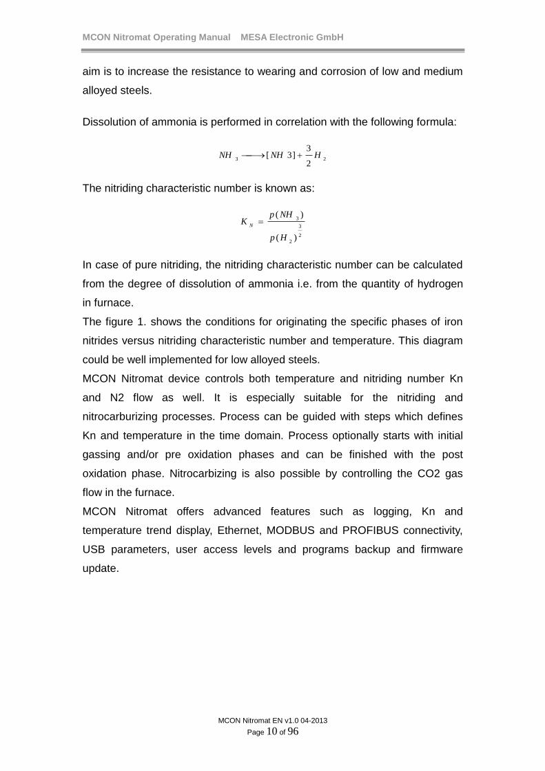
Dissolution of ammonia is performed in correlation with the following formula:
232
3]3[ HNHNH
The nitriding characteristic number is known as:
2
3
2
3
)(
)(
Hp
NHpK
N
In case of pure nitriding, the nitriding characteristic number can be calculated
from the degree of dissolution of ammonia i.e. from the quantity of hydrogen
in furnace.
The figure 1. shows the conditions for originating the specific phases of iron
nitrides versus nitriding characteristic number and temperature. This diagram
could be well implemented for low alloyed steels.
MCON Nitromat device controls both temperature and nitriding number Kn
and N2 flow as well. It is especially suitable for the nitriding and
nitrocarburizing processes. Process can be guided with steps which defines
Kn and temperature in the time domain. Process optionally starts with initial
gassing and/or pre oxidation phases and can be finished with the post
oxidation phase. Nitrocarbizing is also possible by controlling the CO2 gas
flow in the furnace.
MCON Nitromat offers advanced features such as logging, Kn and
temperature trend display, Ethernet, MODBUS and PROFIBUS connectivity,
USB parameters, user access levels and programs backup and firmware
update.

MCON Nitromat Operating Manual MESA Electronic GmbH
MCON Nitromat EN v1.0 04-2013
Page 11 of 96
3. Technical description
3.1 Hardware Description
MCON Nitromat device is packed in standard DIN ¼ package. Dimensions
are 118mm x 96mm x 96mm.
figure 2. MCON Nitromat controller
Front panel of the device contains TFT touch screen, USB port, status LED’s
and keys. On the rear side there are connections for analog inputs and
outputs, digital inputs and outputs, communications and power supply.

MCON Nitromat Operating Manual MESA Electronic GmbH
MCON Nitromat EN v1.0 04-2013
Page 12 of 96
1.8
1.6
1.4
1.2
1.81.8
1.0
0.8
0.6
0.4
0.2
0.0
Furnace control- Graph
WT=850ºC WC=850%T=828ºC C=850%
1100
1000
900
800
700
600
500
400
300
200
03:15:02 03:15:32
(1)(2)
(3)(4)
(5)
(6)
(7)
(8)
Nitromat 300
figure 3. MCON Nitromat front panel
1 – USB port
2 – Escape key
3 – Communication activity LED
4 – Key Down
5 – Alarm1 (dout1) status
6 – Key Up
7 – Alarm2 (dout2) status
8 – Enter Key
figure 4. MCON Nitromat back side

MCON Nitromat Operating Manual MESA Electronic GmbH
MCON Nitromat EN v1.0 04-2013
Page 13 of 96
On the next table are listed all terminal outputs signals:
TERNINAL # Signal Description
1 L Power Supply L 220V
Power Supply N 220V 2 N
3 REL2 NO
REL 2, 5A – DIGOUT2 4 REL2 COM
5 REL2NC
6 REL1 NO
REL 1, 5A – DIGOUT1 7 REL1_COM
8 REL1 NC
9 RXA
RS 485/422 isolated
10 RXB
11 TXB / RS485 B
12 TXA / RS485 A
13 GND_ISOLATED
14 GND
RS485 uninsulated 15 A
16 B
17 IN1+ AIN 1
(thermocouple – furnace temperature) 18 IN1-
19 IN2+ AIN 2
(4-20 mA – H2 sensor) 20 IN2-
21 IN3+ AIN 3
(4-20 mA – MFC N2) 22 IN3-
23 IN4V (not used) AIN 4
(4-20 mA – MFC NH3) 24 IN4N (IN4-)
25 IN4A (IN4+)
26 IN5V (not used) AIN 5
(4-20 mA – MFC CO2) 27 IN5N (IN5-)
28 IN5A (IN5+)
29 AOUT GND AOM MODULE1
(MFC NH3, MFC N2) 30 AOUT1 I

MCON Nitromat Operating Manual MESA Electronic GmbH
MCON Nitromat EN v1.0 04-2013
Page 14 of 96
31 AOUT1 U (not used)
32 AOUT2 I
33 AOUT2 U (not used)
34 AOUT GND
AOM MODULE2 (MFC CO2)
35 AOUT3 I
36 AOUT3 U (not used)
37 AOUT4 I (not used)
38 AOUT4 U (not used)
39 M3_1
MODULE 3 (REL1,REL2,REL3, DIGITAL INPUT)
40 M3_2
41 M3_3
42 M3_4
43 M3_5
44 M3_6
45 M4_1
MODULE 4 (REL1,REL2, DIGITAL INPUT)
MODULE
4,5 and 6
OC12
46 M4_2
47 M4_3
48 M4_4
49 M4_5
50 M5_1
MODULE 5 (REL1,REL2, DIGITAL INPUT)
51 M5_2
52 M5_3
53 M5_4
54 M5_5
55 M6_1
MODULE 6 (REL1,REL2,REL3, DIGITAL INPUT)
56 M6_2
57 M6_3
58 M6_4
59 M6_5
60 M6_6
MCON Nitromat is highly flexible with inputs and outputs and their number
depends on built in modules. There are several module types which can be

MCON Nitromat Operating Manual MESA Electronic GmbH
MCON Nitromat EN v1.0 04-2013
Page 15 of 96
ordered and installed on certain positions so user can customize I/O
peripherals according to custom requirements.
REL1 module – 4 relays, 3A 250V, 4NO (normally open) contacts and one
common (COM) contact.
Re
l1
Re
l2
Re
l3
Re
l4
Co
m
MODULE connection
Terminal connection
Rel1 Mn_1
Rel2 Mn_2
Rel3 Mn_3
Rel4 Mn_4
COM Mn_5
REL2 module – 2 relays, 5A 250V, 2NO and 1NC (normally closed) contacts
and 2 COM contacts.
Re
l1
Re
l2
MODULE connection
Terminal connection
Rel1 Mn_1
Rel1 Mn_2
Rel2 Mn_3
Rel2 Mn_4
Rel2 COM Mn_5
REL3 module – 3 relays, 3A 250V, 3 NO and 3 COM contacts.
Re
l1
Re
l2
Re
l3
MODULE connection
Terminal connection
Rel1 Mn_1
Rel1 Mn_2
Rel2 Mn_3
Rel2 Mn_4
Rel3 Mn_5
Rel3 Mn_6

MCON Nitromat Operating Manual MESA Electronic GmbH
MCON Nitromat EN v1.0 04-2013
Page 16 of 96
DIGIN module – 4 isolated digital inputs with common ground
Din
p1
Din
p2
Din
p3
Din
p4
gn
d
MODULE connection
Terminal connection
Dinp1 Mn_1
Dinp2 Mn_2
Dinp3 Mn_3
Dinp4 Mn_4
gnd Mn_5
AOM module - Two independent isolated analog outputs with 10V voltage
and 20mA current output in parallel.
I- c
h1
U-c
h1
I- c
h2
U-c
h2
gn
d
I
I
ch1 ch2
MODULE connection
Terminal connection
I-ch1 Mn_1
U-ch1 Mn_2
I-ch2 Mn_3
U-ch2 Mn_4
gnd Mn_5
OC12 module – 12 open collector outputs for connecting with relay box RL45
or external relays.
MODULE connection
Terminal connection
OUT1 29/45
OUT2 30/46
OUT3 31/47
OUT4 32/48
OUT5 33/49
OUT6 34/50
OUT7 35/51
OUT8 36/52
OUT9 37/53
MCON Nitromat Operating Manual MESA Electronic GmbH
MCON Nitromat EN v1.0 04-2013
Page 17 of 96
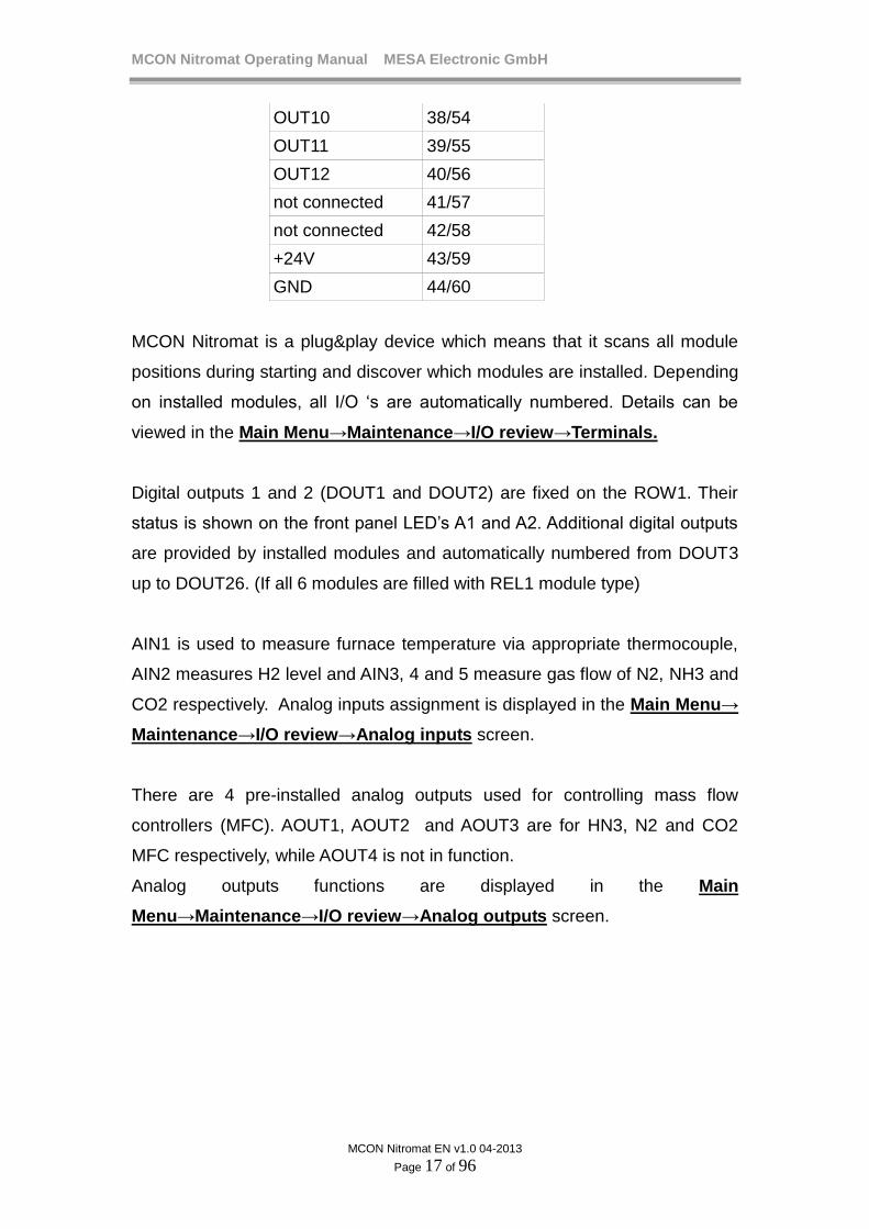
OUT10 38/54
OUT11 39/55
OUT12 40/56
not connected 41/57
not connected 42/58
+24V 43/59
GND 44/60
MCON Nitromat is a plug&play device which means that it scans all module
positions during starting and discover which modules are installed. Depending
on installed modules, all I/O ‘s are automatically numbered. Details can be
viewed in the Main Menu→Maintenance→I/O review→Terminals.
Digital outputs 1 and 2 (DOUT1 and DOUT2) are fixed on the ROW1. Their
status is shown on the front panel LED’s A1 and A2. Additional digital outputs
are provided by installed modules and automatically numbered from DOUT3
up to DOUT26. (If all 6 modules are filled with REL1 module type)
AIN1 is used to measure furnace temperature via appropriate thermocouple,
AIN2 measures H2 level and AIN3, 4 and 5 measure gas flow of N2, NH3 and
CO2 respectively. Analog inputs assignment is displayed in the Main Menu→
Maintenance→I/O review→Analog inputs screen.
There are 4 pre-installed analog outputs used for controlling mass flow
controllers (MFC). AOUT1, AOUT2 and AOUT3 are for HN3, N2 and CO2
MFC respectively, while AOUT4 is not in function.
Analog outputs functions are displayed in the Main
Menu→Maintenance→I/O review→Analog outputs screen.

MCON Nitromat Operating Manual MESA Electronic GmbH
MCON Nitromat EN v1.0 04-2013
Page 18 of 96
3.2. Installation
Before use the device it must be installed in dry environment with ambient
temperature up to 70 ºC.
Put out the terminals from the back panel and connect the wires.
On ROW1 connect wires for the power supply, DOUT1 (A1) and 2 and
communication.
On ROW2 terminal connect sensors for measurement according to the next
rules:
Analog inputs connections: - on the AIN1 position , connect Thermocouple (B,C,E,J,K,L,M,N,R , S or
T type)
- on the AIN2 position, connect output from NT46 device to measure
H2%
- on the AIN3 position connect output from N2 MFC
- on the AIN4 position connect output from NH3 MFC
- on the AIN5 position connect output from CO2 MFC
Analog outputs connections:
- Connect AOUT1 to the MFC NH3 input (if analog control output is
used)
- Connect AOUT2 to the MFC N2 input
- Connect AOUT3 to the MFC CO2 input
NOTE
AIN5 and AOUT3 are used only if nirocarburizing is required.
For pure nitriding they are not important.
NOTE
When pulse control is used, there is no need to connect analog
output because instead MFC, a valve on/off time is used to
control the flow.

MCON Nitromat Operating Manual MESA Electronic GmbH
MCON Nitromat EN v1.0 04-2013
Page 19 of 96
NITROMAT 300
MFC NH3
(4-20 mA)
out in
MFC N2
(4-20 mA)
out in
MFC CO2
(4-20 mA)
out in
AIN4 AOUT1 AIN3 AOUT2 AIN5 AOUT3
NT46
(4-20 mA)
AIN2
H2 probe
AIN1
Thermocouple
figure 5. Connecting mass flow controllers, H2 sensor and thermocouple
Digital outputs connections:
- One digital output is used for the small/great NH3 MFC valve. High
state means that great NH3 MFC is used.
- One digital output is for the nitrocarburizing track.
- One digital output for oxidating track
- One digital output for purging track
- One digital output for initial gassing track
- Up to 16 digital outputs are used as control tracks for program.
- Up to 3 digital outputs to for valve control (when MFC not used)
- One or two digital outputs for temperature control (heating and cooling)
- Up to 4 digital outputs can be assigned to alarms
Digital inputs connections
- DIGIN1 TO DIGIN4 for program starting or alarm disabling
(for details go to chapters “Alarms” and “Programs”)(
MCON Nitromat Operating Manual MESA Electronic GmbH
MCON Nitromat EN v1.0 04-2013
Page 20 of 96
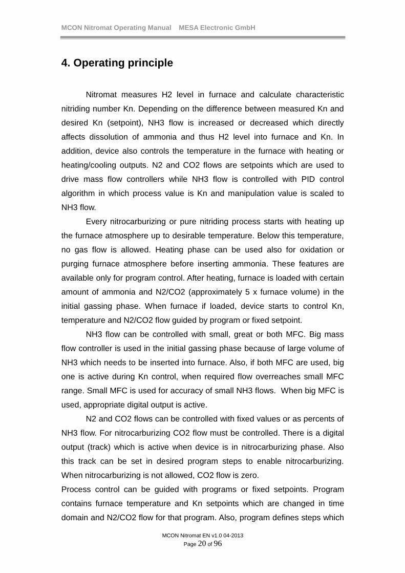
4. Operating principle
Nitromat measures H2 level in furnace and calculate characteristic
nitriding number Kn. Depending on the difference between measured Kn and
desired Kn (setpoint), NH3 flow is increased or decreased which directly
affects dissolution of ammonia and thus H2 level into furnace and Kn. In
addition, device also controls the temperature in the furnace with heating or
heating/cooling outputs. N2 and CO2 flows are setpoints which are used to
drive mass flow controllers while NH3 flow is controlled with PID control
algorithm in which process value is Kn and manipulation value is scaled to
NH3 flow.
Every nitrocarburizing or pure nitriding process starts with heating up
the furnace atmosphere up to desirable temperature. Below this temperature,
no gas flow is allowed. Heating phase can be used also for oxidation or
purging furnace atmosphere before inserting ammonia. These features are
available only for program control. After heating, furnace is loaded with certain
amount of ammonia and N2/CO2 (approximately 5 x furnace volume) in the
initial gassing phase. When furnace if loaded, device starts to control Kn,
temperature and N2/CO2 flow guided by program or fixed setpoint.
NH3 flow can be controlled with small, great or both MFC. Big mass
flow controller is used in the initial gassing phase because of large volume of
NH3 which needs to be inserted into furnace. Also, if both MFC are used, big
one is active during Kn control, when required flow overreaches small MFC
range. Small MFC is used for accuracy of small NH3 flows. When big MFC is
used, appropriate digital output is active.
N2 and CO2 flows can be controlled with fixed values or as percents of
NH3 flow. For nitrocarburizing CO2 flow must be controlled. There is a digital
output (track) which is active when device is in nitrocarburizing phase. Also
this track can be set in desired program steps to enable nitrocarburizing.
When nitrocarburizing is not allowed, CO2 flow is zero.
Process control can be guided with programs or fixed setpoints. Program
contains furnace temperature and Kn setpoints which are changed in time
domain and N2/CO2 flow for that program. Also, program defines steps which

MCON Nitromat Operating Manual MESA Electronic GmbH
MCON Nitromat EN v1.0 04-2013
Page 21 of 96
performs oxidation or purging. For this purpose is used program tracks which
user can set.
MCON Nitromat has 2 control loops used to control temperature, and Kn. For
both loops there are separate control parameters which are organized in
presets. Every loop has 3 presets which hold PID parameters and user can
chose which one is active. N2 and CO2 flows are controlled directly via MFC.
During the measurement/control, device also checks all alarms and activates
associated digital output if the alarm is activated.
Also user can start logging of the measured data and stop the logging
automatically or manually and transfer file with logged data to USB stick.
Depending of the communication configurations MCON Nitromat can send the
measured data and statuses via MODBUS or PROFIBUS and also can obtain
parameters and commands.
MCON Nitromat Operating Manual MESA Electronic GmbH
MCON Nitromat EN v1.0 04-2013
Page 22 of 96
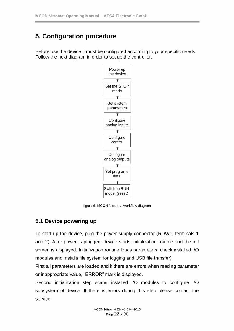
5. Configuration procedure
Before use the device it must be configured according to your specific needs. Follow the next diagram in order to set up the controller:
figure 6. MCON Nitromat workflow diagram
5.1 Device powering up
To start up the device, plug the power supply connector (ROW1, terminals 1
and 2). After power is plugged, device starts initialization routine and the init
screen is displayed. Initialization routine loads parameters, check installed I/O
modules and installs file system for logging and USB file transfer).
First all parameters are loaded and if there are errors when reading parameter
or inappropriate value, “ERROR” mark is displayed.
Second initialization step scans installed I/O modules to configure I/O
subsystem of device. If there is errors during this step please contact the
service.
MCON Nitromat Operating Manual MESA Electronic GmbH
MCON Nitromat EN v1.0 04-2013
Page 23 of 96
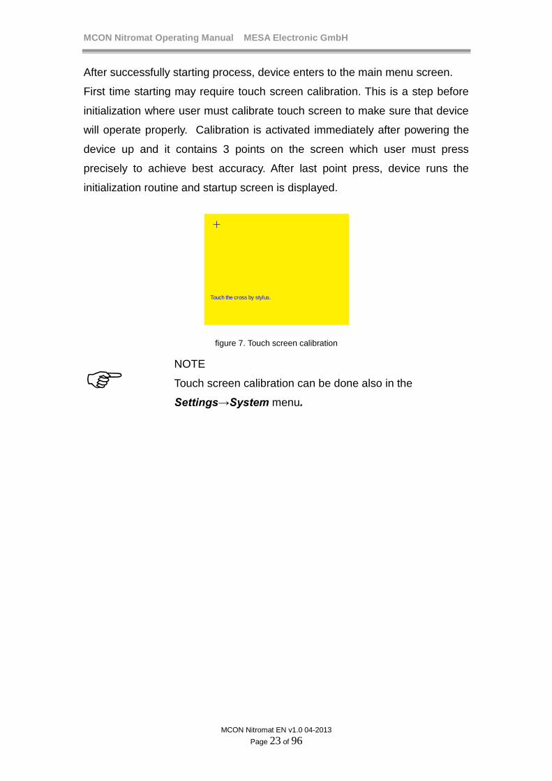
After successfully starting process, device enters to the main menu screen.
First time starting may require touch screen calibration. This is a step before
initialization where user must calibrate touch screen to make sure that device
will operate properly. Calibration is activated immediately after powering the
device up and it contains 3 points on the screen which user must press
precisely to achieve best accuracy. After last point press, device runs the
initialization routine and startup screen is displayed.
Touch the cross by stylus.
figure 7. Touch screen calibration
NOTE
Touch screen calibration can be done also in the
Settings→System menu.

MCON Nitromat Operating Manual MESA Electronic GmbH
MCON Nitromat EN v1.0 04-2013
Page 24 of 96
6. Menu and display
6.1 Screens
User has 2 options to interact with the device. One is touch screen where user
can directly press desired buttons and second is 4 key keypad.
Keyboard keys (DOWN) and (UP) are used to change a focus among
the screen buttons. Key (ESC) returns to the previous screen and key
(ENTER) press the focused button
Focused button has green color instead of blue color of unfocused button.
Focused and nonfocused buttons : Button Button
All screens in the MCON Nitromat menus consist of several elements:
(1) Exit/return button returning to the previous screen or menu
(2) Button – pressing this button to activate some action or enter to
menu/screen
(3) Input button– pressing this button to open the keyboard screen for
entering parameter value
(4) Checkbox button– check/uncheck an option
(5) Next button – goes to the next page of the screen/menu
(6) Titlebar – shows the name of the current menu/screen
Caption
Button
Input value
Checkbox
(5)
(6)
(1)
(2)
(3)
(4)
Nitromat 300
figure 8. Basic screen elements

MCON Nitromat Operating Manual MESA Electronic GmbH
MCON Nitromat EN v1.0 04-2013
Page 25 of 96
6.2 Inserting values
Parameter values are inserted in the keyboard screen which is displayed after
pressing the input button. Parameter can be numeric value, text, selection or
date/time values.
For the numeric values on the screen are shown minimum (MIN) and
maximum allowed (MAX) value for the parameter, parameter unit and
parameter default value.
ESC - escape from keyboard with no changing the value
ENT - confirm entered value and exit
<- - delete letter or number
Default - enter default value for parameter and exit from the keyboard screen
1 2
54
3
6
8 97
ENT 0ESC<- . -
Default
Parameter name value
Unit: ºC
MIN: 500
MAX: 950
800
abc
jklghi
def
mno
tuv wxyzpqrs
ENT _ESC<- ABC
Parameter name value
figure 9. Keyboard screen
There are parameters with predefined values which are set by choosing one
value from a list. After selecting desired parameter value, to confirm press ü
button, or button cancel selection.
Parameter name
Option 1
ü
Option 2
Option 3 Option 4
Option 5 Option 6
Option 7 Option 8
Option 9 Option 10
figure 10. Options screen
MCON Nitromat Operating Manual MESA Electronic GmbH
MCON Nitromat EN v1.0 04-2013
Page 26 of 96
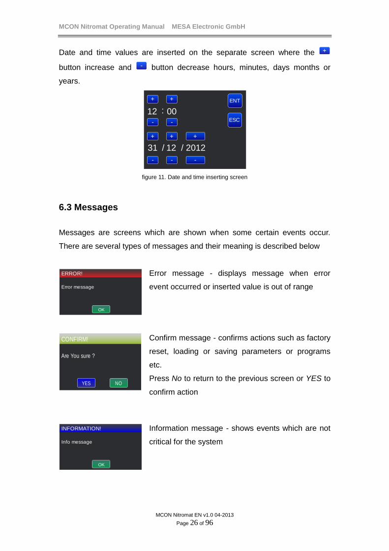
Date and time values are inserted on the separate screen where the +
button increase and - button decrease hours, minutes, days months or
years.
+ ENT
ESC-
12 00
201231 12 //
:
+
-
+ + +
- - -
figure 11. Date and time inserting screen
6.3 Messages
Messages are screens which are shown when some certain events occur.
There are several types of messages and their meaning is described below
OK
ERROR!
Error message
Error message - displays message when error
event occurred or inserted value is out of range
NO
CONFIRM!
Are You sure ?
YES
Confirm message - confirms actions such as factory
reset, loading or saving parameters or programs
etc.
Press No to return to the previous screen or YES to
confirm action
OK
INFORMATION!
Info message
Information message - shows events which are not
critical for the system

MCON Nitromat Operating Manual MESA Electronic GmbH
MCON Nitromat EN v1.0 04-2013
Page 27 of 96
OK
WARNING!
Warning message
Warning message - shows warning immediately
after warning condition is met. Warnings can be
visible in Warnings screen.
PROGRESS!
Progress message - shows the progress of the
actions which requires some finite time to be
finished
6.4 Main menu
Main menu is root of the menu structure where user can navigate to all
features and parameters. After device powering up, on the screen will be
displayed Normal View screen. Exit from Normal View screen will display
Main menu.
Main menu
Normal View Settings
Maintenance
Logging
Programs
Setpoints
figure 10. MCON Nitromat Main menu
To choose (enter) the menus from Main menu screen, just press desired
button or navigate focus with and keys and press to enter into
focused menu.
On the diagram below is shown menu structure of the MCON Nitromat. Exit
from one menu (or screen) returns the previous menu.

MCON Nitromat Operating Manual MESA Electronic GmbH
MCON Nitromat EN v1.0 04-2013
Page 28 of 96
figure 11. Menus structure
In the Normal View screen are displayed all measurements and control data
for the nitriding process.
Settings menu contains all configurations and parameters which are divided
into several submenus. See the “Settings” chapter for detailed description of
parameters and settings.
Temperature, Kn, N2 and CO2 control parameters are available from the
Control menu which is detailed described in the “Control” section.
In the Maintenance menu user can view in details informations about
measurements and inputs and outputs. Detailed description about this feature
can be found in the “Maintenance” section.
1: Normal View
2: Settings
2: System
4: Nitriding settings
3: Maintenance
5: Logging
6: Setpoints
1: Temperature control
2: Kn level control
4: Programs
1: Measurements
1: Setpoints
1: Control fsettings
3: Alarms
Main Menu
5: Analog inputs
7: Config tracks
2: I/O review
6: Comm. config
2:COM2
3:Ethernet
1:COM1
2:Digital outputs
3:Digital inputs
1:Terminals
5:Analog outputs
6:Test relays
4:Analog inputs
MCON Nitromat Operating Manual MESA Electronic GmbH
MCON Nitromat EN v1.0 04-2013
Page 29 of 96
Programs menu allows managing programs. This menu is also available from
the Setpoints screen. Programs menus and feature are described in the
“Programs” section.
Logging screen shows all informations and configurations for the logging
feature. Detailed description can be found in the “Logging” section.
6.5 Normal View
Normal View is accessible from the Main menu→Normal view.
Normal view screen shows all important measurement and control data. It
contains several pages which are listed by pressing navigation button .
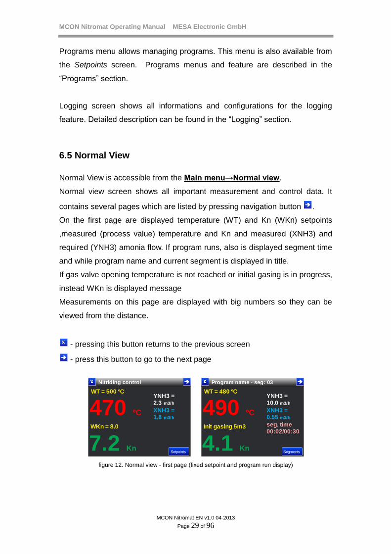
On the first page are displayed temperature (WT) and Kn (WKn) setpoints
,measured (process value) temperature and Kn and measured (XNH3) and
required (YNH3) amonia flow. If program runs, also is displayed segment time
and while program name and current segment is displayed in title.
If gas valve opening temperature is not reached or initial gasing is in progress,
instead WKn is displayed message
Measurements on this page are displayed with big numbers so they can be
viewed from the distance.
- pressing this button returns to the previous screen
- press this button to go to the next page
Nitriding control
WT = 500 ºC
WKn = 8.0
470 ºC
7.2 Kn
YNH3 = 2.3 m3/h
XNH3 = 1.8 m3/h
Setpoints
Program name - seg: 03
WT = 480 ºC
Init gasing 5m3
490 ºC
4.1 Kn
YNH3 = 10.0 m3/h
XNH3 = 0.55 m3/h
Segments
seg. time00:02/00:30
figure 12. Normal view - first page (fixed setpoint and program run display)
MCON Nitromat Operating Manual MESA Electronic GmbH
MCON Nitromat EN v1.0 04-2013
Page 30 of 96
On the Normal view screen user can insert setpoint values directly by
pressing screen on the place where the WT or WKn value is displayed. This
way user doesn’t need to go to the setpoints menu in order to change setpoint
value. This option is only available when no program or production run and
the current user privilege is greater or equal the required.
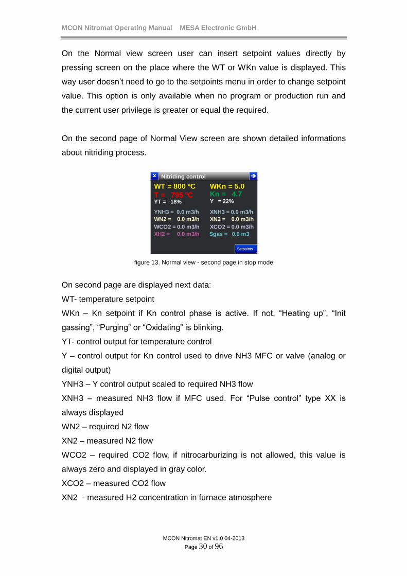
On the second page of Normal View screen are shown detailed informations
about nitriding process.
Nitriding control
WT = 800 ºC WKn = 5.0
T = 795 ºC Kn = 4.7 YT = 18% Y = 22%
Setpoints
YNH3 = 0.0 m3/h
WN2 = 0.0 m3/h
WCO2 = 0.0 m3/h
XH2 = 0.0 m3/h
XNH3 = 0.0 m3/h
XN2 = 0.0 m3/h
XCO2 = 0.0 m3/h
Sgas = 0.0 m3
figure 13. Normal view - second page in stop mode
On second page are displayed next data:
WT- temperature setpoint
WKn – Kn setpoint if Kn control phase is active. If not, “Heating up”, “Init
gassing”, “Purging” or “Oxidating” is blinking.
YT- control output for temperature control
Y – control output for Kn control used to drive NH3 MFC or valve (analog or
digital output)
YNH3 – Y control output scaled to required NH3 flow
XNH3 – measured NH3 flow if MFC used. For “Pulse control” type XX is
always displayed
WN2 – required N2 flow
XN2 – measured N2 flow
WCO2 – required CO2 flow, if nitrocarburizing is not allowed, this value is
always zero and displayed in gray color.
XCO2 – measured CO2 flow
XN2 - measured H2 concentration in furnace atmosphere

MCON Nitromat Operating Manual MESA Electronic GmbH
MCON Nitromat EN v1.0 04-2013
Page 31 of 96
Sgas – total amount of gas inserted into furnace from the beginning of the
process or time to end initial gassing (if no NH3 MFC presented when NH3
controll parameter is set to “Pulse control”). After initial gassing ends,
“finished” is shown.
Nitriding status – Actual state of process (Heating up, Initial gassing, Kn
control)
Setpoints button access menu with setpoints and programs to choose/edit. If
program runs, on this position is displayed Segments button which enters to
the screen with segments of program which runs.
Prog. 1 - seg:01
WT = 500 ºC Wkn = 0.0
T = 455 ºC Kn = 0.7 YT = 18% Y = 0.0%
Segments
YNH3 = 0.0 m3/hWN2 = 0.0 m3/h
WCO2 = 0.0 m3/h
XH2 = 0.0 m3/h
XNH3 = 0.0 m3/hXN2 = 0.0 m3/h
XCO2 = 0.0 m3/h
Sgas = 0.0 m3
tracks: A B C D E F G H I J K L M N O P
0 1 0 0 0 0 0 0 0 0 1 0 1 0 0 0
Prog. 1 - seg: 02
seg. time: 00:03/00:30 time : 00 24
figure 14. Normal view- third page (if program runs)
When program runs on the screen are shown program which is active, current
segment and segment elapsed/duration time and total time elapsed from
starting the program and track statuses. If heating, oxidating, purging or Initial
gasing is active, instead of WKn is shown phase which is active.
6.5.1 Bargraph display
To enter to bargraph screen, press button to switch to the next page from
the Normal View. Bargraph screen displays Kn level and temperature control
values in bargraph form.
Nitriding control
0 ºC
8.4
795 ºC
1800 ºC
0.00 50.00
SP
SP

MCON Nitromat Operating Manual MESA Electronic GmbH
MCON Nitromat EN v1.0 04-2013
Page 32 of 96
figure 15. Bargraph display
6.5.2 Graph display
Nitriding process can be shown in graph which displays a trend of changing
temperature and Kn level in time domain
Furnace control-Graph
200
300
400
500
600
700
800
900
1000
1100
0.0
5.0
10.0
15.0
20.0
25.0
30.0
35.0
40.0
45.0
WT = 500ºC Wkn = 5.0
T = 483 ºC Kn = 6.1
12:00:00 12:01:00
50.01200
Press to setmin and max
Press to setmin and max
Press to showbuttons
figure 16. Graph display
On the graph screen are plotted trend for Kn level and furnace temperature.
Graph feature has a history capability which allows viewing trend from the
starting of the control (transition from STOP to RUN mode).
On the graph screen is displayed trend in realtime. Additional trend options
and settings are available after pressing graph area when the button bar
appears below the graph. Tap on the screen several times to change buttons
which will be displayed or to hide button bar. When the button bar is
displayed, setpoints and current trend values are not displayed.
Pressing edges of screen, where are displayed temperature and Kn labels,
opens menu where can be set minimum and maximum for each trend display.
First group of buttons is for navigation through trend history. Press > or
< button to show trend data from one screen time backward or forward
respectively.
After pressing again graph area, another buttons appears. Press << button
to show trend data from the beginning of process or press >> button to show
realtime trend.
Next pressing on the graph area shows buttons for zoom in and zoom out
( Zoom+ and Zoom- Pressing these buttons will change screen time and redraw
trend points with longer or shorted screen time.

MCON Nitromat Operating Manual MESA Electronic GmbH
MCON Nitromat EN v1.0 04-2013
Page 33 of 96
Every graph sample point is stored to device internal memory. After switching
from STOP to RUN mode, device start to storing graph points to the internal
memory. Values are sampled on every sample time interval and trend is
showed within a selected screen time.
Sample time and screen time are parameters which are available after
pressing Settings button in the button bar bellow the graph.
Parameter: Graph sample time
Values : (2S, 5S, 10S, 20S)
Default: 2S
Description: Time interval on which one sample value (Kn level and
temperature) is stored to internal memory and plotted on the screen.
Parameter: Graph screen time
Values : (60S, 2min, 5min, 10min, 30min, 1h, 2h …)
Default: 60S
Description: Defines the duration of trend showed in one graph window.
Pressing Zoom+ / Zoom- buttons decrease/increase screen time respectively.
If screen time is 2h or greater, after pressing Zoom- screen time will be doubled
until whole trend can suit in one graph window.
6.6 System events
System events are errors, warnings and alarms. They occur under certain
circumstances and their status is displayed on the separate screen which is
accessible from the Normal View.
When event occurs in the Normal View screen is displayed flashing icon
which informs user that there is error, warning or alarm.
On the picture below are shown event icons from alarm, error and warning.

MCON Nitromat Operating Manual MESA Electronic GmbH
MCON Nitromat EN v1.0 04-2013
Page 34 of 96
Furnace control
Furnace control
Furnace control
Furnace control
figure 17. Event buttons showing
Detailed informations about occurred event are displayed by pressing event
icon or .
Errors
Amb. temp. error
AIN3 error
Invalid value
Overflow
Kn
Warnings
Gas release is blocked !
figure 18. Errors and warnings screens
Alarms
Furnace temp. Upper limit
Alarm1
Amb. temp. Upper limit
Alarm4
figure 19. Alarms screen
Errors, warnings and alarms are displayed on the same screen. Switching
from one to another is performed with button. If there are no any alarms,
errors or warnings, on the page for that type of event will be shown
information that there are no events occurred.
On the alarm page user can explicitly turn off alarm by pressing X button for
the certain alarm but only if alarm duration is zero (see Alarms section).

MCON Nitromat Operating Manual MESA Electronic GmbH
MCON Nitromat EN v1.0 04-2013
Page 35 of 96
6.6.1 Errors
Errors are critical event which occurs on some system failure invalid
measurement values or communication errors. On the errors screen are
displayed name of error and detailed description of error (optionally).
ERROR DESCRIPTION
EEPROM error Memory for storing parameters or calibration data
is corrupted.
Amb. temp. error Device ambient temperature cannot be measured
properly. Contact the supplier for details.
AIN error Analog input overflow or underflow.
Invalid value Kn cannot be measured and calculated correctly.
Modbus error Modbus communication has errors.
Ethernet error Ethernet communication cannot be established.
File system error USB or internal memory for storing log or graph
data cannot be initialized properly.
Time error Time and date is not set
6.6.2 Warnings
Warnings are less critical than errors and they don’t affect the device proper
functioning. On the next table are shown all warnings which can be occur in
the device.
WARNING DESCRIPTION
Device is in STOP mode Informs user that device is in STOP mode
Missing calibration! Analog input or analog output is not calibrated
which can decrease measurement accuracy.
Missing remote value! Remote setpoint is not received from the
MODBUS communication.
Gas release is blocked! Furnace temperature is below 500 ºC which
MCON Nitromat Operating Manual MESA Electronic GmbH
MCON Nitromat EN v1.0 04-2013
Page 36 of 96
forbid gas valve opening.
Stop from external! Program or control is stopped from digital input.
6.6.3 Alarms
On the alarm page are displayed activated alarms. For every activated alarm
is displayed detailed description what caused an alarm to be activated. For
details see the “Alarms” sections.
6.7. Setpoints
MCON Nitromat device has 2 control loops. First control loop is used to
control furnace temperature and second is for Kn control.
User can define loop set points in several ways:
- Fixed setpoints SP1 to SP4 are user explicitly defined setopoints
inserted via onscreen keyboard.
- Programs – defines temperature and Kn setpoints trend in time
(segments).
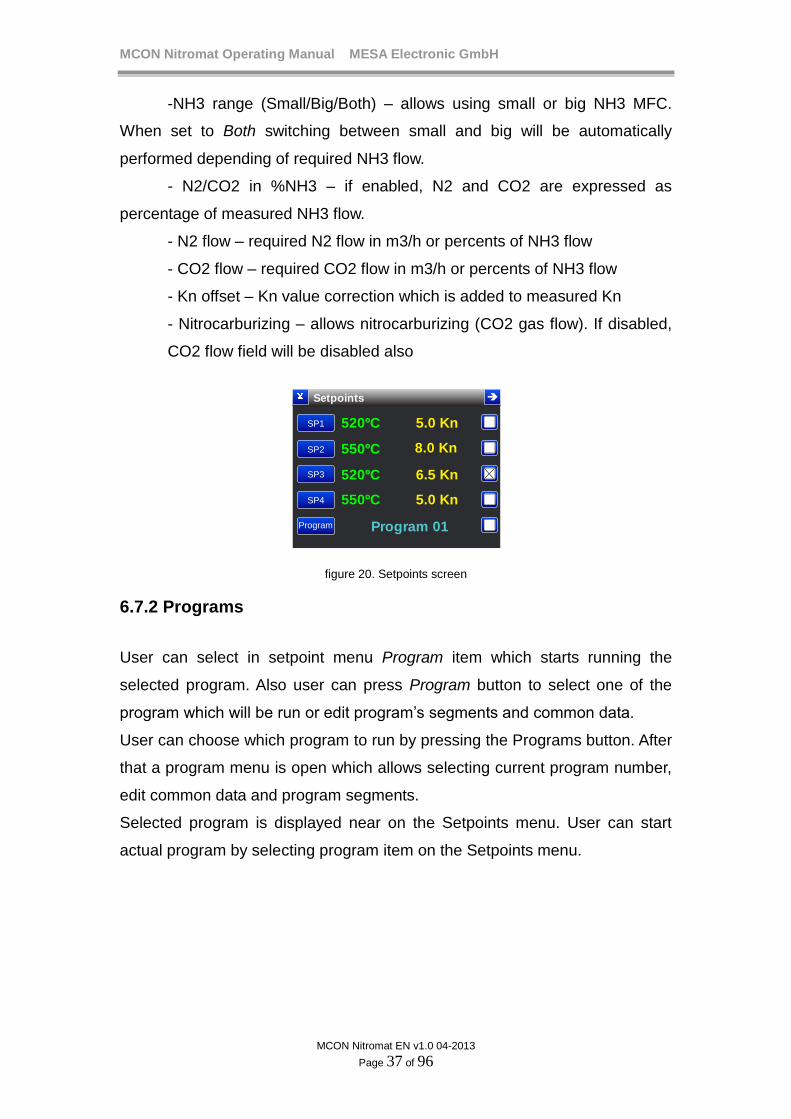
6.7.1 Fixed Setpoints
User can insert temperature and Kn level setpoint and their high and low
tolerances. When user select one of 4 fixed setpoints (in the setpoint menu),
controller starts the regulation with the setpoint values which are defined by
that setpoint.
There are 4 fixed setpoints which user can select. Every fixed setpoint has
next parameters:
-Temperature SP (from 200 to 1000 ºC)
-Kn SP (0 to 50)
- Temp SP+ and Temp SP- are upper and lower tolerances for
temperature
-Kn SP+ and Kn SP- are upper and lower tolerances for Kn.
MCON Nitromat Operating Manual MESA Electronic GmbH
MCON Nitromat EN v1.0 04-2013
Page 37 of 96
-NH3 range (Small/Big/Both) – allows using small or big NH3 MFC.
When set to Both switching between small and big will be automatically
performed depending of required NH3 flow.
- N2/CO2 in %NH3 – if enabled, N2 and CO2 are expressed as
percentage of measured NH3 flow.
- N2 flow – required N2 flow in m3/h or percents of NH3 flow
- CO2 flow – required CO2 flow in m3/h or percents of NH3 flow
- Kn offset – Kn value correction which is added to measured Kn
- Nitrocarburizing – allows nitrocarburizing (CO2 gas flow). If disabled,
CO2 flow field will be disabled also
Setpoints
SP1
SP2
SP3
SP4
Program
520ºC
550ºC
520ºC
550ºC
5.0 Kn
8.0 Kn
6.5 Kn
5.0 Kn
Program 01
figure 20. Setpoints screen
6.7.2 Programs
User can select in setpoint menu Program item which starts running the
selected program. Also user can press Program button to select one of the
program which will be run or edit program’s segments and common data.
User can choose which program to run by pressing the Programs button. After
that a program menu is open which allows selecting current program number,
edit common data and program segments.
Selected program is displayed near on the Setpoints menu. User can start
actual program by selecting program item on the Setpoints menu.

MCON Nitromat Operating Manual MESA Electronic GmbH
MCON Nitromat EN v1.0 04-2013
Page 38 of 96
7. Programs
Programs can be configured in Main menu→Programs or Main
menu→Normal view→Setpoints→Program menu.
Program is set of segments which are executed sequentially. Every segment
defines temperature and Kn setpoint and time required for those setpoints to
be approached. MCON Nitromat can store up to 99 programs. Every program
can be custom named and has its own number (from 1 to 99).
Every segment can activate some digital outputs when the segment is about
to run. This feature is called “program tracking”. There are 16 tracks, named
from A to P. Every track is associated with a digital output which it activates.
User can define tracks which will be activated or deactivated for every
segment.
100
200
0
300
400
500
600
700
800
900
1000
0.5
1.0
0
1.5
2.0
2.5
3.0
3.5
4.0
4.5
5.0
1 2 53 4 6 7
T (ºC) Kn
Furnace temperature
Kn
8
segment 1 2 3 4 5 6 7 8
Temperature
setpoint 400 ºC 450 ºC 500 ºC 570 ºC 600 ºC 600 ºC 480 ºC 0
Kn 0 0 0 1.5 1.5 2.0 5.0 0
segment
duration
30 min 45 min 10 min 50 min 8 min 25 min 50 min 20 min
figure 21.Example of program segments
Segment setpoint is target value which must be achieved on the end of
segment. If segment duration is short, then device tries to achieve setpoint as

MCON Nitromat Operating Manual MESA Electronic GmbH
MCON Nitromat EN v1.0 04-2013
Page 39 of 96
quick as possible. If segment time is too long, device will goes smoothly to the
target setpoint. Therefore there is no need to define rising times because it is
automatically calculated depending of the previous and current segment
setpoint value and the segment time.
For example: segment 3 has temperature setpoint SPT = 500 ºC, previous
segment 2 ends on 400 ºC,
Because segment time is 10 minutes, device will regulate temperature from
400 ºC to 500 ºC with raising value: (500 ºC - 400 ºC)/10min = 10 ºC/min. It is
assumed that the 500 ºC temperature will be reached at the end of segment.
When there is no need to have constant process value over the certain time, it
is required to define segment which has the same setpoint as previous
segment (dwell).
Every segment defines both temperature and Kn setpoints while N2 and CO2
flows are constant during whole program except CO2 which is active only on
certain segmens. To allow CO2 flow, nitrocarburizing must be enabled and
segment with appropriate track set must run. Nitrocarburizing track can be
configured in Nitromat settings.
Also segment can be defined as oxidating or purging.
Program parameters:
Parameter: Program no
Values: (1 - 99)
Default: 1
Description: Select number of program which has to be edited or started. User
must first choose program number before editing/viewing program parameters
or segments.
Parameter: Program name
Values: (text up to 15 characters)
Default: not set
Description: Program name for which describes program purpose.

MCON Nitromat Operating Manual MESA Electronic GmbH
MCON Nitromat EN v1.0 04-2013
Page 40 of 96
Parameters: Temp SP+/Temp SP-/Kn SP+/Kn SP- are the same as
parameters for the setpoints. Refer to the “Setpoints chapter”
Setpoints tolerances for the program execution are used only to define when
the control is achieved setpoint value in order to go to the next segment (only
if the X bit is set). These parameters are parts of a program.
Parameter: HN3 range
Values : (Small, Big, Both)
Default: Small
Description: Type of NH3 mass flow controller to be used for that program.
Parameter: N2/CO2 in %NH3
Values: (NO, YES)
Default: NO
Description: Determines if N2 and CO2 flow will be defined as percents of
NH3 flow. For example If this parameter set to YES and N2 is 10% and CO2
is 5%, when XNH3 is 10 m3/h, N2 flow will be 1 m3/h and CO2 0.5 m3/h.
Parameter: N2 flow
Values: (0 – 100 m3/h or 0-50%)
Default: 0 m3/h
Description: N2 gas flow setpoint
Parameter: CO2 flow
Values: (0 – 130 m3/h or 0-50%)
Default: 0 m3/h
Description: CO2 gas flow setpoint
Parameter: Kn offset
Values: (-9.9 , 9.9)
Default: 0
Description: Correction of Kn
Parameter: Nitrocarburizing

MCON Nitromat Operating Manual MESA Electronic GmbH
MCON Nitromat EN v1.0 04-2013
Page 41 of 96
Values: (NO, YES)
Default: NO
Description: Allows CO2 flow. When NO, CO2 flow is zero and when YES
CO2 flow is controlled according to the CO2 flow parameter but only in
segments with appropriate track set.
7.1 Tracks config
Every track can be set to activate desired digital output. Tracks configuration
is available on: Main menu→Programs→Config tracks menu or from Main
menu→Settings→Config tracks menu.
Parameter : Track A, Track B, Track C … Track P
Values: (not set, dout 1, dout 2, dout 3 … dout n)
Default: not set
Description: Digital output which is associated to track. If not set, track will not
activate any digital output. Tracks configuration is common for all programs.

MCON Nitromat Operating Manual MESA Electronic GmbH
MCON Nitromat EN v1.0 04-2013
Page 42 of 96
7.2 Program segments
Program segments can be edited under segments screen which is available
in: Main menu→Programs→Segments screen. Before editing or viewing
segments, user must choose desired program.
Program 1 seg. 1-6
1
2
3
4
5
6
duration T Kn/tech X bit
00:30
00:45
00:10
00:50
00:08
00:25
400ºC
450ºC
500ºC
570ºC
600ºC
600ºC
0.0
Oxidating
Purging
1.5
1.5
2.0
0
0
0
0
0
0
Program 1 seg. 7- 12
7
8
9
10
11
12
duration T Kn/tech X bit
00:50
00:20
00:00
00:00
00:00
00:00
480ºC
0ºC
0ºC
0ºC
0ºC
0ºC
5.0
Purging
0.0
0.0
0.0
0.0
0
0
0
0
0
0
figure 22. Program segments displaying
Segments screen shows 6 segments by one screen. Press button to show
next 6 segments or button to show previous 6 segments. On the first page
there are basic data for every segment: time of segment (duration),
temperature setpoint (T), Kn value and X bit. To change segment values,
press appropriate segment button which opens segment editing menu. If
segment is purging or oxidating type, instead Kn value (which is zero in these
cases) is displayed “Oxidating” or “Purging”. For nitrocarburizing segments,
besides Kn value is displayed “CO2” (for ex. “4.2 + CO2”).
In the Edit segment menu there are temperature and Kn setpoint parameters
which have the same meaning and values range as fixed setpoints in Setpoint
menu.

MCON Nitromat Operating Manual MESA Electronic GmbH
MCON Nitromat EN v1.0 04-2013
Page 43 of 96
If segment technology is “Kn control”, Kn setpoint can be >0 only if segment
temperature is set to be higher than gas release temperature. First segment
which have Kn>0 is used for initial gasing which means that Kn regulation for
this segment will not start before initial gas volume enters into the furnace.
First segment of every program has Kn setpoint set to zero regardless of
segment tech.
Segment parameters are:
Parameter : Segment time
Values: (0 – 199 min)
Default: 30 min
Description: Segment time in minutes.
Parameter: X bit
Values: (checked, unchecked)
Default: unchecked
Description: When the X bit is checked (value “1”), this segment waits to
reach process values according to setpoints and their tolerances before
switching to the next step even the segment time elapses.
Parameter: Technology
Values: (Kn control, Nitrocarburizing, Oxidating, Purging)
Default: Kn control
Description: Defines step technology and automatically sets appropriate track.
Purging and Oxidating tracks automatically sets WKn to zero (not NH3
allowed). For details about technologies see chapter 12. Nitriding.
TIP
When You need to reach setpoint as fastest as possible,
You need to declare segment to be very short (1 minute)
and set X bit to 1. This way, device will not smoothly
change setpoint value because time is very short and do
MCON Nitromat Operating Manual MESA Electronic GmbH
MCON Nitromat EN v1.0 04-2013
Page 44 of 96
not go to the next segment until current segment setpoint
regulated.
7.2.1 Set segment tracks
To set/unset segment tracks press the tracks button in Edit segment menu.
On the segment tracks screen there are tracks A to P which can be
configured. If certain track is set (checked) its digital output will be activated
when that segment executes, otherwise if track is unchecked, appropriate
digital output will be deactivated on this segment. Technology tracks are
disabled for setting directly. Instead, they are set when appropriate technology
for segment is configured.
TIP
Use tracks to send commands to PLC or some other
electronics which can be used for automation control of
the furnace. For ex. some tracks can be activated on the
end of a programm in order to close furnace door or insert
some aditional gases.
To run the desired program go to the Normal view and on the second page
press Setpoints button. In the Setpoints screen check the Program option.
This will immediately start the first segment of a selected program and switch
the device to RUN mode.
NOTE
Some tracks are reserved for nitrocarburizing,
oxidating and purging. Go to Settings→Nitriding Settings
menu to define tracks for technologies.

MCON Nitromat Operating Manual MESA Electronic GmbH
MCON Nitromat EN v1.0 04-2013
Page 45 of 96
8. Control
Menu path: Main Menu→ Settings→System menu→Control.
In Control menu, user can configure parameters for temperature, Kn, N2 and
CO2 flow control.
8.1 Furnace temperature control
Temperature control parameters:
Parameter : Control preset
Values : (OFF, PID preset1, PID preset2, PID preset3)
Default : PID preset1
Description: Parameters for every loop are organized into 3 presets. Every
preset contains all control parameters that will be used if this preset is chosen
in the Control preset parameter. To deactivate control loop, chose OFF option.
Changing the PID preset parameters can be performed in:
Main Menu→ Settings→System menu→Control→Temperature
control→PID preset n
Parameter : Control type
Values: (PID, On/Off)
Default: PID
Description: Defines which type of control will be used when this preset is
active.
Parameter: Control output
Values: (Heating, Heating/Cooling)
Default: Heating
Description: Heating – 2 state control output (Heating on/off)
Heating/Cooling – 3 state output (heating, cooling and off)
Parameter: Deadband
Values: (0-40 ºC)

MCON Nitromat Operating Manual MESA Electronic GmbH
MCON Nitromat EN v1.0 04-2013
Page 46 of 96
Default: 5 ºC
Description: For the the 3 state output type and PID control type, defines
minimum process temperature which must be above SP to allow cooling
activator activation.
Parameter: Derivative type
Values: (Error, PV)
Default: Error
Description: When set to Error, differential term error is calculated as
difference of current and error in previous scan cycle. When set to PV,
differential term error is calculated as difference of the process values in
current and last cycle.
Parameter: Upper hysteresis
Values: (0 – 100 ºC)
Default: 10 ºC
Description: Effective only for On/Off control type. For 2 state output, heating
is turned off and for 3 state output type, cooling is turned on when the PV
becomes greater then SP+Upper hysteresis.
Parameter: Lower hysteresis
Values: (0 – 100 ºC)
Default: 10 ºC
Description: Effective only for On/Off control type. Heating is turned on when
the PV becomes lower than SP-Lower hysteresis
NOTE
Cooling PID parameters are only available if the control
output type is set to Heating/Cooling
Heating and cooling PID parameters:
Parameter: PB heating, PB cooling
Values: (0 – 9999.0 %/ºC)
MCON Nitromat Operating Manual MESA Electronic GmbH
MCON Nitromat EN v1.0 04-2013
Page 47 of 96
Default: 60 %/ ºC
Description: Proportional band parameter of a PID control. Smaller values
decrease system response and error amplification.
Parameter: Ti heating, Ti cooling
Values: (0 – 9999.0 % / (ºC*min ) )
Default: 10% / (ºC*min )
Description: Integration time of error. Bigger values increase system
response to error duration over time. When set to 0, integration part of a PID
algorithm is disabled.
For example: If Ti = 10%/(ºC*min ) this will produce 10% correction value (Y)
when error is 1 ºC constant in period of 1 minute. After 2 minutes it will be
20% etc.
Parameter: Td heating, Td cooling
Values: (0 – 9999.0 %/(ºC/min ))
Default: 5 %/(ºC/min ))
Description: Derivative constant of PID control algorithm. Greater value
increase system responses to process value changing in short time. When set
to 0, derivative part of a PID algorithm is disabled.
For example: If Td = 5%/(ºC/min ) this will produce 5% correction value (Y)
when error change rate is 1ºC/min. If error change rate is 2ºC/min, derivative
term will be 10%
Parameter: Cycle time heating, Cycle time cooling
Values: (0 – 1200 S)
Default: 20 S
Description: Actuators are activated when cycle time elapses. When Y =
100%, actuator will be turned on whole cycle. If the Y = 50%, actuator will be
on half cycle time. For more details view control principle chapter.
Parameter: Min. ON time heating, Min. ON time cooling
Values: (0 – 60 S)
Default: 1 S

MCON Nitromat Operating Manual MESA Electronic GmbH
MCON Nitromat EN v1.0 04-2013
Page 48 of 96
Description: Minimum allowed time for actuator to be activated. It prevents
turning on activators if for the small Y values and cycle times.
Parameter: Cooling factor
Values: (0 – 2.00)
Default: 1.00
Description: This parameter is available only if Heating/Cooling output is set
and the PID control type. Because heating and cooling PID parameters are
separated it is possible to use heating parameters for cooling too depending
of cooling factor value. If cooling factor is 0, cooling phase will be processed
with dedicated cooling PID parameters, If cooling factor is not equal 0, cooling
PID parameters will be the same as heating parameters except PB which will
be multiplied with the cooling factor. Therefore cooling factor determines
difference between the response of a system in cooling and heating phases.
Parameter: Control out1, Control out 2
Values: (not set, dout 1, dout 2, dout 3 … dout n)
Default: not set
Description: When not set, control output for heating, cooling, gas, air or
motorized valve will not be activated even the Y value will be affect during
control. Contol 1 output determines digital output for heating (temperature
control) or for gas or valve opening (for Kn control). Control 2 output
determines digital output for cooling (temperature control only). For details
about digital outputs assigning view the chapter Digital outputs assignment.
NOTE
If the control output is set to 2 state or analog, Control 2
output will be automatically not set (released for other
purposes). If control type is disabled both control outputs
will be not set.
MCON Nitromat Operating Manual MESA Electronic GmbH
MCON Nitromat EN v1.0 04-2013
Page 49 of 96
8.2 Kn control
Parameters Control preset and Derivative type have the same meaning as for
the Temperature control. PID parameters are detailed described in section 20.
“Control principle”.
Parameter: NH3 control
Values: (MFC controller, Pulse control)
Default: MFC controller
Description: MFC controller – Kn correction value (Y) will be presented on
AOUT1 in order to drive NH3 MFC.
Pulse control – desired digital output will be used for control when
no MFC controller is available. Cycle time parameter determines valve on
time when Y = 100%.
Parameter: PB
Values: (0 – 9999.0 %/ Kn)
Default: 60 %/ Kn
Description: Proportional band parameter of a PID control.
Parameter: Ti
Values: (0 – 9999.0 %/(Kn*min ) )
Default: 10%/(Kn*min )
Description: Integration time of error.
Parameter: Td
Values: (0 – 9999.0 %/(Kn/min ))
Default: 5 %/(Kn/min ))
Description: Derivative time of PID control algorithm.
Parameter: Cycle time
Values: (0 – 1200 S)
Default: 20 S
MCON Nitromat Operating Manual MESA Electronic GmbH
MCON Nitromat EN v1.0 04-2013
Page 50 of 96
Description: Same as for temperature control. Used only if NH3 control
parameter is set to “Pulse control”.
Parameter: Min. ON time
Values: (0 – 60 S)
Default: 1 S
Description: Same as for temperature control. Used only if NH3 control
parameter is set to “Pulse control”.

MCON Nitromat Operating Manual MESA Electronic GmbH
MCON Nitromat EN v1.0 04-2013
Page 51 of 96
9. Alarms
MCON Nitromat provides 4 analog alarms and one digital alarm. They can be
configured into Main Menu→ Settings→Alarms menu. There are 4 analog
alarms and one digital alarm.
9.1 Analog alarms
Analog alarms are used to check analog values such as measurement results
and to generate alarm (trigger appropriate digital output) if the value of
monitored measurement value is not valid according to the alarm constraints.
figure 23. Alarm configurations
Analog alarm has 2 sources of measurements which can be monitored. If the
source is AIN (analog input) it can be raw value (voltage or current) or scaled
value (depends of AIN configuration). For AIN source, user must insert which
analog input is attached to alarm source.
Alarm source 2 is optional and it allows that one alarm can be associated by 2
measurements in several combinations. It is possible to trigger alarm if both

MCON Nitromat Operating Manual MESA Electronic GmbH
MCON Nitromat EN v1.0 04-2013
Page 52 of 96
alarm sources are activated (AND), only one of sources are active (XOR) or
any of them (OR).
Value of an alarm source (temperature, Kn level or analog input value) is
compared to the lower and upper limits. Alarm is generated if value is outside
area which is defined by upper and low limits. Alarm is deactivated when
value is inside area which is defined by limits and appropriate hysteresis.
Source value
Upper limit
Lower limit
Upper hysteresisUpper limit
Lower hysteresis
Alarm status
change time
change rate
figure 24. Alarm activating conditions
Alarm source value also can be monitored by its change rate. When value
changes faster than allowed in user defined time interval, it will be triggered.
Thus change rate is value of difference in change time interval.
For example: Change rate = 20ºC and Change time is 10S. Alarm will be
activated when temperature changes above 20ºC in 10 seconds therefore
effective change rate is: 2ºC/S
Analog alarm parameters:
Parameter: Alarm source
Values: (OFF, AIN, Amb. temp, Furnace temp., H2 level, Kn value)
Default: OFF
Description: Value which will be monitored by the alarm.
Parameter: AIN
Values: (AIN1, AIN2, AIN3, AIN4, AIN5)
MCON Nitromat Operating Manual MESA Electronic GmbH
MCON Nitromat EN v1.0 04-2013
Page 53 of 96
Default: AIN1
Description: When alarm source is AIN, this parameter defines which analog
input is used for alarm source.
Parameter: Ain value
Values: (Raw value, Scaled value)
Default: Scaled value
Description: Raw value - analog input voltage or current value is monitored
by alarm
Scaled value - analog input scaled value (measurement) is
monitored by alarm.
Parameter: Upper limit
Values: (0- 9999.99)
Default: 0
Description: When value is above upper limit, alarm is triggered.
Parameter: Lower limit
Values: (0- 9999.99)
Default: 0
Description: When value is below lower limit, alarm is triggered.
Parameter: Upper hyst.
Values: (0- 9999.99)
Default: 0
Description: When value is below Upper limit - Upper hyst, alarm is
deactivated.
Parameter: Lower hyst.
Values: (0- 9999.99)
Default: 0
Description: When value is above Lower limit +Lower hyst, alarm is
deactivated.

MCON Nitromat Operating Manual MESA Electronic GmbH
MCON Nitromat EN v1.0 04-2013
Page 54 of 96
Parameter: Change rate
Values: (0- 9999.99)
Default: 0
Description: Maximum allowed difference of value in time period of Change
time.
Parameter: Change time
Values: (0- 9999.99)
Default: 0
Description: time quantum in which change rate is monitored.
Parameter: Alarm logic
Values: (OR,AND,XOR)
Default: OR
Description: Logic function performed on both alarm sources. If only one
alarm source is enabled (Alarm source parameter is not equal OFF), this
parameter will be disabled.
Parameter: Delay
Values: (0- 9999S)
Default: 5S
Description: Time after alarm activating which must elapses before triggering
digital output of alarm.
Parameter: Duration
Values: (0- 9999S)
Default: 5S
Description: Duration of alarm active state. If this value is 0 S, alarm will be
active until user stop the alarm by pressing button in the alarms
information screen. If value is not 0 S, alarm will be turned off after duration
period but it will be turned on again if alarm condition still exists.
Parameter: Inverting
Values: (NO, YES)
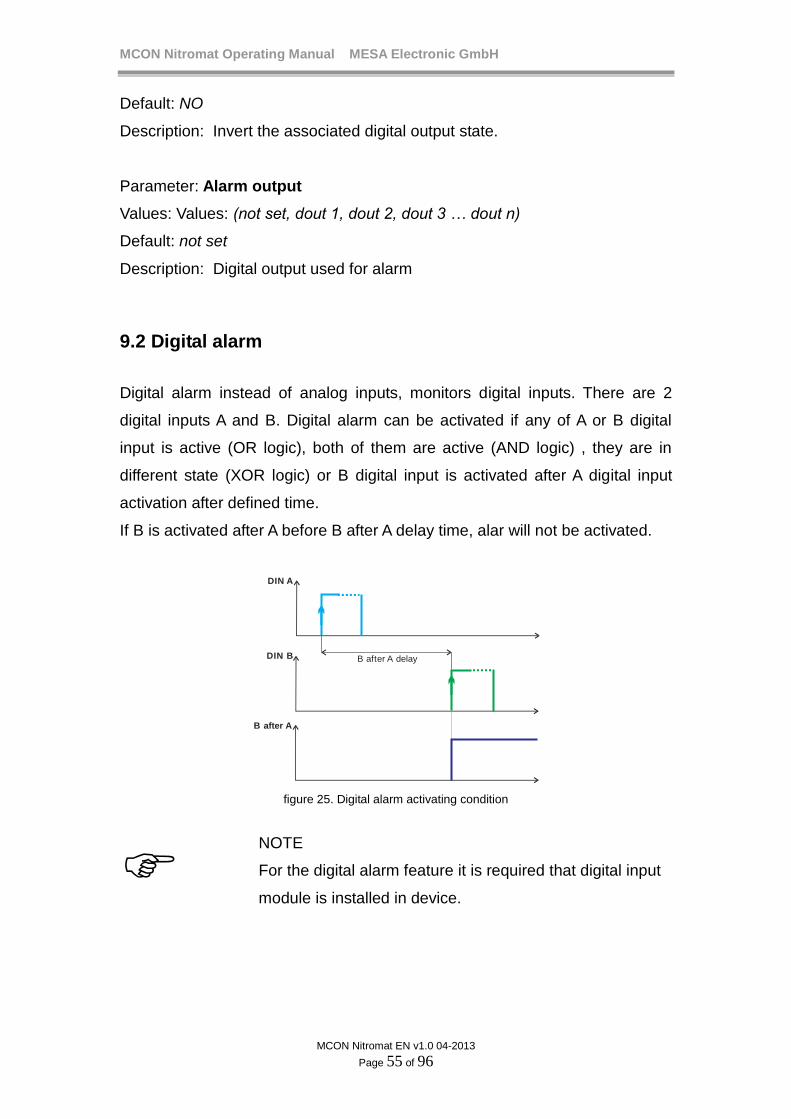
MCON Nitromat Operating Manual MESA Electronic GmbH
MCON Nitromat EN v1.0 04-2013
Page 55 of 96
Default: NO
Description: Invert the associated digital output state.
Parameter: Alarm output
Values: Values: (not set, dout 1, dout 2, dout 3 … dout n)
Default: not set
Description: Digital output used for alarm
9.2 Digital alarm
Digital alarm instead of analog inputs, monitors digital inputs. There are 2
digital inputs A and B. Digital alarm can be activated if any of A or B digital
input is active (OR logic), both of them are active (AND logic) , they are in
different state (XOR logic) or B digital input is activated after A digital input
activation after defined time.
If B is activated after A before B after A delay time, alar will not be activated.
DIN A
DIN B
B after A
B after A delay
figure 25. Digital alarm activating condition
NOTE
For the digital alarm feature it is required that digital input
module is installed in device.
MCON Nitromat Operating Manual MESA Electronic GmbH
MCON Nitromat EN v1.0 04-2013
Page 56 of 96
Digital alarm parameters:
Parameter: Alarm logic
Values: Values: (Disabled, A and B, A or B, A xor B, B after A)
Default: Disabled
Description: If Disabled, digital alarm will not be monitored
Parameter: Dig. in A, Dig. in B
Values: Values: (din1, din2, din3, din4)
Default: din1
Description: Digital input for digital input alarm.
Parameters: B after A delay, Delay, Duration, Inverting and Alarm output are
the same as in analog alarms!

MCON Nitromat Operating Manual MESA Electronic GmbH
MCON Nitromat EN v1.0 04-2013
Page 57 of 96
10. Maintenance
Maintenance is feature for monitoring system measurements and inputs and
outputs.
10.1 Measurements
Measurements screen is presented on Main
Menu→Maintenance→Measurements.
Measurements screen shows measurement values on the presented analog
inputs. On the each page of the Measurements screen are displayed
measurements for one analog input.
AIN 1
Correction Clear corr.
min: 0.29 mV
265 ºC
0.336 mVmin: 13.82 mV
Furn. temp.
37.62 ºC
figure 26. Measurements screen for AIN1
NOTE
Correction feature is only available if logged user has
enough privileges.
Press button to switch to the next analog input.
To correct current measurement value, press Correction
button and enter correct
value. Therefore a correction point will be formed and further measurements
will be corrected using this correction point.
When entering correction value, as a default value is offered uncorrected
value.

MCON Nitromat Operating Manual MESA Electronic GmbH
MCON Nitromat EN v1.0 04-2013
Page 58 of 96
To clear correction, press Clear corr.
button which is shown only if there are
existing corrections of measured value.
10.2 I/O overview
I/O review is used to show all analog and digital inputs and outputs in the
device which are installed. I/O screens are available in the Main
Menu→Settings→I/O Review menu.
10.2.1 Terminals
Terminals screen shows all the connections from the back side of the device.
There are 4 rows of terminals. Pressing the screen area on the each row
shows the screen with terminals description for that row of terminal.
Terminals
45 46 47 48 49 50 51 52 53 54 55 56 57 58 59 60
29 30 31 32 33 34 35 36 37 38 39 40 41 42 43 44
1 2 3 4 5 6 7 8 9 10 11 12 13 14 15 16
17 18 19 20 21 22 23 24 25 26 27 28
Terminals
1.
2.
3.
4.
5.
6.
7.
8.
9.
10.
11.
12.
13.
14.
15.
16.
L
N
DOUT2 (NO)
DOUT2 (COM)
DOUT2 (NC)
DOUT1 (NO)
DOUT1 ( )COM
DOUT1 (NC)
RXA
RXB
TXB / RS485 B
TXA / RS485 A
GND_ISO
A
B
GND
figure 27. Terminals screen
10.2.2 Digital outputs
This screen shows all digital outputs which are installed in the device and their
assigned function. Details are described in the 12.4 Digital outputs
assignment chapter.

MCON Nitromat Operating Manual MESA Electronic GmbH
MCON Nitromat EN v1.0 04-2013
Page 59 of 96
Digital outputs
Furnace Heating
DOUT1
Big NH3 MFC
DOUT2
DOUT3
DOUT4
Alarm1
DOUT5
DOUT6
TrackA TrackBDOUT7
TrackC TrackDDOUT8
figure 28. Digital outputs assignments and status
Digital outputs can be used for more than one function so they are all
displayed (for ex. Track A and Track B on DOUT7). If a digital output is
unassigned, there is no function shown on the right side (for ex. DOUT6).
When the digital output is active, it is colored with red (DOUT2, DOUT7).
Inactive digital outputs are white.
10.2.3 Digital inputs
Digital inputs screen shows all digital inputs statuses and meanings. Active
digital inputs (those with high input state) are colored red.
Active DIN1 input pauses program running (if program setpoint is selected) or
turn off control outputs (if one of fixed, remote or external setpoints is chosed).
When DIN2 is active more than 10 seconds, program goes to the next
segment. If this digital input is active more than 90 seconds, current running
program will be restarted. This digital input has no effect when no program or
production is running.
Active DIN3 switchs user level to the lowest priority (LEVEL 0) and thus forbid
access to major system functions, setpoints and parameters (See User
privileges chapter).
DIN4 can be used for Dig In alarm feature.

MCON Nitromat Operating Manual MESA Electronic GmbH
MCON Nitromat EN v1.0 04-2013
Page 60 of 96
Digital outputs
Control Off / Program pauseDIN1
Program next / Program resetDIN2
Block inputDIN3
Not usedDIN4
figure 29. Digital inputs functions and status
10.2.4 Analog inputs
On the analog inputs screen are shown all installed analog inputs ant their
functionalities.
Analog inputs
AIN1 - Thermocouple B - Furnace tempCalib. date: 01/08/2013
AIN2 - 40-20 mA Rext - H2 SensorCalib. date: 01/08/2013
AIN3 - 40-20 mA Rext - MFC N2Calib. date: 01/08/2013
AIN4 - 40-20 mA - MFC NH3Calib. date: 01/08/2013
AIN5 - 40-20 mA - MFC CO2Calib. date: 01/08/2013
figure 30. Analog inputs screen
10.2.5 Analog outputs
Analog outputs screen shows all analog outputs which are installed in the
device. For every analog output are displayed function and calibration info as
well as current value in milliamps.
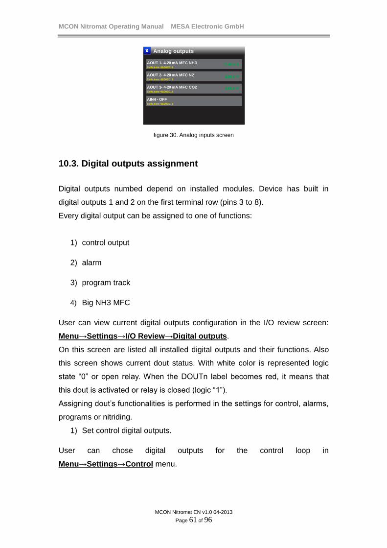
MCON Nitromat Operating Manual MESA Electronic GmbH
MCON Nitromat EN v1.0 04-2013
Page 61 of 96
Analog outputs
AOUT 1- 4-20 mA MFC NH3Calib. date: 01/08/2013
AOUT 2- 4-20 mA MFC N2Calib. date: 01/08/2013
AOUT 3- 4-20 mA MFC CO2Calib. date: 01/08/2013
AIN4 - OFFCalib. date: 01/08/2013
12.45 mA
6.20 mA
4.00 mA
figure 30. Analog inputs screen
10.3. Digital outputs assignment
Digital outputs numbed depend on installed modules. Device has built in
digital outputs 1 and 2 on the first terminal row (pins 3 to 8).
Every digital output can be assigned to one of functions:
1) control output
2) alarm
3) program track
4) Big NH3 MFC
User can view current digital outputs configuration in the I/O review screen:
Menu→Settings→I/O Review→Digital outputs.
On this screen are listed all installed digital outputs and their functions. Also
this screen shows current dout status. With white color is represented logic
state “0” or open relay. When the DOUTn label becomes red, it means that
this dout is activated or relay is closed (logic “1”).
Assigning dout’s functionalities is performed in the settings for control, alarms,
programs or nitriding.
1) Set control digital outputs.
User can chose digital outputs for the control loop in
Menu→Settings→Control menu.

MCON Nitromat Operating Manual MESA Electronic GmbH
MCON Nitromat EN v1.0 04-2013
Page 62 of 96
For the Temperature control those outputs are for heating and for cooling and
for Kn control outputs are for valve pulse width control (if NH3 control
parameter are set to “Pulse control”).
In all loops there are Control 1 and Control 2 items where user can chose
which digital output will be used for this control output.
If the current PID preset is disabled, both Control outputs are disabled too and
their values automatically set to not set value. If current PID preset is
configured to have 2 state output (heating only, or 2 state output), user can
only choose Control out1. Control out2 is enabled only for 3 state outputs in
temperature control (heating/cooling). Also if the current PID preset is set to
produce analog output both control outputs are disabled.
2) Set alarm dout
User can chose digital outputs for the control loop in
Menu→Settings→Alarms menu
In alarm menu user can chose alarm output as one of offered digital
outputs.
If alarm is disabled, alarms output is disabled too and automatically set
to not set value
3) Program tracks
Control tracks can be customized in Menu→Programs→Config tracks
menu.
There are 16 items, one for every track (A to P). User can chose digital output
for every track or can set it to not_set value. If track output is not_set it not
trigger any of digital outputs but remote devices can accept track status via
communication.
4) Big NH3 MFC
Big NH3 MFC digital output can be configured in Menu→Settings→Nitriding
settings .
10.3.1 Digital output assignment constraints

MCON Nitromat Operating Manual MESA Electronic GmbH
MCON Nitromat EN v1.0 04-2013
Page 63 of 96
When user select digital output for some functionality, there will be shown
(enabled) only those digital outputs which are not already used by some other
function. There are some rules which are automatically performed when
selecting digital outputs and which disables used dout’s.
Digital output for control cannot be used for any other function, thus it
will be disabled when selecting in other functions.
Digital output for alarms cannot be used for any other function, thus it
will be disabled when selecting in other functions.
Digital output for tracks can duplicated. For ex. track_a and track_e can
be both on dout_5, or track_b and big NH3 MFC out can be both on
dout_7. According to previous rules, track digital outputs cannot be the
same digital outputs used for control or alarm.
Big NH3 MFC output can be the same as track output but not the same
as control or alarm output.

MCON Nitromat Operating Manual MESA Electronic GmbH
MCON Nitromat EN v1.0 04-2013
Page 64 of 96
11. Analog inputs
Analog inputs can be configured in Main Menu→Settings→Analog inputs
menu.
11.1 Analog input 1
Analog input 1 (AIN1) is for the furnace temperature measurement. Therefore,
only parameter which can be configured for AIN1 is Thermocouple type.
11.2 Analog input 2
Analog input 2 (AIN2) is for connecting H2 sensor (Kn level measurement).
AIN2 is 4-20 mA input. Parameters for AIN2 are scaling in %H2 for H2 sensor.
11.3 Analog input 3
Analog input 3 (AIN3) is for connecting output from N2 MFC (N2 flow
measurement). AIN3 is 4-20 mA input. Parameters for AIN3 are scaling in
m3/h for N2 flow.
11.4 Analog input 4
Analog input 4 (AIN4) is for connecting output from both NH3 mass flow
controllers (big and/or small one). AIN4 is 4-20 mA input. Parameters for AIN4
are scaling in m3/h for NH3 flow for both small and big NH3 MFC.
11.5 Analog input 5
Analog input 5 (AIN5) is for connecting output from CO2 MFC (CO2 flow
measurement). AIN5 is 4-20 mA input. Parameters for AIN5 are scaling in
m3/h for CO2 flow.

MCON Nitromat Operating Manual MESA Electronic GmbH
MCON Nitromat EN v1.0 04-2013
Page 65 of 96
11.6 Analog inputs parameters
Analog inputs parameters for AIN1 only:
Parameter: Thermocouple
Values: Values: (B,C,E,J,K,L,M,N,R,S,T)
Default: B
Description: Type of thermocouple. Available only if input type is set to
Thermocouple.
Analog inputs parameters for AIN4 only
Parameter: NH3 small start
Values: Values: (0-9.0 m3/h)
Default: 0 m3/h
Description: NH3 flow which will be measured on 4 mA with small MFC.
Parameter: NH3 small end
Values: Values: (1-10.0 m3/h)
Default: 10 m3/h
Description: NH3 flow which will be measured on 20 mA with small MFC.
Parameter: NH3 big start
Values: Values: (0-90.0 m3/h)
Default: 0
Description: NH3 flow which will be measured on 4 mA with big MFC.
Parameter: NH3 big end
Values: Values: (10-100.0 m3/h)
Default: 100 m3/h
Description: NH3 flow which will be measured on 20 mA with big MFC.

MCON Nitromat Operating Manual MESA Electronic GmbH
MCON Nitromat EN v1.0 04-2013
Page 66 of 96
12. Nitriding Nitriding and Nitrocarburizing process control contains next phases:
Heating up – reaching gas release temperature before inserting gas into furnace.
Oxidating – temperature control with air insertion with the program track
Purging – purging track is activated which opens purging gas valve (usually N2 gas)
Kn control – inserting ammonia and N2 to achieve desired Kn
Nitrocarburizing – Kn control with CO2 flow enabled and nitrocarburizing track activated
On the next table are shown nitriding phases and conditions in which every phase can be executed when program control is active:
Nitriding phase Condition NH3 flow N2 flow CO2 flow Heating up Every segment with WKn >0 and T
< Tgr disabled disabled disabled
Oxidating Every segment disabled disabled disabled Purging Every segment disabled disabled disabled Initial gassing First segment with WKn >0 and T
> Tgr disabled disabled disabled
Kn control Segment in which WKn > 0 enabled enabled disabled Nitrocarburizing Segment in which WKn > 0 and
nitrocarburuzing technology selected
enabled enabled enabled
*Tgr – gas release temperature If process is controlled via program there are next steps in control workflow which are executed sequentially:
- Segments before first one which have WKn > 0 can be configured for heating with oxidating, purging or heating only (WKn = 0). First segment has WKn always set to zero which ensures that before NH3 gas inserting, furnace atmosphere must be heated up, charge should be oxidated or atmosphere should be purged. Heating can be performed with oxidating which insert air into furnace or with purging which insert N2.
- First segment with WKn > 0 allows gas flow but only If temperature is
higher than gas release temperature. If at the beginning of this step, temperature is not enough, heating up is performed.
- After heating up, furnace is charged with certain amount of ammonia and N2/CO2 in phase “Initial gassing”. Ammonia insertion is maximal (Y = 100%) and N2 and CO2 flows are defined by program settings.
- After initial gassing phase, device starts temperature and Kn control according to program steps.

MCON Nitromat Operating Manual MESA Electronic GmbH
MCON Nitromat EN v1.0 04-2013
Page 67 of 96
- During program execution, after initial gasing complete, N2 flows is always allowed (defined as WN2) and CO2 flow (WCO2) is only allowed in segments with set nitrocarburizing track. Both N2 and CO2 flows are disabled in oxidating and purging. In purging segments, N2 is inserted with track which turns on purging N2 valve.
- Process can be finished with oxidating then purging and cooling down.
On the next table are shown steps recommended initial steps for program control: seg WT WKn/tech NH3 flow N2 flow CO2 flow Kn
control
1. xxx WKn = 0 in first program segment.
disabled disabled disabled disabled
2. xxx oxidating disabled disabled disabled disabled
3. xxx purging disabled disabled disabled disabled
4. >= gas release temperature
Kn control, Kn > 0 T > Tgr* T > Tgr disabled enabled after heating up and initial gassing complete
5. >= gas release temperature
Kn > 0 and nitrocarburizing tech.
T > Tgr T > Tgr T > Tgr enabled
*Tgr – gas release temperature When fixed setpoint is selected rather than program, initial gassing phase is escaped depending of “Init. gas if H2 <” parameter and WKn and gas release is always blocked below defined temperature. See Nitriding settings for details. Oxidating and Purging phases are not supported for fixed setpoint process control.
12.1 NH3 MFC type
MCON Nitromat can be configured for applications where two NH3 mass flow controllers are used. One should be small which will be used when small NH3 flow is required. Another NH3 should be with at least 5 times greater NH3 flow range. This big NH3 MFC should be used when required flow of ammonia is higher than smaller MFC and in initial gassing phase (when Y = 100%). Therefore small MFC is used for better accuracy and bigger is suitable for faster control but eith loss in accuracy. User can chose the type of NH3 MFC which will be used for program or setpoint. If both (small and big) MFC are set device automatically determines when to use which one. When big NH3 MFC is active, certain digital output is high and it should be connected to the hardware which commutates these two MFC controllers. Switching between two MFC is performed on Y(small) and Y(big) boundaries of Y value with hysteresis (see the figure 31).
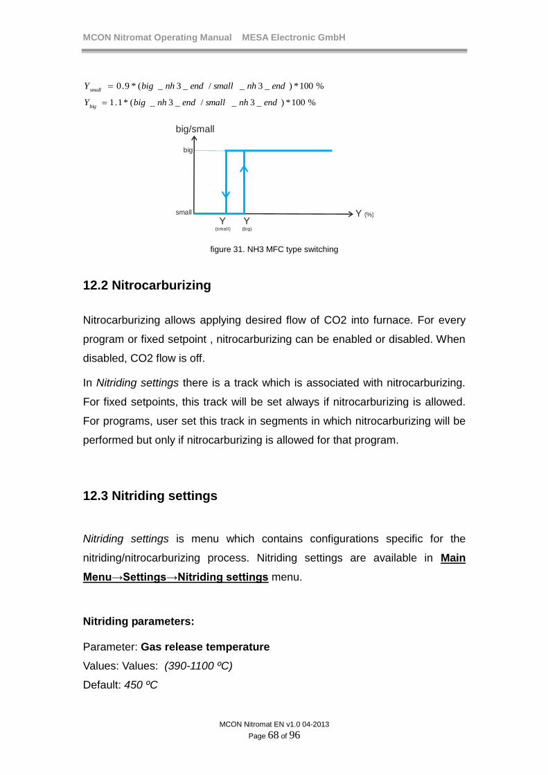
MCON Nitromat Operating Manual MESA Electronic GmbH
MCON Nitromat EN v1.0 04-2013
Page 68 of 96
%100*)_3_/_3_(*9.0 endnhsmallendnhbigYsmall
%100*)_3_/_3_(*1.1 endnhsmallendnhbigYbig
Y(small)
Y(big)
Y (%)
big/small
big
small
figure 31. NH3 MFC type switching
12.2 Nitrocarburizing
Nitrocarburizing allows applying desired flow of CO2 into furnace. For every
program or fixed setpoint , nitrocarburizing can be enabled or disabled. When
disabled, CO2 flow is off.
In Nitriding settings there is a track which is associated with nitrocarburizing.
For fixed setpoints, this track will be set always if nitrocarburizing is allowed.
For programs, user set this track in segments in which nitrocarburizing will be
performed but only if nitrocarburizing is allowed for that program.
12.3 Nitriding settings
Nitriding settings is menu which contains configurations specific for the
nitriding/nitrocarburizing process. Nitriding settings are available in Main
Menu→Settings→Nitriding settings menu.
Nitriding parameters: Parameter: Gas release temperature
Values: Values: (390-1100 ºC)
Default: 450 ºC

MCON Nitromat Operating Manual MESA Electronic GmbH
MCON Nitromat EN v1.0 04-2013
Page 69 of 96
Description: Minimum temperature required to allow gas flows (NH3, N2 and
CO2).
Parameter: Initial gasing
Values: Values: (0-100 m3)
Default: 5 m3
Description: Gas volume which must load the furnace before start program
control. Usually is not less than 5 time of the furnace volume.
Parameter: Init. gas if H2 <
Values: Values: (0-100 %)
Default: 0 %
Description: If zero (0%) initial gas is performed only if WKn > 0. If not zero,
initial gassing is started only if WKN >0 and measured H2-concentration < xx
%H2. This parameter is only effective for fixed setpoints. For programs, initial
gassing is always performed.
Parameter: Init. gasing time
Values: Values: (0-100 min)
Default: 10 min
Description: If no NH3 MFC presented, this parameter defines how long initial
gas phase will be active because there is no measurement of NH3 flow.
Parameter: Big NH3 DOUT
Values: (not set, dout 1, dout 2, dout 3 … dout n)
Default: not set
Description: Digital output which will be active when big NH3 MFC is used.
Parameter: Nitrocarb. track
Values: (track A, track B, track C, track D … track P)
Default: track N
MCON Nitromat Operating Manual MESA Electronic GmbH
MCON Nitromat EN v1.0 04-2013
Page 70 of 96
Description: Track which must be set to allow CO2 flow (nitrocarburizing)
when program runs, or when nitrocarburizing is enabled when fixed setpoint
used.
Parameter: Oxidating track
Values: (track A, track B, track C, track D … track P)
Default: track O
Description: Track which is active when program runs oxidating segment.
Parameter: Purging track
Values: (track A, track B, track C, track D … track P)
Default: track P
Description: Track which is active when program runs purging segment.
MCON Nitromat Operating Manual MESA Electronic GmbH
MCON Nitromat EN v1.0 04-2013
Page 71 of 96
12.4 Scaling Analog Out
Analog outout used to control mass flow controllers can be configured in Main Menu→Settings→Nitriding settings→ Scaling Analog OUT menu.
12.4.1 AOUT1- MFC NH3
This analog output is used for control both big and small NH3 MFC if analog control output is used for Kn control. (Kn control settings).
Parameters:
Parameter: NH3 small start
Values: (0 – 9.0 m3/h)
Default: 0 m3/h
Description: NH3 flow which produce 4 mA analog output for small NH3 MFC.
Parameter: NH3 small end
Values: (1 – 10.0 m3/h)
Default: 10 m3/h
Description: NH3 flow which produce 20 mA analog output for small NH3
MFC.
Parameter: NH3 big start
Values: (0 – 90.0 m3/h)
Default: 0 m3/h
Description: NH3 flow which produce 4 mA analog output for big NH3 MFC.
Parameter: NH3 big end
Values: (10 – 100.0 m3/h)
Default: 100 m3/h
Description: NH3 flow which produce 20 mA analog output for big NH3 MFC.

MCON Nitromat Operating Manual MESA Electronic GmbH
MCON Nitromat EN v1.0 04-2013
Page 72 of 96
12.4.2 AOUT2 and AOUT3 (MFC N2/CO2)
These analog outputs are used for control N2 or CO2 flow with mass flow controllers. WN2 and WCO2 are scaled to current output (4-20 mA) on AOUT2 and AOUT3 respectively. Values for these parameters depend on mass flow controllers flow ranges.
Parameters:
Parameter: Low value
Values: (0 – 30.0 m3/h)
Default: 0 m3/h
Description: Minimal WN2/WCO2 value which generates 4 mA output.
Parameter: High value
Values: (0 – 30.0 m3/h)
Default: 0 m3/h
Description: Maximum WN2/WCO2 value which generates 20 mA output.

MCON Nitromat Operating Manual MESA Electronic GmbH
MCON Nitromat EN v1.0 04-2013
Page 73 of 96
13. Communication
Communcication settings are available in the Main
Menu→Settings→Comm. config menu. In the communication configirations
menu there are submenus for every communication interface settings.
13.1 Com1 and Com2
Com1 is isolated communication interface which can be either MODBUS
master or PROFIBUS slave protocol depending on purchased unit.
There are several communication protocols which is implemented. ON the
table below is given overview of MCON Nitromat communication protocols
and their description.
PROTOCOL Interface Description
MODBUS Master Com1 or Com2 Used for connecting remote
peripherals such as I/O expanders,
actuators and for remote setpoints.
MODBUS Slave Com1, Com2 or
Ethernet
Connecting with masters which can
read and write parameters to device
and monitor device statuses and
measurement values remotely.
PROFIBUS Com1 Connecting to PROFIBUS network and
provide interface for writing and
reading common parameters and data.
List of addresses for the MODBUS Slave and PROFIBUS protocols can be
found in the C300 Communication protocols reference manual. For Modbus
Slave, addresses and commands are the same regardless of communication
interface.
Com1 and Com2 parameters
Parameter: Protocol

MCON Nitromat Operating Manual MESA Electronic GmbH
MCON Nitromat EN v1.0 04-2013
Page 74 of 96
Values: Values: (OFF, Modbus Master, Modbus Slave, PROFIBUS)
Default: OFF
Description: When OFF, this communication interface is not used. Com1
protocol can be only PROFIBUS (if device with PROFIBUS is ordered) or
Modbus Master, Modbus Slave if device with RS485/422 is ordered.
Next parameters are only available for non PROFIBUS protocol selected!
Parameter: Baud rate
Values: Values: (4800 bps, 9600 bps, 19200 bps, 38400 bps, 57600 bps,
11520 bps)
Default: 4800 bps
Description: Communication speed for non PROFIBUS prototols.
Parameter: Parity
Values: Values: (even parity, odd parity, no parity)
Default: even parity
Description: Parity bit configuration.
Parameter: Stop bits
Values: Values: (1 stop bit, 2 stop bits)
Default: 2 stop bits
Description: Number of stop bits in the serial communication frame.
Parameter: Address
Values: Values: (0-255)
Default: 1
Description: Device address for the on the communication interface. When
MODBUS Master is set, this address determine address of a remote device
which is pooled to obtain remote setpoints.
MCON Nitromat Operating Manual MESA Electronic GmbH
MCON Nitromat EN v1.0 04-2013
Page 75 of 96
13.2 Ethernet communication
Ethernet communication interface provides connectivity to the MODBUS
network as a slave or web server access to the device via web browser.
Parameter: DHCP
Values: Values: (checked, unchecked)
Default: checked
Description: If checked, then IP address, Gateway and subnet mask are
obtained from the DHCP server (automatically). When unchecked, user must
insert these values manually.
Parameter: IP address
Values: Values: (127.0.0.1 – 255.255.255.254)
Default: 192.168.1.110
Description: IP address of device
Parameter: Gateway IP
Values: Values: (127.0.0.1 – 255.255.255.254)
Default: 192.168.1.110
Description: Address of a gateway on which device is connected
Parameter: Subnet
Values: Values: (127.0.0.1 – 255.255.255.254)
Default: 192.168.1.110
Description: Subnet mask for the network on which the device is connected.
NOTE
When used as MODBUS Slave, Ethernet interface provides
the same MODBUS services on the same addresses as
when used on the Com1 or Com2 interface.
MCON Nitromat Operating Manual MESA Electronic GmbH
MCON Nitromat EN v1.0 04-2013
Page 76 of 96
To access the MCON Nitromat via web server first check the device IP
address (either entered or assigned by DHCP). Then type this address on the
web browser and web page with measurements will appear.

MCON Nitromat Operating Manual MESA Electronic GmbH
MCON Nitromat EN v1.0 04-2013
Page 77 of 96
14. User privileges
Device has 5 user levels which determine functions availability depending on
logged user privileges. After starting device, user need to logon to the device.
Logging process requires inserting appropriate username and password.
If no user logged, the only enabled menu is User Login available in the Main
Menu→Settings→System→User Login menu. In this menu, operator can
insert valid user name and password and thus get the appropriate user level
privilege which allows access to certain functions and parameters changing.
After inserting username and password, press Submit button to login with
inserted data. If the username and password are incorrect, an error message
appears. Access level of logged user is visible in the System informations
screen.
NOTE
If there is no users defined (when device is new), default
User level is always Level5 until You create some users.
If there are some users defined, device will always start
with Level0 privilege and You must log in to get higher
access level.
Logged user has its own user privilege which can be one of those: Level5,
Level4, Level3, Level2 or Level1. Level5 has the highest priority and user with
that privilege has all access rights. On the other side, Level1 allows only small
amount of functionalities to the user and it is used to prevent changing critical
system parameters by the unauthorized persons.
On the next table are listed device features and required user level for them to
be accessible.
Feature(Action) L5
L4
L3
L2
L1
L0
View Proces data X X X X X X
Chose setpoint(SP1,SP2…) X X X X
Edit setpoints X X

MCON Nitromat Operating Manual MESA Electronic GmbH
MCON Nitromat EN v1.0 04-2013
Page 78 of 96
Change programs data (segments and programs
name)
X X X
Run programs X X X X
Pause programs X X X X
Backup parameters X X X X
Backup programs X X X X
Change PID preset X X X X
Edit PID preset X X X
Factory reset settings X
Change communication parameters X X X
Change analog inputs parameters X X X
Change analog output scaling X X
Change nitriding settings X X
Change language X X X
Change temperature unit X
Change date and time X X X
Correct measurement X X
Start/Stop logging X X X X X
Edit loging settings X X X X
Transfer logged data to USB stick X X X X X
Edit alarms X X X X X
Fast edit setpoints(on screen typing) X X
Create new user X
Delete user X
Change user password X
Change own password X X X X X
Change user access level X
Touch screen calibration X X
Assign digital outputs to alarms, tracks etc X
Test digital outputs X

MCON Nitromat Operating Manual MESA Electronic GmbH
MCON Nitromat EN v1.0 04-2013
Page 79 of 96
14.1 Users management
User with highest privilege (Level5) has the ability to add new users, delete or
change user privilege of the existing users. Therefore for those users menu
item Users in the Main Menu→Settings→System→Users menu is enabled.
Pressing Users button opens Users screen where re displayed all user
accounts created on the device. There are maximum 10 users which can be
created. To create new user, press the button Add new
and insert desired
username, password and access level for new user. In the new user dialog
screen, press the Cancel button to back to the Users screen without adding
the new user. Regular returning to Users screen adds new users which will be
displayed last in the users list.
To change user’s password or user level, press EditEdit button which opens the
screen where you can insert new password or to select new user level.
Existing users can be deleted from the system by pressing the button. After
confirmation, user will be deleted from the system.
Users
mesa Level 5 Edit
John Level 1 Edit
Frederick Level 1 Edit
Peter Level 4 Edit
Reinhard Level 3 Edit
Add new
figure 32. Users screen
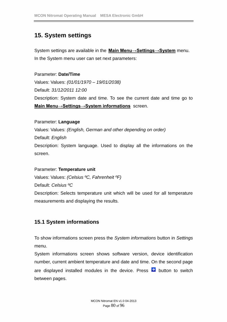
MCON Nitromat Operating Manual MESA Electronic GmbH
MCON Nitromat EN v1.0 04-2013
Page 80 of 96
15. System settings
System settings are available in the Main Menu→Settings→System menu.
In the System menu user can set next parameters:
Parameter: Date/Time
Values: Values: (01/01/1970 – 19/01/2038)
Default: 31/12/2011 12:00
Description: System date and time. To see the current date and time go to
Main Menu→Settings→System informations screen.
Parameter: Language
Values: Values: (English, German and other depending on order)
Default: English
Description: System language. Used to display all the informations on the
screen.
Parameter: Temperature unit
Values: Values: (Celsius ºC, Fahrenheit ºF)
Default: Celsius ºC
Description: Selects temperature unit which will be used for all temperature
measurements and displaying the results.
15.1 System informations
To show informations screen press the System informations button in Settings
menu.
System informations screen shows software version, device identification
number, current ambient temperature and date and time. On the second page
are displayed installed modules in the device. Press button to switch
between pages.

MCON Nitromat Operating Manual MESA Electronic GmbH
MCON Nitromat EN v1.0 04-2013
Page 81 of 96
System informations
Firmware version 1.00
Amb. temp : 28.12 ºC
Date/Time 08/08/2013 03:44:22
UID :ed1931 - 7b01 - e33a4d3445
S/N : 1
User level: Level5
I/O Modules
MODULE 1 AOM
MODULE 2 AOM
MODULE 3 Relay3
MODULE 4 Empty
MODULE 5 Empty
MODULE 6 Empty
figure 33. System informations and installed modules
15.2 System functions
System functions are available in the Main Menu→Settings→System menu.
Functions are available only if user has the highest access level. See User
privileges chapter for details.
15.2.1 Touch screen calibration
To improve touch screen accuracy it is good practice to calibrate the screen.
On the calibration screen, press the cross which appears on the upper-top
position of the screen. After pressing, cross moves to the center of the screen
and then again on the bottom-right. After pressing third calibration point,
device automatically returns from the calibration screen and remembers
calibration data. Therefore calibration will take effect immediately (without
restarting the device).
If the screen is not calibrated properly, user may not be able to activate
calibration. In that case, a keyboard must be used to go to the System menu
and to press the Calibration screen feature.
To achieve better calibration accuracy it is good practice to use a pen for
calibration when pressing the calibration points.
Touch the cross by stylus.
figure 34. Touch screen calibration

MCON Nitromat Operating Manual MESA Electronic GmbH
MCON Nitromat EN v1.0 04-2013
Page 82 of 96
15.2.2 Factory settings
Press Factory settings button in System menu to reset all parameters to their
default values. This will also delete all user accounts.
When loading factory settings is complete, device will resets automatically.
15.2.3 Parameters backup
MCON Nitromat has a feature to save and load parameters values to USB
stick.
To save or load parameters, USB stick must be inserted, otherwise an error
message will be shown. This feature is forbidden in RUN mode.
To save parameters to USB stick press the Save config to USB button in the
System menu. It will save all parameters value into n300_cfg.bin file.
To load parameters from the USB stick press the Load config from USB
button in the System menu. Then the device will search for the n300_cfg.bin
file and load file data to restore all parameters settings. After loading
parameters, device will automatically restart.
15.2.4 Programs backup
Programs backup are similar to the parameters backup. It can be performed
with Save programs to USB and Load prog. from USB functions in the System
menu. This feature is also forbidden if device is in RUN mode.
After loading programs, device will not restart!
15.2.5 Firmware update
MCON Nitromat software can be updated with new one by using USB
memory stick. It is recommended that user checks if there is new version of
device software for updating. To find the newest firmware version contact the
producer.
Firmware file name is image.s19 and it must be placed on root directory in the
USB memory stick.

MCON Nitromat Operating Manual MESA Electronic GmbH
MCON Nitromat EN v1.0 04-2013
Page 83 of 96
To start firmware update reset the device (turning on then off power supply or
by pressing Reset button in System menu) then immediately press and hold
Enter taster. Device will show white screen and TX LED on. Then insert USB
stick with firmware file which will automatically start updating process. During
firmware updating process, TX led will flashes fast until the end of the
updating. After update finishes, device will started automatically running new
firmware

MCON Nitromat Operating Manual MESA Electronic GmbH
MCON Nitromat EN v1.0 04-2013
Page 84 of 96
16. Logging
This feature allows measurement data to be logged during the control
process. Every log session stores data into one file. Log session can be
started manually or at desired time. Also it can be stopped manually or
automatically. When log session ends, log file is created and it can be
transferred to USB stick.
Logging functions are available in logging screen: Main Menu→Logging
Logging
Logging in progress
Stop Usb transfer Settings
Duration : 00:22:43
Start Time : 09/02/2013 13:00:00
End Time : 09/02/2013 18:00:00
Log files : 12
figure 35. Logging screen
To start logging go to Main Menu→Logging screen and press Start button. If
there is no enough memory space for new logging file, an error message will
be displayed.
Logging session can be ended by pressing Stop button or at desired time
depending on logging settings.
When the logging is not in progress (logging status label shows Logging Off),
user can transfer all log files onto USB stick by pressing USB transfer button.
Before this operation you must be sure that the USB stick is properly inserted.
Logged files will be transferred to USB stick root directory.
NOTE
After transferring log files to USB, they will be deleted from
the device.

MCON Nitromat Operating Manual MESA Electronic GmbH
MCON Nitromat EN v1.0 04-2013
Page 85 of 96
Logging parameters:
To configure logging parameters press the Settings button which opens menu
with logging settings. There are next logging settings which can be
configured:
Parameter: Log info
Values: Values: (name up to 15 characters)
Default: Log info
Description: Symbolically represents log session. This info will be visible when
log file is loaded via dedicated PC software.
Parameter: Logging mode
Values: Values: (Manual, Auto Start, Auto Stop, Auto Start/Stop)
Default: Manual
Description: Manual – user directly starts and stops logging
Auto Start – logging automatically starts at desired time and stops
manually
Auto Stop – logging manually started and automatically stopped
at desired time
Auto Start/Stop – logging automatically started and automatically stopped at
desired time
Parameter: Sample time
Values: Values: (1 – 1000 S)
Default: 5 S
Description: Time interval on which new measurement value will be captured
and logged to a file.
Parameter: Start Time
Values: Values: (01/01/1970 – 19/01/2038)
Default: 31/12/2011 12:00
Description: When the Auto Start or Auto Start/Stop mode is selected, this
time determine when to start new logging session.
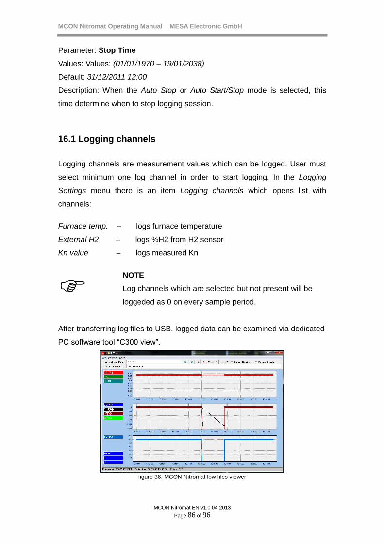
MCON Nitromat Operating Manual MESA Electronic GmbH
MCON Nitromat EN v1.0 04-2013
Page 86 of 96
Parameter: Stop Time
Values: Values: (01/01/1970 – 19/01/2038)
Default: 31/12/2011 12:00
Description: When the Auto Stop or Auto Start/Stop mode is selected, this
time determine when to stop logging session.
16.1 Logging channels
Logging channels are measurement values which can be logged. User must
select minimum one log channel in order to start logging. In the Logging
Settings menu there is an item Logging channels which opens list with
channels:
Furnace temp. – logs furnace temperature
External H2 – logs %H2 from H2 sensor
Kn value – logs measured Kn
NOTE
Log channels which are selected but not present will be
loggeded as 0 on every sample period.
After transferring log files to USB, logged data can be examined via dedicated
PC software tool “C300 view”.
figure 36. MCON Nitromat low files viewer

MCON Nitromat Operating Manual MESA Electronic GmbH
MCON Nitromat EN v1.0 04-2013
Page 87 of 96
17. Control principle Temperature control can be performed by either PID or On/Off control, while
Kn control is only PID. When PID is used, actuator can be controlled by one
digital output (2 state output), 2 digital outputs (3 state output) or with analog
output (if present). For On/Off control type, only digital outputs are available
for controlling the actuator.
N2 and CO2 flows are controlled with mass flow controllers on the AOUT2
and AOUT3.
17.1 PID control
For PID control desired process value or setpoint (SP) is compared with
current process value measured from the process (PV). According to
difference between SP and PV and PID parameters, PID loop output is
generated (Y). Output value (Y) can be from -100 % to +100%. Y is negative
when the PV is greater than the septoint (SP) and the 3 state output is
selected in PID preset parameters.
Positive Y (with range from 0 to 100%) is directly proportional to the amount of
drive which must be applied to the actuator on output 1.
Negative Y (from 0 to -100%) is directly proportional to the amount of drive
which must be applied to the actuator on output 2.
When the Y = 0 no actuator will be activated.
figure 37. Control block diagram
PID value Y depends on error and PID parameters:
DIPY
where:
MCON Nitromat Operating Manual MESA Electronic GmbH
MCON Nitromat EN v1.0 04-2013
Page 88 of 96
P – Proportional term which depends on current error
I – Integral term which depends on error duration in the integral time interval
D – Derivative term which depends on the short time error fluctuations
PID terms are calculated using process error e and parameters.
Error is defined as:
PVSPe
Proportional term P
Proportional term is proportional to the process error (e) multiplied with
proportional band (PB)
PBeP
For increasing sensitivity to error, PB must be increased.
There are 2 proportional band parameters. One is required for heating/valve
and second is only effective for 3 state outputs (cooling) in the cooling phase.
Example for Kn control:
If PB1 = 100%/Kn, PB2 = 50%/Kn and SP = 5 Kn for the measured Kn of
4.8, error will be 0.2 Kn and P term 0.2*100 = 20%
If measured Kn is 5.2 error will be also 0.2 but negative. In that case P term
will be zero. For temperature control, negative error will result in negative P
term which then control cooling phase.
Integral term
Integral term is very important for the process control in order to avoid “steady
state” error which occurs when controller cannot reach setpoint value if only
proportional term is used. For that reason integral term will add extra control
which will compensate steady state error.
Integral term depends on integral time (Ti) parameter and error sum during
time.
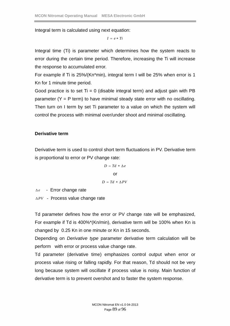
MCON Nitromat Operating Manual MESA Electronic GmbH
MCON Nitromat EN v1.0 04-2013
Page 89 of 96
Integral term is calculated using next equation:
TieI
Integral time (Ti) is parameter which determines how the system reacts to
error during the certain time period. Therefore, increasing the Ti will increase
the response to accumulated error.
For example if Ti is 25%/(Kn*min), integral term I will be 25% when error is 1
Kn for 1 minute time period.
Good practice is to set Ti = 0 (disable integral term) and adjust gain with PB
parameter (Y = P term) to have minimal steady state error with no oscillating.
Then turn on I term by set Ti parameter to a value on which the system will
control the process with minimal over/under shoot and minimal oscillating.
Derivative term
Derivative term is used to control short term fluctuations in PV. Derivative term
is proportional to error or PV change rate:
eTdD
or
PVTdD
e - Error change rate
PV - Process value change rate
Td parameter defines how the error or PV change rate will be emphasized,
For example if Td is 400%*(Kn/min), derivative term will be 100% when Kn is
changed by 0.25 Kn in one minute or Kn in 15 seconds.
Depending on Derivative type parameter derivative term calculation will be
perform with error or process value change rate.
Td parameter (derivative time) emphasizes control output when error or
process value rising or falling rapidly. For that reason, Td should not be very
long because system will oscillate if process value is noisy. Main function of
derivative term is to prevent overshot and to faster the system response.

MCON Nitromat Operating Manual MESA Electronic GmbH
MCON Nitromat EN v1.0 04-2013
Page 90 of 96
17.2 Discrete control output
Control output value Y (in literature well known as MV – manipulation value) is
given in percents which must be translated to digital outputs states. For this
transformation, important parameter is Cycle time. Cycle time defines how Y
value is translated to actuator activation time.
For ex. if Y=40% and Cycle time is 10 seconds, digital output for heating or
gas valve will be activated for 4 seconds and turned off 6 seconds.
When 3 state output is set (heating) Y can be negative. In that case is used
another Cycle time (cooling cycle time) parameter which is scaled to Y
absolute value.
figure 38. Control outputs activation
In the example controlling diagram above is showed how the actuators are
turned on and off depending on difference between process value and
setpoint. In the time interval (1), PV is much lower than setpoint, so heating
output must be turned on more than half of the cycle time. During heating,
temperature (process value) raises above setpoint but in the interval (2)
heater is turned off and temperature stars to fall until expiration of cycle time1
which is defined for heating only. At the beginning of second cycle (3),
process value is slightly above setpoint value but heating will again turned on
because of accumulated error in integral term. This cause shorter activation

MCON Nitromat Operating Manual MESA Electronic GmbH
MCON Nitromat EN v1.0 04-2013
Page 91 of 96
the heating actuator until interval (4) when temperature starts to fail again.
After second cycle time expired (5), process value is notably greater than
setpoint including dead band (see Deadband parameter). This means that
system must activate cooling actuator in cycle time 2 (which is defined for
cooling and air actuator as parameter). Cooling cause the temperature lowers
faster than in case when no cooling is activated which can be noted by
comparing interval (5) and (6) process value trend. In the interval (7), after first
cycle time2 interval, temperature is again below setpoint and heating must be
turned on again. Out 2 is only activated if proper control output is set (3 state
output).
17.3 On/Off control
This is the simplest control type which is implemented in the device and only
available for temperature control. When this control type is used, all PID
parameters will be disabled because they have no meaning for this type of
control. For On/Off control type is important only Upper Hysteresis and Lower
Hysteresis parameters.
When loop output is configured to 2 states, control output will be on when
temperature is below setpoint (SP) + Lower_Hysteresis. Actuator will be
turned off when PV becomes greater than SP + Upper Hysteresis.
OUT1
FLU
SH
ING
FL
US
HIN
G
PV
SP
Upper hysteresis
Lower hysteresis
figure 39. On/Off control for 2 state output
– Lower_Hysteresis and cooling is activated when PV becomes greater than
SP + Upper_Hysteresis. Actuators are turned when PV reach setpoint.
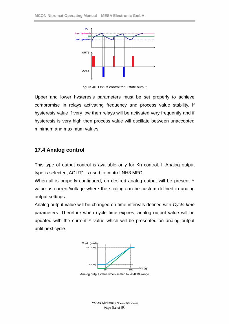
MCON Nitromat Operating Manual MESA Electronic GmbH
MCON Nitromat EN v1.0 04-2013
Page 92 of 96
OUT1
FLU
SH
ING
FL
US
HIN
G
PV
SP
Upper hysteresis
Lower hysteresis
OUT2
figure 40. On/Off control for 3 state output
Upper and lower hysteresis parameters must be set properly to achieve
compromise in relays activating frequency and process value stability. If
hysteresis value if very low then relays will be activated very frequently and if
hysteresis is very high then process value will oscillate between unaccepted
minimum and maximum values.
17.4 Analog control
This type of output control is available only for Kn control. If Analog output
type is selected, AOUT1 is used to control NH3 MFC
When all is properly configured, on desired analog output will be present Y
value as current/voltage where the scaling can be custom defined in analog
output settings.
Analog output value will be changed on time intervals defined with Cycle time
parameters. Therefore when cycle time expires, analog output value will be
updated with the current Y value which will be presented on analog output
until next cycle.
FL
US
HIN
G
Vout (Iout)
10 V (20 mA)
2 V (4 mA)
Y (%)20% 80 %
Analog output value when scaled to 20-80% range

MCON Nitromat Operating Manual MESA Electronic GmbH
MCON Nitromat EN v1.0 04-2013
Page 93 of 96
18. Specifications
Construction: - ABS DIN ¼ case for front mounting - Type of protection IP54 - Dimensions 96 x 96 x 111 mm
Power supply: - AC 85VAC…265VAC, 50-60Hz or DC 10VDC…36VDC. Power consumption 15VA Display: - Color TFT display, 320 x 240 px, 16it, 3.5’ with resistive touch screen Operation: - Touch screen menu guided and and/or four keys (up/down/enter/escape) Control loops: - 2 control loops - 3 control parameters preset per each loop - 2 open loop controls for N2 and CO2 flow - PID or On/Off control type - Control output types: heating/cooling for temperature control and digital or analog for Kn control. - N2/CO2 flow control with MFC - Custom assigning digital outputs for control Setpoints: - 4 fixed setpoints, external and remote setpoint - 99 programs with Kn and furnace temperature setpoints. - Up to 24 segments per program - 16 tracks per segment - Custom assigning digital output for every track Nitriding options: - Kn calculation with %H2 measurement and N2/CO2 flow - small or/and big NH3 MFC support - oxidating, purging and nitrocarburizing in desired program steps - initial gassing and gas blocking features Alarms: - Up to 4 user defined alarms for monitoring measurement values and change rates. - Custom assigning digital outputs for alarms Logging: - Logging sample time from 1 to 1000 seconds - Up to 20 log files can be stored to internal memory. - Logging on user demand or time activated.

MCON Nitromat Operating Manual MESA Electronic GmbH
MCON Nitromat EN v1.0 04-2013
Page 94 of 96
- Transferring log data to USB stick - Special software for viewing log data User access levels: - Up to 10 user accounts can be stored - 6 access level to grant privilege to users Communication interfaces: - Ethernet - isolated RS485/422 (optional) - PROFIBUS (optional) - non isolated RS485/422 (standard) Supported protocols: - MODBUS Master RTU or TCP - MODBUS Slave RTU or TCP - Webserver - PROFIBUS Analog inputs: 5 or 7 isolated analog inputs - AIN1 : thermocouple (B,C,E,J,K,L,M,N,R,S,T) / voltage 0-100mV - AIN2: H2 sensor (4-20 mA) - AIN3: N2 flow (4-20 mA) - AIN4: NH3 flow (4-20 mA) - AIN5: CO2 flow (4-20 mA)
Analog inputs ranges:
Type Measuring range Generating accuracy
resolution
TC B - PtRh-Pt6% 250...1820°C <3ºC 0.15ºC
TC C - W5%Re-W26%Re 0...2315°C <2°C 0.2ºC
TC E - NiCr-CuNi -200...1000°C <2ºC 0.05ºC
TC J - Fe-CuNi -210...1200°C <2ºC 0.06ºC
TC K - NiCr-Ni -200...1350°C <2ºC 0.06ºC
TC L - Fe-CuNi DIN -200...900°C <2ºC 0.06ºC
TC M - NiMo/NiCo -50...1410°C <2ºC 0.06ºC
TC N - Nicrosil-Nisil -200...1300°C <2ºC 0.1ºC
TC R - PtRh-Pt13% -50...1760°C <2ºC 0.1ºC
TC S - PtRh-Pt10% -50...1760°C <2ºC 0.1ºC
TC T - Cu-CuNi -200...400°C <2ºC 0.1ºC
Cold junction sensor -25ºC…+85ºC 1,5ºC 0.1ºC
Current inputs -5mA…+25mA 0.1% 1uA
Analog outputs: - 3 analog outputs for NH3, N2 and CO2 mass flow controllers - AOUT1 scaled for both big and small NH3 MFC Analog outputs ranges
Digital inputs:
Ratings Max. Load Resolution Accuracy
0mA…20mA 4mA…20mA
<500 16 bit 0.05%
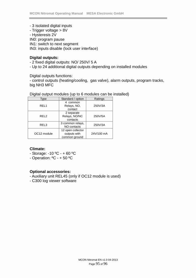
MCON Nitromat Operating Manual MESA Electronic GmbH
MCON Nitromat EN v1.0 04-2013
Page 95 of 96
- 3 isolated digital inputs - Trigger voltage > 8V - Hysteresis 2V IN0: program pause IN1: switch to next segment IN3: inputs disable (lock user interface) Digital outputs: - 2 fixed digital outputs: NO/ 250V/ 5 A - Up to 24 additional digital outputs depending on installed modules Digital outputs functions: - control outputs (heating/cooling, gas valve), alarm outputs, program tracks, big NH3 MFC Digital output modules (up to 6 modules can be installed)
Climate: - Storage: -10 ºC - + 60 ºC - Operation: ºC - + 50 ºC Optional accessories: - Auxiliary unit REL45 (only if OC12 module is used) - C300 log viewer software
Type Standard / option Ratings
REL1 4 common Relays, NO,
contact 250V/3A
REL2 2 separate
Relays, NO/NC contacts
250V/5A
REL3 3 common relays,
NO contacts 250V/3A
OC12 module 12 open collector
outputs with common ground
24V/100 mA

MCON Nitromat Operating Manual MESA Electronic GmbH
MCON Nitromat EN v1.0 04-2013
Page 96 of 96
18.1 Isolation diagram
figure 44.MCON Nitromat isolation diagram


