125 Szybkobiene Pojazdy Gsienicowe (39) nr 1, 2016 Marian HOLOTA, Dr Monika KURPAS – Orodek Badawczo-Rozwojowy UrzdzeMechanicznych "OBRUM" sp. z o.o., Gliwice Marian HOLOTA Monika KURPAS CRITERIA AND RULES IN THE DESIGN OF MODERN COMBAT VEHICLES WITH LARGE-CALIBRE ARMAMENT PART 1 Abstract. The paper presents methods of acquiring armoured equipment based on valid decisions of the Ministry of Defence. A description is given of the method of acquiring new equipment based on R&D studies along with the definitions of general components of the Feasibility Study, parametric criteria, scope of analyses and studies required for adopting a general structural arrangement of the concept design. Special reference is made to parametric analyses, with the adopted evaluation criterion being the meeting of future user's expectations and the effect of the solution on the general structural arrangement. Keywords: military equipment, combat vehicles, versatile modular tracked platform, modernization of land forces, armoured and mechanized troops, tracked vehicles, feasibility study, concept design, vehicle configuration. 1. INTRODUCTION Designing modern combat vehicles with large-calibre armament requires specialist knowledge of the considerations of implementing research projects, of the methods of managing the design process, performing criterion and comparative analyses, platform manufacture (construction) and testing in terms of compliance with the tactical and technical parameters of the vehicle specified in the Operational Requirements (WO), Initial Tactical and Technical Specifications (WZTT) or Tactical and Technical Specifications (ZTT) as the basic documents constituting the source of information about the future user's expectations. Combat vehicles with large-calibre armament include mainly: – light, medium and heavy tanks (MBT) with guns calibre 120 and 125 mm, and announced weapons, calibre 140 and 155 mm; – fire support vehicles; – tank destroyers; – gun-howitzers on tracked carriers; – delf-propelled mortars calibre over 120 mm. Bearing in mind the requirement of a 30-years lifetime of the equipment, one should assume that the approach to the design of new vehicles must involve the application of technical solutions that are at least a decade ahead of the current development trends.
Transcript
124 125Szybkobie�ne Pojazdy G�sienicowe (39) nr 1, 2016
Marian HOLOTA, Dr Monika KURPAS – O�rodek Badawczo-Rozwojowy Urz�dze� Mechanicznych "OBRUM" sp. z o.o., Gliwice
Marian HOLOTA Monika KURPAS
CRITERIA AND RULES IN THE DESIGN OF MODERN COMBAT VEHICLES WITH LARGE-CALIBRE ARMAMENT
PART 1
Abstract. The paper presents methods of acquiring armoured equipment based on valid decisions of the Ministry of Defence. A description is given of the method of acquiring new equipment based on R&D studies along with the definitions of general components of the Feasibility Study, parametric criteria, scope of analyses and studies required for adopting a general structural arrangement of the concept design. Special reference is made to parametric analyses, with the adopted evaluation criterion being the meeting of future user's expectations and the effect of the solution on the general structural arrangement.
Keywords: military equipment, combat vehicles, versatile modular tracked platform, modernization of land forces, armoured and mechanized troops, tracked vehicles, feasibility study, concept design, vehicle configuration.
1. INTRODUCTION
Designing modern combat vehicles with large-calibre armament requires specialist knowledge of the considerations of implementing research projects, of the methods of managing the design process, performing criterion and comparative analyses, platform manufacture (construction) and testing in terms of compliance with the tactical and technical parameters of the vehicle specified in the Operational Requirements (WO), Initial Tactical and Technical Specifications (WZTT) or Tactical and Technical Specifications (ZTT) as the basic documents constituting the source of information about the future user's expectations.
Combat vehicles with large-calibre armament include mainly:
– light, medium and heavy tanks (MBT) with guns calibre 120 and 125 mm, and announced weapons, calibre 140 and 155 mm;
– fire support vehicles; – tank destroyers; – gun-howitzers on tracked carriers; – delf-propelled mortars calibre over 120 mm. Bearing in mind the requirement of a 30-years lifetime of the equipment, one should
assume that the approach to the design of new vehicles must involve the application of technical solutions that are at least a decade ahead of the current development trends.
126 127Marian HOLOTA, Monika KURPAS
Forecasting the development trends correlated with the generation of new technologies and innovation and implementing new solutions in the design process should, in order to achieve the best end result, be backed by knowledge acquired from experience (mentoring). This trend seems to be highly useful, especially in the area of designing combat vehicles for the needs of armoured units. Over 45 years of invaluable experience that OBRUM has gained in designing high-speed tracked vehicles of different applications (including combat vehicles), is an asset worth exploiting.
2. PURPOSE OF THE PAPER
This paper, aimed at presenting the criteria and rules of design of modern combat vehicles, should be treated as one that inaugurates a series of articles to be published in future issues of "Fast Tracked Vehicles". This series of articles will cover the following topics:
� combat vehicle development trends and effect of weight of a vehicle on its tactical and technical specifications, including ballistic resistance; these problems are the topic of this paper;
� general structural arrangement of the vehicle and parametric evaluation of principal solutions and conclusions;
� ability to negotiate terrain obstacles, including water obstacles; � primary armament and auxiliary systems; � vehicle survivability in the contemporary battlefield. The proposed series of articles is a summary of own experience from R&D and
implementation projects and does not make reference to classical literature.
3. METHODS OF ACQUIRING NEW MILITARY EQUIPMENT (MEq)
Under the current provisions of Decision 479/MON [2], new MEq may be acquired for the Polish Armed Forces by way of, for instance:
� direct purchase (also from a foreign seller), provided that Operational Requirements (WO) are met;
� purchase and modification of equipment to meet user requirements; the process requires some research and development input;
� development of new MEq by the national defence industry in an R&D cycle.
Regardless of the adopted method, the acquirement of new MEq for the Polish Armed Forces will have some, greater or lesser, effect on the national economy. Although the direct or indirect purchase enables faster acquirement of MEq, it does involve some constraints. These have been described in the literature [3].
The carrying out of a complete development cycle of a MEq project provides the national economy with an added value from each manufactured product at a level of 60 to 65%, whereas the adoption of the so-called ready-made (foreign) solutions, with the need to adapt them to meet WO, reduce the level of added value to ca. 5 to 10%.
The methods of acquiring MEq should take into account not only the development of the basic solution, but primarily its further development and future use that will provide added value to the national economy from every manufactured product in the coming years.
The process of acquiring MEq will be traced based on design tasks in the R&D phase.
126 127Criteria and trends in the design of modern combat vehicles...
3.1 Feasibility Study - an opening document for the Concept Design
The Feasibility Study is a kind of compendium of knowledge about the project. In addition to a technical analysis of feasibility (implementability), information and recommendations on the selection of the solution that meets the buyer's needs (defined in WO) most effectively, it also contains information on:
� current state of technology, including the status of equipment of the armies of the world;
� availability (or lack of it) of equipment that meets WO; � trends in development projects conducted in the world.
Documents on current research programs conducted in the area of combat vehicles, including those with large-calibre weapons, analyzed in the literature [3,4], indicate that the trend to promote modular structures in MEq development is maintained. Modular structure may include the following:
� platforms as carriers, i.e.: Universal Modular Tracked Platform (UMPG); � mission systems (weapon systems, including large-calibre weapons), i.e.: mission
(functional) system in one of the following forms: � turret weapon system (artillery or missile system, including unmanned
systems); � turretless weapon systems, such as: surface-to-surface or surface-to-air missile
launchers; � special types:
• secondary armament, for instance: Remotely Operated Weapon Station with exchangeable equipment (12.7 mm large-calibre machine gun; 7.62 mm universal machine gun; automatic 40 mm grenade launcher, etc.) controlled from the inside of the vehicle;
• equipment typical of a reconnaissance vehicle: – engineer reconnaissance; – chemical reconnaissance; – recovery reconnaissance;
• command and logistic module: – command; – sanitary; – ammunition, supplies; – topographical fix; – radar equipment and antiaircraft systems: – logistic support, etc.
The above task can only be completed after vehicle configuration is defined and approved. Vehicle configuration includes:
– specifying all structural units that meet the requirements; – defining functional interfaces between the units; – determining the dimensions and weights; – plotting mass parameters in an OXYZ Cartesian coordinate system (Fig. 1).
128 129Marian HOLOTA, Monika KURPAS
Fig. 1. Spatial physical model of combat vehicle in the adopted coordinate system [5]
For the vehicle to reach operational capability that meets the requirements of the modern battlefield, it is necessary to develop a solid configuration already at the stage of preparing the Feasibility Study. This should enable to:
– define the total weight as a sum of partial weights; – define the centre of mass and mass moment of inertia.
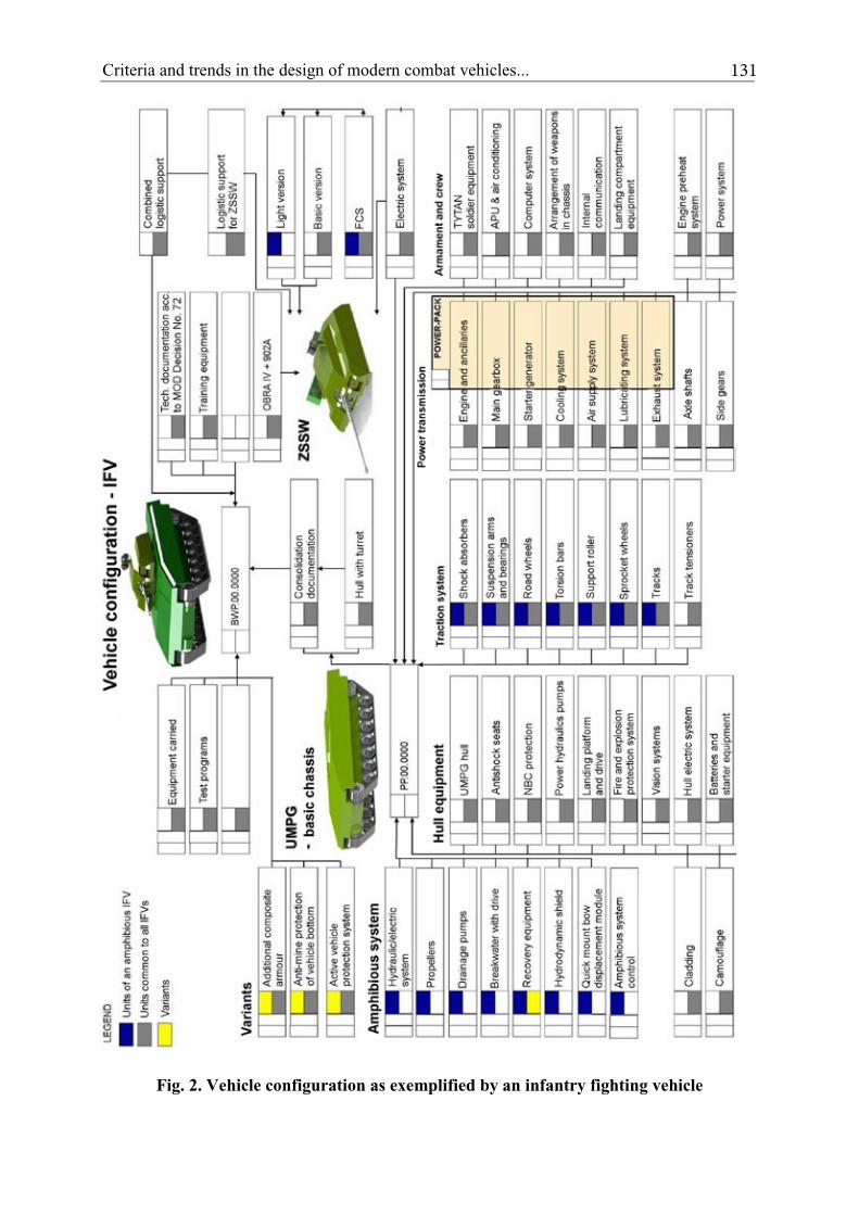
Vehicle configuration is the basis of design and engineering tasks and is essential to the implementation of the project. It is briefly represented in Fig. 2 which, upon approval by the Administrator constitutes basis for:
– determining the necessary work input by the design engineers; – determining logistic requirements; – working out testing methodology and programs; – setting up a list of engineering groups; – determining participants in the design process; – setting up a list of suppliers and imported parts; – acquiring geometric mass models, e.g.: 3D models of units and assemblies; – setting up cooperation relations and dates for the delivery of metal and highly-
processed materials; – determining equipment distribution and mass analyses, mainly centre of mass
and mean specific loads; – determining mechanical, electrical, hydraulic power balances.
An example of a combat vehicle configuration diagram which includes main units and components of systems enabling further design work is shown in Fig. 2. Three variants of the
128 129Criteria and trends in the design of modern combat vehicles...
original concept of an Infantry Fighting Vehicle based on the Universal Modular Tracked Platform (UMPG) were used as an example: light – floating, medium and heavy [4], [6, 7]). The configuration diagram includes all the functional interrelations between the main components, forming a basis for further concept studies. It should then be subject to continuous verification of component delivery requirements, etc.
The objective of all of the design work aimed at optimizing the arrangement of the units and components of the vehicle is to bring the geometric centre as close as possible to the centre of mass, taking into account product ergonomics.
It is worth noting here that OBRUM pioneered modular solutions in vehicle design in the 1980s with SPG-1 (1M) (Fast Tracked Vehicle) entering service in the Polish Armed Forces and abroad as carrier for radar station NUR-21 (DANIELA). Experience gained was employed in the design of other vehicles of modular structure:
� Recovery Vehicle WZT-3 and Engineering and Road Vehicle MID, both based on tank T-72/PT91, and
� Recovery Vehicle WZT-4 and Engineering and Road Vehicle MID M, offered for exports.
4. TRENDS IN THE DEVELOPMENT OF MODERN COMBAT VEHICLES WITH LARGE-CALIBRE ARMAMENT
The development of Main Battle Tanks (MBTs) is divided into generations, designated I ... III+. Two definitions of the classification have been formed. A group (according to authors of [8, 9]) is considered a generation when design solutions applied in the MBT are characterized by similar parameters, the decisive criterion being only the level achieved, not the date of implementation (modification). According to [10], [11], generation of a vehicle is established on the basis of the date of entry into service of the first basic instance of the vehicle. Even a thorough modification of a vehicle does not advance it to the next generation.
In the case of both definitions, all the named generations have a similar general structural arrangement with 3- or 4-member crews located in body or crew turret with additional ammunition located in the undercarriage.
Neither of the two "MBT generation" definitions refers to the general structural arrangement.
New generation MBT projects currently being developed or already abandoned include such designs as:
– Kharkov's "Molot" (Object 477), successor of "Buntor" tank (Object 490) with a 152 mm gun, "Irtysh" FCS and low-profile turret the mobility of which is assessed as better than that of T-80 UD (Object 478);
– T-14 Armata (Russian new generation tank) based on Object 195 (two prototypes between 1999 and 2002) with intense studies up to 2006, after which the project was cancelled. One of the reasons for abandoning the project were the transformations of the post-Cold War battlefield. Some of the concepts have proved correct, some required further development. The general structural arrangement represents a three-member crew located in a separate
130 131Marian HOLOTA, Monika KURPAS
armoured capsule positioned within the tank body behind a front armour module. An unmanned remotely controlled turret with a relatively small "shell" housing a 125 mm gun is located over the combat compartment. The basic armour of the turret "shell" provides protection against 30 to 57 mm automatic gun shells. The basic armour of the chassis front may be assessed as equivalent to 840 mm RHA;
– upgrade propositions for the Polish Lepoards MBT Revolution.
Projects that currently seem to be at their final stage include the Korean MBT K2 and the Turkish AltaY.
Fourth (IV) MBT generation is a group of tanks studies on which are currently under way. This generation will have the following characteristics:
a) reduced weight (suitable for air transportation); b) propagation of three-member crews (with a tendency to form two-member crews); c) automated processes (track tensioning, gun loading, target locating and tracking,
etc.); d) system computerization; e) modular structure; f) propagation of modular additional armour; g) unmanned turret systems; h) standardized and unified vehicle units or complete vehicles; i) use of advanced materials.
Development of armoured vehicles based on universal tracked platforms implemented in government programmes is discussed in detail in another paper [12].
130 131Criteria and trends in the design of modern combat vehicles...
Fig. 2. Vehicle configuration as exemplified by an infantry fighting vehicle
132 133Marian HOLOTA, Monika KURPAS
5. VEHICLE PROTECTION
The configuration of the planned vehicle carrying weapons that include currently used 120 and 125 mm guns or 140 and 155 mm guns under development (Russia) should provide for the use of solutions that meet the criterion of high survivability of the crew. Schematically, the criteria for the actions and possible means of attaining an optimum parameter are presented in Fig. 3.
Beijing
Fig. 3. Criteria for design activities and equipment that affect battlefield survivability of a vehicle [13, 14]
Additional armour is one of the means of protecting vehicles in combat operations (the "counteract penetration" criterion). Some of the design solutions applied in additional armour include:
– reactive armour, serving mainly to protect the vehicle against antitank guided missiles, shaped charge gun shells, antitank grenades;
– protection against IEDs; – passive armour, usually installed as additional armour over certain parts of the vehicle
with different required levels of protection; these are mainly used to protect the vehicle against the effects of small arms fire, both single shots and sustained fire, of anti-tank missiles, including sabot shells, and of fragments of artillery shells and grenades;
– both passive and active type solutions.
Requirements for the efficiency of ballistic protection of passive armour are specified in the STANAG 4569, Ed. III standard, which lists seven protection levels described using resistance to typical hits and blasts.
132 133Criteria and trends in the design of modern combat vehicles...
Procedures for evaluating the protection level of armoured vehicles are described in standardization document AEP-55.
Due to space limitations of this article, the reader is referred to a detailed discussion of the design of the various types of armour in the literature [15 – 21].
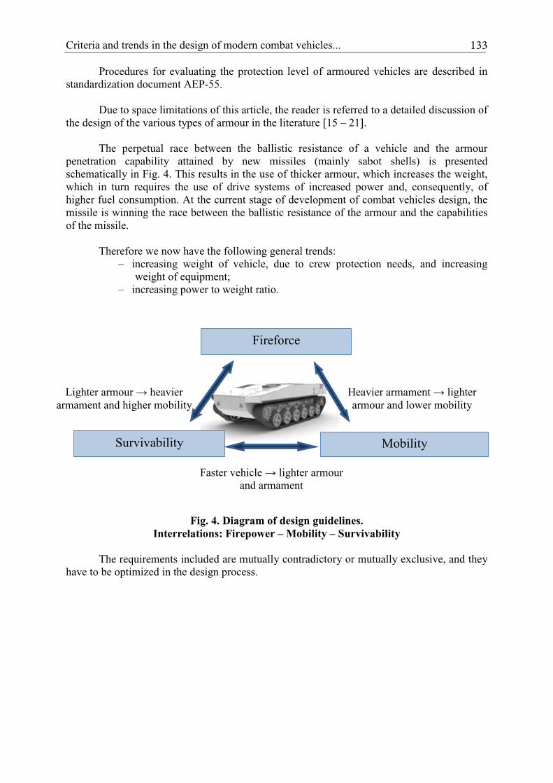
The perpetual race between the ballistic resistance of a vehicle and the armour penetration capability attained by new missiles (mainly sabot shells) is presented schematically in Fig. 4. This results in the use of thicker armour, which increases the weight, which in turn requires the use of drive systems of increased power and, consequently, of higher fuel consumption. At the current stage of development of combat vehicles design, the missile is winning the race between the ballistic resistance of the armour and the capabilities of the missile.
Therefore we now have the following general trends:
– increasing weight of vehicle, due to crew protection needs, and increasing weight of equipment;
The requirements included are mutually contradictory or mutually exclusive, and they have to be optimized in the design process.
Mobility Survivability
Faster vehicle � lighter armour and armament
Fireforce
Lighter armour � heavier armament and higher mobility
Heavier armament � lighter armour and lower mobility
134 135Marian HOLOTA, Monika KURPAS
6. PRINCIPAL PARAMETERS OF THE PROJECT DEVELOPMENT STAGE
6.1. Combat weight and manoeuvrability
Every design process of a tracked armoured vehicle, regardless of the primary armament, requires making assumptions ultimately leading to the creation / development of a vehicle that effectively protects the crew (is able to survive) in the battlefield, with its manoeuvrability as high as possible and the ability to be transported to conflict areas in the shortest possible time.
Increasing survivability in the modern battlefield is closely related to increasing the combat weight, which clearly affects the mobile properties (transportability, including air transportation) and manoeuvring and tactical qualities, i.e.:
– terrain negotiating capability; – ability to negotiate terrain obstacles, both natural and artificial; – acceleration and braking distance; – slope stability and moving off.
Analysis of manoeuvrability is intended to indicate the weight limit of the vehicle, the output of the drive system and configuration of the track and suspension system, the so-called ability to achieve the required level of acceleration.
The "manoeuvrability model" valid in NATO armies is version (2) MRMMZ – Terrain Standards database (map sheet 5322 Lauterbuch-Germany). The determining parameter here is the ground pressure calculated according to the following empirical formula:
kPadpbmc
gWMMP 276
2
26,1 ≤××××
××=
where: 1.26 – constant W – combat weight of vehicle (GVW) [kg] g – gravitational acceleration [m/s2] m – number of wheels b – track width [m] p – track pitch [m] d – diameter of road wheel [m] c – track link profile factor
bp
pc
××××= z)s(2 - b
134 135Criteria and trends in the design of modern combat vehicles...
The main mobility parameter is given by the ratio:
78,141,1 ÷=B
L
where: L – track to ground contact length;
B – distance between track centres.
The values of the ratio for some vehicles are listed below:
– T-72 and derived vehicles - 1.43;
– Leopard 2 - ca. 1.57;
– SPG-1 and derived vehicles - 1.51;
– Krab - 1.67;
– Tytan and Trojan vehicles designed by OBRUM for the British Ministry of Defence - 1.66; Feasibility Study as part of FET program.
6.2. Total weight and anticipated ballistic protection capability
The total weight of a combat vehicle with large-calibre armament is mainly made up of the weights of:
� chassis body including power transmission;
� turret body with primary armament;
� tracked driving system.
In general, estimated percentages of the weights of the individual units in the total weight of the vehicle in MBTs currently in service are as depicted in Fig. 5.
Fig. 5. Weight percentages of vehicle units and assemblies
136 137Marian HOLOTA, Monika KURPAS
The above list of the weights of the main parts of MBTs or other special vehicles based on tank chassis currently in service (e.g. recovery vehicles where turret with armament is replaced with working attachments) clearly shows that efforts to reduce total weight should start with reducing the weight of the armour [24].
However, armour weight reduction should not be at the price of penetration resistance (PC - Protection Capacity) or ballistic resistance.
Depending on the type of combat operations (battlefield situation), MBTs are exposed to fire from different directions, for instance:
– meeting engagement - risk of large-calibre fire towards the front zone of the vehicle;
– enveloping movement - risk of fire towards the side surfaces of vehicle, where lower level of protection is provided;
– operations in hilly and urban areas - top half-sphere (lowest ballistic protection) and sides prone to attack, which is illustrated with an example in Fig. 6 (an example showing 80% of attacks and elimination of tanks from the battlefield in an asymmetric conflict.
Fig. 6. T-72 hit zones in urban area
Knowledge of combat operations in modern conflicts is one of the basis for the analysis and selection of primary and secondary armour.
136 137Criteria and trends in the design of modern combat vehicles...
6.3. Armour weight and anticipated ballistic protection capability
The problem of effective protection of the vehicle and crew without increasing the weight of armour has become one of the greatest technological and operational challenges in developing multi-task combat platforms.
The permanent race between the capabilities of large-calibre missiles and the efficiency of ballistic protection of the crew and of the armoured vehicle results in a continuous increase in the weight of the armour. This is mainly the effect of:
Assuming that ballistic parameters of missiles dominate the protection capabilities of armour, which is indicated by current development trends, armour weight reduction should be sought through the use of new materials or the use of composite armour as primary armour or as modular additional armour.
Materials used in composite armour vary in hardness and plasticity, absorption of heat and mechanical shocks, and are usually arranged in layers. The design of such additional modular armour also requires optimization [13] in order to meet two criteria:
– lowest possible weight, – lowest possible thickness,
the relations between which are presented in Fig. 7.
Mass efficiency Em.: Thickness efficiency Et:
number of layers thickness of layers
Fig. 7. Requirements for composite armour [12]
The levels of ballistic protection of special vehicles according to STANAG 4569 Annex A (Edition 1), shown in Fig. 8, are as follows:
� front of vehicle – level 5, 5+, which corresponds to level 6 STANAG 4569 A, Edition 2,
� sides of vehicle – level 3,4, target level 5.
138 139Marian HOLOTA, Monika KURPAS
Level 5-6Level 1-4
a) Azimuth
b) Angle of incidence 0-30°
Fig. 8. Exposures according to STANAG 4569 A Edition 2
Some of the Polish additional armour design solutions include: – passive armours (CAWA: developed by MIKANIT, WITU, AMZ Kutno);
– reactive armours (ERAWA-I and ERAWA-II: developed by WITU);
– passive/reactive armours (CERAWA-I and CERAWA-II: developed by WITU) [25].
6.4. Active vehicle protection system (ASOP)
ASOP currently covers protection against all types of hazards, including sub-calibre shells of high velocity, and consequently of high kinetic energy.
Application of ASOP requires detailed studies at the stage of developing design objectives.
Active vehicle protection systems currently in use are characterized by large weight and high consumption of electric power. These are elaborate systems consisting of parts situated in and outside the vehicle. ASOP operates mostly in automatic mode, constantly scanning the area around the vehicle, which exposes the vehicle to radioelectronic detection [25, 26, 27].
138 139Criteria and trends in the design of modern combat vehicles...
7. SUMMARY OF THE PROBLEM OF TOTAL WEIGHT
7.1. The choice of the optimum solution to the problem of total (combat) weight in the aspect of reducing armour weight
The problems of weight presented in the preceding sections of this paper may be summed up in terms of the development of the conceptual design related to:
– fabrication of armour with the use of conventional armour plates of specified penetration resistance expressed in terms of RHA thickness;
– reduction of armour weight in relation to the weight and penetrability of the primary armour;
– the use of additional removable modular armour, resulting in lower weight for air transport, increased mobility in areas that do not require additional ballistic protection. This solution requires the use of fasteners, high mechanical strength (under fire the fixing element should not form a secondary projectile);
– use of ASOP, which by virtue of its weight will equal that of additional armour, and will make vehicle detection easier.
When considering the weight of the basic RHA type armour and of additional armour, passive modular armour for instance, the following should be taken into account:
– adopt the weight resulting from positive tolerances of rolled elements in calculating the weight of armour plates;
– adopt a ca. 10% weight allowance for welds, parts welded to body and turret, paint coatings, including anti-radiation camouflage coatings;
– determine the weight of parts welded to the body in the case of exchangeable passive or reactive armours.
7.2. Total weight in the light of mass distribution and centre of gravity
Total weight is estimated from: – weight of the armour, including basic armour adopted as RHA equivalent and
additional composite armour either directly combined with the basic armour (composite) or in the form of removable modules of additional passive/reactive armour;
– equipment weight resulting from adopted configuration or selection of parts.
In the conceptual design, based on weight data of individual units and their arrangement in the adopted 0XYZ coordinate system, meeting the following requirements should be the criterion for the correctness of the concept:
– maximum limiting shift of the centre of gravity of the weight:
• for X coordinate: ±1.5% of the geometric centre coordinate;
• for Y coordinate: ±2.5% of the half of track gauge (B/2); – difference in lateral weight distribution ca. 2% of total weight.
140 141Marian HOLOTA, Monika KURPAS
These data were collected experimentally at OBRUM during factory and qualification testing of products, including type testing of modified products: T-54/55, T-72 and variants thereof and proprietary products: PMC 90; MID; MID-M; WZT-3/ WZT-4; PMC-Leguan, "Krab" chassis. In addition, the OBRUM archives contain research reports on tracked vehicles SPG-1, SPG-1M, which also confirm the data presented.
8. POWER-TO-WEIGHT RATIO
Power to weight ratio, calculated as the ratio of the power of the propulsion unit to the combat weight of the vehicle, is used in marketing materials to define the characteristics of a product.
According to literature data [26]:
– up to 15 kW/t for generation II products;
– 15 to 18 kW/t for generation III products;
– > 20 kW/t for generation IV products.
8.1. Power loss in the engine compartment
a) Power loss due to fan drive in preliminary assessments. If characteristics of fans and air duct are not available, we may assume, using empirical data, that the power consumed by the fan at maximum output in vehicles with water-cooled engines falls within the following range:
max)10,003,0( eoWN NN ÷=
−maxeoN maximum "gross" power of engine
b) Flow resistance across air filters. May be estimated as:
max)04,002,0( eof NN ÷=∆
c) Power loss due to delivery.
max)03,002,0( eott NN ÷=∆
d) Power loss due to electrical equipment drives, e.g. generator integrated with engine or alternator.
max)5,02,0( eoel NN ÷=∆
e) Power loss due to hydraulic drive connected to PTO, e.g. for hydropneumatic suspension.
max)3,01,0( eoHyd NN ÷=∆
140 141Criteria and trends in the design of modern combat vehicles...
Total power loss in engine compartment:
elftfWNsum NNNNN ∆+∆+∆+=∆
max)20,010,0( eosum NN ÷=∆
Maximum shaft power maxeN will be equal to:
sumeoe NNN ∆−=∆ maxmax
9. GENERAL STRUCTURAL ARRANGEMENT OF COMBAT VEHICLE
An extremely important issue following from establishing vehicle configuration resulting from user requirements, in terms of meeting criterion of the analysis of:
– weights, – power-to-weight ratio, – survivability parameters, – vehicle dimensions, – negotiation of terrain obstacles, – other issues solved at the start of the conceptual design (options) having effect
on further design stages, is to adopt the final form taking into account the organization of the vehicle interior, i.e. arrangement of:
– crew, – ammunition, – drive system and other components,
and other resulting therefrom and in consequence having effect on the so-called "situational awareness of the crew". The stages of furnishing internal space can therefore be considered as a "structural arrangement" which affects the final design.
This part of the discussion refers to the general structural arrangement in terms of optimal architecture of the internal space and the associated weight distribution among the individual road wheels, armour, weapons operating means. General structural arrangement of a combat vehicle means the arrangement and functional interconnections of the vehicle's compartments and mechanisms that ensure that crew is able to work in accordance with the requirements of ergonomics, and thus it is a clear design priority that ensures crew survivability in the battlefield.
It should be noted that the general structural arrangement of a combat vehicle in the context of the drive system location (front or rear) does not affect the overall traction performance of the vehicle (negotiating terrain obstacles, including water obstacles, maximum speed and highest average speed in rough terrain), provided that the weight is properly distributed.
142 143Marian HOLOTA, Monika KURPAS
The general structural arrangement evidently affects the psychophysical condition of the crew. This applies mainly to the transmission of vertical vibration to the crew, and thereby to the working comfort of the crew and weapons stabilization, location of the crew in relation to units inside the vehicle (chassis and turret, or turretless, weapon system), adopted evacuation systems and the required level of ballistic protection of the crew.
The future combat vehicle with large-calibre weapons, and chiefly its chassis designed according to current development trends [4, 6], will provide a construction base (carrier) for derived products that interact with the basic product. Thus, in the process of combat vehicle design, in particular within the general structural arrangement, consistency of the chassis with its future applications must be regarded an important feature. The design of the future combat vehicle, as anticipated, will have to provide the ability to build, based on the basic structure, several functional variants dedicated to fulfil special functions in the battlefield. It is therefore desirable, already at the stage of conceptual design, to take into account modular construction, a relatively high degree of unification of the components between the original product and its special modifications within the so-called "family of vehicles" corresponding to the same level of logistic support.
If modular design of a vehicle is adopted, the following may constitute separate components of the configuration:
– primary armament module (turret or turretless), unmanned, for instance, with an ammunition stowage and feeding unit as a mission module;
– under turret basket integral with or coupled to primary weapons module; – chassis, eg. in basic version of a combat platform, which in justified cases constitutes
a universal modular tracked platform; – additional ammunition containers as a submodule for quick removal from internal
space; – additional armour; – basic and auxiliary systems; – logistic equipment and personal equipment of the crew.
The general structural arrangement also includes compartments inside the body: – engine compartment; – driver compartment; – combat / crew compartment; – filtration and ventilation system compartment; – fuel system; – other.
When developing the general structural arrangement of a combat vehicle with large-calibre weapons or of vehicles derived therefrom based on the same platform, the adopted solutions must undergo a parametric and comparative analysis using a uniform criterion.
In view of the broadness of the topic of the general structural arrangement, two different locations of the engine compartment were analyzed: in the rear and in the front part of the chassis body.
142 143Criteria and trends in the design of modern combat vehicles...
Comparative criterion of the effect of location of the engine and power transmission system on the general structural arrangement of the combat vehicle and the resulting benefits in terms of crew survivability, physical condition and mobility of the vehicle are shown in Table 1:
Table 1. Comparative analysis in the aspect of power transmission location.
Item Comparative
parameter Power transmission
rear location Power transmission
front location Remarks
1 Additional ballistic protection of the crew (front of vehicle most vulnerable to attack)
Need to use metal plates of different thickness to provide proper ballistic protection in the front and to equalize weight distribution
The power transmission system constitutes an extra protection of the vehicle. Uniform thickness of body plates
Technological supremacy of front drive system
2 Weight distribution
Turret must be moved to the front of the vehicle
The turret and crew compartment is shifted towards the rear of the chassis due to weight distribution; end of gun barrel hitting the ground in rough terrain much less likely; longer barrels may be used
ditto
3 Dynamic loads acting on the driver
The driver's position located between the first and second pair of road wheels, subject to the highest dynamic loads, increases the impact of angular vibration on the driver's condition.
The driver's position shifted towards the centre of the vehicle's mass – lower dynamic loads.
ditto
4 Steering mechanisms and access to power transmission
Design of steering mechanisms of complex route on large road. Access to power transmission only after exiting the vehicle and removing a cover
Driver's position near engine and transmission. Simplified design of steering mechanisms and power transmission control through ports in the internal housing of the engine compartment
ditto
144 145Marian HOLOTA, Monika KURPAS
5 Extra large-calibre ammunition arranged in the chassis
Inside crew compartment with no option to install an explosion-proof partition
The free space at the rear of the vehicle for ammunition storage (racks) behind an armoured bulkhead inside the hull with lockable access hatch
ditto
6 Escape hatch Small size, in hull bottom
Rear landing platform with escape doors for all crew members
ditto
7 Manner of feeding extra ammunition and crew supply
Through upper hatches and arranged on racks. In various locations inside the hull
Directly into storage chambers upon opening landing platform ditto
8 Ability to evacuate wounded in supine position
None Ability to install a stretcher after removing ammunition boxes ditto
9 Sagging of the upper run of the track and striking against the track fenders
Depends on track tension. Striking depends on terrain undulations and generates noise
Limited, due to tension of upper track run resulting from the force of sprocket wheel
ditto
10 Ability to negotiate terrain obstacles, including driving on bottom of water obstacles
Position of engine, either in the front or at the rear, has no effect on driving performance, provided that optimum weight distribution is applied - in every case of general structural arrangement
Admissible lateral unevenness of weight distribution is 2% Shift of mass centre: - for x coordinate: ±15% of the geometric centre coordinate; for y coordinate: ±2.5% of the half of track gauge. For negotiating a water obstacle by driving on its bottom important is the relation between the centre of gravity and centre of buoyancy - the so called metacentre
The first widely used technical solution of MBT with engine in the front is "Merkava" (Chariot), its most recent variant Mark IV, which was developed on the basis of lessons of the Six-Day War. The main goal of the project was to provide maximum protection to the crew. Merkava Mk I entered service in 1980 and after positive assessment of its performance in the
144 145Criteria and trends in the design of modern combat vehicles...
Lebanon War further development work has been undertaken with the general structural arrangement left unchanged.
A similar general structural arrangement was used in the ASCOD vehicle fitted with a 105 mm gun, CV90120 vehicle.
This approach was applied when designing at OBRUM a demonstrator of a "Light tank" technology with a 120 mm gun, a crew compartment for 4 soldiers located in the rear of the tracked platform, characterized by a nearly perfect weight distribution, confirmed in stationary and field firing tests.
The course of further optimization studies on the general structural arrangement will be presented in a future publication.
10. CONCLUSIONS
Designing modern combat vehicles under current competitive conditions requires detailed analyses of documents (decisions and standards, i.e. national and international regulations, and applicable NATO standardization documents) in the light of the analysis of global trends and expectations of the buyer of military equipment.
The desire to share knowledge, a kind of mentoring based on the experience of employees of OBRUM which has more than 45 years tradition in the design of high-speed tracked vehicles of various application, including combat vehicles, in the context of generational change of personnel has become a driving force for creating a compendium of knowledge about design methodologies in the field of armoured structures.
11. REFERENCES
[1] Gargała W.: 40 lat OBRUM. Od zakładu produkcji do�wiadczalnej do spółki prawa handlowego, Monografia, OBRUM sp. z o.o., Gliwice 2008.
[2] Decision 479/MON of the Minister of National Defence of 8 December 2014 on the procurement of military equipment and services for the Polish Armed Forces.
[3] Holota M., Kurpas M., Olek J., Grabania M. Ł.: Modułowa platforma g�sienicowa – mo�liwo�ci realizacji, Szybkobie�ne Pojazdy G�sienicowe, Biuletyn Naukowo-Techniczny (3) No. 3, 2012, ISSN: 0860-8369, pp. 7-18.
[4] Studium Wykonalno�ci Bojowego Wozu Piechoty na bazie Uniwersalnej Modułowej Platformy G�sienicowej, Editor J. Olek, OBRUM /unpublished/, Gliwice, January 2012.
[5] Lekki czołg na bazie wielozadaniowej platformy bojowej – analiza mo�liwo�ci zastosowania podwozia czołgu lekkiego do celów wielozadaniowych, WAT, /unpublished/, Warszawa, January – June 2010.
[6] Studium Wykonalno�ci do Umowy nr DOBR-BIO4/017/13411/2013, Wóz Wsparcia Bojowego na bazie Uniwersalnej Modułowej Platformy G�sienicowej, Editor H. Knapczyk; OBRUM, /unpublished/, Gliwice, September 2014.
[7] Studium Wykonalno�ci Zdalnie Sterowany System Wie�owy, Opracowanie ZM „BUMAR-Łab�dy” S.A., /unpublished/, Gliwice, February 2012.
[8] Czołg czwartej generacji powstaje w Polsce; http://www.militaryrok.pl/index.php/czogi/293-czog-iv-generacji-powstaje-w-polsce.html; Accessed: 30 January 2016.
146 147Marian HOLOTA, Monika KURPAS
[9] U�ycki D., Begier T., Sobala S.: Ilustrowana Encyklopedia techniki wojskowej. Współczesne g�sienicowe wozy bojowe. Lampart 1996.
[10] Czołg; https://pl.wikipedia.org/wiki/Czo%C5%82g; Accessed: 30 January 2016 [11] Laprus M.; „Leksykon wiedzy wojskowej”. Warszawa, Wydawnictwo MON, 1979. [12] Holota M., Kurpas M, Olek J, Synowiec M.: Współczesne bojowe wozy piechoty,
[13] Dodatkowe modularne opancerzenie kołowych transporterów i platform g�sienicowych, Analiza stanu techniki i tendencje rozwojowe, OBRUM, /unpublished/, Gliwice, 2014.
[14] Dodatkowe opancerzenie. Poziomy osłonno�ci; Opracowanie dla projektu nr DOBR-BIO4/024/13411/2013, /unpublished/, OBRUM; Gliwice, September 2014.
[15] Hazell P.J.: Ceramic armour: design, and defeat mechanisms, Argos Press, 2006. [16] Viechnicki D.J., Anctil A.A., Papetti D.J., and Prifti J.J.: Lightweight Armor – A Status
Report, US Army Materials Technology Laboratory, MTL-TR-89-8, January 1989. [17] Abrate S.: Impact on Composite Structures, Cambridge University Press, 1998. [18] Wickert M., Salk M. (eds): Ballistics 2013: 27th International Symposium on Ballistics,
Destech Publications Incorporated, 2013. [19] Hogg P.J.: Composites for Ballistic Applications, Journal of Composites Processing,
CPA, Bromsgrove U.K., 2003. [20] Włodarczyk E., Głodowski M., Analiza charakterystyk ochronnych ró�nego rodzaju
pancerzy na bazie dost�pnej literatury �wiatowej oraz wyników bada� własnych. Biuletyn, WAT, LI, 02 (2003), pp. 121-144.
[21] Rojek M., Szymiczek M., Stabik J., M��yk A., Jamroziak K., Krzystała E., Kurowski J.: Composite materials with the polymeric matrix applied to ballistic shields. Archives of Materials Science and Engineering, Vol. 63, Iss. 1, 2013, pp. 26-35.
[22] Rybak P.: Operating loads of impulse nature acting on the special equipment of the combat vehicles, Ekspolatacja i Niezawodnosc – Maintenance and Reliability, 16(3), 2014, pp. 347−353.
[23] Jamroziak K., Kosobudzki M., Ptak J.: Assessment of the comfort of passenger transport in special purpose vehicles, Ekspolatacja i Niezawodno�� – Maintenance and Reliability, 15 (1), 2013, pp. 25−30.
[24] Jamroziak K., Kosobudzki M., Ptak J.: Etapy konstruowania wybranych zespołów prototypu pojazdu klasy M-ATV, Zeszyty Naukowe Wy�szej Szkoły Oficerskiej Wojsk L�dowych im. gen. T. Ko�ciuszki 159 (1), 2011, pp. 98-109.
[25] Wi�niewski A.: Pancerze, budowa, projektowanie i badanie, Wyd. Nowa Technika, 2001.
[26] D�browski M., Koma�ski Z.: Aktywne systemy obrony pojazdów (ASOP) cz. I, Szybkobie�ne Pojazdy G�sienicowe, Biuletyn Naukowo-Techniczny (29), No. 1, 2012, ISSN: 0860-8369, pp. 19-28.
[27] D�browski M., Koma�ski Z.: Aktywne systemy obrony pojazdów (ASOP) cz. II; Szybkobie�ne Pojazdy G�sienicowe, Biuletyn Naukowo-Techniczny, (29) No. 1, 2012, ISSN: 0860-8369, pp. 29-40.