16
No.PS※※-OMG0009-C PRODUCT NAME Pressure Sensor MODEL / Series / Product Number PSE550

No.PS※※-OMG0009-C
PRODUCT NAME
Pressure Sensor
MODEL / Series / Product Number
PSE550
-1-
No.PS※※-OMG0009-C
Table of Contents
Safety Instructions 2
Model Identification and How to Order 8
Definition and terminology 8
Mounting and Installation 9
Piping 9
Wiring 9
Troubleshooting 11
Specification 12
Specifications 12
Dimensions 14
-2-
No.PS※※-OMG0009-C
Safety Instructions
These safety instructions are intended to prevent hazardous situations and/or equipment damage. These instructions indicate the level of potential hazard with the labels of "Caution", "Warning" or "Danger". They are all important notes for safety and must be followed in addition to International Standards (ISO/IEC)*1), and other safety regulations. *1) ISO 4414: Pneumatic fluid power -- General rules relating to systems.
ISO 4413: Hydraulic fluid power -- General rules relating to systems. IEC 60204-1: Safety of machinery -- Electrical equipment of machines .(Part 1: General requirements) ISO 10218-1992: Manipulating industrial robots -Safety. etc.
Caution Caution indicates a hazard with a low level of risk which, if not avoided, could
result in minor or moderate injury.
Warning Warning indicates a hazard with a medium level of risk which, if not avoided,
could result in death or serious injury.
Danger Danger indicates a hazard with a high level of risk which, if not avoided, will
result in death or serious injury.
Warning 1. The compatibility of the product is the responsibility of the person who designs the
equipment or decides its specifications. Since the product specified here is used under various operating conditions, its compatibility with specific equipment must be decided by the person who designs the equipment or decides its specifications based on necessary analysis and test results. The expected performance and safety assurance of the equipment will be the responsibility of the person who has determined its compatibility with the product. This person should also continuously review all specifications of the product referring to its latest catalog information, with a view to giving due consideration to any possibility of equipment failure when configuring the equipment.
2. Only personnel with appropriate training should operate machinery and equipment. The product specified here may become unsafe if handled incorrectly. The assembly, operation and maintenance of machines or equipment including our products must be performed by an operator who is appropriately trained and experienced.
3. Do not service or attempt to remove product and machinery/equipment until safety is confirmed. 1. The inspection and maintenance of machinery/equipment should only be performed after measures
to prevent falling or runaway of the driven objects have been confirmed. 2. When the product is to be removed, confirm that the safety measures as mentioned above are
implemented and the power from any appropriate source is cut, and read and understand the specific product precautions of all relevant products carefully.
3. Before machinery/equipment is restarted, take measures to prevent unexpected operation and malfunction. 4. Contact SMC beforehand and take special consideration of safety measures if the
product is to be used in any of the following conditions. 1. Conditions and environments outside of the given specifications, or use outdoors or in a place
exposed to direct sunlight. 2. Installation on equipment in conjunction with atomic energy, railways, air navigation, space, shipping,
vehicles, military, medical treatment, combustion and recreation, or equipment in contact with food and beverages, emergency stop circuits, clutch and brake circuits in press applications, safety equipment or other applications unsuitable for the standard specifications described in the product catalog.
3. An application which could have negative effects on people, property, or animals requiring special safety analysis.
4. Use in an interlock circuit, which requires the provision of double interlock for possible failure by using a mechanical protective function, and periodical checks to confirm proper operation.
-3-
No.PS※※-OMG0009-C
Safety Instructions
Caution 1.The product is provided for use in manufacturing industries.
The product herein described is basically provided for peaceful use in manufacturing industries. If considering using the product in other industries, consult SMC beforehand and exchange specifications or a contract if necessary. If anything is unclear, contact your nearest sales branch.
Limited warranty and Disclaimer/Compliance Requirements The product used is subject to the following "Limited warranty and Disclaimer" and "Compliance Requirements". Read and accept them before using the product.
Limited warranty and Disclaimer
1. The warranty period of the product is 1 year in service or 1.5 years after the product is
delivered,whichever is first.2) Also, the product may have specified durability, running distance or replacement parts. Please consult your nearest sales branch.
2. For any failure or damage reported within the warranty period which is clearly our responsibility, a replacement product or necessary parts will be provided. This limited warranty applies only to our product independently, and not to any other damage incurred due to the failure of the product.
3. Prior to using SMC products, please read and understand the warranty terms and disclaimers noted in the specified catalog for the particular products. 2) Vacuum pads are excluded from this 1 year warranty.
A vacuum pad is a consumable part, so it is warranted for a year after it is delivered. Also, even within the warranty period, the wear of a product due to the use of the vacuum pad or failure due to the deterioration of rubber material are not covered by the limited warranty.
Compliance Requirements 1. The use of SMC products with production equipment for the manufacture of weapons of
mass destruction (WMD) or any other weapon is strictly prohibited. 2. The exports of SMC products or technology from one country to another are govemed by
the relevant security laws and regulation of the countries involved in the transaction. Prior to the shipment of a SMC product to another country, assure that all local rules goveming that export are known and followed.
Caution SMC products are not intended for use as instruments for legal metrology. Products that SMC manufactures or sells are not measurement instruments that are qualified by pattern approval tests relating to the measurement laws of each country. Therefore, SMC products cannot be used for business or certification ordained by the measurement laws of each country.
-4-
No.PS※※-OMG0009-C
Operator
This operation manual is intended for those who have knowledge of machinery using pneumatic equipment, and have sufficient knowledge of assembly, operation and maintenance of such equipment. Only those persons are allowed to perform assembly, operation and maintenance.
Read and understand this operation manual carefully before assembling, operating or providing maintenance to the product.
■Safety Instructions
Warning ■Do not disassemble, modify (including changing the printed circuit board) or repair.
An injury or failure can result.
■Do not operate the product outside of the specifications.
Do not use for flammable or harmful fluids.
Fire, malfunction, or damage to the product can result.
Verify the specifications before use.
■Do not operate in an atmosphere containing flammable or explosive gases.
Fire or an explosion can result.
This product is not designed to be explosion proof.
■Do not use the product in a place where static electricity is a problem.
Otherwise it can cause failure or malfunction of the system.
■If using the product in an interlocking circuit:
Provide a double interlocking system, for example a mechanical system
Check the product regularly for proper operation
Otherwise malfunction can result, causing an accident.
■The following instructions must be followed during maintenance:
Turn off the power supply
Stop the air supply, exhaust the residual pressure and verify that the air is released before performing
maintenance
Otherwise an injury can result.
Caution ■After maintenance is complete, perform appropriate functional inspections and leak tests.
Stop operation if the equipment does not function properly or there is a leakage of fluid.
When leakage occurs from parts other than the piping, the product might be faulty.
Disconnect the power supply and stop the fluid supply.
Do not apply fluid under leaking conditions.
Safety cannot be assured in the case of unexpected malfunction.

-5-
No.PS※※-OMG0009-C
■NOTE
○Follow the instructions given below when designing, selecting and handling the product.
●The instructions on design and selection (installation, wiring, environment, adjustment, operation, maintenance, etc.) described below must also be followed. Product specifications
The direct current power supply to combine should be UL approved as follows.
Circuit (of Class2) which is of maximum 30 Vrms (42.4 V peak) or less, with UL1310 Class2 power supply unit or
UL1585 Class2 transformer.
The Pressure Sensor is a UL approved product only if it has a mark on the body.
Use the specified voltage.
Otherwise failure or malfunction can result.
For the details of compressed air quality, refer to ISO 8573-1, 1.1.2 to 1.6.2: 2001.
This can cause operating failure.
If compressed air containing condensate is used, install an air dryer or drain catch before the filter and perform
drainage regularly.
If drainage is not performed regularly and condensate enters the secondary side, it can cause operating failure of
pneumatic equipment.
If regular drainage is difficult, the use of a filter with an auto drain is recommended.
Applicable fluid is air, inert gases and incombustible gases. Do not use a fluid containing chemicals, synthetic oils including organic solvent, salt and corrosive gases. Otherwise, damage to the product and malfunction can result.
Check the details of the specifications before using.
Use the specified measurement flow rate and operating pressure.
Otherwise it can cause damage to the Pressure Sensor or inability to measure correctly.
Reserve a space for maintenance.
Allow sufficient space for maintenance when designing the system.
●Product handling Installation
Tighten to the specified tightening torque.
If the tightening torque is exceeded the mounting screws and brackets may be broken.
If the tightening torque is insufficient, the product can be displaced and loosen the mounting screws.
Be sure to ground terminal FG when using a commercially available switch-mode power supply.
Do not drop, hit or apply shock to the Pressure Sensor.
Otherwise damage to the internal parts can result, causing malfunction.
Do not pull the lead wire forcefully, not lift the product by pulling the lead wire. (Tensile force 50N or less)
Hold the body when handling to avoid the damage of the Pressure Sensor lead to cause the failure and
malfunction.
For piping of the Pressure Sensor, hold the piping with a spanner on the metal part of the piping
(Piping attachment).
Holding other part with spanner leads to damage the Pressure Sensor.
Eliminate any dust left in the piping by air blow before connecting the piping to the product.
Otherwise it can cause damage or malfunction.
Do not insert metal wires or other foreign matter into the pressure measurement port.
It can damage the Pressure Sensor causing failure or malfunction.
If the entering of foreign material to the fluid is possible, install and pipe the filter or the mist separator
to the inlet to avoid failure and malfunction.
Do not apply unnecessary forces such as twisting, pulling, moment loads, etc. on fittings or tubing.
When the tube of other company is used, ensure the tube has the accuracy of inside diameter within
±0.3 mm.
Insert into pipe precisely so that air tube will not come off. (Tensile strength is approximate 25N at
8 mm inserted.)
-6-
No.PS※※-OMG0009-C
Wiring
Do not pull the lead wires.
In particular, never lift a Pressure Sensor equipped with fitting and piping by holding the lead wires.
Avoid repeatedly bending or stretching the lead wire, or placing heavy load on them.
Repetitive bending stress or tensile stress can cause the sheath of the wire to peel off, or breakage of the wire.
If the lead wire can move, fix it near the body of the product.
The recommended bend radius of the lead wire is 6 times the outside diameter of the sheath, or 33 times the
outside diameter of the insulation material, whichever is larger.
Replace the damaged lead wire with a new one.
Wire correctly.
Incorrect wiring can break the Pressure Sensor.
Do not perform wiring while the power is on.
Otherwise damage to the internal parts can result, causing malfunction.
Do not route wires and cables together with power or high voltage cables.
Otherwise the product can malfunction due to interference of noise and surge voltage from power and high
voltage cables to the signal line. Route the wires (piping) of the product separately from power or high voltage
cables.
Confirm proper insulation of wiring.
Poor insulation (interference from another circuit, poor insulation between terminals, etc.) can lead to excess
voltage or current being applied to the product, causing damage.
Keep wiring as short as possible to prevent interference from electromagnetic noise and surge voltage.
Do not use a cable longer than 10 m.
Wire the DC(-) line(blue) as close as possible to the power supply.
When analogue output is used, install a noise filter (line noise filter, ferrite element, etc.) between the
switch-mode power supply and this product.
Environment
Do not use the product in area that is exposed to corrosive gases, chemicals, sea water, water or
steam.
Otherwise failure or malfunction can result.
Do not use in a place where the product could be splashed by oil or chemicals.
If the product is to be used in an environment containing oils or chemicals such as coolant or cleaning solvent,
even for a short time, it may be adversely affected (damage, malfunction, or hardening of the lead wires).
Do not use in an area where surges are generated.
If there is equipment which generates a large amount of surge (solenoid type lifter, high frequency induction
furnace, motor, etc.) close to the Pressure Sensor, this may cause deterioration or breakage of the internal circuit
of the Pressure Sensor. Avoid sources of surge generation and crossed lines.
The product is CE marked, but not immune to lightning strikes. Take measures against lightning strikes
in the system.
Mount the product in a place that is not exposed to vibration or impact.
Otherwise failure or malfunction can result.
Prevent foreign matter such as remnant of wires from entering the Pressure Sensor.
Take proper measures for the remnant not to enter the Pressure Sensor in order to prevent failure or malfunction.
Do not use the product in an environment that is exposed to temperature cycle.
Heat cycles other than ordinary changes in temperature can adversely affect the inside of the product.
Do not expose the product to direct sunlight.
If using in a location directly exposed to sunlight, shade the product from the sunlight.
Otherwise failure or malfunction can result.
Keep within the specified fluid and ambient temperatures range.
The fluid and ambient temperatures should be 0 to 50 °C. Operation under low temperature leads to cause
damage or operation failure due to frozen moist in the fluid or air.
Protection against freezing is necessary. Air dryer is recommended for elimination of drain and water.
Avoid sudden temperature change even within specified temperature.
Do not operate close to a heat source, or in a location exposed to radiant heat.
Otherwise malfunction can result.
-7-
No.PS※※-OMG0009-C
Adjustment and Operation
Do not short-circuit the load.
If using the product to detect very small pressure rates, warm up the product for 20 to 30 minutes first.
There will be a drift on the analogue output of approximate 1% immediately after the power supply is turned on,
within 10 minutes.
Maintenance
Turn off the power supply, stop the supplied air, exhaust the residual pressure and verify the release of
air before performing maintenance.
There is a risk of unexpected malfunction.
Perform regular maintenance and inspections.
There is a risk of unexpected malfunction.
Perform drainage regularly.
If condensate enters the secondary side, it can cause operating failure of pneumatic equipment.
Do not use solvents such as benzene, thinner etc. to clean the Pressure Sensor.
They could damage the surface of the body and erase the markings on the body.
Use a soft cloth to remove stains. For heavy stains, use a cloth soaked with diluted neutral detergent and fully
squeezed, then wipe up the stains again with a dry cloth.
-8-
No.PS※※-OMG0009-C
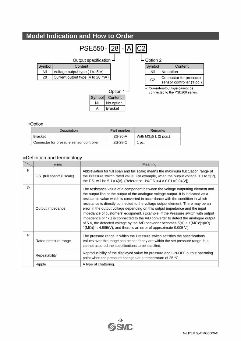
Model Indication and How to Order
○Option
Description Part number Remarks
Bracket ZS-30-A With M3x5 L (2 pcs.)
Connector for pressure sensor controller ZS-28-C 1 pc.
■Definition and terminology
Terms Meaning
F
F.S. (full span/full scale)
Abbreviation for full span and full scale; means the maximum fluctuation range of
the Pressure switch rated value. For example, when the output voltage is 1 to 5[V],
the F.S. will be 5-1 = 4[V]. (Reference: 1%F.S. = 4 × 0.01 = 0.04[V])
O
Output impedance
The resistance value of a component between the voltage outputting element and
the output line at the output of the analogue voltage output. It is indicated as a
resistance value which is converted in accordance with the condition in which
resistance is directly connected to the voltage output element. There may be an
error in the output voltage depending on this output impedance and the input
impedance of customers' equipment. (Example: If the Pressure switch with output
impedance of 1kΩ is connected to the A/D converter to detect the analogue output
of 5 V, the detected voltage by the A/D converter becomes 5(V) × 1(MΩ)/(1(kΩ) +
1(MΩ)) ≒ 4.995(V), and there is an error of approximate 0.005 V.)
R
Rated pressure range
The pressure range in which the Pressure switch satisfies the specifications.
Values over this range can be set if they are within the set pressure range, but
cannot assured the specifications to be satisfied.
Repeatability Reproducibility of the displayed value for pressure and ON-OFF output operating
point when the pressure changes at a temperature of 25 oC.
Ripple A type of chattering.

-9-
No.PS※※-OMG0009-C
Mounting and Installation
■Piping ○Piping connections Cut the air tube perpendicularly.
Grasp the air tube and insert it to resin firmly by 8 mm or more from the end the resin piping. The pulling
force necessary for the piping inserted by 8 mm or more is approximate 25N.
Insert the air tube for low pressure to Lo piping and the air tube for high pressure to Hi piping.
■Wiring ○Attaching the connector to the lead wire Sensor wire is stripped as shown in the right figure.
Do not cut the insulation.
The core of the corresponding color shown in the
following table is put into the pin of the number stamped
on the connector for sensor connection to the back.
Pin No. Wire color
PSE55□ PSE55□-28
1 Brown (DC+) Brown (LINE(+))
2 NC NC
3 Blue (DC-) NC
4 Black (IN: 1 to 5 V) Blue (LINE(-))
It checks that the above-mentioned preparation work has been performed correctly, and A part shown in
right figure is pushed by hand and makes temporary connection.
A part center is straightly pushed in by tools, such as pliers.
Re-use cannot be performed once it connects the connector for sensor connection completely. When you
fail in the connection mistake of a core and a pin, or the plug of wire, please use the new connector for
sensor connection.
When connecting the connector to PSE300 series, please use the connector for sensor lead wire
(ZS-28-C) or as below.
Maker Model No.
Sumitomo 3M 37104-3101-000FL
Tyco Electronics 1-1473562-4
OMRON XN2A-1430
Please contact with each connector maker about catalogue.
-10-
No.PS※※-OMG0009-C
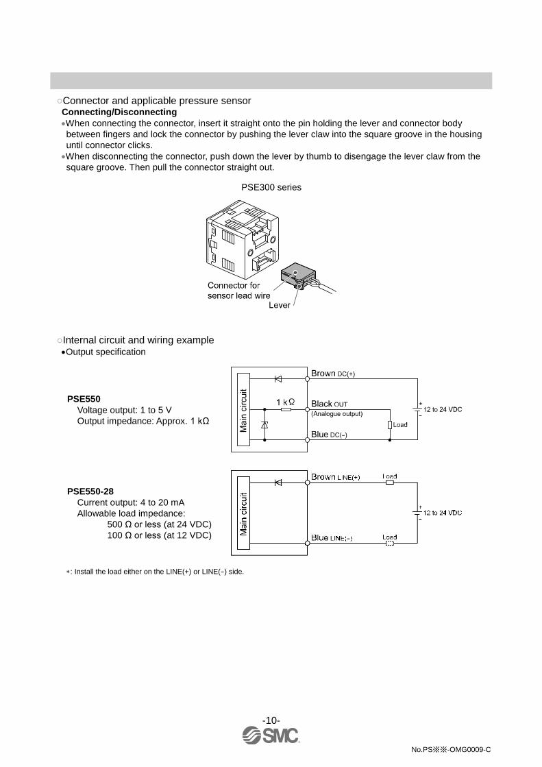
○Connector and applicable pressure sensor Connecting/Disconnecting When connecting the connector, insert it straight onto the pin holding the lever and connector body
between fingers and lock the connector by pushing the lever claw into the square groove in the housing
until connector clicks.
When disconnecting the connector, push down the lever by thumb to disengage the lever claw from the
square groove. Then pull the connector straight out.
PSE300 series
○Internal circuit and wiring example Output specification
PSE550
Voltage output: 1 to 5 V
Output impedance: Approx. 1 kΩ
PSE550-28
Current output: 4 to 20 mA
Allowable load impedance:
500 Ω or less (at 24 VDC)
100 Ω or less (at 12 VDC)
: Install the load either on the LINE(+) or LINE(-) side.
-11-
No.PS※※-OMG0009-C
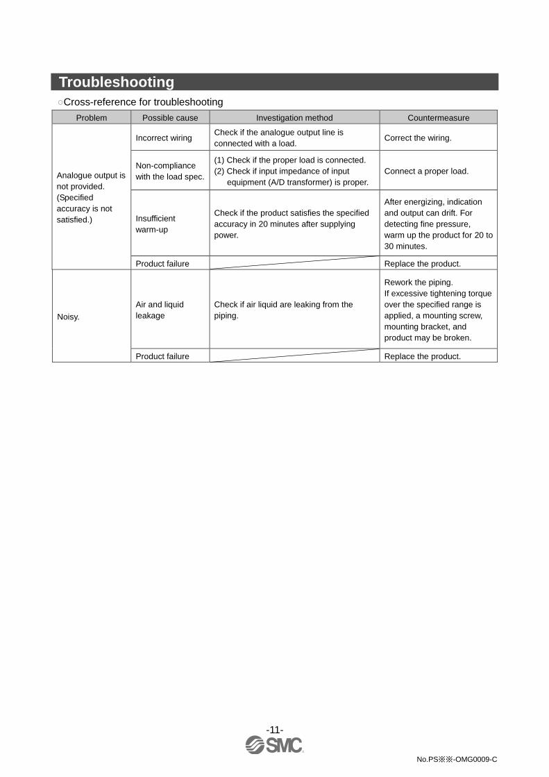
Troubleshooting
○Cross-reference for troubleshooting
Problem Possible cause Investigation method Countermeasure
Analogue output is
not provided.
(Specified
accuracy is not
satisfied.)
Incorrect wiring Check if the analogue output line is
connected with a load. Correct the wiring.
Non-compliance
with the load spec.
(1) Check if the proper load is connected.
(2) Check if input impedance of input
equipment (A/D transformer) is proper.
Connect a proper load.
Insufficient
warm-up
Check if the product satisfies the specified
accuracy in 20 minutes after supplying
power.
After energizing, indication
and output can drift. For
detecting fine pressure,
warm up the product for 20 to
30 minutes.
Product failure Replace the product.
Noisy.
Air and liquid
leakage
Check if air liquid are leaking from the
piping.
Rework the piping.
If excessive tightening torque
over the specified range is
applied, a mounting screw,
mounting bracket, and
product may be broken.
Product failure Replace the product.

-12-
No.PS※※-OMG0009-C
Specification
■Specifications
Model No. PSE550 PSE550-28
Rated differential pressure range 0 to 2 kPa
Operating pressure range -50 to 50 kPa
Extension analogue output range -0.2 to 0 kPa -
Withstand pressure 65 kPa
Applicable Air, inert gases and incombustible gases
Power supply voltage 12 to 24 VDC±10%, ripple (p-p) 10% or less (Protected against inverse connection)
Current consumption 15 mA or less
Output specification
Analogue output: 1 to 5 VDC
(with rated pressure range)
0.6 to 1 VDC
(with extension analogue
output range)
Output impedance: Approx. 1 kΩ
Analogue output: 4 to 20 mA
(within rated differential
pressure range)
Allowable load impedance:
500 Ω or less (at 24 VDC)
100 Ω or less (at 12 VDC)
Accuracy
(Ambient temperature at 25 oC)
±1%F.S. (with rated pressure range)
±3%F.S. (with extension analogue output range)
Linearity ±0.5%F.S.
Repeatability ±0.3%F.S.
Indication light Orange light is turned on. (When energized)
Environ
ment
Enclosure IP40
Ambient temperature
range Operation: 0 to 50 oC, Storage: -20 to 70 oC (No condensation or freezing)
Ambient humidity
range Operation, Storage: 35 to 85%RH (No condensation)
Withstand voltage 1000 VAC, 50/60 Hz, 1 minute, Between lead block and case
Insulation resistance 50 MΩ or more at 500 VDC Between lead block and case
Temperature characteristic ±3%F.S. (25 oC reference)
Port size ø4.8 (ø4.4 in the end) resin piping (Applicable to I.D. ø4 air tubing)
Wetted parts material Resin pipe: Nylon, Piston area of sensor: Silicon
Sensor cable
Oil proof heavy-duty vinyl cable (ellipse)
3 cores, 2.7x3.2, 3 m
Conductor area: 0.15 mm2
Insulator O.D.: 0.9 mm
Oil proof heavy-duty vinyl cable (ellipse)
2 cores, 2.7x3.2, 3 m
Conductor area: 0.15 mm2
Insulator O.D.: 0.9 mm
Mass With sensor cable 75 g
Without sensor cable 35 g
Standard CE, UL/CSA, RoHS
: Can detect differential pressure from 0 to 2 kPa within the range of –50 to 50 kPa.
It becomes the following specification overall when PSE300 and combining.
Setting pressure range For differential pressure range
Rated pressure range 0 to 2 kPa
Set resolution 0.01 kPa
Switch output Repeatability ±0.4%F.S.
Analogue
output
Linearity ±0.7%F.S.
Accuracy (Display value) ±1.5%F.S.
Accuracy (Operating temperature 25 oC) ±1.5%F.S. ±1 digit
Temperature characteristic ±3.5%F.S. (25 oC standard)

-13-
No.PS※※-OMG0009-C
○Analogue output
PSE550 PSE550-28

-14-
No.PS※※-OMG0009-C
■Dimensions ○Body dimensions
○Mounting by bracket

No.PS※※-OMG0009-C
Revision history
A: Complete revision.
B: Limited warranty and Disclaimer and
measurement laws are added.
C: Modified errors in text. [July 2016]
4-14-1, Sotokanda, Chiyoda-ku, Tokyo 101-0021 JAPAN Tel: + 81 3 5207 8249 Fax: +81 3 5298 5362 URL http://www.smcworld.com Note: Specifications are subject to change without prior notice and any obligation on the part of the manufacturer. © 2010-2016 SMC Corporation All Rights Reserved


