+ All Categories
Home > Documents > Sway Bar Installation Instructions Covers Part #5998 - … Sway Bar Installation 1. Locate the rear...

Sway Bar Installation Instructions Covers Part #5998 - … Sway Bar Installation 1. Locate the rear...

Date post: 05-Feb-2018
Category:
Upload: lytuong
View: 214 times
Download: 0 times
Share this document with a friend
2
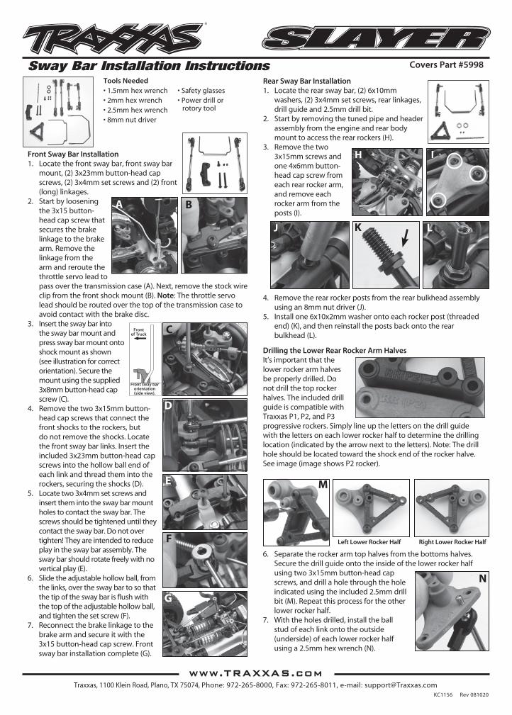
Rear Sway Bar Installation 1. Locate the rear sway bar, (2) 6x10mm washers, (2) 3x4mm set screws, rear linkages, drill guide and 2.5mm drill bit. 2. Start by removing the tuned pipe and header assembly from the engine and rear body mount to access the rear rockers (H). 3. Remove the two 3x15mm screws and one 4x6mm button- head cap screw from each rear rocker arm, and remove each rocker arm from the posts (I). 4. Remove the rear rocker posts from the rear bulkhead assembly using an 8mm nut driver (J). 5. Install one 6x10x2mm washer onto each rocker post (threaded end) (K), and then reinstall the posts back onto the rear bulkhead (L). Drilling the Lower Rear Rocker Arm Halves It’s important that the lower rocker arm halves be properly drilled. Do not drill the top rocker halves. The included drill guide is compatible with Traxxas P1, P2, and P3 progressive rockers. Simply line up the letters on the drill guide with the letters on each lower rocker half to determine the drilling location (indicated by the arrow next to the letters). Note: The drill hole should be located toward the shock end of the rocker halve. See image (image shows P2 rocker). 6. Separate the rocker arm top halves from the bottoms halves. Secure the drill guide onto the inside of the lower rocker half using two 3x15mm button-head cap screws, and drill a hole through the hole indicated using the included 2.5mm drill bit (M). Repeat this process for the other lower rocker half. 7. With the holes drilled, install the ball stud of each link onto the outside (underside) of each lower rocker half using a 2.5mm hex wrench (N). KC1156 Rev 081020 Covers Part #5998 Sway Bar Installation Instructions Tools Needed • 1.5mm hex wrench • 2mm hex wrench • 2.5mm hex wrench • 8mm nut driver • Safety glasses • Power drill or rotory tool Front Sway Bar Installation 1. Locate the front sway bar, front sway bar mount, (2) 3x23mm button-head cap screws, (2) 3x4mm set screws and (2) front (long) linkages. 2. Start by loosening the 3x15 button- head cap screw that secures the brake linkage to the brake arm. Remove the linkage from the arm and reroute the throttle servo lead to pass over the transmission case (A). Next, remove the stock wire clip from the front shock mount (B). Note: The throttle servo lead should be routed over the top of the transmission case to avoid contact with the brake disc. 3. Insert the sway bar into the sway bar mount and press sway bar mount onto shock mount as shown (see illustration for correct orientation). Secure the mount using the supplied 3x8mm button-head cap screw (C). 4. Remove the two 3x15mm button- head cap screws that connect the front shocks to the rockers, but do not remove the shocks. Locate the front sway bar links. Insert the included 3x23mm button-head cap screws into the hollow ball end of each link and thread them into the rockers, securing the shocks (D). 5. Locate two 3x4mm set screws and insert them into the sway bar mount holes to contact the sway bar. The screws should be tightened until they contact the sway bar. Do not over tighten! They are intended to reduce play in the sway bar assembly. The sway bar should rotate freely with no vertical play (E). 6. Slide the adjustable hollow ball, from the links, over the sway bar to so that the tip of the sway bar is flush with the top of the adjustable hollow ball, and tighten the set screw (F). 7. Reconnect the brake linkage to the brake arm and secure it with the 3x15 button-head cap screw. Front sway bar installation complete (G). B L A K M D E G www.TRAXXAS.com Traxxas, 1100 Klein Road, Plano, TX 75074, Phone: 972-265-8000, Fax: 972-265-8011, e-mail: [email protected] C H J I F N Front of Truck Front sway bar orientation (side view). Left Lower Rocker Half Right Lower Rocker Half
Transcript

Rear Sway Bar Installation1. Locatetherearswaybar,(2)6x10mm

washers,(2)3x4mmsetscrews,rearlinkages,drillguideand2.5mmdrillbit.

2. Startbyremovingthetunedpipeandheaderassemblyfromtheengineandrearbodymounttoaccesstherearrockers(H).

3. Removethetwo3x15mmscrewsandone4x6mmbutton-headcapscrewfromeachrearrockerarm,andremoveeachrockerarmfromtheposts(I).

4. Removetherearrockerpostsfromtherearbulkheadassemblyusingan8mmnutdriver(J).

5. Installone6x10x2mmwasherontoeachrockerpost(threadedend)(K),andthenreinstallthepostsbackontotherearbulkhead(L).

Drilling the Lower Rear Rocker Arm HalvesIt’simportantthatthelowerrockerarmhalvesbeproperlydrilled.Donotdrillthetoprockerhalves.TheincludeddrillguideiscompatiblewithTraxxasP1,P2,andP3progressiverockers.Simplylineupthelettersonthedrillguidewiththelettersoneachlowerrockerhalftodeterminethedrillinglocation(indicatedbythearrownexttotheletters).Note:Thedrillholeshouldbelocatedtowardtheshockendoftherockerhalve.Seeimage(imageshowsP2rocker).

6. Separatetherockerarmtophalvesfromthebottomshalves.Securethedrillguideontotheinsideofthelowerrockerhalfusingtwo3x15mmbutton-headcapscrews,anddrillaholethroughtheholeindicatedusingtheincluded2.5mmdrillbit(M).Repeatthisprocessfortheotherlowerrockerhalf.

7. Withtheholesdrilled,installtheballstudofeachlinkontotheoutside(underside)ofeachlowerrockerhalfusinga2.5mmhexwrench(N).

KC1156Rev081020

Covers Part #5998Sway Bar Installation InstructionsTools Needed•1.5mmhexwrench•2mmhexwrench•2.5mmhexwrench•8mmnutdriver

•Safetyglasses•Powerdrillor

rotorytool

Front Sway Bar Installation1. Locatethefrontswaybar,frontswaybar

mount,(2)3x23mmbutton-headcapscrews,(2)3x4mmsetscrewsand(2)front(long)linkages.

2. Startbylooseningthe3x15button-headcapscrewthatsecuresthebrakelinkagetothebrakearm.Removethelinkagefromthearmandreroutethethrottleservoleadtopassoverthetransmissioncase(A).Next,removethestockwireclipfromthefrontshockmount(B).Note:Thethrottleservoleadshouldberoutedoverthetopofthetransmissioncasetoavoidcontactwiththebrakedisc.

3. Inserttheswaybarintotheswaybarmountandpressswaybarmountontoshockmountasshown(seeillustrationforcorrectorientation).Securethemountusingthesupplied3x8mmbutton-headcapscrew(C).

4. Removethetwo3x15mmbutton-headcapscrewsthatconnectthefrontshockstotherockers,butdonotremovetheshocks.Locatethefrontswaybarlinks.Inserttheincluded3x23mmbutton-headcapscrewsintothehollowballendofeachlinkandthreadthemintotherockers,securingtheshocks(D).

5. Locatetwo3x4mmsetscrewsandinsertthemintotheswaybarmountholestocontacttheswaybar.Thescrewsshouldbetighteneduntiltheycontacttheswaybar.Donotovertighten!Theyareintendedtoreduceplayintheswaybarassembly.Theswaybarshouldrotatefreelywithnoverticalplay(E).

6. Slidetheadjustablehollowball,fromthelinks,overtheswaybartosothatthetipoftheswaybarisflushwiththetopoftheadjustablehollowball,andtightenthesetscrew(F).

7. Reconnectthebrakelinkagetothebrakearmandsecureitwiththe3x15button-headcapscrew.Frontswaybarinstallationcomplete(G).

B

L

A

K

M

D

E

G

www.TRAXXAS.comTraxxas,1100KleinRoad,Plano,TX75074,Phone:972-265-8000,Fax:972-265-8011,e-mail:[email protected]

C

H

J

I

F

N

Frontof Truck

Front sway bar orientation (side view).

Left Lower Rocker Half Right Lower Rocker Half

081020_KC1156_5998SlayerSway.indd 1 10/20/08 5:00:44 PM

www.TRAXXAS.comTraxxas,1100KleinRoad,Plano,TX75074,Phone:972-265-8000,Fax:972-265-8011,e-mail:[email protected]

8. Connectthetoprockerhalveswiththeappropriatelowershalvesandreinstallthemontotherockerposts.Securethemwiththesame3x15mmand4x6mmbutton-headcapscrews(O).

9. Locatethelowertwo3x20mmbutton-headcapcrewsontherearbumperofthetruck.Loosenthetwoscrewsuntiltheyreleasefromthechassis,butdonotremovethem(P).

10.Pullthelowerbumpersectionawayfromthechassis,andtheninserttherearswaybarintothemoldedswaybargrooveofthebumper.Theblueswaybarsleeveshouldbecenteredintothegroove(Q).Tightenthebumperbackontothechassis.Note:Makesurethatthereartoelinksaresecuredbythescrews.

11.Locatetwo3x4mmsetscrewsandinsertthemintotherearswaybarmountholestocontacttheswaybar(sameasthefrontswaybar)(R).Threadthescrewsinuntiltheycontacttheswaybarsleeve.Theswaybarshouldpivotfreely.

12.Attachtheadjustablehollowballsfromthelinksontotherearswaybarandtightenthesetscrewsinthedesiredposition.Adjustment note:Eachlinkmustclearboththechassisandtherockerarmsthroughtheentirerangeofthesuspensionstroke(S).

13.Reinstallthetunedpipeandheaderassembly,andadjusttheswaybarsforoverallsmoothoperation.Rearswaybarinstallationcomplete(T).

Settings and Adjustment Notes• Adjustthefrontswaybarlinkssothe

swaybarsarealmostverticalwhilethetruckisonthegroundandthesuspensionisatrest(normalrideheight).Thisallowsequalswaybartravelinbothloadedandunloadedsuspensionconditions.Alwaysadjusttheleftandrightswaybarlinksequallytopreventsuspensiontweak.

• Theadjustablehollowballscanberaisedorloweredclosertoorfurtherfromtheswaybarmount(pivotpoint).Closertothepivotpointresultsinastiffersettingandfurtherfromthepivotpointresultsinasoftersetting.

For smooth surfaces with high traction:• StifferresponsesettingsFor rough surfaces with low traction:• SofterresponsesettingsTo reduce understeer (pushing in corners):• Softenfrontsetting• StiffenrearsettingTo reduce oversteer (loose in corners):• Stiffenfrontsetting• Softenrearsetting

Softer

Stiffer

27433x4 GS

27433x4 GS

27433x4 GS

27433x4 GS

27433x4 GS

27433x4 GS

25813x23 BCS

25813x23 BCS

25913x23 BCS

25913x23 BCS

27433x4 GS

27433x4 GS

27433x4 GS

27433x4 GS

25763x8 BCS

25763x8 BCS

25803x20 BCS

25803x20 BCS

25803x20 BCS

27433x4 GS

27433x4 GS 2743

3x4 GS

54966x10x2 MW

54966x10x2 MW

54966x10x2 MW

39394x6 BCS

39394x6 BCS

39394x6 BCS

39394x6 BCS

39394x6 BCS

39394x6 BCS

39394x6 BCS

39394x6 BCS

53545354X

53545354X

27433x4 GS

27433x4 GS

5495

5495

5496

5496

54985496

59985496

54985496

59985496

5496

5496

5495

5495

5497

5497

5497

5497

5496

Front Sway Bar AssemblyRear Sway Bar Assembly

5495 Linkage,frontswaybar(Revo/Slayer)(3x70mmturnbuckle)(2)(assembledwithrodends,hollowballsandballstud).................................................. 12.00

5496 Swaybarmounts(front&rear)(Revo/Slayer)/swaybarwires(front&rear)(4)/drillguide/spacers.......... 10.00

5497 Linkage,rearswaybar(Revo/Slayer)(3x50mmturnbuckle)(2)(assembledwithrodends,hollowballsandballstud).................................................. 12.00

5998 Swaybarkit,Slayer(frontandrear)(includes frontandrearswaybarsandadjustablelinkage)...... 30.00

O

P

Q

S

R

T

If you have questions or need technical assistance, call Traxxas at

1-888-TRAXXAS (1-888-872-9927)(U.S.residentsonly)

081020_KC1156_5998SlayerSway.indd 2 10/20/08 5:00:47 PM


Recommended