10.003 Chemistry 1D Designette Page 1 of 16 Design and Fabrication of Microfluidic Device for Lab-on-a-Chip Chemistry Microfluidics, the manipulation of fluid streams in micro-scale dimensions, is of growing technological interest because of its diverse applications, including medical diagnostics and environmental monitoring of contaminants. Microfluidic devices are becoming increasingly important because (i) they require only small reaction and hence reagent volumes (nano- to picoliters) and (ii) their narrow channel diameters facilitate efficient analytical systems. For example, microfluidic channels have been used to deliver samples for DNA manipulation and protein analysis; such samples usually come only in small volumes due to their high cost. Furthermore, microfluidic networks built on lap-on-chip devices are considered to be high-throughput, miniaturized, mobile laboratories. A key feature of solutions in a microfluidic device that is different from solutions in bulk analog is that the fluid flow within microfluidic channels is laminar. This means that parallel fluid streams in the same channel will flow independently of each other with little or no mixing at the interface. Practically, however, diffusion across adjacent streams allows reagents from each stream to react. A microfluidic channel therefore, provides a useful platform for performing confined chemical reactions and demonstrating the dynamics of fluid flow in small volumes. In this 3-session laboratory exercise, we are going to learn: (1) how chemistry knowledge is used to design materials with desirable physical and chemical properties; (2) how different materials are used in a design sequence to prototype a device for certain function: in this case, a microfluidic device with Y-shaped channel for interfacing two fluids; (3) to visualize chemical reactions under laminar flow in the microfluidic device and compare the results to those in bulk solutions. Background Let’s have a brief introduction of Polymer Chemistry before going into the details of the laboratory process. A rational design and synthesis procedure could help us tailor the structure and architecture of a polymer which would impact its various physical (e.g., flexibility) and chemical (e.g., surface adhesion) properties. Polymers are macromolecules formed by linking large numbers of much smaller molecules called monomers. These chemicals have a large molecular weight and many repeating units or chemical structures. Polymerization refers to the reactions by which the monomers are combined. ―Curing‖ is another common terminology used to describe polymerization or the ―hardening‖ process. Two types of classifications can be used to group the polymers. One classification is based on polymer structure: condensation and
Transcript
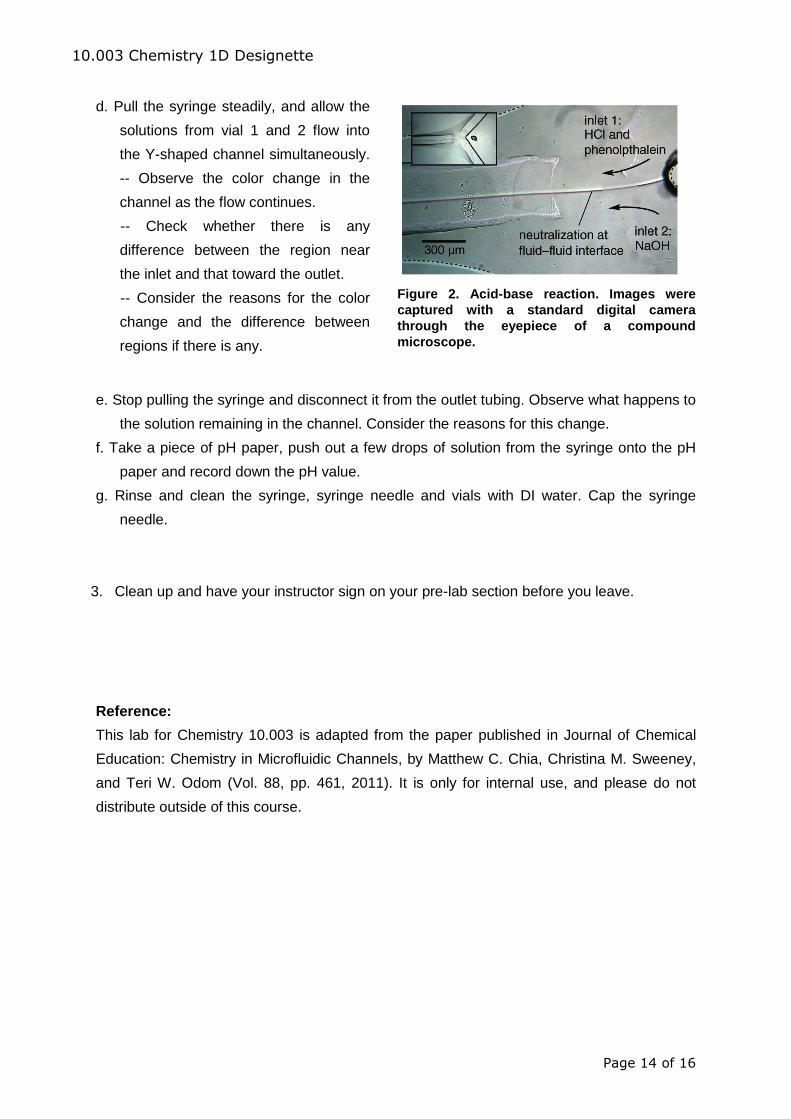
10.003 Chemistry 1D Designette
Page 1 of 16
Design and Fabrication of Microfluidic Device for Lab-on-a-Chip Chemistry
Microfluidics, the manipulation of fluid streams in micro-scale dimensions, is of growing
technological interest because of its diverse applications, including medical diagnostics and
environmental monitoring of contaminants. Microfluidic devices are becoming increasingly
important because (i) they require only small reaction and hence reagent volumes (nano- to
picoliters) and (ii) their narrow channel diameters facilitate efficient analytical systems. For
example, microfluidic channels have been used to deliver samples for DNA manipulation
and protein analysis; such samples usually come only in small volumes due to their high
cost. Furthermore, microfluidic networks built on lap-on-chip devices are considered to be
high-throughput, miniaturized, mobile laboratories.
A key feature of solutions in a microfluidic device that is different from solutions in bulk
analog is that the fluid flow within microfluidic channels is laminar. This means that parallel
fluid streams in the same channel will flow independently of each other with little or no
mixing at the interface. Practically, however, diffusion across adjacent streams allows
reagents from each stream to react. A microfluidic channel therefore, provides a useful
platform for performing confined chemical reactions and demonstrating the dynamics of fluid
flow in small volumes.
In this 3-session laboratory exercise, we are going to learn:
(1) how chemistry knowledge is used to design materials with desirable physical and
chemical properties;
(2) how different materials are used in a design sequence to prototype a device for certain
function: in this case, a microfluidic device with Y-shaped channel for interfacing two
fluids;
(3) to visualize chemical reactions under laminar flow in the microfluidic device and compare
the results to those in bulk solutions.
Background
Let’s have a brief introduction of Polymer Chemistry before going into the details of the
laboratory process. A rational design and synthesis procedure could help us tailor the
structure and architecture of a polymer which would impact its various physical (e.g.,
flexibility) and chemical (e.g., surface adhesion) properties.
Polymers are macromolecules formed by linking large numbers of much smaller
molecules called monomers. These chemicals have a large molecular weight and many
repeating units or chemical structures. Polymerization refers to the reactions by which the
monomers are combined. ―Curing‖ is another common terminology used to describe
polymerization or the ―hardening‖ process. Two types of classifications can be used to
group the polymers. One classification is based on polymer structure: condensation and
10.003 Chemistry 1D Designette
Page 2 of 16
addition. The other classification is based on polymerization mechanism: step and chain
polymerizations. Generally, most condensation polymers are produced by step
polymerizations and most addition polymers are produced by chain polymerizations. The
most important difference in chain and step polymerizations is in the identities of the species
that can react with each other. As the name suggests, step polymerizations proceed by the
stepwise reaction between the functional groups of reactants as in reactions, for example
COOH with NH2, or COOH with OH. In chain polymerization, an initiator is used to produce
an initiator species R* with a reactive center which may be a free radical, cation, or anion.
Chain polymerization occurs by the propagation of the reactive center by the successive
additions of large numbers of monomer molecules in a chain reaction. (George Odian,
Principles of Polymerization, Wiley-Interscience, 2004)
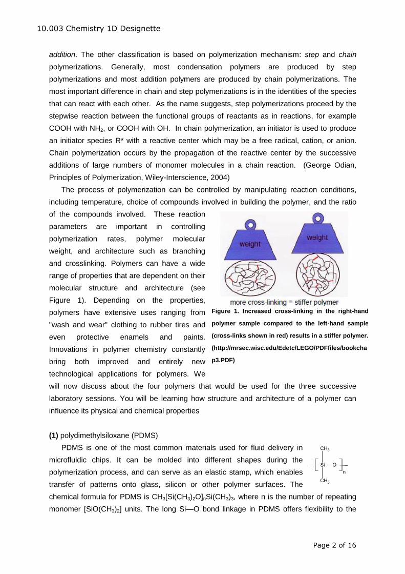
The process of polymerization can be controlled by manipulating reaction conditions,
including temperature, choice of compounds involved in building the polymer, and the ratio
of the compounds involved. These reaction
parameters are important in controlling
polymerization rates, polymer molecular
weight, and architecture such as branching
and crosslinking. Polymers can have a wide
range of properties that are dependent on their
molecular structure and architecture (see
Figure 1). Depending on the properties,
polymers have extensive uses ranging from
"wash and wear" clothing to rubber tires and
even protective enamels and paints.
Innovations in polymer chemistry constantly
bring both improved and entirely new
technological applications for polymers. We
will now discuss about the four polymers that would be used for the three successive
laboratory sessions. You will be learning how structure and architecture of a polymer can
influence its physical and chemical properties
(1) polydimethylsiloxane (PDMS)
PDMS is one of the most common materials used for fluid delivery in
microfluidic chips. It can be molded into different shapes during the
polymerization process, and can serve as an elastic stamp, which enables
transfer of patterns onto glass, silicon or other polymer surfaces. The
chemical formula for PDMS is CH3[Si(CH3)2O]nSi(CH3)3, where n is the number of repeating
monomer [SiO(CH3)2] units. The long Si—O bond linkage in PDMS offers flexibility to the
Figure 1. Increased cross-linking in the right-hand
polymer sample compared to the left-hand sample
(cross-links shown in red) results in a stiffer polymer.