PDS2-H Weather Compensator with Modbus Communication
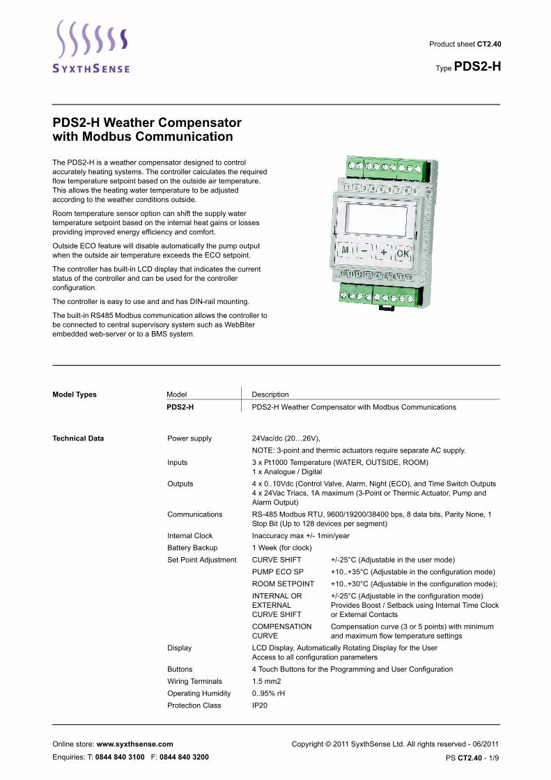
The PDS2-H is a weather compensator designed to control accurately heating systems. The controller calculates the required flow temperature setpoint based on the outside air temperature. This allows the heating water temperature to be adjusted according to the weather conditions outside.
Room temperature sensor option can shift the supply water temperature setpoint based on the internal heat gains or losses providing improved energy efficiency and comfort.
Outside ECO feature will disable automatically the pump output when the outside air temperature exceeds the ECO setpoint.
The controller has built-in LCD display that indicates the current status of the controller and can be used for the controller configuration.
The controller is easy to use and and has DIN-rail mounting.
The built-in RS485 Modbus communication allows the controller to be connected to central supervisory system such as WebBiter embedded web-server or to a BMS system.
Product sheet CT2.40
Type PDS2-H
Model Types Model Description
PDS2-H PDS2-H Weather Compensator with Modbus Communications
Technical Data Power supply 24Vac/dc (20…26V),
NOTE: 3-point and thermic actuators require separate AC supply.
Inputs 3 x Pt1000 Temperature (WATER, OUTSIDE, ROOM)1 x Analogue / Digital
Outputs 4 x 0..10Vdc (Control Valve, Alarm, Night (ECO), and Time Switch Outputs4 x 24Vac Triacs, 1A maximum (3-Point or Thermic Actuator, Pump and Alarm Output)
Communications RS-485 Modbus RTU, 9600/19200/38400 bps, 8 data bits, Parity None, 1 Stop Bit (Up to 128 devices per segment)
Internal Clock Inaccuracy max +/- 1min/year
Battery Backup 1 Week (for clock)
Set Point Adjustment CURVE SHIFT +/-25°C (Adjustable in the user mode)
PUMP ECO SP +10..+35°C (Adjustable in the configuration mode)
ROOM SETPOINT +10..+30°C (Adjustable in the configuration mode);
INTERNAL OR EXTERNALCURVE SHIFT
+/-25°C (Adjustable in the configuration mode)Provides Boost / Setback using Internal Time Clock or External Contacts
COMPENSATION CURVE
Compensation curve (3 or 5 points) with minimum and maximum flow temperature settings
Display LCD Display, Automatically Rotating Display for the UserAccess to all configuration parameters
Buttons 4 Touch Buttons for the Programming and User Configuration
Wiring Terminals 1.5 mm2
Operating Humidity 0..95% rH
Protection Class IP20
SyxthSense Ltd
PS CT2.40 - 2/9
APPLICATION PROFILE PDS2 controllers have two application profiles for different applications: PDS2-V and PDS2-H. PDS 2-V application profile is selected as a default. To change the application profile to PDS2-H follow the following instructions.
The application profile can be selected when the supply voltage is connected to the device.
1. Press the ”+” and ”-” buttons simultaneously for five seconds.
The device version shows on the display for five seconds.
1.1VER
2. Press the OK button when ”APPL” is shown on the display.
”APPL” text starts to flash.
APPL=VENT
WARNING: The device returns to user mode if the buttons are not pushed during 10 seconds.
3. Select the wanted application by pushing the "+" and "-" buttons.
4. Push the OK button.
The confirmation question appears on the display.
APPLSURE?
5. Press the OK button to accept the application selection.
NOTE: You can return to previous display without accepting the selection by pressing the M button.
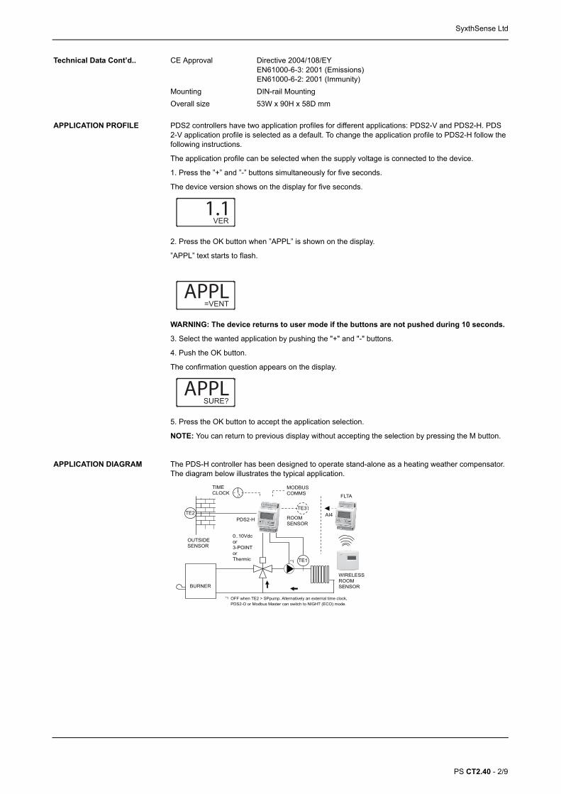
APPLICATION DIAGRAM The PDS-H controller has been designed to operate stand-alone as a heating weather compensator. The diagram below illustrates the typical application.
TE2
BURNER
PDS2-H
TE1
TE3
ROOMSENSOR
*1
*1 OFF when TE2 > SPpump. Alternatively an external time clock,
TIMECLOCK
0..10Vdcor3-POINTorThermic
MODBUSCOMMS
OUTSIDESENSOR
PDS2-O or Modbus Master can switch to NIGHT (ECO) mode.
FLTA
WIRELESSROOMSENSOR
AI4
Technical Data Cont’d.. CE Approval Directive 2004/108/EYEN61000-6-3: 2001 (Emissions)EN61000-6-2: 2001 (Immunity)
Mounting DIN-rail Mounting
Overall size 53W x 90H x 58D mm
SyxthSense Ltd
PS CT2.40 - 3/9
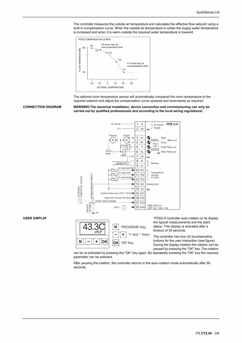
The controller measures the outside air temperature and calculates the effective flow setpoint using a built-in compensation curve. When the outside air temperature is colder the supply water temperature is increased and when it is warm outside the required water temperature is lowered.
FLO
W T
EM
PE
RAT
UR
E
OUTSIDE TEMPERATURE
20
-20
80
-10 0 10 20 30
P5
P4P3
P2
P1
P5 works also asmax temperature limit
P1 works also asmin temperature limit
PDS2 COMPENSATION CURVE
The optional room temperature sensor will automatically compared the room temperature to the required setpoint and adjust the compensation curve upwards and downwards as required.
PDS 2-HGo
G12
3456789
12
14
Go
1011
13Go
A+
B-
16
18
15
17
A1
B1
AL
P
TE2
TE3
AI4
TE1
AO1
AO2
AO3
AO4
Supply24 Vac/dc
Modbus
TemperaturesensorsPt 1000
Analog Input
Control Valve out 0-10V / 10-0V
0V
Modbus
Fuse1,5A
Open
Pump Relay out
CloseMotor out
Alarm Relay out
24 Vac/dc
0 V
Pt 1000 WATER
Thermal
24VacFeed
M
3-Point
M
Pt 1000 OUT
Pt 1000 ROOM
0V
Alarm (0V normal 10V fault )
OUT=
SETB
ACK/
BOO
ST/N
IGH
T
TIME SWITCH ”OFF”=0V ”ON”= 10V
NIGHT (ECO) MODE
BOO
ST/
SETA
BCK
Pump
Alarm
EXTE
RN
ALC
ON
TAC
TS /
CLO
CK
0V
CONNECTION DIAGRAM WARNING:The electrical installation, device connection and commissioning can only be carried out by qualified professionals and according to the local wiring regulations!
USER DISPLAY
M 'PROGRAM' Key
'+' and '-' Keys
'OK' KeyM OK
43.3C
OK
effSP
PDS2-H controller auto-rotates on its display the typical measurements and the plant status. This display is activated after a timeout of 30 seconds.
The controller has four (4) touchsensitive buttons for the user interaction (see figure). During the display rotation the rotation can be paused by pressing the "OK" key. The rotation
can be re-activated by pressing the "OK" key again. By repeatedly pressing the "OK" key the required parameter can be selected.
After pausing the rotation, the controller returns to the auto-rotation mode automatically after 60 seconds.
SyxthSense Ltd
PS CT2.40 - 4/9
The display rotates between the following readings:
Optional displays provide additional information in abnormal conditions e.g Flow Temperature High Limit is active or a sensor has been disconnected.
USER SETTINGS By pressing the "PROGRAM’ key the user can adjust the heating compensation curve upwards or downwards (+/-25°C).
• Press ’PROGRAM’ key to display the current CURVE SHIFT setting.• Press ’+’ and ’-’ keys to shift the compensation curve vertically upwards or downwards.• Once the required setting is found press ’OK’ to accept the new setting. The controller returns to
the normal user display.
5.0CSP 43C
Curve ShiftSetting (+ or -)
Effective CalculatedFlow SetpointNote: The effective calculated setpointis automatically updated as and whenthe curve shift setting is changed.
FLO
W T
EMPE
RAT
UR
E
OUTSIDE TEMPERATURE
20
-20
80
-10 0 10 20 30
Curve ShiftParameter(+ or -)
PDS2 COMPENSATION CURVEMax FlowTemperature
Min FlowTemperature
M
M OK
CurCURVE
OK
To enter programming mode, press the following
OK
The 'CURVE' menu selectionis displayed on the screen.
Press 'OK' to enter to 'CURVE'(Compensation Curve) menu.
PROGRAMMING MODE The controller is operational without need for any programming. The controller expects to see flow and outside air temperature sensors. If a room temperature sensor is connected, this needs to be enabled in the input menu.
The controller compensation curve, 3-point actuator running time, the room setpoint etc. can be adjusted to meet the site requirement by entering to the programming mode.
To enter prgramming mode press the following keys ’+’, ’OK’, ’OK’ and ’M’.
SyxthSense Ltd
PS CT2.40 - 5/9
MENU STRUCTURE
ROOM RESET CONTROL PDS2-H controller has room reset control feature (if AI3 room sensor input has been enabled). This function will automatically adjust the water flow temperature according to the space conditions. To activate this function connect TEHR-PT1000 sensor or wireless room sensor via FLTA receiver to the PDS2-controller input AI3 (terminal 12).
CURCURVE
Point P1 of the compensationcurve.
TOP LEVEL MENU
CONCONTR
INPINPUT
CL0SET
Compensation Curve Menu
Control ParametersMenu
Measurement Input Menu
TIME Set Menu
Press 'OK' toenter 20.0C
P1 20C
Outside TemperaturePress 'M' and '+' or '-' to adjust, 'OK' to accept.
Required (Minimum) Flow Setpoint. Press '+' or '-' to adjust.
‘OK'
35.0CP2 15C
Point P2
80.0CP5 0C
Point P5
Required (Maximum) Flow Setpoint.
Press '+' or '-' to adjust.
Press 'OK' to continue
Pre
ss 'M
'
ProportionalBand [1..200]
Press 'OK' 50.0XP °C
Control Mode[P/PI]
=PISEL
1000Tint s
ON 23-P
[1=Thermic Actuator,2=3-Point Actuator]
180Tmot s
Actuator RunningTime [30..300s]
AO1=DIR
AO1 Operation[DIR = direct,REV = reverse]
OnPUMP
Pump Output[ON =Enabled, OFF=Disabled]
1MOD=
Modbus Address[1..247]
Pre
ss 'M
'
Integral ActionTime [50..5000s]
9.6kBaud
Modbus BaudRate [9.6/19.2/38.4]
'OK' 'OK' 'OK' 'OK'
'OK'
Pre
ss 'M
'
A1 1WATER
TE1 Settings
50FLT %
0.0CCAL
A1 2OUT
TE2 Settings
20.0CPU_SP
A1 3ROOM
TE3 Settings
OFFSEL
21.0CROOM°C
4RATIO
0.0CCAL
AO1 Output inCase of SensorFault [0..100]
Sensor Calibration[-2..+2]
Sensor Calibration[-2..+2]
Outside Eco Setpoint for Pump (pump off when TE2 > PU-SP)
Room Sensor[ON/OFF/AI4]
Room Setpoint[17..30]
Room InfluenceRatio [-6..+6]
'OK' 'OK' 'OK' 'OK'
'OK'
'OK'
'OK''OK'
‘OK'
50.0CP3 10C
Point P3‘OK'
65.0CP4 5C
Point P4‘OK'
'OK' 'OK''OK''OK'
0.0CCAL
Sensor Calibration[-2..+2]
'OK' 'OK' 'OK'
18.0CECOSP
Night ECO modeSetpoint [0..50]
'OK' 'OK'
XX.00TIME
Set Hours
12.XXTIME
Set Minutes
'OK'
X.00ON
“ON” Time Hours
'OK'
0.XXON
“ON” Time Minutes
'OK'
X.00OFF
“OFF” Time Hours
0.XXOFF
“OFF” Time Minutes
'OK'
'OK'
ECO/CUR
INTERNAL TIME controlselection. ECO (Night)or Curve Shift ModeDEFAULT = CURVE
MODE/SHIFT
'OK'
0.0CCurve Shift (+/-25°C)If CUR selected and AI4 MODE = OFF
CL1SET
Pre
ss 'M
'
'OK' 'OK'
A1 4INPUT
AI4 INPUT modeSelection (no adjustment)
ONMODE
If “ON”, PDS2 usesAI4 (term 13) to overridemode to ECO (Night) or to a Curve Shift Setting (Boost/Setback)
'OK' 'OK'
0.0CCurve Shift (+/-25°C)Activated when AI4 Mode = “ON”and AI4 (term 13) is connected to 0V
OFFMODE
If “OFF”, PDS2 usesInternal Clock to overridemode to ECO (Night) or to a Curve Shift Setting (Boost/Setback)
'OK'
A1 3ROOM
TE3 Settings
ONSEL
21.0CROOM°C
4RATIO
Enable Room Sensor[ON = EnabledAI4 = Wireless RoomSensor via AI4]
Room Setpoint[17..30]
Room InfluenceRatio [-6..+6].
E.g. with setting 4, one degreechange in the room temperatureequals four degrees change in theflow setpoint.
'OK' 'OK' 'OK'
SyxthSense Ltd
PS CT2.40 - 6/9
WIRELESS ROOM SENSOR If required, PDS2 controller can be connected to a wireless room sensor via FLTA receiver. The diagram below illustrates the configuration. The wireless room sensor is activated from the AI3 menu by selecting the AI4 option. The FLTA output is then connected to the AI4 input of the PDS2 controller (terminal 13).
PDS2-H
MODBUSCOMMS FLTA
WIRELESSROOMSENSOR
AI4
TEFL
AO1[0..10V]
A1 3ROOM
TE3 Settings
=AI4SEL
Room Sensor[AI4 = use inputAI4 for the room sensor)
'OK'
AI3 INPUT CONFIGURATION
If the AI4 voltage drops below 2V, the controller will consider this as a sensor fault. 2..10Vdc input signal equal to 0..50°C room temperature.
NOTE: If wireless room sensor is used with the PDS2-H, the external clock input (boost/setback) is disabled.
If the PDS2 controller AI4 external input mode is enabled (= internal clock disabled) the controller monitors the Analogue Input AI4 (Terminal 13) for override conditions.
A1 4INPUT
AI4 INPUT modeSelection
ONMODE
If “ON”, PDS2 usesAI4 (term 13) to overridemode to ECO (Night) or to a Curve Shift Setting (Boost/Setback)
'OK'
0.0CCurve Shift (+/-25°C)Activated when AI4 Mode = “ON”and AI4 (term 13) is connected to 0V
'OK'
NORMAL OPERATION
AI4 OPEN = The controller is in normal Operation (valve modulating, pump output running if enabled, and the effective setpoint calculated based on the outside air temperature).
SETBACK/BOOST
AI4 connected to 0V = The controller is in CURVE shift mode (boost or setback, +/-25°C).
When AI4 is connected to 0V the controller effective setpoint is shifted upwards (boost) or downwards (setback), otherwise the operation is as in the normal mode.
NIGHT (ECO) MODE
NOTE: This override is only active if the room sensor has been activated (AI3) and a room sensor has been installed.
AI4 connected to AO3 Terminal = Night Energy Saving (ECO) mode. The controller is OFF (valve closed and pump output off), unless the room temperature drops below night frost setpoint - see Night (ECO) Mode paragraph for further details.
NOTE: Night (ECO) Mode override is only available if a room sensor has been connected to input AI3 and the input has been enabled.
BOOST / SETBACK USING INTERNAL CLOCK (AI4 DISABLED)
If AI4 input mode has been disabled, the controller can be switched to Boost or Setback (shifting the compensation curve) using the internal time schedule, or the controller can be overdriven to Night ECO Mode by the internal time schedule.
SyxthSense Ltd
PS CT2.40 - 7/9
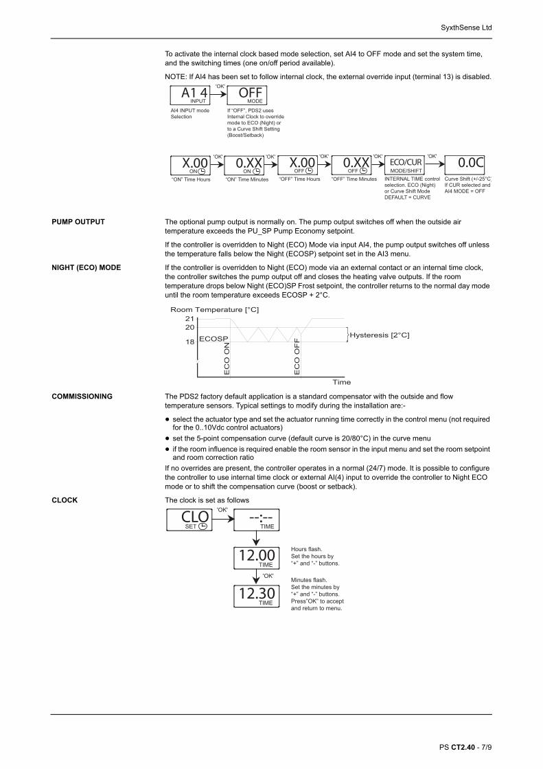
To activate the internal clock based mode selection, set AI4 to OFF mode and set the system time, and the switching times (one on/off period available).
NOTE: If AI4 has been set to follow internal clock, the external override input (terminal 13) is disabled.
A1 4INPUT
AI4 INPUT modeSelection
'OK'
OFFMODE
If “OFF”, PDS2 usesInternal Clock to overridemode to ECO (Night) or to a Curve Shift Setting (Boost/Setback)
X.00ON
“ON” Time Hours
'OK'
0.XXON
“ON” Time Minutes
'OK'
X.00OFF
“OFF” Time Hours
0.XXOFF
“OFF” Time Minutes
'OK' ECO/CUR
INTERNAL TIME controlselection. ECO (Night)or Curve Shift ModeDEFAULT = CURVE
MODE/SHIFT
'OK'
0.0CCurve Shift (+/-25°C)If CUR selected and AI4 MODE = OFF
'OK'
PUMP OUTPUT The optional pump output is normally on. The pump output switches off when the outside air temperature exceeds the PU_SP Pump Economy setpoint.
If the controller is overridden to Night (ECO) Mode via input AI4, the pump output switches off unless the temperature falls below the Night (ECOSP) setpoint set in the AI3 menu.
NIGHT (ECO) MODE If the controller is overridden to Night (ECO) mode via an external contact or an internal time clock, the controller switches the pump output off and closes the heating valve outputs. If the room temperature drops below Night (ECO)SP Frost setpoint, the controller returns to the normal day mode until the room temperature exceeds ECOSP + 2°C.
2120
18
Room Temperature [°C]
Time
EC
O O
N
EC
O O
FF
Hysteresis [2°C]ECOSP
COMMISSIONING The PDS2 factory default application is a standard compensator with the outside and flow temperature sensors. Typical settings to modify during the installation are:-
• select the actuator type and set the actuator running time correctly in the control menu (not required for the 0..10Vdc control actuators)
• set the 5-point compensation curve (default curve is 20/80°C) in the curve menu
• if the room influence is required enable the room sensor in the input menu and set the room setpoint and room correction ratio
If no overrides are present, the controller operates in a normal (24/7) mode. It is possible to configure the controller to use internal time clock or external AI(4) input to override the controller to Night ECO mode or to shift the compensation curve (boost or setback).
CLOSET
'OK'
--:--TIME
12.00TIME
'OK'
Hours flash.Set the hours by“+” and “-” buttons.
12.30TIME
Minutes flash.Set the minutes by“+” and “-” buttons.Press”OK” to accept and return to menu.
CLOCK The clock is set as follows
SyxthSense Ltd
PS CT2.40 - 8/9
The clock is disbaled by removing the time and replacing it by "--:--". By disabling the clock the time display is removed from the user display (rotating display) and the menu to set the switching times is hidden.
CLOSET
'OK'
12:30TIME
12.00TIME
Hours is reset to zero first.
After resetting the hours, the lines areset by pressing “-” key.Once completed press “OK.
SETTING SWITCHING TIMES Once the clock has been set, switching times menu is displayed on the controller configuration level. When the clock is activated (ON), the AO4 = 10V and when the clock is OFF AO4 = 0V.
X.00ON
“ON” Time Hours
0.XXON
“ON” Time Minutes
'OK'
X.00OFF
“OFF” Time Hours
0.XXOFF
“OFF” Time Minutes
'OK'
CL1SET
'OK' 'OK'
Time SwitchMenu
'OK' backto menu
NETWORK DIAGRAMS Up to 128 PDS2 controllers can be connected to a single network segment. The diagrams below illustrate the typical installation options.
It possible to connect the controllers to an existing BMS (e.g. to TREND BMS) via a Modbus gateway. Please contact SyxthSense for more information. Or the controllers can be connected to the WebBiter embedded web-server that provides BMS front-end capability and access via a standard web-browser.
Modbus RTU (RS-485)WebBiter
Ethernet (TCP/IP Network)
HLS34RoomController
Web-Browser
PDS2-HWeather Compensator
PDS2-VVentilationController
MODBUS REGISTERS (PDS2 Version 1.1)
The controller supports the following Modbus registers and function codes. The default communication speed is 9600 bps, 8 data bits, Parity None and 1 Stop Bit.
Please note that Modbus register space is specified from the Modbus master perspective as in the Modbus Application Protocol specification. The Modbus registers for Function Codes 02, 03, 06 and 16 have presentation for both Modbus "address blocks" and for actual Modbus register offsets. For example, the Temperature 1 is read from Modbus register 9 using Function Code 04. Some Modbus masters will require Function Code 04, register 9 to be entered, whereas the others will require register 30009 and Function Code 04. The actual message string will always be sent as a stripped register value of 9 but the data entered to the Modbus master depends on the implementation of the master.
Register Parameter Description Data Type Raw Data Range
FUNCTION CODE 01 - READ COILS
2 CurveShift Setting Mode by Modbus Bit 0 On - Off
3 Night (ECO) by Modbus Bit 1 On - Off
4 Overdrive Mode Enable Bit 2 On - Off
5 Modbus Setpoint Enable Bit 3 On - Off
SyxthSense Ltd
PS CT2.40 - 9/9
Note 1. Register 1793 returns registers 6 and 7 as 4-byte value (Timechannel format). To remove the times write "--:-- : --:--" = 65535 65535 (0xFFFF 0xFFFF) to register 1793.
6 Alarm Bit 4 On - Off
FUNCTION CODE 02 - READ DISCRETE INPUTS
10002 CurveShift Setting Mode Asked by PDS2 Bit 0 On - Off
10003 Night (ECO) by PDS2 Bit 1 On - Off
10004 CurveShift Setting Mode Active Bit 2 On - Off
10005 ECO Active Bit 3 On - Off
10006 Pump Bit 4 On - Off
FUNCTION CODE 03 - READ HOLDING REGISTERS
40004 Overdrive Value Signed 16 0..1000 0..100.0%
40005 Set Point by Modbus Signed 16 -500..1500 -50.0..+150.0°C
40006 Modbus CurveShiftSetting (Boost/Setback) Signed 16 -250..250 -25.0..+25.0°C
40007 ON-TIME in Minutes Signed 16 TIME SET 0..1439 or TIME OFF 65535
40008 OFF-TIME in Minutes Signed 16 TIME SET 0..1439 or TIME OFF 65535
41793 ON-TIME OFF-TIME (see Note 1) Timechannel hh:mm hh:mm (see note 1)
FUNCTION CODE 04 - READ INPUT REGISTERS
30004 Overdrive Value Signed 16 0..1000 0..100.0%
30005 Set Point by Modbus Signed 16 -500..1500 -50.0..+150.0°C
30006 Modbus CurveShiftSetting (Boost/Setback) Signed 16 -250..250 -25.0..+25.0°C
30007 ON-TIME in Minutes Signed 16 TIME SET 0..1439 or TIME OFF 65535
30008 OFF-TIME in Minutes Signed 16 TIME SET 0..1439 or TIME OFF 65535
30009 Temperature TE1 Signed 16 -500..1500 -50.0..+150.0°C
30010 Temperature TE2 Signed 16 -500..1500 -50.0..+150.0°C
30011 Temperature TE3 Signed 16 -500..1500 -50.0..+150.0°C
30012 Analogue Input 4 Signed 16 0..100 0.0..10.0 Volt
30013 Effective Setpoint Signed 16 -500..1500 -50.0..+150.0°C
30014 Potentiometer Signed 16 -500..1500 -50.0..+150.0°C
30015 Output Signed 16 0..1000 0.0..100.0 %
FUNCTION CODE 05 - WRITE SINGLE COIL
2 CurveShift Setting Mode by Modbus Bit 0 On - Off
3 Night (ECO) by Modbus Bit 1 On - Off
4 Overdrive Mode Enable Bit 2 On - Off
5 Modbus Setpoint Enable Bit 3 On - Off
6 Alarm Bit 4 On - Off
FUNCTION CODE 06 - WRITE SINGLE REGISTER
40004 Overdrive Value Signed 16 0..1000 0..100.0%
40005 Set Point by Modbus Signed 16 -500..1500 -50.0..+150.0°C
40006 Modbus CurveShiftSetting (Boost/Setback) Signed 16 -250..250 -25.0..+25.0°C
40007 ON-TIME in Minutes Signed 16 TIME SET 0..1439 or TIME OFF 65535
40008 OFF-TIME in Minutes Signed 16 TIME SET 0..1439 or TIME OFF 65535
FUNCTION CODE 16 - WRITE MULTIPLE REGISTER
40004 Overdrive Value Signed 16 0..1000 0..100.0%
40005 Set Point by Modbus Signed 16 -500..1500 -50.0..+150.0°C
40006 Modbus CurveShiftSetting (Boost/Setback) Signed 16 -250..250 -25.0..+25.0°C
41793 ON-TIME OFF-TIME (see Note 1) Timechannel hh:mm hh:mm (see note 1)
Register Parameter Description Data Type Raw Data Range


![DPU2000/1500R/2000R MODBUS / MODBUS PLUS … · DPU2000/1500R/2000R Modbus/Modbus Plus Automation Guide i DPU2000/1500R/2000R MODBUS / MODBUS PLUS ... [Catalog 587XXX00-XXX0 or 587XXXX6-XXX4]](https://static.documents.pub/doc/80x56/5acb9eac7f8b9a73128bdc42/dpu20001500r2000r-modbus-modbus-plus-modbusmodbus-plus-automation-guide.jpg)


