76
An efficient, flexible and reliable pre-insulated PE-Xa pipe system for heang applicaons PE-XA PIPE SYSTEM
| Date post: | 24-Apr-2018 |
| Category: |
Documents |
| Upload: | dinhkhuong |
| View: | 223 times |
| Download: | 2 times |

An efficient, flexible and reliable pre-insulated PE-Xa pipe system for
heating applications
PE-XA PIPE SYSTEM


CONTENTS
1 INTRODUCTION
2 SPECIFICATION
2.1 Bonded System 2.1.1 Standards 2.1.2 Service Pipe 2.1.3 Insulation 2.1.4 Casing
2.2 Supply Programme
2.3 System Performance 2.3.1 Pressure Loss 2.3.2 Heat Loss 2.3.3 Service Life
3 DESIGN
3.1 Introduction
3.2 Network Types 3.2.1 Branched Flex 3.2.2 Looped Flex 3.2.3 Branched Hybrid
3.3 Pipe Sizing 3.3.1 Introduction 3.3.2 Pressure Loss Nomagram 3.3.3 Service Life
3.4 Heat Loss
3.5 Thermal Expansion
3.6 Trench Requirements 3.6.1 Introduction 3.6.2 Traffic Loadings 3.6.3 Trench Dimensions 3.6.4 Trenches in Special Conditions 3.6.4.1 Trenches on a Slope 3.6.4.2 Waterlogged Ground 3.6.5 Proximity to Other Services3.7 SystemConnections 3.7.1 Horizontal Building Entry 3.7.2 Vertical Building Entry 3.7.3 Transitions to Rigid Pre-Insulated Systems
4 PRODUCT RANGE
4.1 Pre-insulated 4.1.1 Pre-insulated Pipes 4.1.2 Pre-insulated Fittings 4.1.2.1 90-Degree / Building Entry Bend 4.1.2.2 Flat Tee 4.1.2.3 Cranked Tee 4.1.2.4 Y-Piece 4.1.2.5 Valves
4.2 Jointing 4.2.1 PEX-LOK Service Pipe Axial Compression Joints 4.2.1.1 PEX-LOK Straight Couplings 4.2.1.2 PEX-LOK 90-Degree Elbows 4.2.1.3 PEX-LOK Tee Couplings 4.2.1.4 PEX-LOK Transition Couplings 4.2.1.5 PEX-LOK Ball Valves 4.2.1.6 PEX-LOK Tooling 4.2.2 Casing Joints and Insulation 4.2.2.1 Straight Shell Sleeve 4.2.2.2 90-Degree Shell Sleeve 4.2.2.3 Tee Shell Sleeve 4.2.2.4 Heat Shrink Casing Joint 4.2.2.5 Insulation of Casing Joints
4.3 Terminations 4.3.1.1 Building Entry - Wall Opening 4.3.1.2 Building Entry - Core Drilled 4.3.2 End Cap 4.3.3 Wall Sealing Ring 4.3.4 Wall seal (compression type) 4.3.5 Building Entry Bend
4.4 Accessories 4.4.1 Distribution Chambers 4.4.2 Protective Concrete Plate 4.4.3 Buried Mains Warning Tape 4.4.4 Tools for PEX-LOK Axial Compression Joints

5 Installation
5.1.0LogisticsandPipeCoilHandling 5.1.1 Transportation 5.1.2 Lifting 5.1.3 Storage 5.1.4 Cutting Straps, Uncoiling and Straightening 5.1.5 Bending Radius
5.2 Pipe Laying 5.2.1 Trench Dimensions
5.3 PipeJointing 5.3.1 Preparation of Pipe Ends 5.3.2 Service Pipe Jointing 5.3.3 Jointing with Shell Sleeves 5.3.3.1 Components List 5.3.3.2 Preparation for Jointing 5.3.3.3 Fitting the Shell Sleeve Joint 5.3.4 Jointing with Heat-Shrink Casing Joints
5.4.0 PipeTerminations 5.4.1 End Caps 5.4.2 Wall Entry Sleeves 5.4.2.1 Wall Sealing Ring 5.4.2.2 Wall Seal (compression type) 5.4.3 Building Termination 5.4.4 Chamber Terminations 5.4.4.1 Introduction 5.4.4.1 Chamber Termination Procedure 5.4.5 Connecting to Bonded Rigid Pre-insulated Pipe
6 COMMISSIONING
6.1 PressureTesting 6.1.1 Test Procedure with Water
6.2 Drawings
6.3 Water Treatment
6.4 Pressure Test Report
Appendix
Introduction to CPV LtdDistrict Heating Pipe Systems and Services Other Pipe Systems
CONTENTS
INTRODUCTION 1
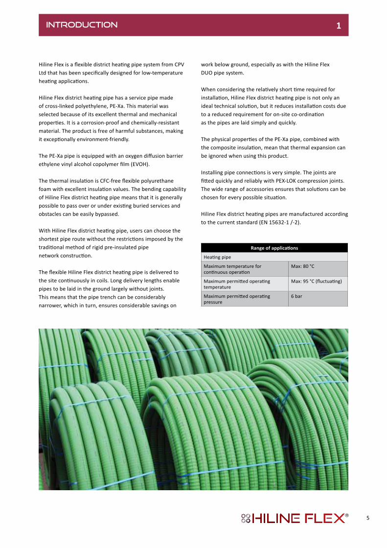
Hiline Flex is a flexible district heating pipe system from CPV Ltd that has been specifically designed for low-temperature heating applications.
Hiline Flex district heating pipe has a service pipe made of cross-linked polyethylene, PE-Xa. This material was selected because of its excellent thermal and mechanical properties. It is a corrosion-proof and chemically-resistant material. The product is free of harmful substances, making it exceptionally environment-friendly.
The PE-Xa pipe is equipped with an oxygen diffusion barrierethylene vinyl alcohol copolymer film (EVOH).
The thermal insulation is CFC-free flexible polyurethane foam with excellent insulation values. The bending capability of Hiline Flex district heating pipe means that it is generally possible to pass over or under existing buried services and obstacles can be easily bypassed.
With Hiline Flex district heating pipe, users can choose the shortest pipe route without the restrictions imposed by the traditional method of rigid pre-insulated pipe network construction.
The flexible Hiline Flex district heating pipe is delivered to the site continuously in coils. Long delivery lengths enable pipes to be laid in the ground largely without joints.This means that the pipe trench can be considerably narrower, which in turn, ensures considerable savings on
work below ground, especially as with the Hiline Flex DUO pipe system.
When considering the relatively short time required for installation, Hiline Flex district heating pipe is not only an ideal technical solution, but it reduces installation costs due to a reduced requirement for on-site co-ordination as the pipes are laid simply and quickly.
The physical properties of the PE-Xa pipe, combined with the composite insulation, mean that thermal expansion can be ignored when using this product.
Installing pipe connections is very simple. The joints are fitted quickly and reliably with PEX-LOK compression joints. The wide range of accessories ensures that solutions can be chosen for every possible situation.
Hiline Flex district heating pipes are manufactured according to the current standard (EN 15632-1 /-2).
Rangeofapplications
Heating pipe
Maximum temperature for continuous operation
Max: 80 °C
Maximum permitted operating temperature
Max: 95 °C (fluctuating)
Maximum permitted operating pressure
6 bar
5
SPECIFICATION 2.0
2.1 BONDED SYSTEM
2.1.1 Standards
Specification: Pre-insulated flexible pipe systems according to EN 15632-1/-2Fire behaviour: Building material according to DIN 4102 class B2 (normally inflammable)
2.1.2 Service Pipe
Material: High-density polyethylene (PE-HD), peroxide cross-linked (PE-Xa), colour: naturalBonding agent: PE-modified, heat stabilised, colour: redOxygen barrier: Ethylene vinyl alcohol copolymer (EVOH), heat stabilised, colour naturalSpecification: According to DIN 16892, DIN 16893 and EN 12318-2Properties: Unaffected by aggressive water; low pressure losses; very good chemical and mechanical resistance
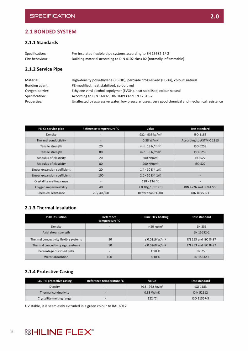
PE-Xa service pipe Reference temperature °C Value Test standard
Density - 932 - 935 kg/m3 ISO 1183
Thermal conductivity - 0.38 W/mK According to ASTM C 1113
Tensile strength 20 min. 18 N/mm2 ISO 6259
Tensile strength 80 min. 8 N/mm2 ISO 6259
Modulus of elasticity 20 600 N/mm2 ISO 527
Modulus of elasticity 80 200 N/mm2 ISO 527
Linear expansion coefficient 20 1.4 · 10 E-4 1/K -
Linear expansion coefficient 100 2.0 · 10 E-4 1/K -
Crystallite melting range - 128 - 134 °C -
Oxygen impermeability 40 ≤ 0.10g / (m3 x d) DIN 4726 and DIN 4729
Chemical resistance 20 / 40 / 60 Better than PE-HD DIN 8075 B.1
PURinsulation Reference temperature °C
HilineFlexheating Test standard
Density - > 50 kg/m3 EN 253
Axial shear strength EN 15632-2
Thermal concuctivity flexible systems 50 ≤ 0.0216 W/mK EN 253 and ISO 8497
Thermal concuctivity rigid systems 50 ≤ 0.0260 W/mK EN 253 and ISO 8497
Percentage of closed cells - ≥ 90 % EN 253
Water absorbtion 100 ≤ 10 % EN 15632-1
LLD-PEprotectivecasing Reference temperature °C Value Test standard
Density - 918 - 922 kg/m3 ISO 1183
Thermal conductivity - 0.33 W/mK DIN 52612
Crystallite melting range - 122 °C ISO 11357-3
2.1.3ThermalInsulation
2.1.4ProtectiveCasing
UV stable, it is seamlessly extruded in a green colour to RAL 6017
6

Heating,6bar
Hiline Flex in coils:Dimensions:HF 25/76 - 140/202
Hiline Flex in straight lengths:Dimensions:HF 160/250
HilineFlexheating,6bar,UNO
- The delivered coil dimensions will vary according to lengths ordered, but will be no larger than 2.8m in diameter and 0.8m to 1.2m wide
* Supplied cut to customer-specified lengths The delivered coil length may vary (+/- 5%)
Type Service pipe Nominal Outer casing Minimum Volume Weight Max length PartNumber
d x s DN D x s1 Bending radius Service pipe
mm mm mm m l/m kg/m m
25/ 76 25 x 2.3 20.4 78 x 1.9 0.45 0.32 0.90 1000 HF.2576.PU-/GN
32/ 76 32 x 2.9 26.2 78 x 1.9 0.50 0.53 1.00 1000 HF.3276.PU-/GN
40/ 91 40 x 3.7 32.6 93 x 2.1 0.55 0.83 1.39 715 HF.4091.PU-/GN
50/111 50 x 4.6 40.8 113 x 2.3 0.60 1.30 1.97 450 HF.50111.PU-/GN
63/126 63 x 5.8 51.4 128 x 2.7 1.00 2.07 2.60 291 HF.63126.PU-/GN
75/142 75 x 6.8 61.4 143 x 2.9 0.70 2.96 3.39 260 HF.75142.PU-/GN
90/162 90 x 8.2 73.6 163 x 3.2 1.00 4.25 4.56 149 HF.90162.PU-/GN
110/162 110 x 10.0 90.0 163 x 3.2 1.10 6.36 5.10 149 HF.110162.PU-/GN
110/182 110 x 10.0 90.0 183 x 3.3 1.20 6.36 5.68 86 HF.110182.PU-/GN
125/182 125 x 11.4 102.2 183 x 3.3 1.30 8.20 6.37 86 HF.125182.PU-/GN
140/202 140 x 12.7 114.6 202 x 3.3 1.40 10.31 7.60 80 HF.140202.PU-/GN
160/250 160 x 14.6 130.8 250 x 3.9 - 13.43 11.31 12* HF.160250.PU-/BK
HilineFlexheating,6bar,DUO
Type Service pipe Nominal Outer casing Minimum Volume Weight Max length PartNumber
d x s DN D x s1 Bending radius Service pipe
mm mm m l/m kg/m m
25 + 25/ 91 2 x 25 x 2.3 20.4 + 20.4 93 x 2.1 0.55 2 x 0.32 1.34 715 HF.252591.PD-/GN
32 + 32/111 2 x 32 x 2.9 26.2 + 26.2 113 x 2.3 0.60 2 x 0.53 1.87 450 HF.3232111.PD-/GN
40 + 40/126 2 x 40 x 3.7 32.6 + 32.6 128 x 2.7 1.00 2 x 0.83 2.48 291 HF.4040126.PD-/GN
50 + 50/162 2 x 50 x 4.6 40.8 + 40.8 163 x 3.2 1.10 2 x 1.30 3.96 149 HF.5050162.PD-/GN
63 + 63/182 2 x 63 x 5.8 51.4 + 51.4 183 x 3.3 1.20 2 x 2.07 5.28 86 HF.6363182.PD-/GN
*Straight lengths
SPECIFICATION 2.0
2.2 SUPPLY PROGRAMME
LLD-PE outer casing
s1
Dd
s
PE-Xa service pipe
PE-HD outer casing pipe
UNO Horizontalorientation
PE-Xa service pipePUR foam PE foil
ds
D
DUO
Verticalorientation
LLD-PE outer casing
7

SPECIFICATION 2.0
2.3.1 Pressure Loss
Hiline Flex’s PE-Xa service pipe has a very low coefficient of friction (e = 0.007 mm at 60°C) and permanently-low pressure loss throughout the lifetime of the system. With such low frictional losses, pipe diameters can often be much smaller than those using alternative materials such as steel.
Please refer to the design information in section 3.3.2 for details of pressure loss in the Hiline Flex system.
2.3.2 Heat Loss
The system’s high-performance PUR foam insulation offers minimal heat loss – some ≤ 0.0216 W/mK – in accordance with standards EN 253. Heat loss is often overlooked by specifiers and even a small difference in the chosen system’s performance, can result in increased running costs throughout the life of a system – plus additional carbon emissions.
Please refer to the design information in section 3.4 for details of heat loss in the Hiline Flex system.
2.3.3 Service Life
Operational temperatures and pressures play a very large part in the length of a system’s useful operational life. As such, great care must be taken when selecting the design parameters – details of which can be found in section 3.3.3 of this document.
8

DESIGN 3.0
3.1 INTRODUCTIONWhen designing a district heating network, it is important to choose the optimal design parameters as these will have a significant effect on a system’s ability to satisfy the demands of the heat loads that are connected. Furthermore, the system’s life expectancy can vary considerably – depending on the chosen temperatures and pressures.
This section discusses the key considerations that need to be addressed for optimal performance to be achieved. Should you have any further questions, please contact the CPV technical sales department – the contact details for which can be found on the rear page of this document.
3.2 NETWORK TYPES
3.2.1 Branched Flex
This method is one of the more common methods of network configuration. Using entirely flexible pipe for all connections, the branch connection pipes can be installed before buildings are constructed.
3.2.2 Looped Flex
This method offers the advantage of there being no pipe connections below ground. This is better suited to smaller networks.
9

DESIGN3.0
3.3 PIPE SIZING
3.3.1Introduction
With a much improved frictional coefficient, PE-Xa pipes offer great advantages over their steel counterparts. When sizing Hiline Flex pipes, it’s recommended that a comparison is made between the energy losses in a system and the pump capacity. Heat demands vary throughout the year and as such, the full pumping load is only reached on a few days every year. By striking a balance on the energy loss and pumping capacity, pipe dimensions can be kept lower and savings made on both the capital cost of installation and its long-term operation.
To calculate a pipe’s size, the Pressure Loss Nomogram in section 3.3.2 can be used to estimate pressure loss.
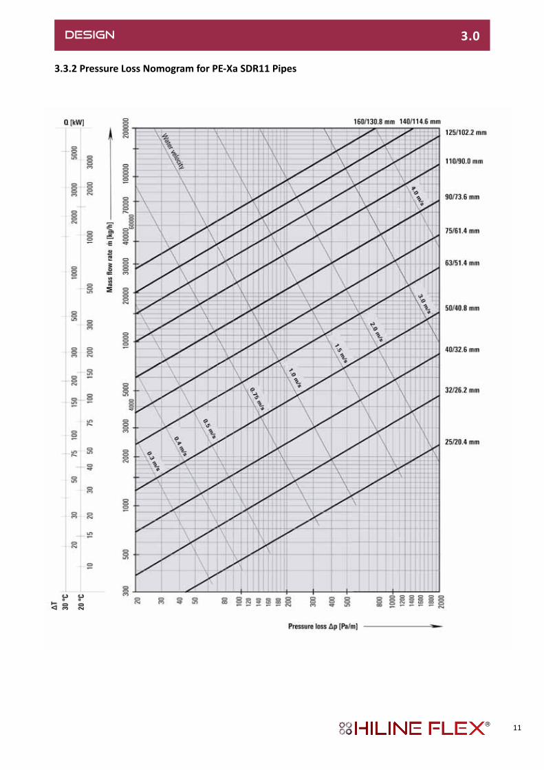
3.3.2 Pressure Loss Nomogram
Using the Pressure Loss Nomogram on the following page, select the temperature difference ∆T from the left-hand vertical axis. Two examples are shown, 30°C and 20°C.
Using the relevant vertical scale, select the connected heat load Q in kW. Then, move horizontally over the Nomogram to determine which of the pipe diameters will provide the optimal flow rate. These pipe dimensions are represented by the thick black lines – with their corresponding dimensions shown on the right-hand vertical axis.The vertical lines running from the horizontal axis show the Pressure Loss - ∆p in Pa/m.
By using the thinner diagonal lines – following them up wards, the Mass Flow Rate in kg/h can be determined. As with the pressure drop values, this will vary according to the chosen pipe dimension.Example Calculation
• Assumed flow temperature: 80°C• System Temperature Drop ∆T: 30°C• Connected Heat Load Q: 200kW
First two options for Hiline Flex pipe diameter:(1) 75/61.4mm Hiline Flex – with a pressure drop of 45 Pa/m (2) 63/51.4mm Hiline Flex – with a pressure drop of 100 Pa/m
Choose a pipe dimension from the available options according to the preferred pressure drop figure.
3.2.3BranchedHybrid
This method combines the advantages and larger dimension availability of pre-insulated steel systems for the arterial mains distribution – with the flexibility and speed of installation that individual branch connections in flexible PE-Xa pre-insulated pipe offers.
10
DESIGN 3.0
3.3.2 Pressure Loss Nomogram for PE-Xa SDR11 Pipes
11

DESIGN3.0
3.3.3ServiceLifeIntroduction
The chosen operational flow temperatures and pressures can have a great effect on the life expectancy calculations for a PE-Xa-based pre-insulated pipe system. The tables below illustrate the expected values at a range of different temperatures and pressures. Should you require specific calculations, please contact our Technical Sales department, the contact details for which can be found in the rear of this document.
Long-termbehaviour:
The values have a safety factor of 1.25 and are based on a series of measurements covering an average of 32,000 hours. They can be compared with Table 5 as per DIN 16893. All values have been testedand confirmed by the competent organizations in various countries.The max. operating temperature is 95 °C but accomodates a short-term over temperature (fault temperature) of 110 °C.
LifetimecalculationusingMiner‘sRule
Lifetime calculation for fluctuating operating temperatures will be calculated to EN ISO 13760. A typical fluctuating temperature distribution for the flow in a district heating system gives an average temperature/year of approx. 66 °C.
Operatingtemperature
°C
HeatingOperatingpressure(bar)
1 year 5 year 10 year 25 year 50 year
10 17.9 17.5 17.4 17.2 17.1
20 15.8 15.5 15.4 15.2 15.1
30 14.0 13.8 13.7 13.5 13.4
40 12.5 12.2 12.1 12.0 11.9
50 11.1 10.9 10.8 10.7 10.6
60 9.9 9.7 9.7 9.5 9.5
70 8.9 8.7 8.6 8.5 8.5
80 8.0 7.8 7.7 7.6 -
90 7.2 7.0 6.9 - -
95 6.8 6.6 6.6 - -
1 MPA= 10 bar
OperatingTemperature
Example 1Annual
Operatingtime
Example 2Annual
Operatingtime
Example 3Annual
Operatingtime
°C h h h
95 3.3 0 0
90 292 50 50
85 0 100 1,000
80 8,468 200 3,450
75 0 2,000 1,000
70 0 2,410 0
65 0 4,000 0
60 0 0 0
total 8,763.3 8,760 5,500
ExampleofapplicationThe basis is a typical temperature collective over one year, with fluctuating operation. (EN 15632-2)1 year= 365 days= 8,760 hours.
12

DESIGN 3.0
3.4 HEAT LOSSThe Hiline Flex has a high-performance PUR foam insulation which offers minimal heat loss – some ≤ 0.0216 W/mK – in accordance with the EN 253 standard. The tables below provide heat loss values for a range of average operating temperatures.
Note:Due to the planned revision of standards, the heat losses are not shownas specified within EN 15632.
Type of installation, HF UNO: 2-pipe, laid in the groundType of installation, HF DUO: 1-pipe, laid in the groundPipe distance: a = 0.10 m Cover above pipe: H = 0.80 mGround temperature: TE = 10 °CSoil conductivity: λE = 1.0 W/mKConductivity of PUR foam: λPU = 0.0216 W/mK*Conductivity of PUR foam: λ PU = 0.0260 W/mKConductivity of PEX pipe: λ PEXa = 0.38 W/mKConductivity of PE pipe: λ PEXa = lPE = 0.33 W/mK
Heat loss during operation:q = U (TB -TE) [W/m]U = Heat transfer coefficient [W/mK]TB = Average operating temperature [°C]TE = Average ground temperature [°C]VL = FlowRL = Return
Hiline Flex UNO
Heat losses q [W/m] for one UNO pipe
Hiline Flex UNO
U-value[W/mK]
AverageoperatingtemperatureTB[°C]
40° 50° 60° 70° 80°
25/ 76 0.1142 3.43 4.57 5.71 6.85 7.99
32/ 76 0.1442 4.33 5.77 7.21 8.65 10.09
40/ 91 0.1510 4.53 6.04 7.55 9.06 10.57
50/111 0.1551 4.65 6.20 7.76 9.31 10.86
63/126 0.1767 5.30 7.07 8.84 10.60 12.37
75/142 0.1908 5.72 7.63 9.54 11.45 13.36
90/162 0.2057 6.17 8.23 10.29 12.34 14.40
110/162 0.2957 8.87 11.83 14.79 17.74 20.70
110/182 PLUS 0.2355 7.07 9.42 11.78 14.13 16.49
125/182 0.3026 9.08 12.10 15.13 18.16 21.18
140/202 0.3084 9.25 12.34 15.42 18.50 21.59
160/250* 0.3028 9.08 12.11 15.14 18.17 21.20
Heatlossesq[W/m]foroneDuopipe(F&R)
Hiline Flex DUO
U-value[W/mK]
AverageoperatingtemperatureTB[°C]
40° 50° 60° 70° 80°
25 + 25/ 91 0.1786 5.36 7.14 8.93 10.72 12.50
32 + 32/111 0.1829 5.49 7.32 9.15 10.97 12.80
40 + 40/126 0.2108 6.32 8.43 10.54 12.65 14.76
50 + 50/162 0.1954 5.86 7.82 9.77 11.72 13.68
63 + 63/182 0.2381 7.14 9.52 11.91 14.29 16.67
HilineFlexDUO(flowandreturninoneoutercasing)
a = 0.1 m
H =
0.8
m
TE E
RL (return)
VL (flow)
H =
0.8
m
TE
E
13

3.5 THERMAL EXPANSIONThe Hiline Flex system does not require any expansion bellows or compensators when installed in trenches. This is due to the frictional forces between the pipe’s corrugated LDPE outer casing and the compacted soil being greater than the expansion forces exerted by the plastic pipe.
3.6 TRENCH REQUIREMENTS
3.6.1Introduction
The pipe trench’s dimensions can affect the load bearing capabilities of the buried pipe system. Therefore, it is important that the dimensions laid out in section 3.6.3 are adhered to. Adequate space must also be provided at jointing areas to allow for free access for the installation process.
The minimum cover for buried pipes is 600mm down to a maximum of 2.6m.Please contact us if your project’s requirement necessitates a deviation from these limits.
3.6.2TrafficLoadings
For buried systems under road structures, loading classifications SWL 30 or SWL 60 must be complied with – in accordance with DIN 1072. For loads greater than SWL 30 300kN total, a load-distributing super structure is required in compliance with the demands of RSt075 (or equivalent).
With no traffic load, the minimum trench depth T can be reduced by 200mm.
DESIGN 3.0
14

DESIGN 3.0
3.6.3 Trench Dimensions 1 Pipe warning tape; see sheet HF 4.4.32 Excavated material3 Pipe bedding media (a) Sand - Grade 0/4 (b) Pea shingle - 6-8mm (rounded)
SLW 30 300 kN total load as per DIN 1072; if subject to higher traffic loads (e.g. SLW 60), a load-distributing superstructure as per RStO75 is required. With no traffic load, the minimum trench depth T can be reduced by 20 cm.
Installation depth:Max. installation depth: 2.6 mOur approval is required for installation at greater depths.
Service pipe Ø D mm
WidthB
cm
DepthT
cm
Minimumbendingradius
m
76 45 80 0.7
91 50 80 0.8
111 55 85 0.9
126 55 85 1.0
142 60 85 1.1
162 65 90 1.2
182 70 95 1.4
202 75 95 1.4
250 80 100 -
Service pipe Ø D mm
WidthB
cm
DepthT
cm
Minimumbendingradius
m
91 30 80 0.8
111 30 85 0.9
126 35 85 1.0
142 35 85 1.1
162 35 90 1.2
182 38 95 1.4
1010
3060
D
T
D10 10B
1 2 3
Dimensions in cm
10 10 10 10 10D D D DB (4 x D + 5 x 10)
1010
30D
60
T
1 2 3
10 10 10D D
105
1030
DD
60
T
B
1 2 3
1 2 3
1010
3060
D
T
10 10DDB10
15

3.6.4 Trenches in Special Conditions
3.6.4.1 Trenches on a Slope
Where trenches are on an incline, backfill material must be prevented from being washed away by ground water. This can be done by the installation of concrete plates cast into position at regular intervals along the section of sloping trench.
3.6.4.2 Waterlogged Ground
Where the bottom of the trench may be unstable from waterlogged, boggy ground or marshland, it is important that measures are taken to provide a consistent support along the entire length of the pipe system. This can include the use of general construction methods such as non-woven fabric.
3.6.5 Proximity to Other Services
Utility/Service Parallel <5m or crossover Parallel >5m
1kV Electricity Cables 0.3m 0.3m
10kV or 30kV Electricity Cables 0.6m 0.7m
Natural Gas or Water Supplies 0.2m 0.4m
Restraining plates
DESIGN 3.0
Gravel
Non woven fabric
It is important to observe any relevant standards and regulations for the positioning of buried utilities. An example of this includes potable water supplies – where they must not be warmed by district heating mains. The table above offers some guide values for common services, but please ensure that local and national requirements are strictly adhered to.
16
DESIGN 3.0
3.7 SYSTEM CONNECTIONS
3.7.1 Horizontal Building Entry
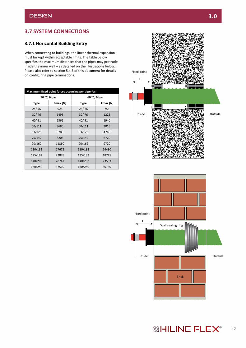
When connecting to buildings, the linear thermal expansion must be kept within acceptable limits. The table below specifies the maximum distances that the pipes may protrude inside the inner wall – as detailed on the illustrations below.Please also refer to section 5.4.3 of this document for details on configuring pipe terminations.
OutsideInside
L
Fixed point
OutsideInside
L
Fixed point
Wall sleeve (compression type)
Concrete
Wall sealing ring
Brick
Maximumfixedpointforcesoccurringperpipefor:
90°C,6bar 60°C,6bar
Type Fmax [N] Type Fmax [N]
25/ 76 925 25/ 76 755
32/ 76 1495 32/ 76 1225
40/ 91 2365 40/ 91 1940
50/111 3685 50/111 3015
63/126 5785 63/126 4740
75/142 8205 75/142 6720
90/162 11860 90/162 9720
110/182 17675 110/182 14480
125/182 22878 125/182 18745
140/202 28747 140/202 23553
160/250 37510 160/250 30730
17
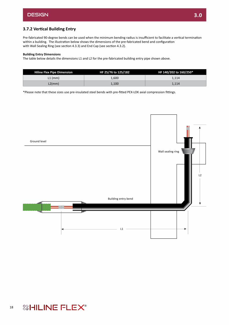
3.7.2VerticalBuildingEntry
Pre-fabricated 90-degree bends can be used when the minimum bending radius is insufficient to facilitate a vertical termination within a building. The illustration below shows the dimensions of the pre-fabricated bend and configurationwith Wall Sealing Ring (see section 4.3.3) and End Cap (see section 4.3.2).
Building Entry DimensionsThe table below details the dimensions L1 and L2 for the pre-fabricated building entry pipe shown above.
Hiline Flex Pipe Dimension HF 25/76 to 125/182 HF 140/202 to 160/250*
L1 (mm) 1,600 1,114
L2(mm) 1,100 1,114
*Please note that these sizes use pre-insulated steel bends with pre-fitted PEX-LOK axial compression fittings.
Ground level
L1
L2
DESIGN 3.0
Building entry bend
Wall sealing ring
18
DESIGN 3.0
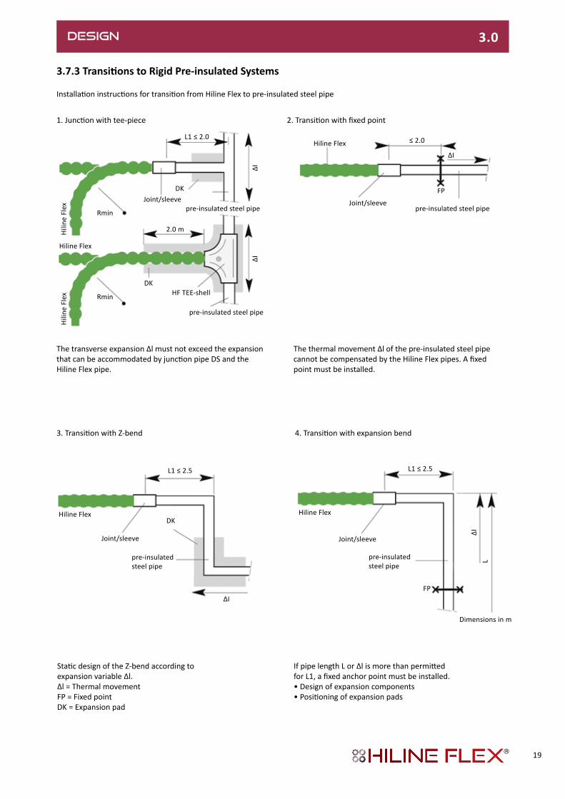
3.7.3TransitionstoRigidPre-insulatedSystems
Installation instructions for transition from Hiline Flex to pre-insulated steel pipe
The transverse expansion Δl must not exceed the expansion that can be accommodated by junction pipe DS and the Hiline Flex pipe.
The thermal movement Δl of the pre-insulated steel pipe cannot be compensated by the Hiline Flex pipes. A fixed point must be installed.
3. Transition with Z-bend 4. Transition with expansion bend
L1 ≤ 2.0
DK
Hiline Flex
Hili
ne F
lex
Hili
ne F
lex
Joint/sleevepre-insulated steel pipe
pre-insulated steel pipe
DK
Rmin
Rmin
2.0 m
HF TEE-shell
∆I∆I
Hiline Flex
Joint/sleevepre-insulated steel pipe
≤ 2.0
∆I
FP
L1 ≤ 2.5
DKHiline Flex
∆I
pre-insulatedsteel pipe
Joint/sleeve
L1 ≤ 2.5
Hiline Flex
FP
Dimensions in m
pre-insulated steel pipe
Joint/sleeve
∆IL
1. Junction with tee-piece 2. Transition with fixed point
Static design of the Z-bend according to expansion variable Δl.Δl = Thermal movementFP = Fixed pointDK = Expansion pad
If pipe length L or Δl is more than permitted for L1, a fixed anchor point must be installed. • Design of expansion components• Positioning of expansion pads
19

PRODUCT RANGE 4.0
4.1 PRE-INSULATED
4.1.1 Pre-insulated PipesUNO/DUO range
Hiline Flex in coils:Dimensions:HF 25/76 - 140/202
Hiline Flex in straight lengths:Dimensions:HF 160/250
HilineFlexheating,6bar,UNO
HilineFlexheating,6bar,DUO
The delivered coil dimensions will vary according to lengths ordered, but will be no larger than 2.8m in diameter and 0.8m to 1.2m wide
Type Service pipe Nominal Outer casing Minimum Volume Weight Max length PartNumber
d x s DN D x s1 Bending radius Service pipe
mm mm mm m l/m kg/m m
25/ 76 25 x 2.3 20.4 78 x 1.9 0.45 0.32 0.90 1000 HF.2576.PU-/GN
32/ 76 32 x 2.9 26.2 78 x 1.9 0.50 0.53 1.00 1000 HF.3276.PU-/GN
40/ 91 40 x 3.7 32.6 93 x 2.1 0.55 0.83 1.39 715 HF.4091.PU-/GN
50/111 50 x 4.6 40.8 113 x 2.3 0.60 1.30 1.97 450 HF.50111.PU-/GN
63/126 63 x 5.8 51.4 128 x 2.7 1.00 2.07 2.60 291 HF.63126.PU-/GN
75/142 75 x 6.8 61.4 143 x 2.9 0.70 2.96 3.39 260 HF.75142.PU-/GN
90/162 90 x 8.2 78.6 163 x 3.2 1.00 4.25 4.56 149 HF.90162.PU-/GN
110/162 110 x 10.0 90.0 163 x 3.2 1.10 6.36 5.10 149 HF.110162.PU-/GN
110/182 110 x 10.0 90.0 183 x 3.3 1.20 6.36 5.68 86 HF.110182.PU-/GN
125/182 125 x 11.4 102.2 183 x 3.3 1.30 8.20 6.37 86 HF.125182.PU-/GN
140/202 140 x 12.7 114.6 202 x 3.3 1.40 10.31 7.60 80 HF.140202.PU-/GN
160/250 160 x 14.6 130.8 250 x 3.9 - 13.43 11.31 12* HF.160250.PU-/BK
Type Service pipe Nominal Outer casing Minimum Volume Weight Max length PartNumber
d x s DN D x s1 Bending radius Service pipe
mm mm mm m l/m kg/m m
25 + 25/ 91 2 x 25 x 2.3 20.4 + 20.4 93 x 2.1 0.55 2 x 0.32 1.34 715 HF.252591.PD-/GN
32 + 32/111 2 x 32 x 2.9 26.2 + 26.2 113 x 2.3 0.60 2 x 0.53 1.87 450 HF.3232111.PD-/GN
40 + 40/126 2 x 40 x 3.7 32.6 + 32.6 128 x 2.7 1.00 2 x 0.83 2.48 291 HF.4040126.PD-/GN
50 + 50/162 2 x 50 x 4.6 40.8 + 40.8 163 x 3.2 1.10 2 x 1.30 3.96 149 HF.5050162.PD-/GN
63 + 63/182 2 x 63 x 5.8 51.4 + 51.4 183 x 3.3 1.20 2 x 2.07 5.28 86 HF.6363182.PD-/GN
Dd
s
PE-Xa service pipe
PE-HD outer casing pipe
UNO Horizontalorientation
PE-Xa service pipePUR foam PE foil
ds
D
DUO
Verticalorientation
LLD-PE outer casing
20

4.1.2.1 90-Degree / Building Entry Bend
Bend, 90°Dimensions: HF 25/76 - 125/182
Bend, 90° Steel with welded-on PEX-LOK compression coupling Dimensions: HF 140/202 - 160/250
Hiline Flex UNO
Hiline Flex DUO
1114
Dimensions in mm
1114
Please Note: Hiline Flex pre-insulated bends in dimensions 140/202 and 160/250 are pre-insulated steel, fitted with PEX-LOK compression connections at each end – as detailed in section 4.2.1.4.
PRODUCT RANGE 4.0
4.1.2Pre-insulatedFittings
Type PEX service pipe Weight Part Nod x smm kg/unit
25/ 76 25 x 2.3 2.30 HF.2576.LPU
32/ 76 32 x 2.9 2.50 HF.3276.LPU
40/ 91 40 x 3.7 3.47 HF.4091.LPU
50/111 50 x 4.6 4.92 HF.50111.LPU
63/126 63 x 5.8 6.50 HF.63126.LPU
75/142 75 x 6.8 8.47 HF.75142.LPU
90/162 90 x 8.2 11.40 HF.90162.LPU
110/162 110 x 10.0 14.23 HF.110162.LPU
110/182 110 x 10.0 16.19 HF.110182.LPU
125/182 125 x 11.4 17.20 HF.125182.LPU
140/225 140 x 12.7 40.95 HF.140202.LPU
160/250 160 x 14.6 58.40 HF.160250.LPU
Type PEX service pipe Weight Part No
d x smm kg/unit
25 + 25/ 91 2 x 25 x 2.3 4.32 HF.252591.LPD*32 + 32/111 2 x 32 x 2.9 4.67 HF.3232111.LPD*40 + 40/126 2 x 40 x 3.7 7.42 HF.4040126.LPD*50 + 50/162 2 x 50 x 4.6 9.90 HF.5050162.LPD*63 + 63/182 2 x 63 x 5.8 13.96 HF.6363182.LPD*
*Please specify Horizontal ‘H’ or Vertical ‘V’ configuration in part number suffix.
UNO
A
1100
1600
250
250
250
DUOHorizontal
DUOVertical
21

PRODUCT RANGE 4.0
4.1.2.2 Flat Tee
Dimension HF 140/225 - 160/250
HilineFlexFlatTee-Joint–PartNumbers
PartNumbers: to determine the part number, please take the value shown in the table above and prefix with HF. So a 160/250 main pipe with a 125/182 branch tee would be HF.160.TF2 We can supply tee-pieces with different branches on request
Outer casing Branch,Ød2
Ø d1 Ø d3 25/76 32/76 40/91 50/111 63/126 75/142 90/162 110/162 110/182 125/182 140/202 160/250
125/182 - 125/182 125.TF9 125.TF8 125.TF7 125.TF6 125.TF5 125.TF4 125.TF3 125.TF2 125.TF1 125.TF- - -
140/202 - 140/202 140.TF10 140.TF9 140.TF8 140.TF7 140.TF6 140.TF5 140.TF4 140.TF3 140.TF2 140.TF1 140.TF- -
160/250 - 160/250 160.TF11 160.TF10 160.TF9 160.TF8 160.TF7 160.TF6 160.TF5 160.TF4 160.TF3 160.TF2 160.TF1 160.TF-
A
1
2
3
4
5
6
View A
Flat Tee Assembly: 1 Tee-piece, pre-insulated steel pipe (St 37.0)2 Heat-shrink bands3 Heat-shrink oversleeve4 PUR foam kit5 PEX-LOK connector6 Hiline Flex pipe
Ø d1 Ø d3
Ø d2
Pre-insulatedsteel pipe
Ø d3Ø d3
Ø d2
22

4.1.2.3 Cranked Tee
Dimension HF 140/225 - 160/250
HilineFlexCrankedTee-Joint–PartNumbers
PartNumbers: to determine the part number, please take the value shown in the table above and prefix with HF. So a 160/250 main pipe with a 125/182 branch tee would be HF.160.TC1 We can supply tee-pieces with different branches on request
Outer casing Branch,Ød2
Ø d1 Ø d3 25/76 32/76 40/91 50/111 63/126 75/142 90/162 110/162 110/182 125/182 140/202 160/250
125/182 - 125/182 125.TC9 125.TC8 125.TC7 125.TC6 125.TC5 125.TC4 125.TC3 125.TC2 125.TC1 125.TC- - -
140/202 - 140/202 140.TC10 140.TC9 140.TC8 140.TC7 140.TC6 140.TC5 140.TC4 140.TC3 140.TC2 140.TC1 140.TC- -
160/250 - 160/250 160.TC11 160.TC10 160.TC9 160.TC8 160.TC7 160.TC6 160.TC5 160.TC4 160.TC3 160.TC2 160.TC1 160.TC-
A
1
2
3
4
5
6
View A
45°
Pre-insu
lated
steel p
ipe
Cranked Tee Assembly: 1 Tee-piece, pre-insulated steel pipe (St 37.0)2 Heat-shrink bands3 Heat-shrink oversleeve4 PUR foam kit5 PEX-LOK connector6 Hiline Flex pipe
PRODUCT RANGE 4.0
Ø d1 Ø d3
Ø d2
23

PRODUCT RANGE 4.0
Hiline Flex DUO / 2 x Hiline Flex UNO
UNO pipes Ø D2 and D3 D DUO HF pipe Ø D1 Part Nomm mm mm mm
2 x 25/ 76 75 25 + 25/ 91 90 HF.25257691.UDA-PP*2 x 32/ 76 75 32 + 32/111 110 HF.32327691.UDA-PP*2 x 40/ 91 90 40 + 40/126 125 HF.404091126.UDA-PP*
2 x 50/ 111 110 50 + 50/162 160 HF.5050111162.UDA-PP*2 x 63/ 126 125 63 + 63/182 180 HF.6363126182.UDA-PP*
HF UNO
HF UNO RL (return)
VL (flow) (right)
250300250+20250
1800
300
min. 650
Ø D1
Ø D2
RL return
11 0/+1
Dimensions in mm
VL (flow) (bottom)
Note: With UNO pipe, in the direction of flow, the forward flow (VL) is always on the right and with DUO pipe, it is always at the bottom.
4.1.2.5 Pre-insulated Valves
These pre-insulated valves are from the Hiline Steel (Metric) range, with welded-on PEX-LOK axial compression fittings as detailed in section 4.2.1.4. These valves are supplied with extended handles and street boxes.
Hiline Flex Size Dimensions(mm) Part NoService Pipe OD/Casing OD (mm) Nominal Diameter(mm)
HF UNO D2 D1 H L*25/76 20 90 380 1,300 HF.25.BVU32/76 25 110 384 1,320 HF.32.BVU40/91 32 110 388 1,340 HF.40.BVU
50/111 40 125 403 1,370 HF.50.BVU63/126 50 140 410 1,380 HF.63.BVU75/142 65 160 414 1,390 HF.75.BVU90/162 80 200 427 1,390 HF.90.BVU
110/162 100 225 450 1,680 HF.110.BVU110/182 100 225 450 1,680 HF.110.BVU125/225 125 315 455 1,716 HF.125.BVU140/225 125 315 455 1,724 HF.140.BVU160/250 150 400 457 1,728 HF.160.BVUHF DUO
25+25/91 20+20 110 384 1,300 HF.25.BVD32+32/111 25+25 125 403 1,320 HF.32.BVD40+40/126 32+32 140 410 1,340 HF.40.BVD50+50/162 40+40 225 450 1,370 HF.50.BVD63+63/182 50+50 250 455 1,380 HF.63.BVD
* This dimension includes the welded-on PEX-LOK axial compression connectors. Special reducing casing joint kits may be required to accommodate certain sizes. Please contact us for details.
Ø D3
Długo
��wgzamów
ienia
Klucz
L
D2
H
D1
4.1.2.4 Y-Piece
* Please specify V (Vertical) or H (Horizontal) configuration for DUO pipe connections.
Vertical orientation Horizontal orientation
11 0/+1
24
PRODUCT RANGE 4.0
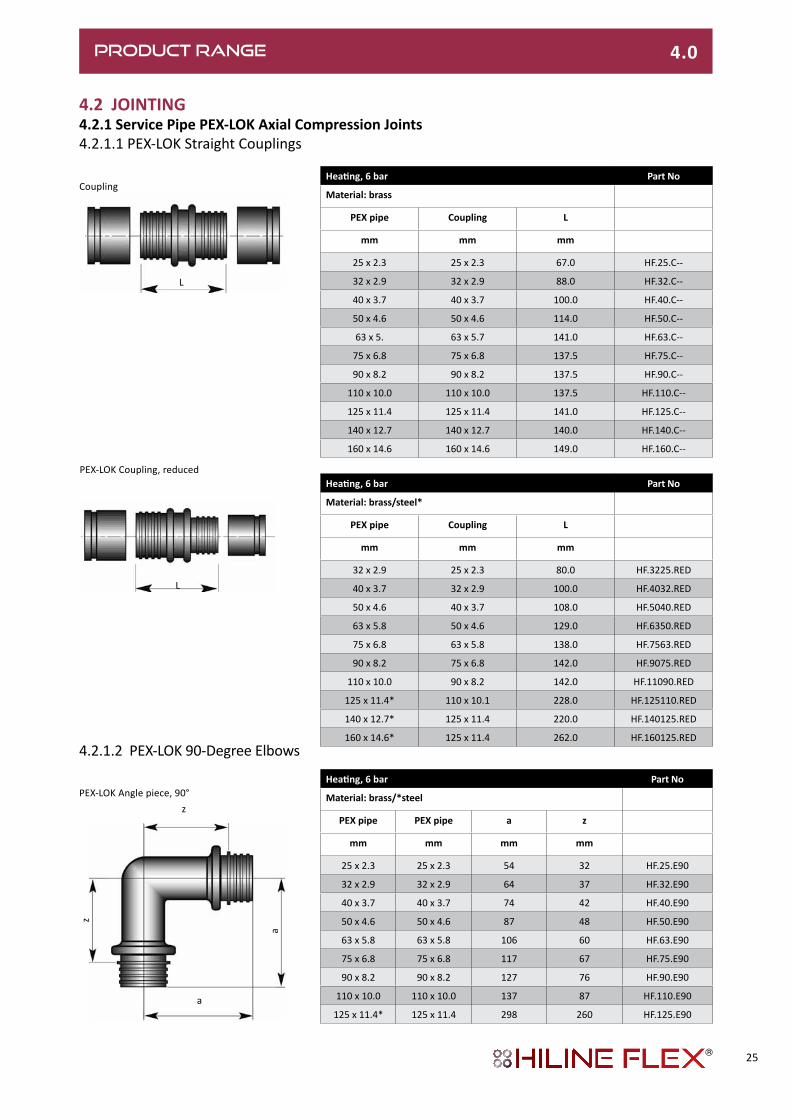
4.2 JOINTING4.2.1 Service Pipe PEX-LOK Axial Compression Joints4.2.1.1 PEX-LOK Straight Couplings
4.2.1.2 PEX-LOK 90-Degree Elbows
Heating,6bar Part No
Material:brass
PEX pipe Coupling L
mm mm mm
25 x 2.3 25 x 2.3 67.0 HF.25.C--
32 x 2.9 32 x 2.9 88.0 HF.32.C--
40 x 3.7 40 x 3.7 100.0 HF.40.C--
50 x 4.6 50 x 4.6 114.0 HF.50.C--
63 x 5. 63 x 5.7 141.0 HF.63.C--
75 x 6.8 75 x 6.8 137.5 HF.75.C--
90 x 8.2 90 x 8.2 137.5 HF.90.C--
110 x 10.0 110 x 10.0 137.5 HF.110.C--
125 x 11.4 125 x 11.4 141.0 HF.125.C--
140 x 12.7 140 x 12.7 140.0 HF.140.C--
160 x 14.6 160 x 14.6 149.0 HF.160.C--
Heating,6bar Part No
Material:brass/steel*
PEX pipe Coupling L
mm mm mm
32 x 2.9 25 x 2.3 80.0 HF.3225.RED
40 x 3.7 32 x 2.9 100.0 HF.4032.RED
50 x 4.6 40 x 3.7 108.0 HF.5040.RED
63 x 5.8 50 x 4.6 129.0 HF.6350.RED
75 x 6.8 63 x 5.8 138.0 HF.7563.RED
90 x 8.2 75 x 6.8 142.0 HF.9075.RED
110 x 10.0 90 x 8.2 142.0 HF.11090.RED
125 x 11.4* 110 x 10.1 228.0 HF.125110.RED
140 x 12.7* 125 x 11.4 220.0 HF.140125.RED
160 x 14.6* 125 x 11.4 262.0 HF.160125.RED
Heating,6bar Part No
Material:brass/*steel
PEX pipe PEX pipe a z
mm mm mm mm
25 x 2.3 25 x 2.3 54 32 HF.25.E90
32 x 2.9 32 x 2.9 64 37 HF.32.E90
40 x 3.7 40 x 3.7 74 42 HF.40.E90
50 x 4.6 50 x 4.6 87 48 HF.50.E90
63 x 5.8 63 x 5.8 106 60 HF.63.E90
75 x 6.8 75 x 6.8 117 67 HF.75.E90
90 x 8.2 90 x 8.2 127 76 HF.90.E90
110 x 10.0 110 x 10.0 137 87 HF.110.E90
125 x 11.4* 125 x 11.4 298 260 HF.125.E90
Coupling
L
PEX-LOK Coupling, reduced
L
PEX-LOK Angle piece, 90°z
z
a
a
25

PRODUCT RANGE 4.0d1
4.2.1.3 PEX-LOK Tee Couplings
PartNumbers: to determine the part number, please take the value shown in the table above and prefix with HF. and suffix with a .TCS So a 125mm main pipe with a 75mm branch tee would be HF.12575125.TCS
• PEX-LOK tee-pieces made of steel can be supplied on request• Other PEX-LOK tee-pieces can be supplied on request.• Tees for dimension DN 150 is supplied in prefabricated and pre-insulated form (see 4.1.2.2 and 4.1.2.3).
Material:The material depends upon the chosen size: • Brass CuZn39Pb3 (DN 20 - DN 50),• Gunmetal Rg7 (DN 65 - DN 100)• Steel St 37.0, welded (DN 125)
Heating,6bar Branch,Ød2Ø d1 Ø d3 mm
mm 25 x 2.3 32 x 2.9 40 x 3.7 50 x 4.6 63 x 5.8 75 x 6.8 90 x 8.2 110 x 10.0 125 x 11.4
25 x 2.3 - 25 x 2.3 252525
32 x 2.9 - 32 x 2.9 322532 323232
32 x 2.9 - 25 x 2.3 322525
40 x 3.7 - 40 x 3.7 402540 403240 404040
40 x 3.7 - 32 x 2.9 402532 403232
50 x 4.6 - 50 x 4.6 502550 503250 504050 505050
50 x 4.6 - 40 x 3.7 502540 503240 504040
63 x 5.8 - 63 x 5.8 632563 633263 634063 635063 636363
63 x 5.8 - 50 x 4.6 632550 633250 634050 635050
75 x 6.8 - 75 x 6.8 752575 753275 754075 755075 756375 757575
75 x 6.8 - 63 x 5.8 752563 753263 754063 755063 756363
90 x 8.2 - 90 x 8.2 902590 903290 904090 905090 906390 907590 909090
90 x 8.2 - 75 x 6.8 902575 903275 904075 905075 906375 907575
110 x 10.0 - 110 x 10.0 11025110 11032110 11040110 11050110 11063110 11075110 11090110 110110110
110 x 10.0 - 90 x 8.2 1102590 1103290 1104090 1105090 1106390 1107590 1109090
125 x 11.4 - 125 x 11.4 12525125 12532125 12540125 12550125 12563125 12575125 12590125 125110125 125125125
d2 d2
Brass Steel
d3 d1 d3
26

PRODUCT RANGE 4.0
4.2.1.4 Transition Couplings
PEX-LOK Axial compression-type connector with external thread (BSP)
PEX-LOK Axial compression-type connector with weld end
Heating,6bar Part NoMaterial:brass
PEX pipe Screwed connector Lmm mm mm
25 x 2.3 25 x 2.3 - ¾“ 62 HF.25.MA-32 x 2.9 32 x 2.9 - 1“ 72 HF.32.MA-40 x 3.7 40 x 3.7 - 1¼“ 82 HF.40.MA-50 x 4.6 50 x 4.6 - 1½“ 89 HF.50.MA-63 x 5.8 63 x 5.7 - 2“ 109 HF.63.MA-75 x 6.8 75 x 6.8 - 2½“ 110 HF.75.MA-90 x 8.2 90 x 8.2 - 3“ 115 HF.90.MA-
110 x 10.0 110 x 10.0 - 4“ 120 HF.110.MA-125 x 11.4 125 x 11.4 - 5” 125 HF.125.MA-160 x 14.6 160 x 14.6 - 6” 130 HF.160.MA-
Heating,6bar Part NoMaterial:Steel
PEX pipe Weld end L1 L2mm mm mm mm
25 x 2.3 26.9 x 2.65 50 20 HF.25.PSA32 x 2.9 33.7 x 2.3 60 24 HF.32.PSA40 x 3.7 42.4 x 2.6 70 29 HF.40.PSA50 x 4.6 48.3 x 2.6 85 37 HF.50.PSA63 x 5.8 60.3 x 2.9 90 32 HF.63.PSA75 x 6.8 76.1 x 3.2 95 35 HF.75.PSA90 x 8.2 88.9 x 3.2 95 35 HF.90.PSA
110 x 10.0 114.3 x 3.6 90 30 HF.110.PSA125 x 11.4 139.7 x 3.6 108 48 HF.125.PSA140 x 12.7 139.7 x 3.6 112 50 HF.140.PSA160 x 14.6 168.3 x 4.1 114 50 HF.160.PSA
L
L1
L2
St 37
Heating,6bar Part NoMaterial:Brass
PEX pipe Screwed connector Lmm mm mm
25 x 2.3 25 x 2.3 - 3/4” 53 HF.25.SMA32 x 2.9 32 x 2.9 - 1” 63 HF.32.SMA40 x 3.7 40 x 3.7- 11/4” 67 HF.40.SMA50 x 4.6 50 x 4.8 - 11/2” 71 HF.50.SMA63 x 5.8 63 x 5.7 - 2” 80 HF.63.SMA75 x 6.8 75 x 6.8 - 21/2” 92 HF.75.SMA90 x 8.2 90 x 8.2 - 3” 92 HF.90.SMA
110 x 10.0 110 x 10.0 - 4” 102 HF.110.SMA
Heating,6bar Part NoMaterial:Brass
PEX pipe Weld end Lmm mm mm
25 x 2.3 26.9 x 2.65 180 HF.25.SPSA32 x 2.9 33.7 x 2.3 180 HF.32.SPSA40 x 3.7 42.4 x 2.6 185 HF.40.SPSA50 x 4.6 48.3 x 2.6 190 HF.50.SPSA63 x 5.8 60.3 x 2.9 195 HF.63.SPSA75 x 6.8 78.1 x 3.2 200 HF.75.SPSA90 x 8.2 88.9 x 3.2 240 HF.90.SPSA
110 x 10.0 114.3 x 3.6 280 HF.110.SPSA
PEX-LOK Screw-type connector with external thread (BSP - for above-ground use only)
PEX-LOK Screw-type connector with weld end (for above-ground use only).
We offer a pre-fitting service for transition couplings on Hiline Flex pipes up to 63mm (DN 51.4mm). Pre-fitting applies to PEX-LOK Axial compression fittings only (and includes ball valves). Please contact us for details.
27
PRODUCT RANGE 4.0
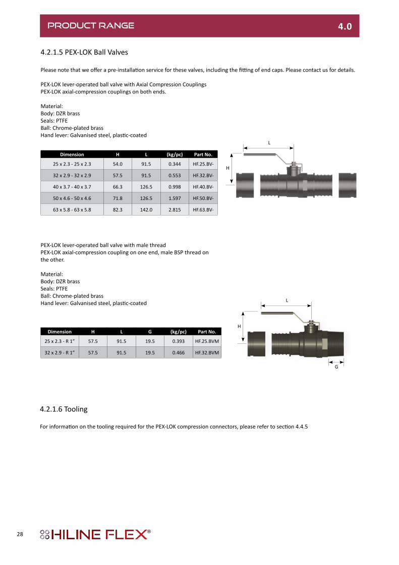
4.2.1.5 PEX-LOK Ball Valves
Dimension H L (kg/pc) Part No.
25 x 2.3 - 25 x 2.3 54.0 91.5 0.344 HF.25.BV-
32 x 2.9 - 32 x 2.9 57.5 91.5 0.553 HF.32.BV-
40 x 3.7 - 40 x 3.7 66.3 126.5 0.998 HF.40.BV-
50 x 4.6 - 50 x 4.6 71.8 126.5 1.597 HF.50.BV-
63 x 5.8 - 63 x 5.8 82.3 142.0 2.815 HF.63.BV-
Please note that we offer a pre-installation service for these valves, including the fitting of end caps. Please contact us for details.
PEX-LOK lever-operated ball valve with Axial Compression CouplingsPEX-LOK axial-compression couplings on both ends.
Material:Body: DZR brassSeals: PTFEBall: Chrome-plated brassHand lever: Galvanised steel, plastic-coated
PEX-LOK lever-operated ball valve with male threadPEX-LOK axial-compression coupling on one end, male BSP thread on the other.
Material:Body: DZR brassSeals: PTFEBall: Chrome-plated brassHand lever: Galvanised steel, plastic-coated
Dimension H L G (kg/pc) Part No.
25 x 2.3 - R 1” 57.5 91.5 19.5 0.393 HF.25.BVM
32 x 2.9 - R 1” 57.5 91.5 19.5 0.466 HF.32.BVM
4.2.1.6 Tooling
For information on the tooling required for the PEX-LOK compression connectors, please refer to section 4.4.5
L
H
L
H
G
28

PRODUCT RANGE 4.0
4.2.2CasingJoints&Insulation4.2.2.1 Straight Shell Sleeve Kit
Dimensions Ø 76 - 126 mmHiline Flex I-Shell
Components:1: ABS casing half-shells2: PEX-LOK coupling*; see HF 4.2.1.13: Sealing clamps (12 pcs.)4: PUR Foam insulation kit; see HF 4.2.2.55: ABS Adhesive 6: Reduction ring or sealing ring7: Sealing plugs (x2 not shown)
(* Not included in the kit)Note: Hiline Flex shells are not suitable for long-term UV exposure
Dimensions Ø 142 - 182 mmHiline Flex Big I-Shell
Note: Hiline Flex shells are not suitable for long-term UV exposure
Components:1: ABS casing half-shells2: PEX-LOK coupling*; see HF 4.2.1.13: Sealing clamps (22 pcs.)4: PUR Foam insulation kit; see HF 4.2.2.55: ABS Adhesive 6: Reduction ring or sealing ring7: Sealing plugs (x2 not shown)
(* Not included in the kit)
Outer casing Ød2PartNumbers
Ø d1 76 91 111 126
76 HF.7676.IS-
91 HF.9176.IS- HF.9191.IS-
111 HF.11176.IS- HF.11191.IS- HF.111111.IS-
126 HF.12676.IS- HF.12691.IS- HF.126111.IS- HF.126126.IS-
Outer casing Ø d2
Ø d1 142 162 182
142 HF.142142.IS-
162 HF.162142.IS- HF.162162.IS-
182 HF.182142.IS- HF.182162.IS- HF.182182.IS-
1 4 3 2 5 6
578
Dimensions in mm
d1 d2 185
1 4 3 2 5 6
752Dimensions in mm
d1 d2 265
29

PRODUCT RANGE 4.0
4.2.2.2 90-Degree Shell Sleeve
Dimensions Ø 76 - 126 mm
Hiline Flex L-shell, UNO/DUO
Hiline Flex shells are reducible from Ø 126 mm.
Note: Hiline Flex shells are not suitable for long-term UV exposure
Components:1: ABS casing half-shells2: PEX-LOK elbow*; see HF 4.2.1.23: Sealing clamps (14 pcs.)4: PUR Foam insulation kit; see HF 4.2.2.55: ABS Adhesive 6: Reduction ring or sealing ring7: Sealing plugs (x2 not shown)
(* Not included in the kit)
Outer casing Ød2PartNumbers
Ø d1 76 91 111 126
76 HF.7676.LS-
91 HF.9191.LS-
111 HF.111111.LS-
126 HF.126126.LS-
d1
1
4
3
5
2
6
376
376
Dimensions in mm
d2 185
30

PRODUCT RANGE 4.0
4.2.2.2 - 90-Degree Shell Sleeve (continued)
Dimensions Ø 142 - 182 mm
Hiline Flex Big L-shell, UNO/DUO
Hiline Flex Big-shells are reducible from Ø 182 mm to Ø 76 mm.
Note: Hiline Flex shells are not suitable for long-term UV exposure
Components:1: ABS casing half-shells2: PEX-LOK elbow*; see HF 4.2.1.23: Sealing clamps (22 pcs.)4: PUR Foam insulation kit; see HF 4.2.2.55: ABS Adhesive 6: Reduction ring or sealing ring7: Sealing plugs (x2 not shown)
(* Not included in the kit)
Outer casing Ød2PartNumbers
Ø d1 142 162 182
142 HF.142142.LS-
162 HF.162162.LS-
182 HF.182182.LS-
d1
1
4
3
5
2
6
508
508
Dimensions in mm
d2 265
31

PRODUCT RANGE 4.0
4.2.2.3 Tee Shell Sleeve
Dimensions Ø 76 - 126 mm
HilineFlextee-shell,UNO/DUO
Note: Hiline Flex shells are not suitable for long-term UV exposure
Components:1: ABS casing half-shells2: PEX-LOK tee-piece*; see HF 4.2.1.33: Sealing clamps (16 pcs.)4: PUR Foam insulation kit; see HF 4.2.2.55: ABS Adhesive 6: Reduction ring or sealing ring7: Sealing plugs (x2 not shown)
(* Not included in the kit)
Outer casing Branch,Ød2PartNumbers
Ø d1 - Ø d3 76 91 111 126
76 - 76 HF.767676.TS-
91 - 91 HF.917691.TS- HF.919191.TS-
91 - 76 HF.917676.TS- HF.919176.TS-
111 - 111 HF.11176111.TS- HF.11191111.TS- HF.111111111.TS-
111 - 91 HF.1117691.TS- HF.1119191.TS- HF.11111191.TS-
111 - 76 HF.1117676.TS- HF.1119176.TS- HF.11111176.TS-
126 - 126 HF.12676126.TS- HF.12691126.TS- HF.126111126.TS- HF.126126126.TS-
126 - 111 HF.12676111.TS- HF.12691111.TS- HF.126111111.TS- HF.126126111.TS-
126 - 91 HF.1267691.TS- HF.1269191.TS- HF.12611191.TS- HF.12612691.TS-
126 - 76 HF.1267676.TS- HF.1269176.TS- HF.12611176.TS- HF.12612676.TS-
d2
1
2 5
4
3
6
578
373
Figures in mm
d1 d3 185
32

752
d2
508
1
6
3
4 5
Dimensions in mm
2
d1 d3 265
PRODUCT RANGE 4.0
4.2.2.3 Tee Shell Sleeve (continued)Dimensions Ø 76 - 182 mm
HilineFlexBigTee-Shell,UNO/DUO
Note: Hiline Flex shells are not suitable for long-term UV exposure
Components:1: ABS casing half-shells2: PEX-LOK tee-piece*; see HF 4.2.1.33: Sealing clamps (27 pcs.)4: PUR Foam insulation kit; see HF 4.2.2.55: ABS Adhesive 6: Reduction ring or sealing ring7: Sealing plugs (x2 not shown)(* Not included in the kit)
Outer casing Branch,Ød2PartNumbers
Ø d1 - Ø d3 76 91 111 126 142 162 182
142-142 14276142 14291142 142111142 142126142 142142142
142-126 14276126 14291126 142111126 142126126 142142126
142-111 14276111 14291111 142111111 142126111 142142111
142-91 1427691 1429191 14211191 14212691 14214291
142-76 1427676 1429176 14211176 14212676 14214276
162-162 16276162 16291162 162111162 162126162 162142162 162162162
162-142 16276142 16291142 162111142 162126142 162142142 162162142
162-126 16276126 16291126 162111126 162126126 162142126 162162126
162-111 16276111 16291111 162111111 162126111 162142111 162162111
162-91 1627691 1629191 16211191 16212691 16214291 16216291
162-76 1627676 1629176 16211176 16212676 16214276 16216276
182-182 18276182 18291182 182111182 182126182 182142182 182162182 182182182
182-162 18276162 18291162 182111162 182126162 182142162 182162162 182182162
182-142 18276142 18291142 182111142 182126142 182142142 182162142 182182142
182-126 18276126 18291126 182111126 182126126 182142126 182162126 182182126
182-111 18276111 18291111 182111111 182126111 182142111 182162111 182182111
182-91 1827691 1829191 18211191 18212691 18214291 18216291 18218291
182-76 1827676 1829176 18211176 18212676 18214276 18216276 18218276
Part Numbers: to determine the part number, please take the value shown in the table above and prefix with HF. and suffix with a .TS- So a 182mm main pipe with a 76mm branch tee would be HF.18276182.TS-
33

PRODUCT RANGE4.0
4.2.2.4 Heat Shrink Casing Joint
Dimensions Ø 76 - 250 mm
Components:1: PEX-LOK coupling*; see HF 4.2.1.12: PUR Foam insulation kit; see HF 4.2.2.53: Heat-shrink sleeve4: Heat-shrink bands (2x)5: Sealing plugs (x2 not shown)
(* Not included in the kit)
Hiline Flex
Hiline Flex to pre-insulated steel pipe
PartNumbers
Ø d2 76 91 111 126 142 162 182 250
Ø d1 76 7676 9176
91 9191 11191
111 111111 126111
126 126126 142126
142 142142 162142
162 162162 182162
182 182182 250182
250 250250
PartNumbers
Ø d2 90 110 125 140 160 180 200 225 250 280 315
Ø d1 76 9076 11076 12576
91 9091 11091 12591 14091
111 90111 110111 125111 140111
126 110126 125126 140126 160126
142 125142 140142 160142 180142
162 140162 160162 180162 200162 225162 250162
182 140182 160182 180182 200182 225182 250182
250 250250 280250 315250
12
34
1 2
d1d1
d1
d2d2
d2
Insulated steel pipe
Hiline Flex – Pre-insulated steel pipe
Hiline Flex reduction joint
Hiline Flex joint
PRODUCT RANGE 4.0
PartNumbers: to determine the part number, please take the value shown in the table above and prefix with HF. and suffix with a .HSJ So a heat shrink joint for connecting 126mm to 111mm casings would need a HF.126111.HSJ
34
PRODUCT RANGE 4.0
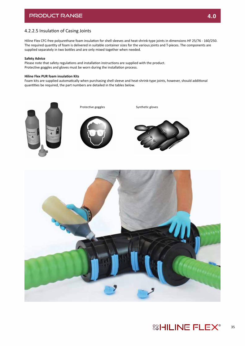
4.2.2.5 Insulation of Casing Joints
Hiline Flex CFC-free polyurethane foam insulation for shell sleeves and heat-shrink-type joints in dimensions HF 25/76 - 160/250.The required quantity of foam is delivered in suitable container sizes for the various joints and T-pieces. The components are supplied separately in two bottles and are only mixed together when needed.
Safety AdvicePlease note that safety regulations and installation instructions are supplied with the product.Protective goggles and gloves must be worn during the installation process.
HilineFlexPURfoaminsulationKitsFoam kits are supplied automatically when purchasing shell sleeve and heat-shrink-type joints, however, should additional quantities be required, the part numbers are detailed in the tables below.
Synthetic glovesProtective goggles
35

4.3 TERMINATIONS4.3.1.1 Building Entry (wall opening)
Wall opening
Core bores
Outer casing L min H min
Ø D
mm mm mm
76 450 250
91 500 250
111 500 300
126 550 300
142 600 350
162 650 350
182 670 380
202 720 400
250 810 450
Outer casing A D1
Ø D
mm mm mm
76 210 180
91 230 180
111 250 230
126 270 230
142 290 230
162 310 280
182 330 280
202 400 350
250 420 380
PEX-LOK connection piece: see sheet HF 4.2.1.4
End cap:see sheet HF 4.3.2
Wall sealing ring: see sheet HF 4.3.3
Hiline Flex pipe;
see sheets HF 4.1.1
D
approx. 80 mm
80 mm
80 80100D D
L
H
Dimensions in mm
min. 30
A
D1
Dimensions in mm
PRODUCT RANGE 4.0
36

PRODUCT RANGE 4.0
4.3.1.2 Building Entry (core drilled)
Core bores/cement pipe liners
Wall penetration
PEX-LOK connection piece:see sheet HF 4.2.1.4
Core bores Outer casing D1 A
Ø D
mm mm mm
76 180 150
91 180 150
111 230 200
126 230 200
142 230 200
162 280 250
182 280 250
202 330 300
250 380 380
PEX-LOK connection piece:see sheet HF 4.2.1.4
End cap:see sheet HF 4.3.2
Hiline Flex pipe: see sheets HF 4.1.1
Seal set: see sheet HF 4.3.4
D
80 mm
min. 30
A
D1
Dimensions in mm
37

4.3.2 End Cap
Heat-shrinkable
Heat-Shrink End Caps LDPEEndCap(non-heat-shrinkable)
Type Dimensions Part No
HF UNO 25/76 HF.2576.HSECU
HF UNO 32/76 HF.3276.HSECU
HF UNO 40/91 HF.4091.HSECU
HF UNO 50/111 to 75/142 HF.5075111142.HSECU
HF UNO 90/162 HF.90162.HSECU
HF UNO 110/162 to 140/202 HF.110140162202.HSECU
HF UNO 160/250 HF.160250.HSECU
HF DUO 2x25/91 HF.252591.HSECD
HF DUO 2x32/111 to 2x40/126 HF.3240111126.HSECD
HF DUO 2x50/162 HF.5050162.HSECD
HF DUO 2x63/182 HF.6363182.HSECD
Heat-shrink end cap, UNO LDPE end cap, UNO
Heat-shrink end cap, DUO LDPE End cap, DUO
LDPE end caps are suitable for dry areas only.
PRODUCT RANGE 4.0
Type Dimensions Part No
HF UNO 25/76 HF.2576.ECU
HF UNO 32/76 HF.3276.ECU
HF UNO 40/91 HF.4091.ECU
HF UNO 50/111 HF.50111.ECU
HF UNO 63/126 HF.63126.ECU
HF UNO 75/142 HF.75142.ECU
HF UNO 90/126 HF.90162.ECU
HF UNO 110/162 HF.110162.ECU
HF UNO 110/182 HF.110182.ECU
HF UNO 125/182 HF.125182.ECU
HF DUO 2x25/91 HF.252591.ECD
HF DUO 2x32/111 HF.3232111.ECD
HF DUO 2x40/126 HF.4040126.ECD
HF DUO 2x50/162 HF.5050162.ECD
HF DUO 2x63/182 HF.6363182.ECD
Push-fit
38

PRODUCT RANGE 4.0
4.3.3 Wall Sealing Ring
Hiline Flex UNO
Building entry (see sheet HF 4.3.1.1)
Outer casing pipe diameter Neoprene wall sealing ring Part No
ØD1,inner ØD2,outer
mm mm mm
76 74 118 HF.76.WSRN
91 88 133 HF.91.WSRN
111 107 153 HF.111.WSRN
126 122 168 HF.126.WSRN
142 137 183 HF.142.WSRN
162 155 203 HF.162.WSRN
182 175 223 HF.182.WSRN
202 195 230 HF.202.WSRN
250 243 290 HF.250.WSRN
Ø D
2
Ø D
1
50Dimensions in mm
For wall openings
39

4.3.4WallSeal(compressiontype)
For core bores/cement liner pipes
Standard Withadditionalcentringring
CoreboresPerfect bores are required for installation. As hairline cracks may be present in the concrete or result from drilling, it is advisable to seal the entire length of the borehole with suitable sealant (such as AQUAGARD). Tightness can only be guaranteed if this recommendation is followed.
1: Hiline Flex district heating pipe2: Seal set, single-seal 1 x 40 mm, Shore hardness D 353: Seal set, double-seal* 2 x 40 mm, Shore hardness D 354: Liner pipe: made of fibre cement or coated core bore
* Suitable for pressure from water up to 0.5 bar
Building entry (see sheet HF 4.3.1.2)
Outer Casing Pipe Linerpipe,corebore Seal set Corebore Part No
Ø D1 Ø D2 Ø inner Ø
mm mm mm mm
76 150 78 - 85 150 HF.76.WSRC
91 150 86 - 94 150 HF.91.WSRC
111 200 105 - 115 200 HF.111.WSRC
126 200 125 - 135 200 HF.126.WSRC
142 200 137 - 145 200 HF.142.WSRC
162 250 157 - 165 250 HF.162.WSRC
182 250 180 - 190 250 HF.182.WSRC
202 300 198 - 207 300 HF.202.WSRC
250 350 250 - 259 350 HF.250.WSRC
Out
er s
ide
of
base
men
t
3
4
1
D1 D2
Out
er s
ide
of
base
men
t
2 3
4
1
D1 D2
Inne
r sid
e of
base
men
t
Inne
r sid
e of
base
men
t
PRODUCT RANGE 4.0
40

4.3.5 Building Entry Bends
Heating 6 bar, UNO and DUO
Bend, 90°Dimensions: HF 25/76 - 125/182
Bend, 90° Steel with welded-on PEX-LOK compression couplingDimensions: HF 140/202 - 160/250
Hiline Flex DUO
Type PEX service pipe Outer casing Weight Part No
d D
mm mm kg/unit
25/ 76 25 75 2.30 HF.2576.LPU
32/ 76 32 75 2.50 HF.3276.LPU
40/ 91 40 90 3.47 HF.4091.LPU
50/111 50 110 4.92 HF.50111.LPU
63/126 63 125 6.50 HF.63126.LPU
75/142 75 140 8.47 HF.75142.LPU
90/162 90 160 11.40 HF.90162.LPU
110/162 110 160 14.23 HF.110162.LPU
110/182 110 180 16.19 HF.110182.LPU
125/182 125 180 17.20 HF.125182.LPU
140/225 140 225 40.95 HF.140202.LPU
160/250 160 250 58.40 HF.160250.LPU
Type PEX service pipe Outer casing Weight Part No
d D
mm mm kg/unit
25 + 25/ 91 2 x 25 90 4.32 HF.252591.LPD
32 + 32/111 2 x 32 110 4.67 HF.3232111.LPD
40 + 40/126 2 x 40 125 7.42 HF.4040126.LPD
50 + 50/162 2 x 50 160 9.90 HF.5050162.LPD
63 + 63/182 2 x 63 180 13.96 HF.6363182.LPD
1114
1114
Dimensions in mm
Please Note: Hiline Flex pre-insulated House Entry bends in dimensions 140/202 up to 160/250 are constructed with pre-insulated steel with pre-installed PEX-LOK compression connections as detailed in section 4.2.1.4. These fittings are also Steel grade St 37.0 P235GH TC1 - Coated with heavy-duty corrosion inhibiting compound Ardrox AV15.
PRODUCT RANGE 4.0
Hiline Flex UNO
41
UNO
A
1100
1600
250
250
250
DUOHorizontal
DUOVertical

PRODUCT RANGE 4.0
4.4 ACCESSORIES
4.4.1DistributionChambers Dimensions HF 25/76 - 125/182
Distribution chamber for all joints.The distribution chamber is used to cover and protect completed HiLine Flex pipe joints, shut-off valves or junction branches.The distribution chamber is a watertight structure made of polyethylene; its multi-functional design makes it possible touse one chamber type for all pipe dimensions.
* with additional centring ring
Diameter(mm) Part No
76 HF.76.ES-
91 HF.91.ES-
111 HF.111.ES-
126 HF.126.ES-
142 HF.142.ES-
162 HF.162.ES-
182 HF.182.ES-
Chamber 25/76 to 125/182 HF.CHAMBER
145
270
130
200
8
120120
120360
800
Ø206
Ø166
Ø 136
Ø1040
475
Dimensions in mm
HeatShrinkEntrySealforChamberExit
42

Diameter(mm) Part No
76 HF.76.ES-
91 HF.91.ES-
111 HF.111.ES-
126 HF.126.ES-
142 HF.142.ES-
162 HF.162.ES-
182 HF.182.ES-
Chamber 25/76 to 125/182 HF.CHAMBER
4.4.2ProtectiveConcretePlate
For distribution chamber
Schematic diagram showing installation of cover plate
LoadThe cover plate has to be used wherever there might be public traffic and for low-depth installations. The maximum load per unit of area must not exceedq = 153 kN/m² (SLW 60 to DIN 1055).InstallationmethodCorrect installation of the sand must beensured so that the plate can perform itsfunction as a load shield for the inspectionchamber. A Proctor density of dpr = 96 %should be the target for compaction.For subsequent work on the inspectionchamber, the cover plate has lifting eyes.After completing the work and refilling thepit, make sure that the infill between theinspection chamber and concrete slabs isrestored correctly.Filling/insulationmaterialAlthough not essential, to minimise heat loss from the chamber, it can be filled with insulation material such as mineral wool or polystyrene granules. Alternatively, bare pipes can be lagged conventionally.NoteThe plate must be located so thatit completely covers the chamber below(see illustration).
200m
m
Cover p
late
1.2m square
Inspection chamber
Sand, compacted
Inspection chamber
800
500
1,33
094
020
0
PRODUCT RANGE 4.0
Dimensions in mm
43
PRODUCT RANGE 4.0
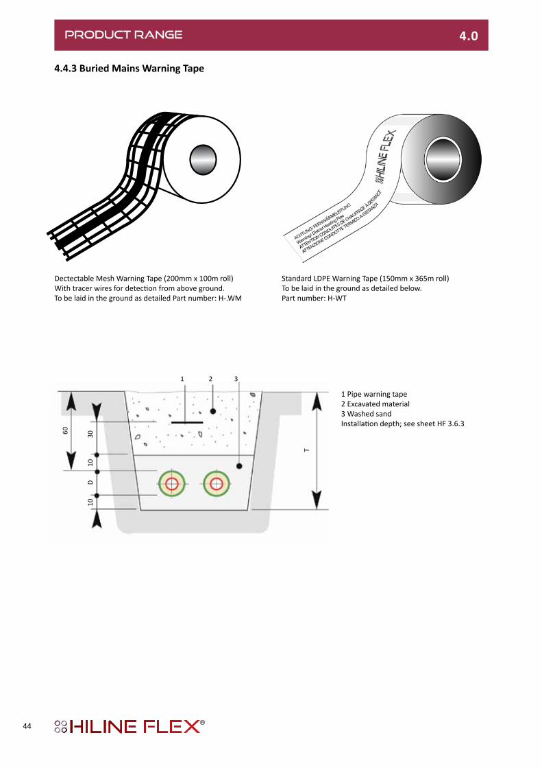
4.4.3 Buried Mains Warning Tape
1 Pipe warning tape2 Excavated material3 Washed sandInstallation depth; see sheet HF 3.6.3
1 2 3
60 3010
D10
T
Standard LDPE Warning Tape (150mm x 365m roll)To be laid in the ground as detailed below.Part number: H-WT
Dectectable Mesh Warning Tape (200mm x 100m roll)With tracer wires for detection from above ground.To be laid in the ground as detailed Part number: H-.WM
44
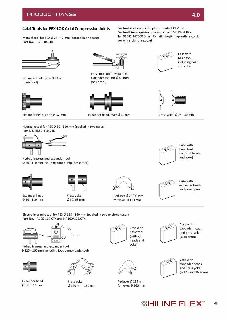
4.4.4 Tools for PEX-LOK Axial Compression Joints
Manual tool for PEX Ø 25 - 40 mm (packed in one case)Part No. HF.25-40.CTK
Expander tool, up to Ø 32 mm(basic tool)
Press tool, up to Ø 40 mmExpander tool for Ø 40 mm(basic tool)
Case with basic toolincluding head and yoke
Expander head, up to Ø 32 mm Expander head, over Ø 40 mm Press yoke, Ø 25 - 40 mm
Hydraulic tool for PEX Ø 50 - 110 mm (packed in two cases)Part No. HF.50-110.CTK
Hydraulic press and expander toolØ 50 - 110 mm including foot pump (basic tool)
Case with basic tool(without heads and yoke)
Expander headØ 50 - 110 mm
Press yokeØ 50, 63 mm
Reducer Ø 75/90 mmfor yoke, Ø 110 mm
Case with expander headsand press yoke
Electro-hydraulic tool for PEX Ø 125 - 160 mm (packed in two or three cases)Part No. HF.125-160.CTK and HF.160/125.CTK
Hydraulic press and expander toolØ 125 - 160 mm including foot pump (basic tool)
Case with basic tool(without heads and yoke)
Expander headØ 125 - 160 mm
Press yokeØ 140 mm, 160 mm
Reducer Ø 125 mmfor yoke, Ø 160 mm
Case with expander heads and press yoke.(ø 125 and 160 mm)
PRODUCT RANGE 4.0
Fortoolsalesenquiries: please contact CPV Ltd Fortoolhireenquiries:please contact JMS Plant Hire Tel. 01582 467000 Email: E-mail: [email protected]
Case with expander headsand press yoke.(ø 140 mm)
45

INSTALLATION 5.0
5.1 LOGISTICS AND PIPE COIL HANDLING
5.1.1Transportation
The load must be secured with appropriate method to avoid shifting during transportation. Any load-securing methods must not damage the outer casing – so 50mm-wide nylon webbing straps must be used.
5.1.2Lifting
When lifting, care must be taken to avoid damaging the outer casing from point loads. If using fork lift or tele-handler, suitable fork extensions or attachments must be used with radii to protect the pipe casing. Ensure that the coil is secured to avoid it slipping off.
If lifting by another means – such as a crane – 50mm-wide nylon webbing straps must be used. Rope must not be used for this purpose.
Make sure that the coil is lifted well-clear of the ground to avoid damage from obstacles and being dragged.
5.1.3 Site Storage
It is recommended that pipe coils are stored flat on wooden supports. As with transportation, the area must be free of sharp objects that could damage the outer casing. If coils are storedvertically,theymustbechocked to prevent rolling.
46
5.1.1PipeCoils(continued)
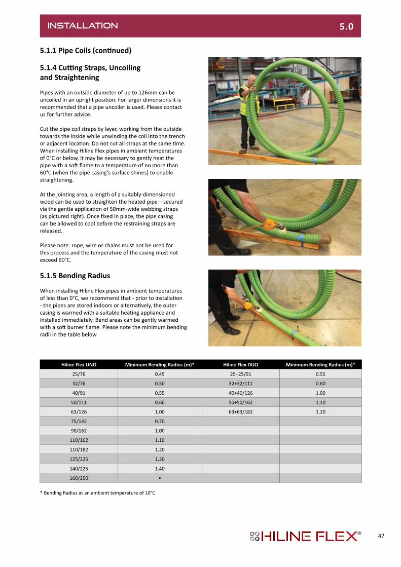
5.1.4CuttingStraps,Uncoilingand Straightening
Pipes with an outside diameter of up to 126mm can be uncoiled in an upright position. For larger dimensions it is recommended that a pipe uncoiler is used. Please contact us for further advice.
Cut the pipe coil straps by layer, working from the outside towards the inside while unwinding the coil into the trench or adjacent location. Do not cut all straps at the same time. When installing Hiline Flex pipes in ambient temperatures of 0°C or below, it may be necessary to gently heat the pipe with a soft flame to a temperature of no more than 60°C (when the pipe casing’s surface shines) to enable straightening.
At the jointing area, a length of a suitably-dimensioned wood can be used to straighten the heated pipe – secured via the gentle application of 50mm-wide webbing straps (as pictured right). Once fixed in place, the pipe casing can be allowed to cool before the restraining straps are released.
Please note: rope, wire or chains must not be used for this process and the temperature of the casing must not exceed 60°C.
5.1.5 Bending Radius
When installing Hiline Flex pipes in ambient temperatures of less than 0°C, we recommend that - prior to installation - the pipes are stored indoors or alternatively, the outer casing is warmed with a suitable heating appliance and installed immediately. Bend areas can be gently warmed with a soft burner flame. Please note the minimum bending radii in the table below.
Hiline Flex UNO MinimumBendingRadius(m)* Hiline Flex DUO MinimumBendingRadius(m)*
25/76 0.45 25+25/91 0.55
32/76 0.50 32+32/111 0.60
40/91 0.55 40+40/126 1.00
50/111 0.60 50+50/162 1.10
63/126 1.00 63+63/182 1.20
75/142 0.70
90/162 1.00
110/162 1.10
110/182 1.20
125/225 1.30
140/225 1.40
160/250 •
* Bending Radius at an ambient temperature of 10°C
INSTALLATION 5.0
47

INSTALLATION 5.0
5.2 PIPE LAYING
5.2.1 Trench Dimensions
Please refer to Section 3.6 regarding design considerations for trench dimensions – such as traffic loadings and special ground conditions.
1: Pipe warning tape; see sheet HF 4.4.32: Excavated material3: Washed sand
Trenchprofile,2HilineFlexpipes
UNO
SLW 30 300 kN total load as per DIN 1072; if subject to higher traffic loads (e.g. SLW 60), a load-distributing superstructure as per RStO75 is required. With no traffic load, the minimum trench depth T can be reduced by 20 cm.
Outer casing Width Depth Minimum
Ø D B T Bending radius
mm cm cm m
76 45 80 0.7
91 50 80 0.8
111 55 85 0.9
126 55 85 1.0
142 60 85 1.1
162 65 90 1.2
182 70 95 1.4
202 75 95 1.4
250 80 100 -
1 2 3
1010
3060
D
T
10 10 10D DB
Outer casing Width Depth Minimum
Ø D B T Bending radius
mm cm cm m
91 30 80 0.8
111 30 85 0.9
126 35 85 1.0
142 35 85 1.1
162 35 90 1.2
182 38 95 1.4
DUO
1010
3060
D
T
D10 10B
1 2 3
Dimensions in cm
Trenchprofile,4HilineFlexpipes
Installationdepth:Max. installation depth: 2.6 mOur approval is required for installation at greater depths.
T
10 10 10 10 10D D D DB (4 x D + 5
x 10)
1010
30D
60
1 2 3
10 10 10D D
105
1030
DD
60
T
B
1 2 3
Dimensions in cm
Trenchprofile,4HilineFlexpipes
48
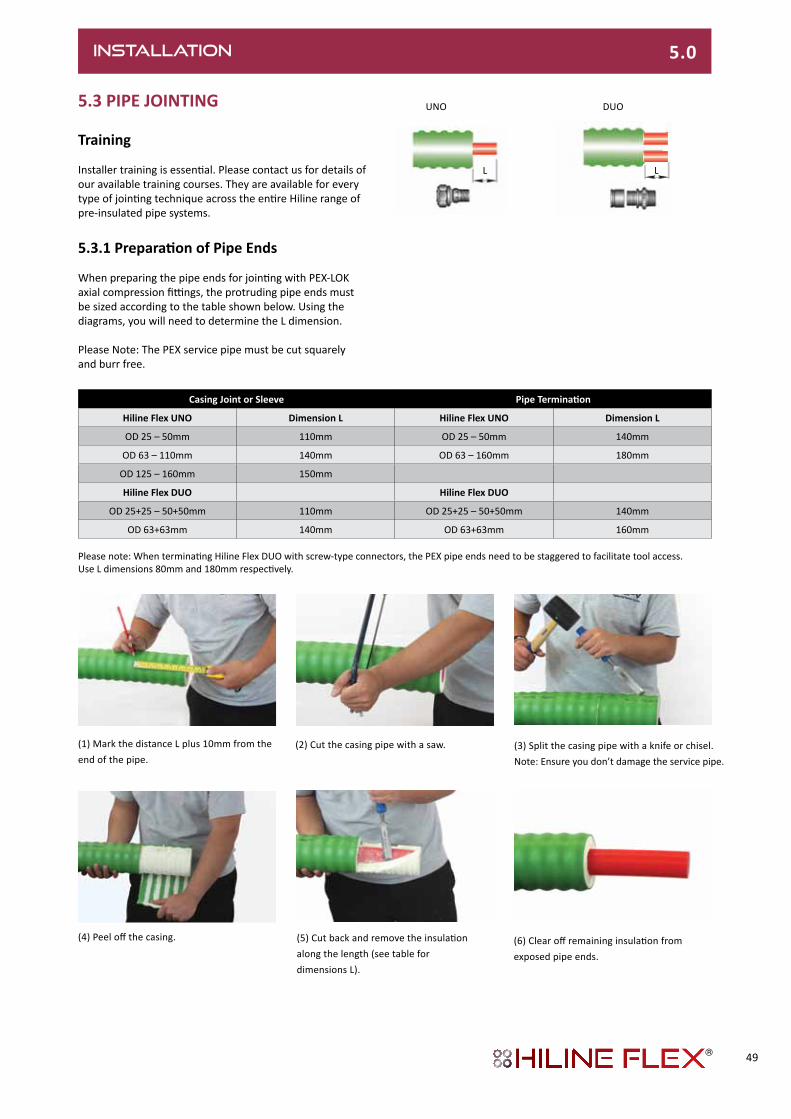
5.3 PIPE JOINTING
Training
Installer training is essential. Please contact us for details of our available training courses. They are available for every type of jointing technique across the entire Hiline range of pre-insulated pipe systems.
5.3.1PreparationofPipeEnds
When preparing the pipe ends for jointing with PEX-LOK axial compression fittings, the protruding pipe ends must be sized according to the table shown below. Using the diagrams, you will need to determine the L dimension.
Please Note: The PEX service pipe must be cut squarely and burr free.
(1) Mark the distance L plus 10mm from the end of the pipe.
(2) Cut the casing pipe with a saw. (3) Split the casing pipe with a knife or chisel. Note: Ensure you don’t damage the service pipe.
(4) Peel off the casing. (5) Cut back and remove the insulation along the length (see table for dimensions L).
(6) Clear off remaining insulation from exposed pipe ends.
UNO
L
Casing Joint or Sleeve PipeTermination
Hiline Flex UNO Dimension L Hiline Flex UNO Dimension L
OD 25 – 50mm 110mm OD 25 – 50mm 140mm
OD 63 – 110mm 140mm OD 63 – 160mm 180mm
OD 125 – 160mm 150mm
Hiline Flex DUO Hiline Flex DUO
OD 25+25 – 50+50mm 110mm OD 25+25 – 50+50mm 140mm
OD 63+63mm 140mm OD 63+63mm 160mm
INSTALLATION 5.0
DUO
L
Please note: When terminating Hiline Flex DUO with screw-type connectors, the PEX pipe ends need to be staggered to facilitate tool access. Use L dimensions 80mm and 180mm respectively.
49

INSTALLATION 5.0
5.3.2ServicePipeJointing
Before starting this process, please ensure that the pipe ends have been prepared as detailed in section 5.3.1. If using shell sleeves it is important that the casing joint sealing rings are located on all ends of the pipe outer casing (see section 5.3.3.2). If joining the casing with heat-shrink joints, please ensure that the oversleeve and heat shrinkable bands are in place (refer to section 5.3.4). Please Note: Hiline Flex DUO has one of its two service pipes marked with a blue stripe to ease identification of flow and return.
(1) The PEX-LOK compression sleeve can be slid onto the prepared pipe ends. The square end faces the insulation and the chamfered end faces towards the joint.
(2) Expand the pipe end twice – offset by approximately 30°. Ensure that the compression sleeve is slid well back from the area being expanded.
(3) Insert the PEX-LOK fitting (tee, elbow or straight coupling). Locate the clamping jaws on the tool and clamp onto the joint. For dimensions over 40mm, a lubricant of petroleum jelly must must be used in the area of the compression sleeve.
(4) If required for additional compression sleeve connection, a recess can be cut out to allow room for the clamping tool (see table below).
(5) Clamp the second pipe. If this is a straight or 90 degree coupling, then the connection is completed.
(6) If creating a Tee-branch connection, clamp the third pipe. It may be necessary to make room for the clamping tool as discussed in step (4) above.
Service Pipe OD Length L Tool A1 or M1 Length L Tool G1
20-40mm 170mm -
40-110mm - 270mm
L
50

5.3.3JointingwithShellSleeves
5.3.3.1 Components List
The components for the Shell Sleeve casing joint system are detailed below.
Site Safety and COSHHPlease ensure that all instructions are followed carefully and that the correct site safety equipment such as gloves and eye protection are worn at the appropriate times. COSHH data sheets are available on request for adhesives and foam insulation component liquids.
1. Upper shell half with plug holes1. Lower shell half without plug holes2. Clamps blue3. Plugs blue4. Sealing rings5. Glue6. Foam set7. Instruction manual
Importantinformationonhandlingthisproductsafelyand correctly• Never expose the foam (6) glue (5) or shell (1) to sunlight or heat sources! Store in a cool and dry place.• Always install sealing rings (4) before fittings (sealing rings cannot be installed afterwards.)• Always make sure pipes are clean and adhesion surfaces on both shells are free of grease.• Wear safety goggles and gloves when gluing and working with foam.• Only use the correctly-sized foam kit for the respective joint.
2 3
4 5 6 7
1
INSTALLATION 5.0
51

INSTALLATION 5.0
5.3.3.2 Preparation for Jointing
PositioningEnsure pipes are positioned as per the pictures – according to the type of joint – Tee, Straight or 90-degree bend coupling.
Straight coupling
Tee
Bend
Sealing RingsPull the sealing rings over the pipe ends – ensuring that the sealing ridges are pointing outwards (away from the jointing area).
52

5.3.3.3 Fitting the Shell Sleeve Joint
(1) Position the lower shell sleeve and ensure that the sealing rings are precisely located (see picture). PLEASE NOTE: The lower shell does not have the plug holes.
(2) Clean all of the joining surfaces of the two shell halves to ensure that they are free from dirt and grease.
(3) Apply a continuous line of adhesive (4mm wide) to the jointing surface of the lower shell (as pictured).
(4) Place the upper shell on top of the lower shell (as pictured). (5) Immediately apply all of the clamps to the locations provided and allow the adhesive to harden for at least 20 minutes.
INSTALLATION 5.0
53

INSTALLATION 5.0
5.3.3.3 Fitting the Shell Sleeve Joint (continued)
(6) Prepare the two-part PUR foam kit in accordance with the instructions supplied, then pour the mixed foam liquid into the shell through the filling hole.PLEASE NOTE: Safety advice must be adhered to when dealing with two-part foam.
(7) Immediately after pouring foam liquid, seal both openings with the plugs supplied – making a rotary 1/4 clockwise turn.
(8) After at least five minutes has elapsed, seal the openings with the rubber stoppers (see picture).
5.3.4JointingwithHeat-ShrinkCasingJoint
Components List
• HDPE oversleeve materials (packed in white polythene) x 1 • Heat shrinkable bands x 2 • The components A and B forming PUR foam, batched in separate bottles • Vent plugs x 2 • Welded plugs x 2
Please Note: Specialist training is required to install this type of joint. Please contact CPV for details
PLEASE NOTE: The heat-shrink joint and foam must be stored at a temperature below 25°C and kept out of direct sunlight. The installation of this joint must only be carried out in dry conditions and when ambient temperatures are over 5°C. Failure to comply with this may affect the integrity of the joint.
54
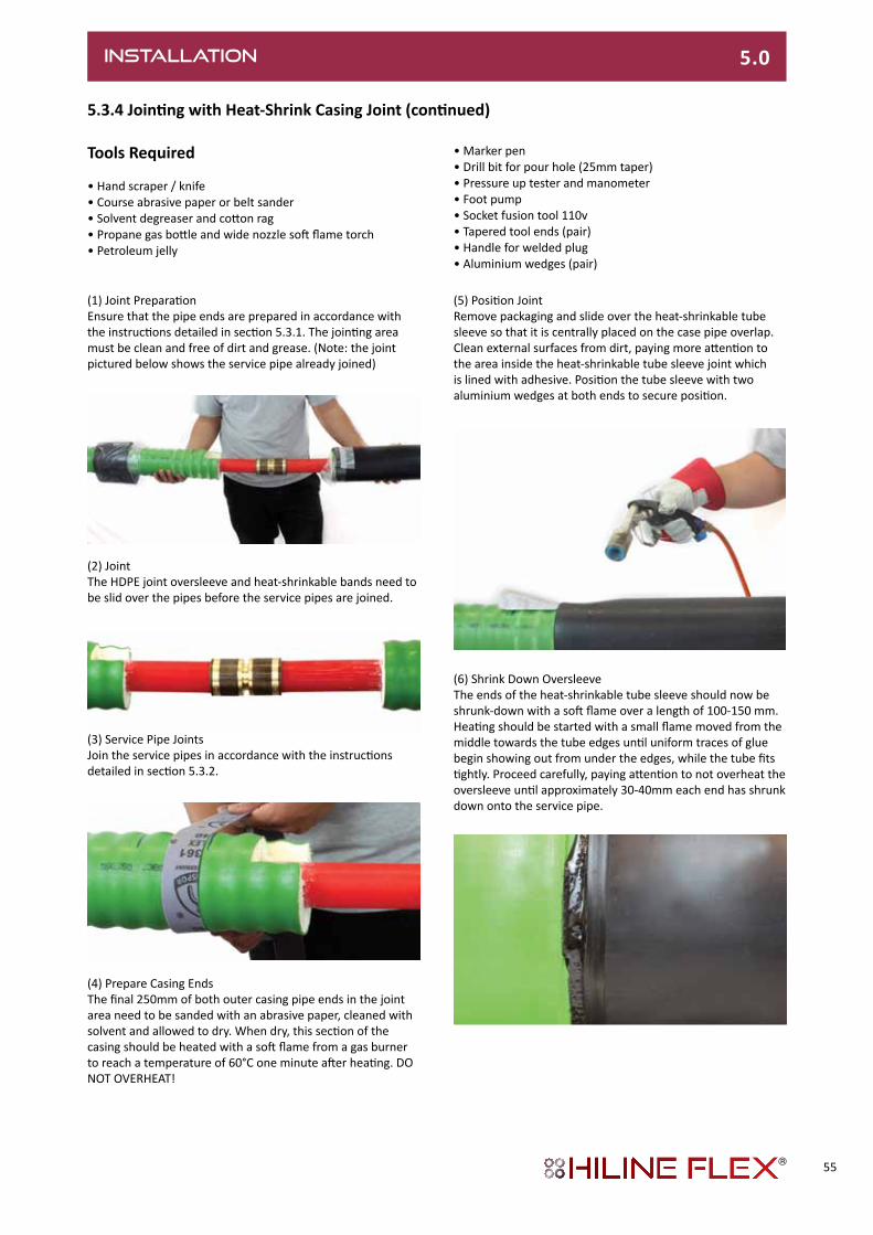
(1) Joint PreparationEnsure that the pipe ends are prepared in accordance with the instructions detailed in section 5.3.1. The jointing area must be clean and free of dirt and grease. (Note: the joint pictured below shows the service pipe already joined)
5.3.4JointingwithHeat-ShrinkCasingJoint(continued)
(5) Position JointRemove packaging and slide over the heat-shrinkable tube sleeve so that it is centrally placed on the case pipe overlap. Clean external surfaces from dirt, paying more attention to the area inside the heat-shrinkable tube sleeve joint which is lined with adhesive. Position the tube sleeve with two aluminium wedges at both ends to secure position.
(2) JointThe HDPE joint oversleeve and heat-shrinkable bands need to be slid over the pipes before the service pipes are joined.
(3) Service Pipe JointsJoin the service pipes in accordance with the instructions detailed in section 5.3.2.
(4) Prepare Casing EndsThe final 250mm of both outer casing pipe ends in the joint area need to be sanded with an abrasive paper, cleaned with solvent and allowed to dry. When dry, this section of the casing should be heated with a soft flame from a gas burner to reach a temperature of 60°C one minute after heating. DO NOT OVERHEAT!
(6) Shrink Down OversleeveThe ends of the heat-shrinkable tube sleeve should now be shrunk-down with a soft flame over a length of 100-150 mm. Heating should be started with a small flame moved from the middle towards the tube edges until uniform traces of glue begin showing out from under the edges, while the tube fits tightly. Proceed carefully, paying attention to not overheat the oversleeve until approximately 30-40mm each end has shrunk down onto the service pipe.
INSTALLATION 5.0
Tools Required
• Hand scraper / knife • Course abrasive paper or belt sander • Solvent degreaser and cotton rag • Propane gas bottle and wide nozzle soft flame torch • Petroleum jelly
• Marker pen • Drill bit for pour hole (25mm taper) • Pressure up tester and manometer • Foot pump • Socket fusion tool 110v • Tapered tool ends (pair) • Handle for welded plug • Aluminium wedges (pair)
55
INSTALLATION 5.0
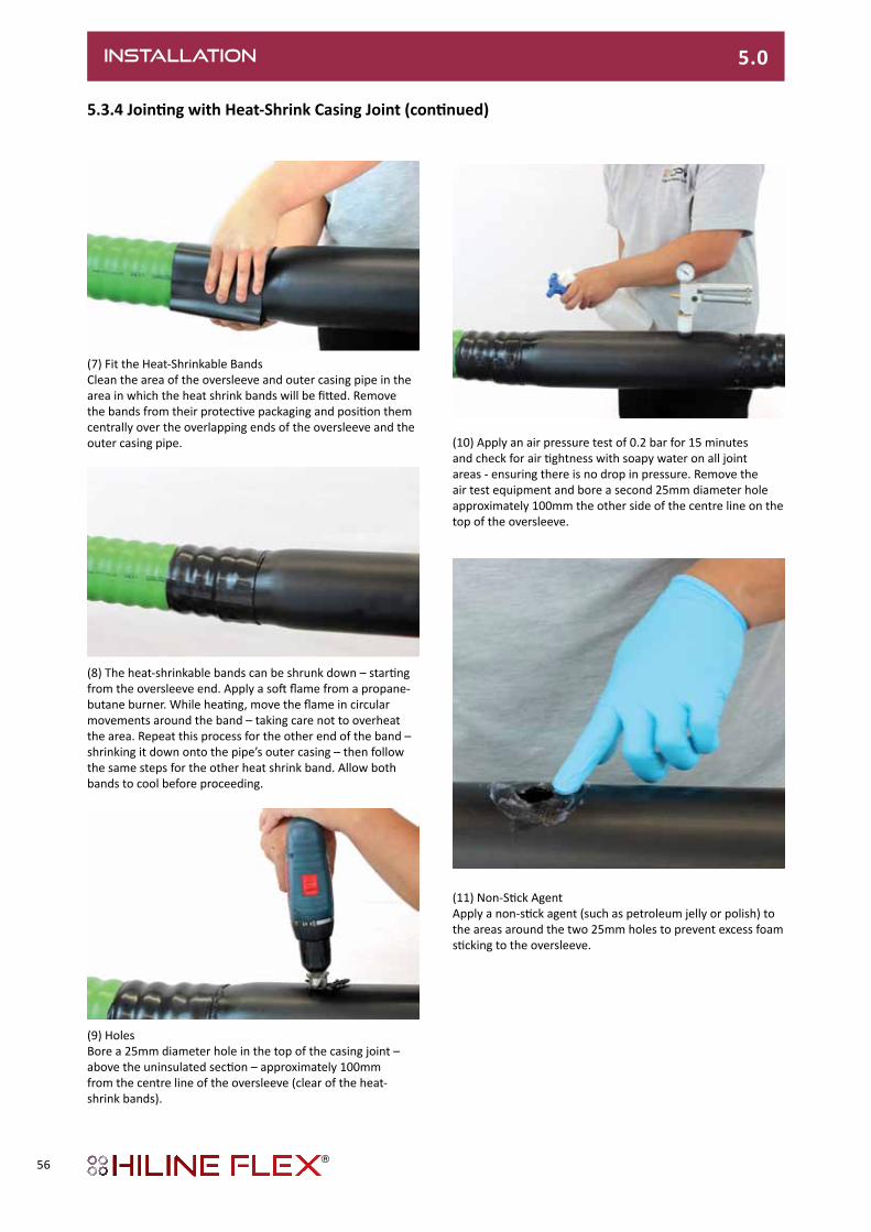
(10) Apply an air pressure test of 0.2 bar for 15 minutes and check for air tightness with soapy water on all joint areas - ensuring there is no drop in pressure. Remove the air test equipment and bore a second 25mm diameter hole approximately 100mm the other side of the centre line on the top of the oversleeve.
5.3.4JointingwithHeat-ShrinkCasingJoint(continued)
(7) Fit the Heat-Shrinkable BandsClean the area of the oversleeve and outer casing pipe in the area in which the heat shrink bands will be fitted. Remove the bands from their protective packaging and position them centrally over the overlapping ends of the oversleeve and the outer casing pipe.
(8) The heat-shrinkable bands can be shrunk down – starting from the oversleeve end. Apply a soft flame from a propane-butane burner. While heating, move the flame in circular movements around the band – taking care not to overheat the area. Repeat this process for the other end of the band – shrinking it down onto the pipe’s outer casing – then follow the same steps for the other heat shrink band. Allow both bands to cool before proceeding.
(9) HolesBore a 25mm diameter hole in the top of the casing joint – above the uninsulated section – approximately 100mm from the centre line of the oversleeve (clear of the heat-shrink bands).
(11) Non-Stick AgentApply a non-stick agent (such as petroleum jelly or polish) to the areas around the two 25mm holes to prevent excess foam sticking to the oversleeve.
56

5.3.4JointingwithHeatShrinkCasingJoint(continued)
(14) Using a pre-heated electric fusion welding tool, the welded plugs need to be put into the heater, with the male end of the heater placed into the joints filler hole. When heated, the plug can be pressed into place in the hole with hand pressure until there’s a visible 2mm bead melt on both the plug and hole. Repeat this process for the second hole.
(12) Foam InsulationEnsuring that the joint area has cooled to at least 40°C, pour the mixed foam liquid into one of the two holes. Make sure that the mixture is to the correct volumes following the supplied instructions. The reaction time for the mixed liquids is approximately 50 seconds at an ambient temperature of 20°C
Once poured, both holes need to be blocked with venting plugs down to the first notch. When foam appears in the plugs’ vent holes, the plugs can be driven into place with a hammer.
(13) Sealing PlugsOnce the foam has hardened, the excess foam can be cleaned away and the areas around the vent plugs degreased. To seal the holes, the vent plugs need to be removed and the openings thoroughly cleaned with a scraper and abrasive paper.
When completed and cooled, the plug should protrude no more than 1-2mm.
INSTALLATION 5.0
Excess bead can be trimmed if required.
57

5.4 PIPE TERMINATONS
5.4.1 End Caps
IntroductionThere are two types of end cap available to protect the exposed ends of the insulation. A heat-shrink type for areas containing moisture and slide-on LDPE type for general protection and aesthetics. Before fitting, the pipe ends must be stripped back to the dimensions detailed in section 5.3.1.
Heat-Shrink End Caps(1) The ends of the outer casing pipe need to be roughened up with abrasive paper and cleaned with solvent.(2) Pre-heat the heat shrink area to over 60°C. Use a temperature indicator strip to check this temperature.(3) Slide on the end cap and shrink-down with a soft flame until adhesive appears on all edges of the end cap.
Push-Fit End CapsAs its name would suggest, simply prepare the pipe ends and push on the end cap.
Hiline Flex UNO Hiline Flex DUO
Heat-shrink end cap, UNO Push-fit LDPE End cap, UNO
Heat-shrink end cap, DUO Push-fit LDPE End cap, DUO
Type
25/ 76
32/ 76
40/ 91
50/111
63/126
75/142
90/162
110/162
110/182
125/182
140/202
160/250
Type
25 + 25/ 91
32 + 32/111
40 + 40/126
50 + 50/162
63 + 63/182
INSTALLATION 5.0
58

INSTALLATION 5.0
5.4.2 Wall Entry Sleeves
5.4.2.1 Wall Sealing Ring
Wall sealing rings are used to seal the building against the ingress of moisture when using core-drilled holes. The diagrams on the following page detail the correct configuration for this termination.
For wall openings
Hiline Flex UNO & DUO
Outer casing pipe diameter
Neoprene wall sealing ring
ØD1,inner ØD2,outer
mm mm mm
76 74 118
91 88 133
111 107 153
126 122 168
142 137 183
162 155 203
182 175 223
202 195 230
250 243 290
Building entry (see sheet HF 4.3.1.1)
Ø D
2
Ø D
1
50
Dimensions in mm
59

5.4.2.1 Wall Sealing Ring
Wall penetration
Wall opening
Core bores
Outer casing L min H min
Ø D
mm mm mm
76 450 250
91 500 250
111 500 300
126 550 300
142 600 350
162 650 350
182 670 380
202 720 400
250 810 450
Outer casing A D1
Ø D
mm mm mm
76 210 180
91 230 180
111 250 230
126 270 230
142 290 230
162 310 280
182 330 280
202 400 350
250 420 380
End cap:
see sheet HF 4.3.2Wall sealing ring: see sheet HF 4.3.3
Hiline Flex pipe;
see sheets HF 4.1.1
D
approx. 80 mm
80 mm
80 80100D D
L
H
Dimensions in mm
min. 30
A
D1
Dimensions in mm
INSTALLATION 5.0
60

INSTALLATION 5.0
5.4.2.2. Wall Seal (compression type)
Core bores/cement liner pipes
Standard With additional centring ring
Core boresPerfect bores are required for installation. As hairline cracks may be present in the concrete or result from drilling, it is advisable to seal the entire length of the borehole with suitable sealant (such as AQUAGARD).Tightness can only be guaranteed if this recommendation is followed.
1 Hiline Flex district heating pipe2 Seal set, single-seal1 x 40 mm, Shore hardness D 353 Seal set, double-seal*2 x 40 mm, Shore hardness D 354 Liner pipe: made of fibre cement or coated core bore
* Suitable for pressure from ground water up to 0.5 bar
Building entry (see sheet HF 4.3.1.2)
Outer Casing Linerpipe,corebore Seal set Corebore
Ø D1 Ø D2 Ø inner Ø
mm mm mm mm
76 150 78 - 85 150
91 150 86 - 94 150
111 200 105 - 115 200
126 200 125 - 135 200
142 200 137 - 145 200
162 250 157 - 165 250
182 250 180 - 190 250
202 300 198 - 207 300
250 350 250 - 259 350
Out
er s
ide
of
base
men
t
3
4
1
D1 D2
Out
er s
ide
of
base
men
t
23
4
D1 D2
Inne
r sid
e of
base
men
t
Inne
r sid
e of
base
men
t
61
1

5.4.2.2. Wall Seal (continued)
Wall penetration
Core bores Outer casing D1 A
Ø D
mm mm mm
76 180 150
91 180 150
111 230 200
126 230 200
142 230 200
162 280 250
182 280 250
202 330 300
250 380 350
PEX-LOK connection piece:
see sheet HF 4.2.1.4
End cap:
see sheet HF 4.3.2
Hiline Flex pipe:
see sheets HF 4.1.1
Seal set:
see sheet HF 4.3.4
D
80 mm
min. 30
A
D1
Dimensions in mm
INSTALLATION 5.0
62

INSTALLATION 5.0
5.4.3BuildingTermination
Shaft entry, fixed point forces
Connectionwithexternalthread
Fixed point forces occurring Hiline Flex heating, 6 bar Heating,6bar
PEX pipe L1
mm mm
25 260
32 260
40 270
50 270
63 320
75 320
90 330
110 340
125 340
160 340
Heating,6bar
PEX pipe L2
mm mm
25 250
32 250
40 260
50 270
63 310
75 310
90 310
110 310
125 310
140 340
160 340
Maximumfixedpointforcesoccurringperpipefor:
90°C,6bar 60°C,6bar
Type Fmax [N] Type Fmax [N]
25/ 76 925 25/ 76 755
32/ 76 1495 32/ 76 1225
40/ 91 2365 40/ 91 1940
50/111 3685 50/111 3015
63/126 5785 63/126 4740
75/142 8205 75/142 6720
90/162 11860 90/162 9720
110/182 17675 110/182 14480
125/182 22878 125/182 18745
140/202 28747 140/202 23553
160/250 37510 160/250 30730
Fixed point
PEX-LOK connecting
piece with external
thread: see sheet
HF 4.2.1.4 End cap:see sheet HF 4.3.2
Wall sealing ring:see sheet HF 4.3.3
Hiline Flex pipesee sheetsHF 4.1.1
*L1*80
approx. 80
max
. 100
Dimensions in mm
Connectionwithweldend
* Dimensions can be reduced by max. 60 mm if end cap is walled in.
Weld on
Install
PEX-LOK connecting
piece with weld end:
see sheet HF 4.2.1.4
Fixed pointEnd cap:
see sheet HF 4.3.2
approx. 80
*80
*L2
1
2
Dimensions in mm
HiLine Flex
HiLine Flex
Hiline Flex
Hiline Flex
63
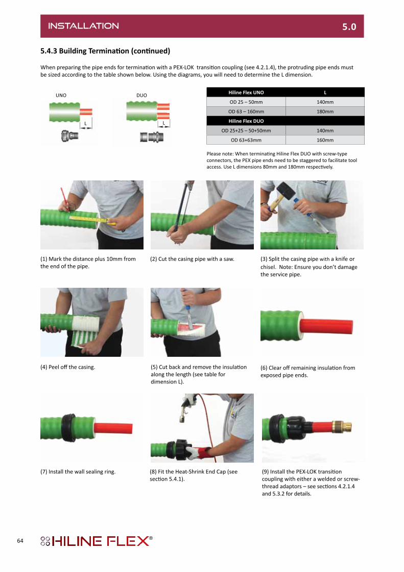
5.4.3BuildingTermination(continued)
When preparing the pipe ends for termination with a PEX-LOK transition coupling (see 4.2.1.4), the protruding pipe ends must be sized according to the table shown below. Using the diagrams, you will need to determine the L dimension.
(9) Install the PEX-LOK transition coupling with either a welded or screw-thread adaptors – see sections 4.2.1.4 and 5.3.2 for details.
(1) Mark the distance plus 10mm from the end of the pipe.
(2) Cut the casing pipe with a saw. (3) Split the casing pipe with a knife or chisel. Note: Ensure you don’t damage the service pipe.
(4) Peel off the casing. (5) Cut back and remove the insulation along the length (see table for dimension L).
(6) Clear off remaining insulation from exposed pipe ends.
(7) Install the wall sealing ring. (8) Fit the Heat-Shrink End Cap (see section 5.4.1).
Hiline Flex UNO L
OD 25 – 50mm 140mm
OD 63 – 160mm 180mm
Hiline Flex DUO
OD 25+25 – 50+50mm 140mm
OD 63+63mm 160mm
INSTALLATION 5.0
UNO
L
DUO
L
Please note: When terminating Hiline Flex DUO with screw-type connectors, the PEX pipe ends need to be staggered to facilitate tool access. Use L dimensions 80mm and 180mm respectively.
64

INSTALLATION 5.0
5.4.4ChamberTerminations
5.4.4.1 Dimensions HF 25/76 - 125/182
Distribution chamber for all jointsThe distribution chamber is used to cover and protect completed Hiline Flex pipe joints, shut-off valves or junction branches.The distribution chamber is a watertight structure made of polyethylene; its multi-functional design makes it possible touse one chamber type for all pipe dimensions (with the exception of dimensions 140 and 160mm).
* with additional centring ring
ØChamberexit Pipedimensions(outerdiameter)
Ø outer, 206 x 8 mm access for outer Ø Ø 182, 162*
Ø outer, 166 x 8 mm access for outer Ø Ø 142, 126*
Ø outer, 136 x 8 mm access for outer Ø Ø 111, 91*, 76*
Wall thickness approx. 8 mm
145
270
130
200
8
120120
120360
Ø 800
Ø 206
Ø166
Ø 136
Ø 1040
475
Dimensions in mm
65

5.4.4.2 Chamber Termination Procedure
For Dimensions 25/76 to 125/182mm
1
Ø13
6
Ø16
6
Ø20
6
2
3
Two-part reduction ring
4
(3) & (4) Where required, use a two-part reduction ring to ensure there’s a tight fit between the pipe’s outer casing and the pre-formed chamber inlet pipe.
(1) Cut the required pre-formed chamber access pipe end to suit the outer casing diameter of incoming Hiline Flex pipe.
(2) Insert the heat shrink bands over the ends of the pipe
INSTALLATION 5.0
66

INSTALLATION 5.0
5.4.4.2 Chamber Termination Procedure (continued)
(5) Make the required service pipe connections within the chamber.
(6) Fix the chamber’s lid – ensuring the flat seal is in place – using the M10 nuts and bolts (35 sets).
5 6
See HF installation instructions
Flat seal
29 x 12
M10s
7
Ø 1
69
Ø 2
36
8
(7) Having ensured that the joining area is clean and free of dirt, remove the packaging from the heat-shrink bands and slide them over the overlap between the Hiline Flex outer casing pipe and the chamber inlet pipe. Using a soft flame from a propane-butane burner, shrink the heat shrink bands down onto the joint area – taking care not to overheat the area.
67
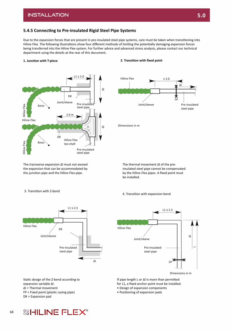
5.4.5ConnectingtoPre-insulatedRigidSteelPipeSystems
Due to the expansion forces that are present in pre-insulated steel pipe systems, care must be taken when transitioning into Hiline Flex. The following illustrations show four different methods of limiting the potentially damaging expansion forces being transferred into the Hiline Flex system. For further advice and advanced stress analysis, please contact our technical department using the details at the rear of this document.
1.JunctionwithT-piece 2.Transitionwithfixedpoint
The transverse expansion Δl must not exceed the expansion that can be accommodated by the junction pipe and the Hiline Flex pipe.
The thermal movement Δl of the pre-insulated steel pipe cannot be compensated by the Hiline Flex pipes. A fixed point must be installed.
3. Transition with Z-bend4. Transition with expansion bend
Static design of the Z-bend according to expansion variable Δl.Δl = Thermal movementFP = Fixed point (plastic casing pipe)DK = Expansion pad
If pipe length L or Δl is more than permitted for L1, a fixed anchor point must be installed. • Design of expansion components• Positioning of expansion pads
L1 ≤ 2.0
DK
Hiline Flex
Hili
ne F
lex
Hili
ne F
lex
Joint/sleeve Pre-insulated steel pipe
DK
Rmin
Rmin
2.0 m
Hiline Flex tee-shell
∆I∆I
Hiline Flex
Joint/sleeve Pre-insulated steel pipe
≤ 2.0
∆I
FP
Dimensions in m
L1 ≤ 2.5
DKHiline Flex
∆I
Pre-insulatedsteel pipe
Joint/sleeve
L1 ≤ 2.5
Hiline Flex
FP
Dimensions in m
Joint/sleeve
∆IL
INSTALLATION 5.0
Pre-insulated steel pipe
Pre-insulated steel pipe
68

COMMISSIONING 6.0
6.0 COMMISSIONING
6.1.0PressureTesting
All pipes and joints must be pressure tested before trenches are backfilled. It is recommended that, where possible, the pressure test is carried out before the outer casing joints are fitted to facilitate visual inspection of the service pipe jointing area.
6.1.1 Test Procedure with Water
Having inspected the pipe network for any signs of damage, the system must be flushed and clear of any dirt and debris that may have entered the service pipe during the installation process.
When full and all air has been vented, the system shall be pressurised to 6 bar or 1.5 times the operating pressure (use the greater of the two values). Having closed the isolation valves on the system, inspect the connections to ensure that there is no leakage.
Due to the flexible mechanical properties of the PE-Xa service pipe, the pressurisation process will need to be repeated a few times. The following steps must be followed and the pressures recorded on the Pressure Test Sheet (See HF 6.4).
Preliminary Test• System initial pressurisation • Time elapsed: 10min – re-pressurise to test pressure• Time elapsed: 20min - re-pressurise to test pressure• Time elapsed: 30min – record pressure• Time elapsed: 60min – record pressure. A fall in pressure of <0.6 bar is acceptable this stage. Main Test• Time elapsed: 180min – record pressure. A fall in pressure of <0.2 bar is acceptable.
NOTE: Check whole installation, particularly junction points, with regard to leak-tightness using a visual test. Water should not leak out at any point on the installation, particularly at the junction points. The maximum permissible operating pressure to DIN 16892/93 may not be exceeded during the test.
6.2.0 DrawingsIt is important to record the ‘as-installed’ pipe network dimensions in accordance with standard DIN 2425-2 and any other relevant standards as required by appropriate regulations for building services and buried utilities.
6.3 WATER TREATMENTAny water treatment used must be compatible with PE-Xa and the components of the axial compression jointing system. Please note that certain sizes of service pipe joints and pre-insulated fittings may contain steel components, so may need an appropriate water treatment to be in place.
69

6.4 PRESSURE TEST REPORT
COPY FORM
Pressure test sheet:Test in line with DIN 1988 Part 2Medium: Water
1.InstallationDetails
Building project:
Property owner:
Street / house number:
Postcode/town:
2. Preliminary Test
2.1 Test pressure: bar (recommended 1.5 times operating pressure)2.2 Recorded pressure after 10 min. bar (re-pressurise)2.3 Recorded pressure after 20 min. bar (re-pressurise)2.4 Recorded pressure after 30 min. bar2.5 Recorded pressure after 60 min. bar (permissible fall in pressure < 0.6 bar)
3. Main Test
3.1 Test pressure bar (result of the preliminary test as per point 2.5)3.2 Recorded pressure after 2 hours bar (permissible fall in pressure < 0.2 bar)3.3 Comments on test:
Check whole installation, particularly junction points, with regard to leak-tightness using a visual test. Water should not leak out at any point on the installation, particularly at the junction points. The maximum permissible operating pressure to DIN 16892/93 may not be exceeded during the test.
4.Confirmation
For the customer:
For the contractor:
Location: Date:
Attachments:
COMMISSIONING 6.0
70

APPENDIX
AboutCPVLtdFounded in 1948, and the first British company to manufacture pre-insulated pipe systems for district heating applications, CPV operates in a wide array of sectors, with products satisfying many applications. Our state-of-the-art production facility - based at the site of our headquarters near Romsey in Hampshire - is backed by a comprehensive selection of research, design, engineering, testing, quality, training and support services; ensuring the perfect marriage between our products and the applications they serve.
DistrictHeatingPipeSystemsWorld-class support Services
At CPV we pride ourselves by the way in which we support our customers – from the moment that they first contact us through to their long-term operation and maintenance of a pre-insulated pipe network. As manufacturer, it’s important to us to ensure that our systems deliver exceptional performance throughout their working life. Therefore, we have established an array of world-class support services that help our clients every step of the way.
Design and Stress AnalysisThere are many factors that will affect the long-term integrity of a pre-insulated pipe system. Correctly identifying and dealing with the potential for thermal expansion of the pipe system is a critical element of the design process and we employ state-of-the-art sisKMR specialist stress analysis software tools.
TrainingTraining installers, supervisors and maintenance operatives, our brand new training centre allows for not only the theory, but hands-on practical experience in the correct method for installing the Hiline pipe systems. In addition to this, we also offer training courses in the design, installation, commissioning and maintenance
of electronic surveillance systems – including the use of our own buried pipe network, on which we can simulate moisture faults as part of the practical training.
On-site Support ServicesWhether it’s on-site training, site supervision or specialist advice, support and maintenance – our engineers are at hand to provide customer support as and when required.
DrawingsWe can prepare detailed design drawings and as installed drawings that accurately record a completed system’s on-site dimensions.
The CPV Hiline range of pre-insulated pipe systems also offers the following service pipe options (shown overleaf):
• Steel (Metric and Imperial)• Glass-Reinforced Epoxy (GRE)• Copper • Rigid Polymers
OtherProductsfromCPVinclude:
• Chemical and Hazardous Drainage Systems• Single and Dual-Containment Pressure Pipe Systems• Bulk Tanks and Vessels• Custom Thermoplastic Extrusions• Custom Thermoplastic Fabrications
71

Hiline Steel Metric
Hiline Steel Galvanised
Hiline Steel Flex
Hiline Steel
Imperial
Hiline Steam
Hiline Wavistrong GRE
Hiline Copper
Hiline Aqua PP-R
Hiline Flex PE-Xa
Size Range DN20-DN1200 DN20-DN450 DN16-DN25 3/4”- 8” (NB) DN20-DN500 DN32-DN350 15-159 (OD) 20-315 (OD) 25-160 (OD)
System Standards
EN 253, EN 448, EN 488, EN 489, EN 13941 & EN 14419 EN 15632-4 Generally manufactured in accordance with EN 253 as no current standards
exist for pre-insulated service pipes of these material types EN 15632-1/2
Service Pipe Standards
Seamless EN 10216-2
Welded EN 10217-2 & 5
Welded EN 10217-2 & 5
EN 10240, EN 1179
EN ISO 1461
Seamless EN 10305 -1
Welded EN 10305-2/3
Seamless EN10216 1/2
Welded EN 10255 & EN 10217-1
EN 10210-1/2 &
EN 10216 2
ISO 14692-1/2/3/4 ASTM D2310 ASTM
D2996EN 1057 DIN 8077
DIN 8078
EN 12318-2 DIN 16892 DIN 16893
Service Pipe Material & Grade
STEEL St 37.0 Seamless
R-35, P235 GH Welded
P235 GH, P235 TR1 & TR2
STEEL St 37.0 Welded
P235 GH, P235 TR1 & TR2
STEEL St 34.2
STEEL St 37.0 Seamless P235 TR2 Welded
P265 TR1
STEEL St 37.0 Seamless
R-35, P235 GH
GRE ASTM D2310-11FX1 &
ASTM D2996
COPPER Cu-DHP, R250
& R290
PP-R & PP-RCT Multi-layer
composite fibre reinforced
PE-Xa with EVOH
Barrier
Casing Pipe Material
*HDPE & METALLIC
SPIRAL
*HDPE & METALLIC
SPIRAL *MDPE HDPE
*HDPE & METALLIC
SPIRAL HDPE HDPE & MDPE
BARRIERHDPE & MDPE
BARRIER CORRUGATED
LDPE
Max Operating Pressure (bar) 25 25 25 25 25 10 10 10 6
Max Cont Operating Temp
(oC) 140 140 120 120 180 100 120 80 80
Max Peak Operating Temp
(oC)152 152 140 140 N/A 120 130 95 95
Insulation Material PUR PUR PUR PUR
PUR/MINERAL
WOOL PUR PUR PUR PUR
Insulation Series 1,2 & 3 1 & 2 1 & 2 1,2 & 3 1 & 2 1 & 2 1 & 2 1 & 2 1
Insulation Value (w/mK) 0.0244 0.0244 0.023 0.024-0.029 0.0244 (PUR)
0.034 (WOOL) 0.024-0.029
0.024-0.029
0.024-0.029 0.0216-0.026
Delivered Lengths 6m & 12m 6m & 12m Up to 400m
(coil) 6.5m & 6m 6m & 12m 6m & 10m 6m 6m & 12m Up to 1000m (coil)
Electronic Surveillance
NORDIC, BRANDES &
CUSTOM
NORDIC, BRANDES &
CUSTOM NORDIC
NORDIC, BRANDES
& CUSTOMNORDIC NORDIC
NORDIC, BRANDES &
CUSTOM
NORDIC & CUSTOM N/A
APPLICATIONS *HDPE & *MDPE Casings can be supplied with oxygen diffusion barrier for diameters d75 - d400 (on request)
District Heating l l l l l l l l l
District Cooling l l l l l l l l l
Potable Water Services l l l l l l l l l
Product selector table
72

Hiline Steel Metric
Hiline Steel Galvanised
Hiline Steel Flex
Hiline Steel
Imperial
Hiline Steam
Hiline Wavistrong GRE
Hiline Copper
Hiline Aqua PP-R
Hiline Flex PE-Xa
Size Range DN20-DN1200 DN20-DN450 DN16-DN25 3/4”- 8” (NB) DN20-DN500 DN32-DN350 15-159 (OD) 20-315 (OD) 25-160 (OD)
System Standards
EN 253, EN 448, EN 488, EN 489, EN 13941 & EN 14419 EN 15632-4 Generally manufactured in accordance with EN 253 as no current standards
exist for pre-insulated service pipes of these material types EN 15632-1/2
Service Pipe Standards
Seamless EN 10216-2
Welded EN 10217-2 & 5
Welded EN 10217-2 & 5
EN 10240, EN 1179
EN ISO 1461
Seamless EN 10305 -1
Welded EN 10305-2/3
Seamless EN10216 1/2
Welded EN 10255 & EN 10217-1
EN 10210-1/2 &
EN 10216 2
ISO 14692-1/2/3/4 ASTM D2310 ASTM
D2996EN 1057 DIN 8077
DIN 8078
EN 12318-2 DIN 16892 DIN 16893
Service Pipe Material & Grade
STEEL St 37.0 Seamless
R-35, P235 GH Welded
P235 GH, P235 TR1 & TR2
STEEL St 37.0 Welded
P235 GH, P235 TR1 & TR2
STEEL St 34.2
STEEL St 37.0 Seamless P235 TR2 Welded
P265 TR1
STEEL St 37.0 Seamless
R-35, P235 GH
GRE ASTM D2310-11FX1 &
ASTM D2996
COPPER Cu-DHP, R250
& R290
PP-R & PP-RCT Multi-layer
composite fibre reinforced
PE-Xa with EVOH
Barrier
Casing Pipe Material
*HDPE & METALLIC
SPIRAL
*HDPE & METALLIC
SPIRAL *MDPE HDPE
*HDPE & METALLIC
SPIRAL HDPE HDPE & MDPE
BARRIERHDPE & MDPE
BARRIER CORRUGATED
LDPE
Max Operating Pressure (bar) 25 25 25 25 25 10 10 10 6
Max Cont Operating Temp
(oC) 140 140 120 120 180 100 120 80 80
Max Peak Operating Temp
(oC)152 152 140 140 N/A 120 130 95 95
Insulation Material PUR PUR PUR PUR
PUR/MINERAL
WOOL PUR PUR PUR PUR
Insulation Series 1,2 & 3 1 & 2 1 & 2 1,2 & 3 1 & 2 1 & 2 1 & 2 1 & 2 1
Insulation Value (w/mK) 0.0244 0.0244 0.023 0.024-0.029 0.0244 (PUR)
0.034 (WOOL) 0.024-0.029
0.024-0.029
0.024-0.029 0.0216-0.026
Delivered Lengths 6m & 12m 6m & 12m Up to 400m
(coil) 6.5m & 6m 6m & 12m 6m & 10m 6m 6m & 12m Up to 1000m (coil)
Electronic Surveillance
NORDIC, BRANDES &
CUSTOM
NORDIC, BRANDES &
CUSTOM NORDIC
NORDIC, BRANDES
& CUSTOMNORDIC NORDIC
NORDIC, BRANDES &
CUSTOM
NORDIC & CUSTOM N/A
APPLICATIONS *HDPE & *MDPE Casings can be supplied with oxygen diffusion barrier for diameters d75 - d400 (on request)
District Heating l l l l l l l l l
District Cooling l l l l l l l l l
Potable Water Services l l l l l l l l l


CPV LtdWoodington MillWoodington RoadEast WellowRomseyHampshireSO51 6DQUnited Kingdom
Tel: +44 (0)1794 322 884Fax: +44 (0)1794 322 885Email: [email protected]
Registered Office:Station Road West, Ash Vale, Hampshire, GU12 5LZRegistered in England and Wales No: 468471
www.cpv.co.ukFollow us on Twitter: @CPVltdFollow us on LinkedIn: /cpv-limited
FM33749
QUALIT196 Issue 5.0


