101
TECHNICAL LECTURE FOR MASTER ELECTRICIAN Philippine Electrical Code RME Reviewer BY ARNOLD C COMIA REE_0023295 MEMBER_8653 COMPILED ROEL B CALANO LECTURER

TECHNICAL LECTUREFOR MASTER ELECTRICIAN
Philippine Electrical Code RME Reviewer
BY
ARNOLD C COMIA REE_0023295MEMBER_8653
COMPILED ROEL B CALANOLECTURER

INTRODUCTORY DEFINITION
PEC Part I – Consist of rules which regulates electrical installation or design done inside the building
PEC Part II – Consist of rules which regulates electrical installation or design done outside the building
Enforcement of the rules
The PEC is intended for mandatory application by the government bodies exercising legal jurisdiction over electrical installation
Mandatory rules shall be characterized by the use of the terms shall or shall notPermissive rules shall be characterized by the use of the terms shall be permitted or shall
not be requiredExplanatory rules reference to other materials

Introduction
Coverage of PEC Not Covered of PEC
Public and Private building Aircrafts
Generating and industrial Plant Motor Vehicle
Electric Substations, Industrial
Plants and Transformer Stations Railways rolling stack
Airfields
Switchyards
Recreational establishment
Quarries and mines
Offshore establishment
Mobile homes
etc.

Branch Circuit Loading

Branch Circuit Loading
The floor area for each floor shall be computed from the outside dimensions of the building, Apartment, or other area involved.
For dwelling unit(s), the computed floor area shall not include open porches, garages, or unused or unfinished spaces not adaptable for future use.
Based on minimum load conditions
In dwelling units and guest rooms or guest suites of hotels and similar occupancies the voltage shall not exceed 230 volts for ¼ hp load or 1440 VA
In all occupancies the minimum load for each outlet for general-use receptacles and outlets not used for general illumination

Branch Circuit Loading
The minimum number of branch circuit shall be determined from the total calculated load, size and rating of the circuit
For dwelling units there shall be two or more small appliance branch circuit
At least one 20 A branch circuit for Laundry circuit At least one 20 A to supply bathroom receptacle outlet
For dwelling unit having a floor area of not more than 50 sq mm and shall not exceed 3680 VA – single 20 A branch circuit are permitted

Branch Circuit Loading
Outlet for specific appliance or other load except for a motor load = Ampere rating of appliance or load served.
Outlet for motor load = Motor rating
An outlet supplying recessed lighting fixture(s) shall be the maximum volt-ampere rating of the equipment and lamps for which the fixture(s) is rated.
Outlet for heavy-duty lamp holder = 600 volt-amperes
Other outlets = 180 volt-amperes per outlet
For receptacle outlets, each single or each multiple receptacle on one strap shall be considered at not less than 180 volt-amperes.

General Lighting
Unit Load perUnit Load
Type of Occupancy Type of Occupancy per sq msq m Area--VA
Area--VA
Armories Auditoriums 8 Lodge Rooms 12
Banks 28** Office Buildings 28**
Barber Shop and Beauty Parlors 24 Restaurants 16
Churches 8 Schools 24
Clubs 16 Stores 24
Court Rooms 16 Warehouses (storage) 2
In any of the aboveDwelling Units 24 occupancies except one-Family
dwelling and individualdwelling units of Two-family
and of multifamily dwellings:Garages – Commercial (storage) 4
Hospitals 16 Assembly Halls and Auditoriums 8
Hotels and Motels, includingHalls, Corridors, Closets,
apartment houses Without 16 4Stairways
provisions for coking by tenants
Industrial Commercial (Loft)16 Storage Spaces 2
Building

Ampacity and Rating
Branch Circuit Rating = 100 % (Sum of Non Continuous Load) + 125 % (Sum of Continuous Load)
Additional receptacle if more than 1700 mm

Receptacle – General Provision

Receptacle – General Provision
Receptacles shall be installed that no point measured horizontally along the floor line in any wall space is more than 1800 mm from receptacle outlet
Receptacles in floors shall not be counted as part of the required number of receptacle outlet unless located within 450 mm of the wall
Receptacle outlet shall be located above, but not more than 500 mm above, the countertop
Receptacle outlet in bathroom shall be located within 900 mm from basin
Basement and garages – one receptacle outlet
Ampacity and Rating
Fastened in a place = 50 % Not Fastened in a place = 80 %

Ampacity and Rating
1. Other Loads -- All Occupancies. In all occupancies, the minimum load for each outlet for general-use receptacles and outlets not used for general illumination be not less than the following, the loads being based on nominal branch-circuit voltages. 1.Outlet for specific appliance
2. Outlet for motor load
3. Recessed lighting
4. Outlet for heavy-duty lamp holder -660 VA for admedium type or not less than 750 for others
5. Track lighting
6. Sign and outline lighting—1200 W
7. Other outlets-180 volt-amperes per outlet.

Ampacity and Rating

Ampacity and Rating
Apply a demand factor of 75 % of the total Load for four or more dedicate loads connected in outlet

Ampacity and Rating
Fuses and Fixed-Trip Circuit Breakers. The standard ampere ratings for fuses and inverse time circuit breakers shall be considered
15, 20, 25, 30, 35, 40, 45, 50, 60, 70, 80, 90, 100, 110, 125, 150, 175, 200, 225, 250, 300, 350, 400, 450, 500, 600, 700, 800,
1000, 1200, 1600, 2000, 2500, 3000, 4000,
5000, and 6000 amperes. Additional standard ampere ratings for fuses shall be 1, 3, 6, 10, and 601. The use of fuses and inverse time circuit breakers with nonstandard ampere ratings shall be permitted.

Branch Circuit
Circuit Rating Receptacle Maximum Load
Amperes Rating Amperes Amperes
15 or 20 15 12
20 20 16
30 30 24
Circuit RatingOver current
Maximum LoadProtection
15 A 15 A 15 A
20 A 20 A 20 A
30 A 30 A 30 A
40 A 40 A 40 A
50 A 50 A 50 A
Branch Circuit Rating = Receptacle (outlet) Rating = Size of the Protective Device = Ampacity of the serving conductor = Maximum Load

Branch Circuit
A. 15- and 20-Ampere Branch Circuits. A 15- or 20-ampere branch circuit shall be permitted to supply lighting units or other utilization equipment, or a combination of both
1. Cord-and-Plug-Connected Equipment. The rating of any one cord-and-plug-connected utilization equipment shall not exceed 80 percent of the branch-circuit ampere rating.
2. Utilization Equipment Fastened in Place. The total rating of utilization equipment fastened in place, other than luminaires lighting fixtures, shall not exceed 50 percent of the branch-circuit ampere rating where lighting units, cord-and-plug-connected utilization equipment not fastened in place, or both, are also supplied.

Branch Circuit
B. 30-Ampere Branch Circuits. A 30-ampere branch circuit shall be permitted to supply fixed lighting units with heavy-duty lamp holders in other than a dwelling units or utilization equipment in any occupancy. A rating of any one cord-and-plug-connected utilization equipment shall not exceed 80 percent of the branch-circuit ampere rating.
C. 40- and 50-Ampere Branch Circuits. A 40- or 50-ampere branch circuit shall be permitted to supply cooking appliances that are fastened in place in any occupancy. In other than dwelling units, such circuits shall be permitted to supply fixed lighting units with heavy-duty lamp holders, infrared heating units, or other utilization equipment.

Branch Circuit
D. Branch Circuits Larger Than 50 Amperes. Branch circuits larger than 50 amperes shall supply only non-lighting outlet loads.
1. General Provisions. In every kitchen, family room, dining room, living room, parlor, library, den, sunroom, bedroom, recreation room, or similar room or area of dwelling units, receptacle outlets shall be installed
2. Spacing. Receptacles shall be installed so that no point measured horizontally along the floor line in any wall space is more than 1800 mm from a receptacle outlet.

Branch Circuit
E. Bathrooms. In dwelling units, at least one wall receptacle outlet shall be installed in bathrooms within 900 mm of the outside edge of each basin. The receptacle outlet shall be located on a wall or partition that is adjacent to the basin or basin countertop.
F. Outdoor Outlets. For a one-family dwelling and each unit of a two-family dwelling that is at grade level, at least one receptacle outlet accessible at grade level and not more than 2000 mm above grade shall be installed at the front and back of the dwelling

Branch Circuit
G. Laundry Areas. In dwelling units, at least one receptacle outlet shall be installed for the laundry.
H. Basements and Garages. For a one-family dwelling, at least one receptacle outlet, in addition to any provided for laundry equipment, shall be installed in each basement and in each attached garage, and in each detached garage with electric power.
I. Hallways. In dwelling units, hallways of 3000 mm more in length shall have at least one receptacle outlet.
J. Show Window. At least one receptacle outlet shall be installed directly above a show window for each 3600 linear mm major fraction thereof of show window area measured horizontally at its maximum width.
K. Heating, Air conditioning and Refrigeration – Receptacle locatedwithin 7600 mm

Branch Circuit
Number of Branch Circuits. The minimum number of branch circuits shall be determined from the total computed load and the size or rating of the circuits used. In all installations, the number of circuits shall be sufficient to supply the load served.
Small Appliance Branch Circuits. Dwelling Unit. In addition to the number of branch circuits determined in accordance with above, two or more 20-ampere small appliance branch circuits shall be provided for all receptacle outlets for the small appliance loads.
Small Appliance Circuit load. Computed at 1500 VA
Electric Clothes Dryer. Computed at 5000 VA or nameplate rating whichever is larger

Branch Circuit
Laundry Branch Circuits Dwelling Unit. In addition to the number of branch circuits determined at least one additional 20-ampere branch circuit shall be provided to supply the laundry receptacle outlet(s) required. This circuit shall have no other outlets.
Load Evenly Proportioned Among Branch Circuits. Where the load is computed on a volt-amperes-per-meter basis, the wiring system up to and including the branch-circuit panelboard(s) shall be provided to serve not less than the calculated load. This load shall be evenly proportioned among multioutlet branch circuits within the panelboard(s). Branch-circuit overcurrent devices and circuits need only be installed to serve the connected load.

Feeder Loading
Feeder conductors shall have sufficient ampacity to supply the load served
Where a feeder supplies continuous loads or any combination of continuous and noncontinuous load, the rating of the overcurrent device shall not be less than the noncontinuous load plus 125 percent of the continuous load.
Where the assembly including the overcurrent devices protecting the feeder(s) are listed for operating at 100 percent of their rating, neither the ampere rating of the overcurrent device nor the ampacity of the feeder conductors shall be less than the sum of the continuous load plus the noncontinuous load.

Feeder Loading
Permitted Reductions – A service or feeder supplying the household electric ranges, wall mounted ovens, counter mounted cooking units and electric dryers are permitted to have as additional demand factor of 70% for the portion of the unbalance load in excess of the 200 A load
Prohibited Reductions – There shall be no reduction of the neutral or grounded conductor capacity applied to any portion of 3 wire circuit consisting of 2 phase and neutral of 4 wire, 3 phase wye connected system
Additional feeders capacity the load is in excess of 2000 A and the supply is 600 V

Feeder Demand Factors for General Lighting Load and Small Appliance Load
Type of Demand Potion of Lighting Load to
DFOccupancy Which DF Apply
First 3,000 or less 100
Dwelling Units From 3,001 to 120,000 35
Remainder Over 120,000 25
HospitalsFirst 50,000 or Less 40
Remainder Over 50,000 20
Hotels and Motels – First 20,000 or less 50
Including Apartment From 20,001 to 100,000 40
House Remainder Over 100,000 30
WarehouseFirst 12,500 or less 100
Remainder Over 12,500 50
All Others Total VoltAmpere 100

Conductors-Wires and Cables
No of strand = 3n2 - 3n +1
Factors that affect conductor sizes
1. Continuous loads2. Terminal temperature ratings3. Conductor insulation4. Conductor ampacity5. Special application6. System voltage7. Number of conductors in raceways

Conductors-Wires and Cables
Operating VoltageOuter Layer Covering
Wire Gauge
5.5 sq mm 600 V THHN
Ambient Temperature Level
Thermoplastic Insulation
Branch Circuit conductor that supply load shall have an ampacity not less than 2.0 sq mm

Conductors-Wires and Cables
C = Cotton
FEP = Fluorinated Ethylene Propylene MI = Mineral
magnesium oxide
PFA = Perfluoroalkoxy
R = Rubber sometimes Neoprene S = Silicone
"rubber"
SA = Silicone-asbestos T =
Thermoplastic
TA = Thermoplastic-asbestos
TFE = Polytetrafluoroethylene "Teflon" X = Cross-linked
synthetic polymer
Z = Modified ethylene tetrafluoroethylene

Conductors-Wires and Cables
Heat Rating
“no” H (ex TW, UF) = 60 degrees Celsius H = 75 degrees
Celsius
HH = 90 degrees Celsius
Outer Covering Jacket
N = Nylon
Special Service Conditions
U = Underground
W = Wet

Conductors-Wires and Cables
Short Circuit Temperature = 150 degrees Celsius

Conductors-Wires and Cables
Cu Al
2.0 sq mm2.0 sq mm
IAl = 84 % ICu
Cu Al
15 A 15 AAcu = 84 % AAl
Roel B. Calano

Conductor Correction Factor

Voltage Class
LV – 1kV and Below120, 120/240, 208Y/120, 240, 347, 480Y/277, 480, 600Y/347, 600
MV – 1 kV to 34.5 kV4.16 kV, 13.8 kV, 21 kV, 22 kV, 34.5 kV
HV – 34.5 kV to 230 kV69 kV, 115 kV, 230 kV

Voltage Class
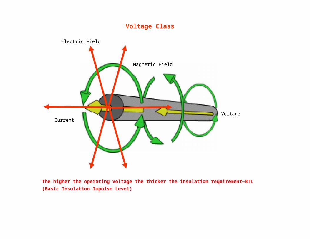
Electric Field
Magnetic Field
CurrentVoltage
The higher the operating voltage the thicker the insulation requirement—BIL (Basic Insulation Impulse Level)

Voltage Class
480 V
600 V
120 V
Conductors of Different systems can occupy the same raceway, cables, or enclosures if the insulation voltage rating is not less than the maximum circuit voltage

Voltage Drop
Voltage Drop depends on the load current, conductor size, distance of load to supply and temperature

Conduit Fill
4 -6 80
7-9 70
10-20 50
21-30 45
31 -40 40
41 and above 35
Ampacity Derating Factor
600 mm

Color Coding
White or Gray – Neutral
Red and/or Black – Hot
Green - Grounding

Color Coding

Conductor Size and Support
Voltage ApplicationSize for span less than Size for span less than
15 m 15 m
600 Volts or less 5.5 sq mm Copper 8.0 sq mm Copper
600 Volts or less 8.0 sq mm Aluminum 14.0 sq mm Aluminum
600 Volts or more 14.0 sq mm Copper8.0 sq mm Cable
Copper
600 Volts or more 22.0 sq mm Aluminum14.0 sq mm Cable
Aluminum
Festoon Lighting – Overhead conductor shall not be smaller than 3.5 sq mm copper unless the conductor is supported by a messenger wire. In span exceeding 12 m there shall be messenger wire.

Service Entrance

Service Entrance

Service Entrance
600 Volts, Nominal, or Less. Conductors of 600 volts, nominal, or less, shall comply with the spacing provided in PEC
Over 600 Volts, Nominal. Conductors of over 600 volts, nominal, shall comply with the spacing provided in PEC
Separation from Other Circuits. Open conductors shall be separated from open conductors of other circuits or systems by not less than 100 mm.

Service Entrance
Conductors on Poles. Conductors on poles shall have a separation of not less than 300 mm where not placed on racks or brackets. Conductors supported on poles shall provide a horizontal climbing space not less than the following:
1. Power conductors below communications conductors — 760 mm
2. Power conductors alone or above communications conductors: a. 300 volts or less — 600 mm.b. Over 300 volts — 760 mm.
3. Communications conductors below power conductors — same as power conductors
4. Communications conductors alone — no requirement

Service Drop
Overhead spans of open conductors and open multi-conductor cables of not over 600 volts, nominal, shall conform to the following:
3000 mm — above finished grade, sidewalks, or from any platform or projection from which they might be reached where the voltage does not exceed 150 volts to ground and accessible to pedestrians only
3600 mm — over residential property and driveways, and those commercial areas not subject to truck traffic where the voltage does not exceed 300 volts to ground
4500 mm — for those areas listed in the 3700 m classification where the voltage exceeds 300 volts to ground
5500 mm — over public streets, alleys, roads, parking areas subject to truck traffic, driveways on other than residential property, and other land traversed by vehicles, such as cultivated, grazing, forest, and orchard

Service Drop
Above Roofs. Conductors shall have a vertical clearance of not less than 2500 mm from the roof surface. The vertical clearance shall be maintained for a distance not less than 900 mm in all directions from the edge of the roof.
Horizontal Clearances. Clearances shall not be less than 1000 mm
Clearance from Windows. Final spans to the building they supply, or from which they are fed, shall be permitted to be attached to the building, but they shall be kept not less than 900 mm from windows that are designed to be opened, and from doors, porches, balconies, ladders, stairs, fire escapes, or similar locations.
Zone for Fire Ladders. Where buildings exceed three stories or 15 meters in height, overhead lines shall be arranged, where practicable, so that a clear space (or zone) at least 1800 mm wide will be left either adjacent to the buildings or beginning not over 2500 mm from them to facilitate raising of ladders when necessary for fire fighting.

Service Equipment
Service Equipment – Enclosed or Guarded. Energized parts of service equipment shall be enclosed as specified below,
Enclosure - Energized parts shall be enclosed so that they will not be exposed to accidental contact or guarded Guarded - Energized parts that are not enclosed shall be installed on a switchboard, panelboard, or control board and guarded. Such an enclosure shall be provided with means for locking or sealing doors giving access to energized parts
Grounding and Bonding - Service equipment, raceways, cable armor, cable sheaths, etc., and any service conductor that is to be grounded shall be grounded

Lighting Equipment on Poles or Other Structure
Common Neutral -The ampacity of the neutral conductor shall not be less than the maximum net computed load current between the neutral and all ungrounded conductors connected to any one phase of the circuit.
277 Volts to Ground - Circuits exceeding 250 volts nominal, between conductors and not exceeding 277 volts nominal, to ground shall be permitted to supply lighting fixtures for illumination of outdoor areas of industrial establishments, office building, institutional, stores, and other commercial or public buildings where the fixtures are not less than 900 mm from windows, platforms, fire escapes, and the like.
600 Volts Between Conductors - Circuits exceeding 277 volts nominal, to ground and not exceeding 600 volts nominal, between conductors shall be permitted to supply the auxiliary equipment of electric-discharge lamps

Lighting Equipment on Poles or Other Structure
Wiring on Buildings - The installation of outside wiring on surfaces of buildings shall be permitted for circuits of not over 600 volts nominal as open wiring on insulators, as multiconductor cable, as Type MC cable, as Type MI cable, as messenger supported wiring, in rigid metal conduit, in intermediate metal conduit, in rigid nonmetallic conduit, in cable trays, as cablebus, in wireways, in auxiliary gutters, in electrical metallic tubing, in flexible metal conduit, in liquid-tight flexible metal conduit, liquid-tight flexible nonmetallic conduit, and in busways.
Open-Conductor Supports - In spans exceeding 12 metres, the conductors shall be supported by a messenger wire; and the messenger wire shall be supported by strain insulators. Conductors or messenger wires shall not be attached to any fire escape, downspout, or plumbing equipment

Service Entrance

Service Entrance

Service Entrance

Rating of Disconnect
One Circuit Installation – For a limited load the rating shall not be less than 15 A Dwelling Unit – With a single branch circuit the disconnect shall not be smaller
than 20 A Two Circuit Installation – For not more than two 2 wire branch circuit the disconnect shall
have a rating of not less than 30 A One Family Dwelling – The feeder disconnecting means shall have a rating of not less than
60 A All Others shall not have a rating of not less than 30 A

Methods of Grounding
Grounding can be divided into two areas: system grounding and equipment grounding.
These two areas are kept separate from each other except at the point where they receive their source of power, such as at the service equipment or at a separately derived system.
Grounding is the intentional connection of a current-carrying conductor to ground or something that serves in place of ground.
In most instances, this connection is made at the supply source, such as a transformer, and at the main service disconnecting means of the premises using the energy.

Methods of Grounding
There are three basic reasons for grounding:
To limit the voltages caused by lightning or by accidental contact of the supply conductors with conductors of higher voltage
To stabilize the voltage under normal operating conditions (which maintains the voltage at one level relative to ground, so that any equipment connected to the system will be subject only to that potential difference)
To facilitate the operation of overcurrent devices, such as fuses, circuit breakers, or relays, under ground-fault conditions

Grounding System
On AC premises wiring systems, the conductor to be grounded shall be as specified in the following:
1. Single-phase, 2-wire — one conductor2 . Single-phase, 3-wire — the neutral conductor3. Multiphase systems having one wire common to all phases — the common conductor4. Multiphase systems where one phase is grounded — one phase conductor5. Multiphase systems in which one phase is used as in 2— the neutral conductor

Grounding System
Used green color as grounding conductor

Grounding System
Used green color as grounding conductor

Grounding System

Grounding System
The grounding rod resistance should be 25 ohms or less
Roel B. Calano

Grounding System
On AC premises wiring systems, the conductor to be grounded shall be as specified in the following:
1. Single-phase, 2-wire — one conductor2 . Single-phase, 3-wire — the neutral conductor3. Multiphase systems having one wire common to all phases — the common conductor4. Multiphase systems where one phase is grounded — one phase conductor5. Multiphase systems in which one phase is used as in 2 — the neutral conductor

Neutral Conductor

Raceway Methods and Materials
Cable Trays - Are open raceway like assemblies made of steel aluminum or a suitable non-metallic material they are used in buildings to route cables and support them out of the way of normal building activities
Trough Type Trays - Protect cables from damages and give good support and ample ventilation through straight sections
Ladder Trays - Provide maximum ventilations to power cables and other heat-producing cables
** Cables suitable for use in cable trays are marked CT (Cable Tray) on the outside of the jacket

Electrical System Protection – BasicComponents
Voltage transformers and current transformers: To monitor and give accurate feedback about the healthiness of a system.
Relays: To convert the signals from the monitoring devices, and give instructions to open a circuit under faulty conditions or to give alarms when the equipment being protected, is approaching towards possible destruction.
Fuses: Self-destructing to save the downstream equipment being protected.

Electrical System Protection – Basic
Components
Circuit breakers: These are used to make circuits carrying enormous currents, and also to break the circuit carrying the fault currents for a few cycles based on feedback from the relays.
DC batteries: These give uninterrupted power source to the relays and breakers that is independent of the main power source being protected

Motor Installation

Motor Installation

Multiple Motor Installation
Feeder Rating = 125 % HFLA in a group + 100 % sum of Other FLA in a group

Multiple Motor Installations
Inverse Time Setting = 250 % HFLA in a group + 100 %
sum of Other FLA
in a group

Motor Installation

Wiring Methods

Drives, Excitation and Regulation
Automatic Control
ExcitationSystem
Power
Drives
DC Generator AC Motor
Exciter

Generator Operation
The Generator Spins above synchronous speed
Mechanical Energy is Transformed into Kinetic Energy and is Converted into Electrical Energy Delivers Active Power to the Electrical System
The Electrical System must provide Reactive Power for the creation of Magnetic Field High Engine speeds produced greater electrical output
Load
Generator Prime Mover
Exciter

Generator Operation
The Generator size is affected by the rating, enclosure and the application Typical prime mover is a diesel engine Power Rating is
expressed in Watts Generator exciter provides residual magnetism
As the load of Generator increases the frequency decreases
LoadGenerator Prime Mover
Exciter

Power Measurement
Wattmeter Ammeter Voltmeter
Load
Generator
Exciter

Surge Arrester Selection
Circuits of Less Than 1000 Volts. The rating of the surge arrester shall be equal to or greater than the maximum continuous phase-to-ground power frequency voltage available at the point of application.
Surge arresters installed on circuits of less than 1000 volts shall be listed for the purpose.
Circuits of 1 kV and Over — Silicon Carbide Types. The rating of a silicon carbide-type surge arrester shall be not less than 125 percent of the maximum continuous phase-to-ground voltage available at the point of application.

Connecting Surge Arrester
Installed at Services of Less Than 1000 Volts. Line and ground connecting conductors shall notbe smaller than 14 AWG copper or 12 AWG aluminum. The arrester grounding
conductor shall be connected to one of the following:
Grounded service conductor Grounding electrode conductor Grounding electrode for the service
Equipment grounding terminal in the service equipment

Surge Arrester Selection
Line and ground connecting conductors shall not be smaller than 14 AWG copper or 12 AWG aluminum.
A surge arrester shall be permitted to be connected between any two conductors — ungrounded conductor(s), grounded conductor, grounding conductor
The grounded conductor and the grounding conductor shall be interconnected only by the normal operation of the surge arrester during a surge.

Surge Arrester Selection
Circuits of 1 kV and Over — Surge-Arrester Conductors.
The conductor between the surge arrester and the line and the surge arrester and the grounding connection shall not be smaller than 6 AWG copper or aluminum.

Lightning Arrester
Lightning arresters are protective devices for limiting surge voltages due to lightning strikes or equipment faults or other events, to prevent damage to equipment and disruption of service.

Cable Wiring Methods and Materials
Armored Cable ( AC, ACT, and ACL ) - fabricated assembly of insulated conductors enclosed in a flexible metal sheath used both in exposed and concealed work for branch circuit and feeders in both exposed and concealed work and in cable tray where identified for such use.
Metal Clad Cable ( MC ) - factory assembled cable of one or more conductors, each individually insulated and enclosed in a metallic sheath interlocking tape, or a smooth or corrugated tube, used specifically for services, feeders, branch circuit, either exposed or concealed, and for indoor or outdoor work.
Metal Insulated Cable, Metal Sheathed Cable ( MI ) - factory assembled cable of one or more conductors insulated with highly compressed refractory mineral insulation and enclosed in a liquid tight and gas tight continuous copper sheath, used in a dry , wet, or continuously moist location as in service, feeders, or branch circuits, indoors or outdoors, exposed or concealed.

Cable Wiring Methods and Materials
Non-metallic Sheated Cable (NM and NMC) - factory assembled two or more insulated conductors having a moisture resistant, flame retardant and non-metallic outer sheath. used specifically for one or two family dwellings, multifamily dwellings and other structure
Shielded Non-metallic Sheated Cable (SNM) - A factory assembled two or more insulated conductors in an extruded core of moisture resistant and flame resistant non-metallic, covered with an overlapping spiral metal tape and wire shield and jacketed with an extruded moisture, flame, oil, corrosion, fungus and sunlight resistant non-metallic material. Used where operating temperature do not exceed the rating worked on the cable
Service Entrance Cable (SE & USE) - A single or multi-conductor assembly provided with or without an overall covering, primarily and for services. Used for installation in cable trays, raceways or where supported by a messenger wire.

Cable Wiring Methods and Materials
Underground Feeder and Branch Circuit Cable (UF) - A moisture resistant cable. Used for underground, including direct burial in the earth, as feeder or branch circuit cable
Power & Control Tray cable (TC) – A factory assembled two or more insulated conductors with or without associated bare or covered grounded conductor under nonmetallic sheath.
Flat Cable Assemblies (FC)- An assembly of parallel conductors formed integrally with an insulating material web specially designed for field installation in metal surface raceway. Used for branch circuit not exceeding 30 amperes and in locations where they will not be exposed to severe physical damage.

Cable Wiring Methods and Materials
Flat Conductor Cable (FCC) - Consists of three or more flat copper conductor placed edge to edge & separated and enclose within an insulating assembly. Used for general purpose and appliance branch circuits and for individual branch circuits specifically in hard, smooth, continuous floor surfaces specially for under carpet (up to 914 mm2) wiring to floor outlets (floor mounted type FCC).
Medium Voltage Cables (MV) - single or multi-conductor solid dielectric insulated cable rated at 2,001 or higher. Used for power system up to 35,000 volts nominal, in wet or dry locations, in raceway, cable trays.
Integrated Gas Spacer Cable (IGS) - A factory assembled cable of one or more conductors, each individually insulated and enclosed in a loose fit nonmetallic flexible conduit rated 0 to 600 V.

Cable Wiring Methods and Materials
Integrated Gas Spacer Cable (IGS) - A cable and conduit system for underground use, including direct burial in the earth, as service-entrance conductors or as feeder or branch circuit conductors advantages include low material and installation cost, eliminate field pulling or cables into conduit and eliminates the cost of assembly of conduit in the field. Uses SF6 (sulfuric hexafluoride gas) insulation.

Raceway Methods and Materials
Raceways - The raceways wiring accessories or channels designed for holding wires cables, or busbars which are either made of metal or any insulating material. They provided mechanical protection to conductors while keeping them accessible for wiring changes: conduits connectors, conduit, coupling, clamps, hangers etc. cable trays, bus metal raceway, non-metal raceways.
Conduits - Either pipes or tubing, which are either flexible or rigid for electric wires. The most common electrical raceways.
Fittings - Accessories such as locknuts, bushing couplers, adapters nipples and connectors or other part wiring system that is intended primarily to perform a mechanical rather than function.
Connectors - A metal sleeve, usually made of copper, that is slipped over and secure to the butted ends conductors in making a joint. Also called a splicing sleeve.

Raceway Methods and Materials
Intermediate Metal Conduit (IMC) - A metal raceway of circular cross-section with integral or associated couplings, connectors and fittings approved for the installation of electrical conductors has wall thickness less than rigid metal conduit but greater than EMT used in all atmospheric conditions and occupancies, or areas subject to severe corrosive influences when protected by corrosion protection
Rigid Metal Conduit - Similar to that of IMC and when installed in concrete or in contact with coil, it does not generally require supplementary corrosion protection unless subject to severe corrosive influences
Rigid Non-metallic Conduit - Resistant to moisture and chemical atmospheres underground materials, fiber, soapstone, rigid polvinyl chloride (PVC), fiberglass, epoxy, and high density polyethylene, above ground (PVC)
Raceway Methods and Materials
Electrical Metallic Tubing - General purpose raceway of the same nature as rigid metal conduit and IMC used for both exposed and concealed work where it will not be subjected to severe physical damage or (unless suitably protected) to corrosive agents
Flexible Metallic Tubing - Circular in cross-section, flexible, metallic and liquidtight without a nonmetallic jacket used in dry locations, in accessible locations when protected from physical damage or concealed such as above suspended ceilings and branch circuits
Surface Metal Raceway - Used for exposed wiring where the possibility of severe physical damage is not a problem restricted to dry locations and voltages under 300 volts its principal use is for rewiring or extending existing electrical system.

Raceway Methods and Materials
Under Floor Raceways - Called under floor ducts, consist of separate duct system buried in the concrete floor or flush with surface of the floor it come complete with junction boxes and fittings to provide access along the length of the duct for receptacles and telephone outlets may consists of single, double, or triple ducts run parallel to provide telephone signal and power raceways.
Wire ways - Ducts with square or rectangular cross-section made of sheet metal and the standard length of each ducts is 10 feet where the wiring is readily accessible through cover plates, which make up one of the walls of the ducts, is 10 feet cover plates may be hinged or unhinged, screwed in place, or merely snapped into place cannot be buried, concealed in walls or exposed to corrosives atmosphere for in general they are mounted exposed outdoors and may carry systems rated at 600 volts.
Raceway Methods and Materials
Cellular Floor Raceways - Maybe metal or concrete, where cells of the cellular floor system is assigned with particular usage for power or signal wiring, and a header ducts tap into the cells and a carry the wiring to the necessary panel board or boxes.
Busways - An approved completely assembled metal troughing and fitting when contain bare conductors intended for use as feeders, the conductors being suitably supported of insulators. Factory made systems of copper of aluminum bars, rods, or tubes designed to carry heavy currents from 50 to 6,000 amp conductors can be solid bars, square or rectangular hollow tube hollow ovals or solid 1 – beams. Can be mounted horizontally or vertically and can be also used as service entrance feeders.
Raceway Methods and Materials
Continuous plug in Busways - used to serve equipment that may be relocated periodically, such as in wood working shops. Have regularly spaced openings that permitted plugging of switches or circuit breakers and conduit or flexible cable is then run from devices to the equipment being served.
Trolley Busways - Permits travelling equipment to be connected to a power source a rolling power takeoff in contact with the busways conductors as the equipment moves, the trolley contact on the conductor.
Cablebus - An approved assembly of insulated conductors with fittings and conductor terminations in a completely enclosed, ventilated protective metal housing
Electrical System Design
Receptacle spacing = 1800 mm from the door

Riser Diagram/Distribution System


