PEER-REVIEWED ARTICLE bioresources.com He et al. (2016). “Timber-concrete structures,” BioResources 11(4), 9205-9218. 9205 Shear Behavior Study on Timber-Concrete Composite Structures with Bolts Guojing He, a Lan Xie, a, * Xiaodong (Alice) Wang, b Jin Yi, a Lening Peng, a Zi’ang Chen, a Per Johan Gustafsson, c and Roberto Crocetti c The key point of design for timber-concrete composite structure is to ensure the reliability of shear connectors. This study examined the mechanical properties of bolt-type connectors in timber-concrete composite structures theoretically and experimentally. The theoretical study was based on the Johansen yield theory (European Yield Model). Push-out specimens with different bolt dimensions were tested to determine the shear capacity and slip modulus. According to the experimental results, bolts yielded without timber or concrete cracks when the stiffness of bolts was not very great. The shear capacity and slip modulus of the bolt connectors were directly proportional to the diameter of the bolt. The strength of concrete was found to significantly affect the shear capacity of bolt connectors. Comparison between the theoretical and the experimental shear strength results showed reasonable agreement. Keywords: Timber-concrete composite structure; Bolt connectors; Mechanical model; Shear capacity equation; Push-out tests; Slip modulus Contact information: a: Department of Civil Engineering and Mechanics, Central South University of Forestry and Technology, 498 Shaoshan Road, Changsha, Hunan, 410004 China; b: Wood Technology and Engineering, Luleå University of Technology, Forskargatan 1, SE-931 87 Skellefteå, Sweden; c: Division of Structural Mechanics, Lund University, Box 188, 221 00 Lund, Sweden; * Corresponding author: [email protected]; [email protected]INTRODUCTION Timber-concrete composite structures have been utilized in Europe over the past 50 years, especially in new buildings (Natterer et al. 1996) and in the upgrading of existing timber floors. A timber-concrete composite (TCC) structure contains a concrete slab and a timber joist. The upper concrete flange and timber joist may be connected with various kinds of shear connectors. In this case, the concrete bears compression force, while the timber fiber is in tension. The TCC structure brings the superiority of those two materials into full play. TCC structures are strong and stiff, and thus perform well in dead load, earthquake, and fire (Skinner et al. 2014). In contrast to concrete structures, TCC structures are highly energy efficient and can significantly reduce CO2 emissions through a carbon sequestration mechanism, as timber is a carbon store (Rodrigues et al. 2013). These features are the advantages of timber-concrete composite structure (Lukaszewska 2009). In China, the importance of environmental protection is increasingly realized and the use of TCC will probably become extensive also in China. Notably, it is important to use connectors that are strong and stiff enough to resist the shear force in the composite structure (Yeoh et al. 2011). Various kinds of connectors have been developed, including screw or stud connectors, dowels, and notches cut in the timber and filled with concrete. Mascia and Soriano (2004) studied the properties of TCC
Transcript
PEER-REVIEWED ARTICLE bioresources.com
He et al. (2016). “Timber-concrete structures,” BioResources 11(4), 9205-9218. 9205
Shear Behavior Study on Timber-Concrete Composite Structures with Bolts
Guojing He,a Lan Xie,a,* Xiaodong (Alice) Wang,b Jin Yi,a Lening Peng,a Zi’ang Chen,a
Per Johan Gustafsson,c and Roberto Crocetti c
The key point of design for timber-concrete composite structure is to ensure the reliability of shear connectors. This study examined the mechanical properties of bolt-type connectors in timber-concrete composite structures theoretically and experimentally. The theoretical study was based on the Johansen yield theory (European Yield Model). Push-out specimens with different bolt dimensions were tested to determine the shear capacity and slip modulus. According to the experimental results, bolts yielded without timber or concrete cracks when the stiffness of bolts was not very great. The shear capacity and slip modulus of the bolt connectors were directly proportional to the diameter of the bolt. The strength of concrete was found to significantly affect the shear capacity of bolt connectors. Comparison between the theoretical and the experimental shear strength results showed reasonable agreement.
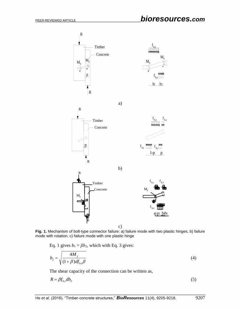
A TCC structure will fail if any component fails. But it mainly fails because of
failure of a connection. In accordance with the Johansen yield theory (Johansen 1962),
the possible failure modes are presented in Fig. 1. The equilibrium expressions (Eqs. 1 to
12), corresponding to situations in which there was a balance of forces or moment, were
obtained according to the failure modes.
In Fig. 1 a), at a plastic hinge, the shear force is zero (Li et al. 2014), and the
bending moment has its maximum value, My. The diameter of the bolt in Fig. 1 a) was
denoted as d, and the stresses acting on the bolt in timber and concrete were assumed as
reaching the embedment strength, fh,t and fh,c, respectively. Thus, the equilibrium is
written as,
2,2,1, dbfdbfdbf thchth (1)
where thf , =embedment strength in timber; chf , = embedment strength in concrete;
d =diameter of bolt; 1b =distance between plastic hinge in timber and timber edge;
2b =
distance between concrete edge and plastic hinge in concrete; =ratio of embedment
strength in concrete and in timber (see Eq. 2).
th
ch
f
f
,
, (2)
The moment equilibrium at the yielding point of bolts in timber is determined by,
)2
(2
2 212,
2
1,
bbdbf
bdfM chthy (3)
where yM =yield moment of bolt, other variables are the same as Eq. (1) and Eq. (2).
PEER-REVIEWED ARTICLE bioresources.com
He et al. (2016). “Timber-concrete structures,” BioResources 11(4), 9205-9218. 9207
p
R
R
fh,t
MyMy
fh,c
b1 b2
Timber
ConcreteMy
My
a)
p
R
R
fh,t
fh,c
l-p p
Timber
Concrete
fh,c
fh,t
b)
p
R
R
fh,t
My
fh,c
a1 b1
Timber
Concrete My
b1a2
fh,c
c)
Fig. 1. Mechanism of bolt-type connector failure: a) failure mode with two plastic hinges, b) failure mode with rotation, c) failure mode with one plastic hinge
Eq. 1 gives b1 = βb2, which with Eq. 3 gives:
th
y
df
Mb
,
2)1(
4
(4)
The shear capacity of the connection can be written as,
2, dbfR th (5)
PEER-REVIEWED ARTICLE bioresources.com
He et al. (2016). “Timber-concrete structures,” BioResources 11(4), 9205-9218. 9208
which gives:
)1(
4 ,
dfMR
thy (6-a)
In Fig 1 b), the shear capacity of the connection can be written as,
pl
p
pl
p
pl
p
pl
ppldfR th 112
1
)(2
3
2
2,
(6-b)
where l = the total length of bolt, and p = penetration depth of bolt in concrete. In Fig 1 c),
the shear capacity of the connection can be written as,
)1(2
)2(4
2 2
,
2
,
dpf
MdpfR
th
yth (6-c)
where ch
th
f
f
,
, , 1a ,
2a ,1b are presented in Fig. 1 c).
In the mechanical model stated previously, the withdrawal force and frictional
force were not taken into account because they were very low. Therefore, Eq. 6 is a
conservative estimate value for the shear capacity of bolt-type connectors in TCC
structures.
According to standard EN 1995-1-1 (2014) for bolts and laminated veneer lumber
(LVL), the embedment strength was conservatively estimated by Eq. 7, and the
characteristic value for the yield moment was estimated by Eq. 8 according to Blass et al.
( 2001).
kth df )01.01(082.0, (7)
where k is the characteristic timber density, in kg/m3,
6.23.0 dfM uy (8)
where fu is the characteristic tensile strength of the bolt in N/mm2.
Because the bolts fail in the concrete when the composite structure reaches its
ultimate capacity, information about the embedment strength of the concrete is needed.
The embedment strength is assumed to be,
dh
Pf u
ch , (9)
where d is the diameter of the bolt, h is the total length in concrete block including the
head length of the bolt, and the uP is the shear force resistance of bolt in a concrete
encasement, which is assumed according to Eq. 6.19 in Eurocode 4 (EN 1994-1-1 2004).
The shear forces resistance is given by,
cmck EfdP 2
u 29.0 for 4/ dh (10)
PEER-REVIEWED ARTICLE bioresources.com
He et al. (2016). “Timber-concrete structures,” BioResources 11(4), 9205-9218. 9209
where d is the diameter of the bolt, ckf is the characteristic cylinder compressive
strength of the concrete, and cmE is the mean secant modulus of elasticity of concrete.
Then, Eqs. 7 through 10 were substituted into Eq. (6), such that the capacity of
bolt-type connector is written as,
))1(2)2(2.1
2
)1121
)(
)24.74)01.0-1(082.0
)01.01(305.7
2
,
26.2,
2
3
2
2,
6.3
cdpf
dfdpf
bpl
p
pl
p
pl
p
pl
ppldf
aEfddh
Efddf
R
th
uth
th
cmckk
cmckku
(11)
where R is the shear capacity in N, the other variables are the same as aforementioned, in
Eq. 11 b) and c), is a parameter which can be written as,
)01.01(082.0
29.0 2
ddh
Efd
k
cmck
(12)
Materials Timber
Xing’an larch is a hardwood that is appropriate for engineering applications. The
xing’an larch wood used in these experiments was grown in the forest of the Great
Khingan Mountains of China, and was bought from a furniture factory in Central South
University of Forestry and Technology, Changsha, Hunan, China. All glued timber
blocks used in the tests were made of the larch wood and glued with polyurethane.
According to the standard method for testing mechanical properties of timber
structures (GB/T 50708 2012), three full scale specimens with dimensions of 200 mm ×
120 mm × 400 mm were tested (Fig. 2), and the compressive strength was by tests
found to be 44.9 MPa.
Fig. 2. Compressive strength full scale tests of timber
Note: the length of bolt does not include the head, which is 10 mm long.
PEER-REVIEWED ARTICLE bioresources.com
He et al. (2016). “Timber-concrete structures,” BioResources 11(4), 9205-9218. 9211
50
150
200
50
450
60 p x p 6060 200 60
320
90
300
120
90
timber
concrete
Vertical View Side View
Plan View
90 120 90300
150 150
50
150
200
50
450
60 p x p 6060 200 60
320
150
150
Fig. 4. Drawings of timber-concrete composite push-out specimens (in mm)
Test Methods The standard BS EN 26891 (BS EN 26891 1991) was followed for the statically
loaded tests of TCC specimens. The loading procedure was followed according to Fig. 5.
F /Fest
1.0
0.9
0.8
0.7
0.6
0.5
0.4
0.3
0.2
0.1
0 2 4 6 8 Time (min)
01
02
03
04 14
13
12
11 21
22
23
24
25
26
27
2829
Fig. 5. Load procedure for tests according to EN 26891
PEER-REVIEWED ARTICLE bioresources.com
He et al. (2016). “Timber-concrete structures,” BioResources 11(4), 9205-9218. 9212
The test was conducted with a preliminary test and main test. In the preliminary
process, the load, F, was applied up to 0.4 Fest and maintained for 30 s, Fest being the
estimated failure load. Subsequently, the load was lowered to 0.1 Fest and maintained for
30 s. In the main test process, the test was conducted under load control until 0.4 Fest,
followed by displacement control until 15 mm or structure failure.
A universal testing machine (WEW-100, Shenzhen SANS Materials Testing Co.,
Ltd., Shenzhen, China) was used to apply load to the top surface of the timber in TCC
specimens. Four displacement gauges were used to measure the interlamination slip
between the concrete and the timber (Fig. 6).
50
150
200
50
450
60 p x p 6060 200 60
320
timber
L
D1(3)
D2(4)
Fig. 6. Testing apparatus
RESULTS AND DISCUSSION
Load-slip curves for all series of specimens are presented here, together with the
ultimate load (Fmax), initial slip (δ), and slip modulus (KS). The initial slip is the slip
corresponding to point 04 in Fig. 5. The slip modulus was calculated with
mod,/4.0 iests vFk , where mod,iv represents modified initial slip, which was calculated with,
)(3
40104mod, vvvi (13)
The quantities 04v and 01v are the slip corresponding to point 04 and 01,
respectively. These parameters are usually necessary for the design of the TCC structures
(Dias 2005). The initial slip and slip modulus can be calculated according to BS EN
26891 (1991). The mean values, characteristic values and coefficient of variation of the
test are presented in Table 2 and Fig. 7. To validate the experimental strength to
aforementioned equation, the characteristic values were calculated according to SS EN
14358 (2016).
PEER-REVIEWED ARTICLE bioresources.com
He et al. (2016). “Timber-concrete structures,” BioResources 11(4), 9205-9218. 9213
Table 2. Results for Specimens with Bolt-Type Fasteners
No.
Strength
Fmax (kN) Initial Slip
δi (mm) Slip Modulus
Ks (kN/mm)
Value Mean/
Characteristic Value Cov* Value Mean Cov* Value Mean Cov*
D8L120-1 30.74
27.41/20.50 0.10
1.17
1.67 0.21
11.48
7.55 0.37 D8L120-2 27.54 1.95 6.16
D8L120-3 23.94 1.88 5.02
D12L120-1 39.48
39.66/- 0.22
0.88
2.29 0.72
15.22
11.00 0.48 D12L120-2 50.45 1.4 14.29
D12L120-3 29.03 4.59 3.48
D16L120-1 58.70
61.29/49.51 0.05
0.77
1.27 0.48
42.55
31.18 0.57 D16L120-2 65.58 0.92 35.76
D16L120-3 59.59 2.12 15.23
D16L100-1 54.60
53.01/40.80 0.06
0.695
2.16 0.81
33.09
19.96 0.54 D16L100-2 48.59 4.63 6.88
D16L100-3 55.84 1.16 19.91
*Coefficient of variation
0
5
10
15
20
25
30
35
0 5 10 15
Slip(mm)
Fo
rce (
kN
)
D8L120-1 D8L120-2 D8L120-3
0
10
20
30
40
50
60
0 5 10 15
Slip(mm)
Fo
rce (
kN
)D12L120-1 D12L120-2 D12L120-3
a) b)
0
10
20
30
40
50
60
70
0 5 10 15
Slip(mm)
Fo
rce (
kN
)
D16L120-1 D16L120-2 D16L120-3
0
10
20
30
40
50
60
0 5 10 15
Slip(mm)
Fo
rce (
kN
)
D16L100-1 D16L100-2 D16L100-3
c) d)
Fig. 7. Load-slip curves for all test groups: a) D8L120, b) D12L120, c) D16L120, and d) D16L100
The mechanical behavior of the bolt-type fasteners showed an obvious non-linear
performance for all series. The rate of the interlamination slip between the timber and
concrete of all the series of specimens increased with the slip. There was only some
minor noise from the timber when the load applied was between 0 to 0.4 times the
ultimate estimated load. As the load increased, the slip increased and the noise became
louder until the test was completed. When applying load, the timber slowly separated
from the concrete. The tests in the D8L120 group and the D12L120 group were stopped
when the slip reached 15 mm (BS EN 26891 1991); there was not any obvious material
PEER-REVIEWED ARTICLE bioresources.com
He et al. (2016). “Timber-concrete structures,” BioResources 11(4), 9205-9218. 9214
damage of concrete and timber, except the internal fiber extrusion damage caused by the
interlamination slips. The other test finished with a crack in the concrete.
Failure of the three specimens in group D16L100 involved sudden propagation of
a transverse horizontal crack in the left or right concrete block. Such cracking was not
expected and was most probably due to rotation of the bolt (Fig. 1 c)) and tensile stress in
the vicinity of the bolt. For specimen D16L100-1, the cracking load and crack width was
54.59 kN and 2.1mm, respectively. For specimen D16L100-2, the cracking load and
crack width was 48.42 kN and 2.5mm, respectively, and for specimen D16L100-3, it was
55.84 kN and 3.5mm, respectively. When the concrete cracked, for specimen D16L100-2
also wood-concrete slip developed, and for specimen D16L100-3 also a diagonal crack
developed in the concrete. The bolts in those specimens were found to be rotated. For test
group D16L120, there was failure for specimens 1 and 2 due to sudden development of a
vertical splitting crack at load 58.70 kN and 48.5 kN, respectively. The vertical crack was
caused by tensile stress in the vicinity of the bolt when the bolt rotated. Specimen
D16L120-3 failed at load 59.90 kN due to the horizontal type of cracking, for this
specimen giving crack width 2.0 mm. The bolts in those specimens were also found to be
rotated.
a) b)
c) d) e) f)
Fig. 8. Failure modes for timber-concrete composite specimens with bolt: a) bolt bended and failed, b) Slip on timber, c) concrete separated from timber, d) vertical crack, e) transverse crack, and f) Diagonal crack
Influence of Bolt Dimensions Table 3 shows the mean values for strength, initial slip, and slip modulus obtained
for the 2+3+3 tests D12L120-1, 2, D16L120-1, 2, 3, and D16L100-1, 2, 3 relative to the
corresponding mean results of the tests D8L120-1, 2, 3. All these specimens were cast
with concrete of the same quality. It seems that the strength is about proportional to the
PEER-REVIEWED ARTICLE bioresources.com
He et al. (2016). “Timber-concrete structures,” BioResources 11(4), 9205-9218. 9215
bolt diameter and the slip modulus is about proportional to the square of the bolt diameter.
Decreased bolt length save a slight decrease in strength and a significant decrease in slip
modulus.
Table 3. Relative Influence of Bolt Dimensions on Strength, Slip, and Stiffness
D L P Strength Initial Slip Slip modulus
8 120 80 1.00 1.00 1.00
12 120 80 1.64 0.68 1.95
16 120 80 2.24 0.76 4.13
16 100 60 1.93 1.30 2.64
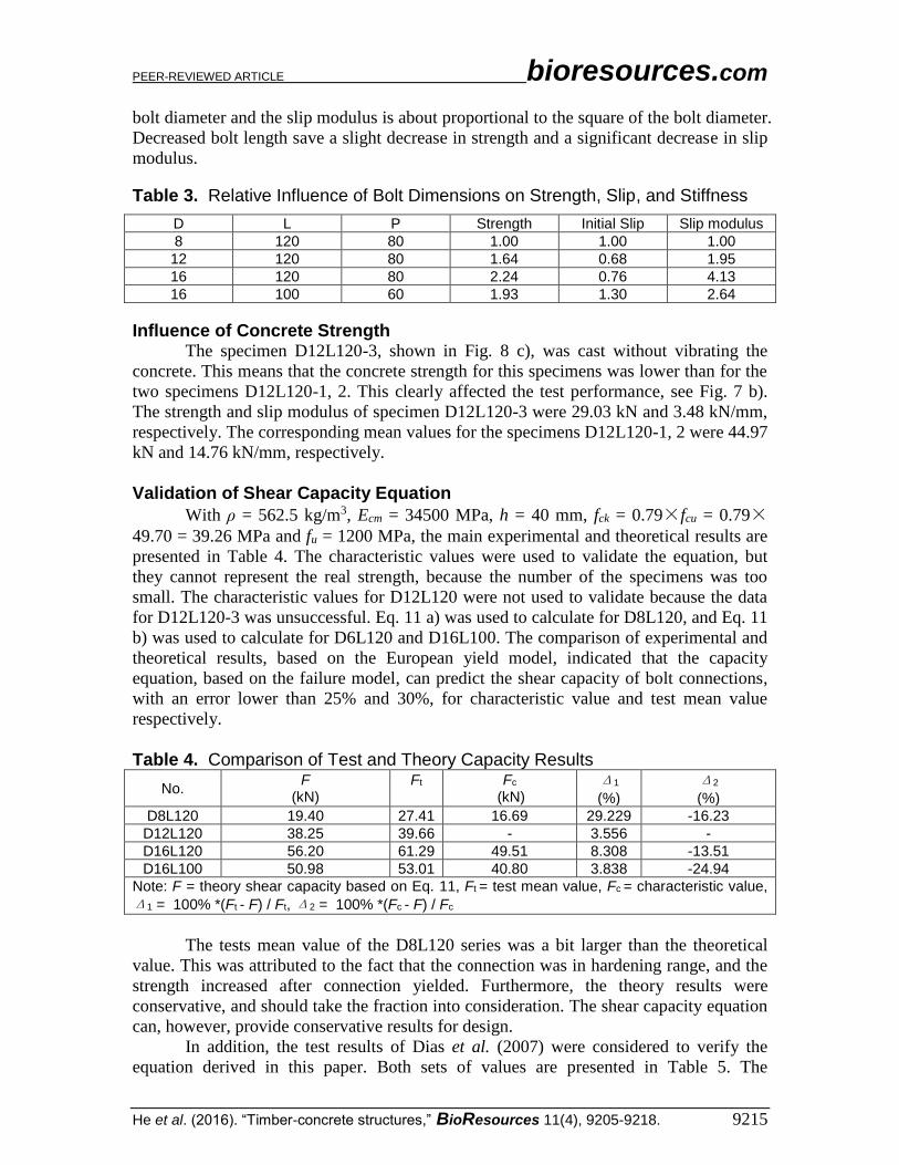
Influence of Concrete Strength The specimen D12L120-3, shown in Fig. 8 c), was cast without vibrating the
concrete. This means that the concrete strength for this specimens was lower than for the
two specimens D12L120-1, 2. This clearly affected the test performance, see Fig. 7 b).
The strength and slip modulus of specimen D12L120-3 were 29.03 kN and 3.48 kN/mm,
respectively. The corresponding mean values for the specimens D12L120-1, 2 were 44.97
kN and 14.76 kN/mm, respectively.
Validation of Shear Capacity Equation
With ρ = 562.5 kg/m3, Ecm = 34500 MPa, h = 40 mm, fck = 0.79×fcu = 0.79×49.70 = 39.26 MPa and fu = 1200 MPa, the main experimental and theoretical results are
presented in Table 4. The characteristic values were used to validate the equation, but
they cannot represent the real strength, because the number of the specimens was too
small. The characteristic values for D12L120 were not used to validate because the data
for D12L120-3 was unsuccessful. Eq. 11 a) was used to calculate for D8L120, and Eq. 11
b) was used to calculate for D6L120 and D16L100. The comparison of experimental and
theoretical results, based on the European yield model, indicated that the capacity
equation, based on the failure model, can predict the shear capacity of bolt connections,
with an error lower than 25% and 30%, for characteristic value and test mean value
respectively.
Table 4. Comparison of Test and Theory Capacity Results
No. F
(kN) Ft
Fc
(kN) Δ1
(%)
Δ2
(%)
D8L120 19.40 27.41 16.69 29.229 -16.23
D12L120 38.25 39.66 - 3.556 -
D16L120 56.20 61.29 49.51 8.308 -13.51
D16L100 50.98 53.01 40.80 3.838 -24.94
Note: F = theory shear capacity based on Eq. 11, Ft = test mean value, Fc = characteristic value,