Pega 244N With 04PC Layout Drawings ©Amada America, Inc.
Print Date 04/08/99 Revision 1.0 Page 1 of 13This document available on the World Wide Web at http://www.amada.com/support
Pega 244N With 04PC Layout Drawings
Amada America Inc.7025 Firestone Blvd.
Buena Park CA. 90621Phone: (714) 739 2111
Fax.: (714) 739 4099Email [email protected]
Pega 244N With 04PC Layout Drawings ©Amada America, Inc.
Print Date 04/08/99 Revision 1.0 Page 2 of 13This document available on the World Wide Web at http://www.amada.com/support
ContentsPlanning the Location of the Machine...................................................................................................................................3
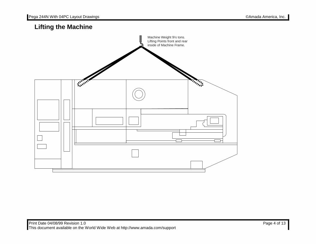
Lifting the Machine............................................................................................................................................................4Machine Dimensions - Plan View .....................................................................................................................................5Machine Dimensions - End View ......................................................................................................................................6Machine Dimensions - Elevation View..............................................................................................................................7Maintenance Areas...........................................................................................................................................................8
Foundation Requirements.....................................................................................................................................................9Foundation J-bolt Detail..................................................................................................................................................10Foundation Plan View.....................................................................................................................................................11Foundation Elevation View .............................................................................................................................................12
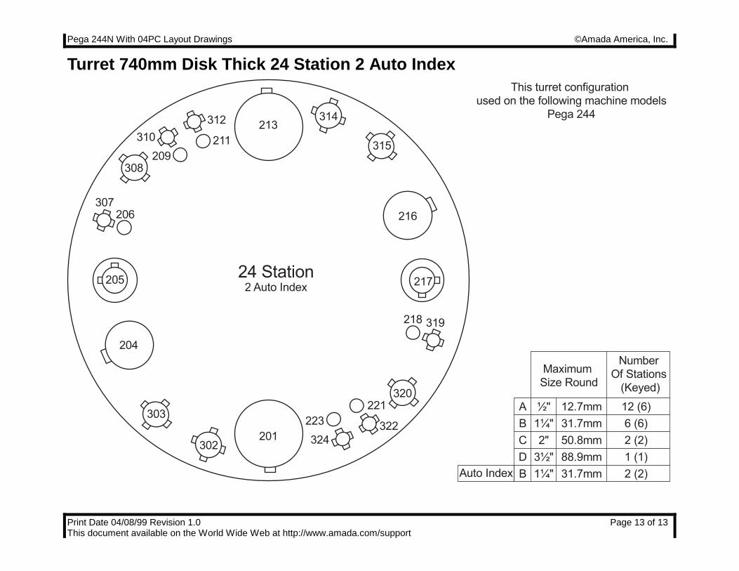
Turret 740mm Disk Thick 24 Station 2 Auto Index..............................................................................................................13
Pega 244N With 04PC Layout Drawings ©Amada America, Inc.
Print Date 04/08/99 Revision 1.0 Page 3 of 13This document available on the World Wide Web at http://www.amada.com/support
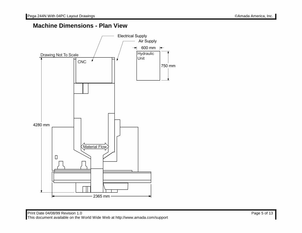
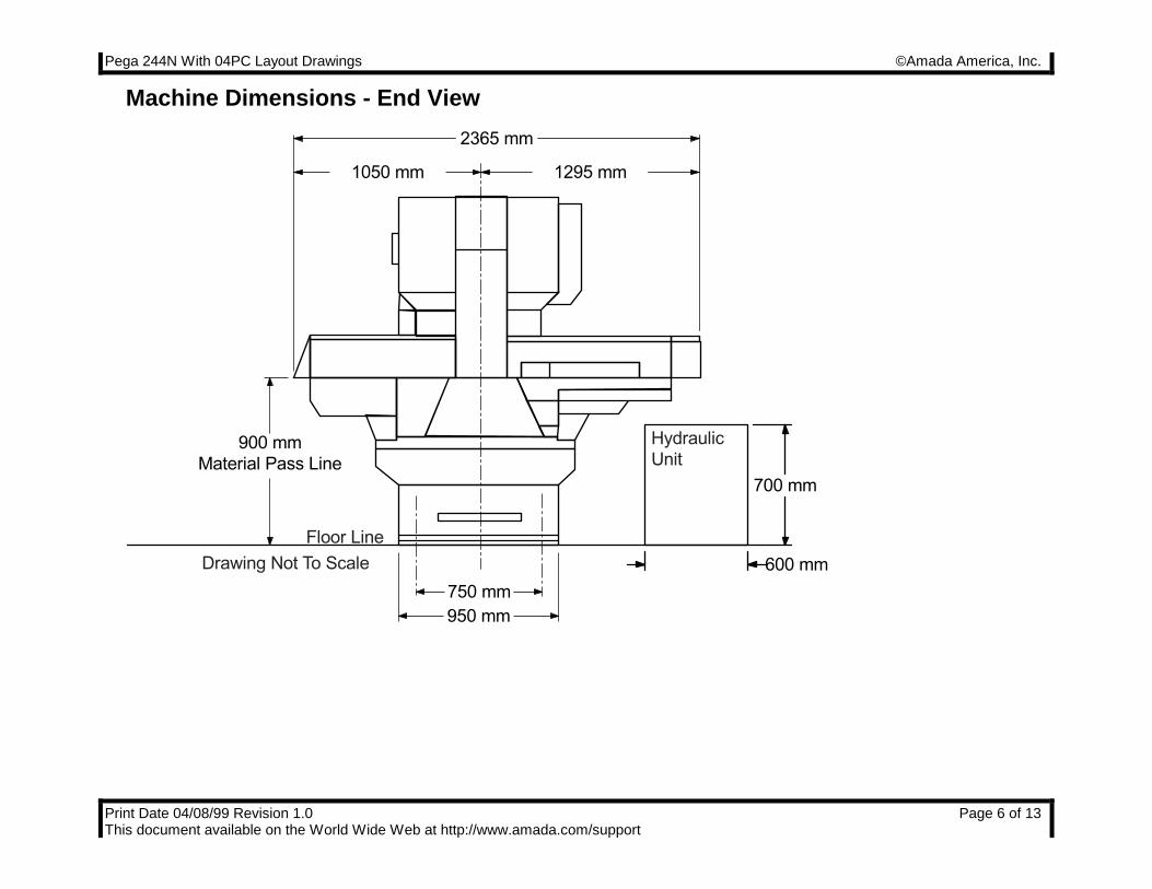
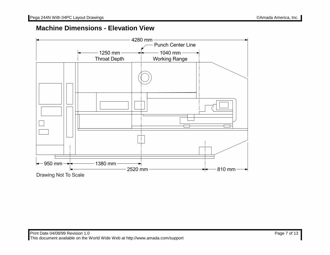
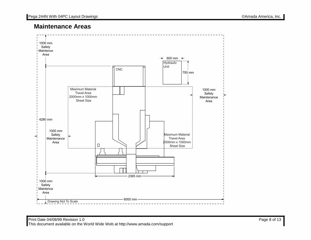
Planning the Location of the MachineThe following diagrams provide the details for positioning your new machine.
� No obstacles are allowed in the worksheet travel area and the ceiling must be at least 40" above the top of the Pega244N.
� All of the maintenance areas recommended should be used, but you must at least ensure that the doors of the FanucO4PC NC unit can be opened.
� The Pega 244N and Fanuc O4PC control must be protected from direct sunlight or other heat sources. It has beenshown that radiant type heaters can cause serious tool alignment problems.
Pega 244N With 04PC Layout Drawings ©Amada America, Inc.
Print Date 04/08/99 Revision 1.0 Page 4 of 13This document available on the World Wide Web at http://www.amada.com/support
Lifting the MachineMachine Weight 9½ tons.Lifting Points front and rear inside of Machine Frame.
Pega 244N With 04PC Layout Drawings ©Amada America, Inc.
Print Date 04/08/99 Revision 1.0 Page 5 of 13This document available on the World Wide Web at http://www.amada.com/support
Machine Dimensions - Plan View
Electrical Supply
Air Supply
4280 mm
2365 mm
750 mm
600 mm
Hydraulic
UnitDrawing Not To Scale
CNC
Material Flow
Pega 244N With 04PC Layout Drawings ©Amada America, Inc.
Print Date 04/08/99 Revision 1.0 Page 6 of 13This document available on the World Wide Web at http://www.amada.com/support
Machine Dimensions - End View
Drawing Not To Scale
900 mm
Material Pass Line
2365 mm
600 mm
700 mm
950 mm
750 mm
1050 mm 1295 mm
Floor Line
Hydraulic
Unit
Pega 244N With 04PC Layout Drawings ©Amada America, Inc.
Print Date 04/08/99 Revision 1.0 Page 7 of 13This document available on the World Wide Web at http://www.amada.com/support
Machine Dimensions - Elevation View
Punch Center Line4280 mm
1040 mm
Working Range
1250 mm
Throat Depth
950 mm810 mm2520 mm
1380 mm
Drawing Not To Scale
Pega 244N With 04PC Layout Drawings ©Amada America, Inc.
Print Date 04/08/99 Revision 1.0 Page 8 of 13This document available on the World Wide Web at http://www.amada.com/support
Maintenance Areas
6000 mm
1000 mm
Safety
Maintenance
Area
1000 mm
Safety
Maintenance
Area
1000 mm
Safety
Maintence
Area
1000 mm
Safety
Maintence
Area
4280 mm
2365 mm
750 mm
600 mm
Hydraulic
Unit
Drawing Not To Scale
CNC
Maximum Material
Travel Area
2000mm x 1000mm
Sheet Size
Maximum Material
Travel Area
2000mm x 1000mm
Sheet Size
Pega 244N With 04PC Layout Drawings ©Amada America, Inc.
Print Date 04/08/99 Revision 1.0 Page 9 of 13This document available on the World Wide Web at http://www.amada.com/support
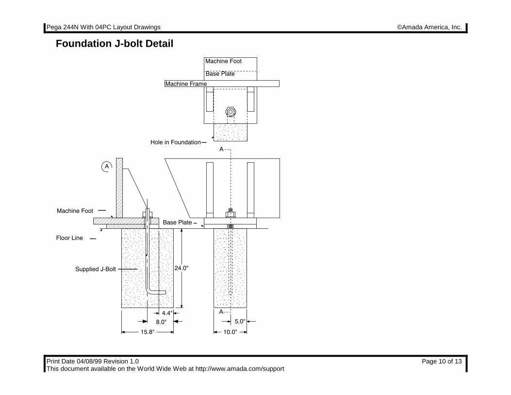
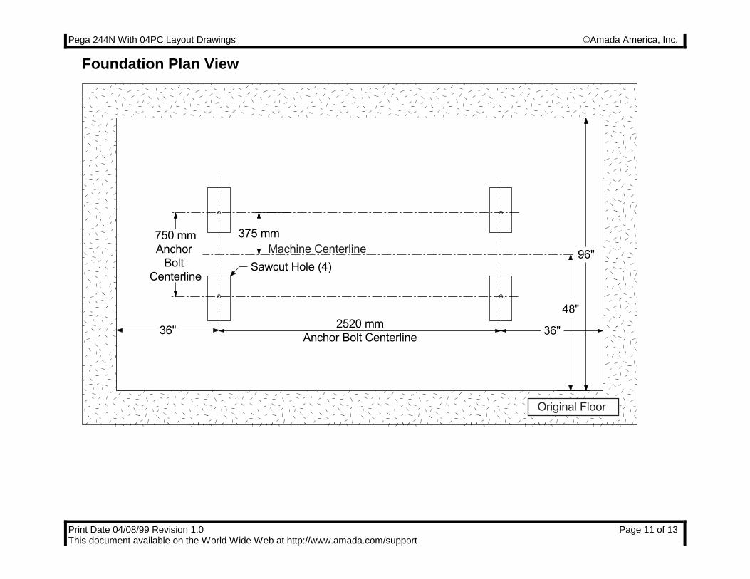
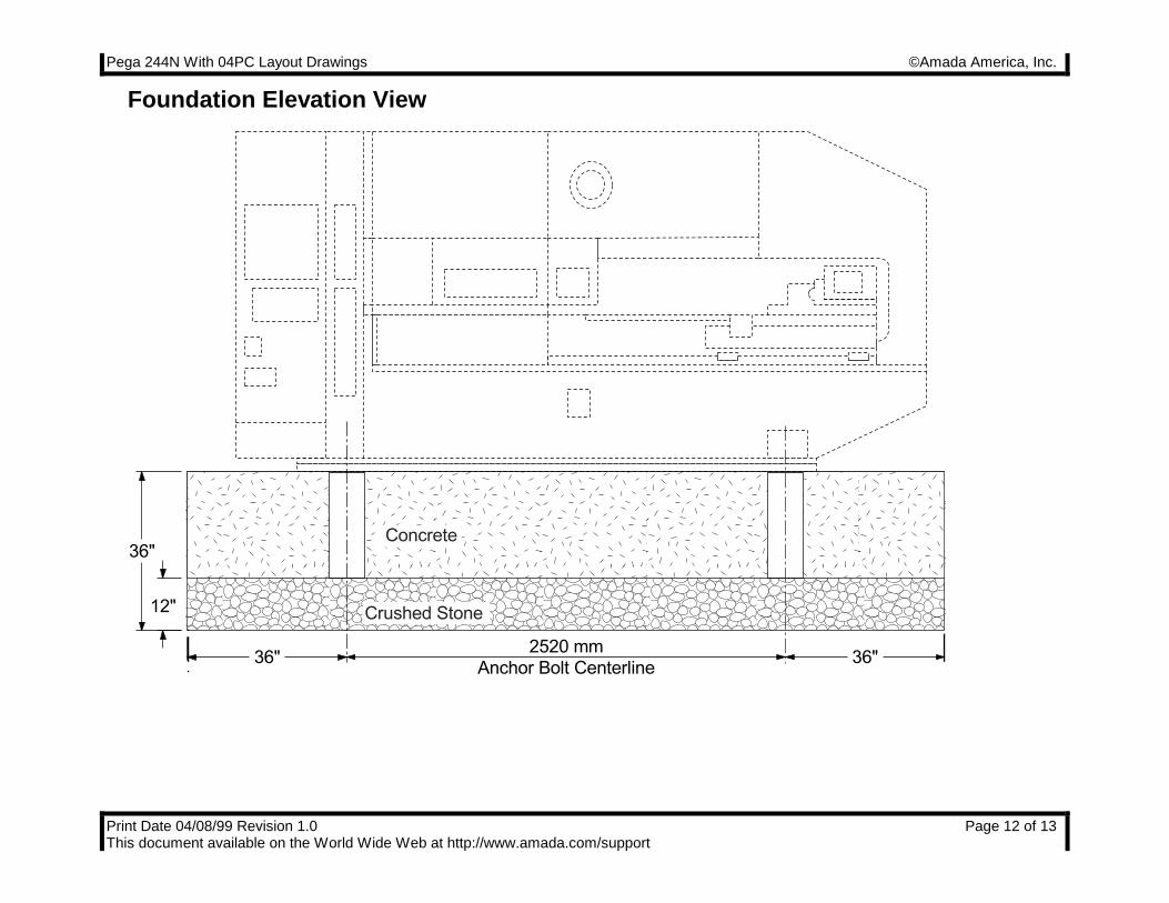
Foundation RequirementsThe Pega 244N does not require a special foundation to perform as expected, however there are minimum requirementsthat an existing floor must meet in order to assure machine reliability and tool life. If the existing floor does not meet thefollowing minimum requirements, plans for a recommended foundation are given in the section Foundation AnchoringProcedure
The minimum acceptable floor conditions to assure a successful installation are:
The area of the floor where the machine frame is to be located must be a single, homogeneous slab in good condition.There must be no cracks or other signs of deterioration of the floor.
The floor must be 4" to 6" thick.
The floor must be capable of supporting 3.5 tons/ft².
The floor must be level to 0.032"/ft.
If the existing floor meets the minimum requirement list above, it must still be inspected carefully when the anchor-boltholes are cut. Voids under the floor, or wetness (not associated with the hole cutting procedure) should be consideredsigns of an inadequate floor and a new machine location or new foundation must be considered.
It is the customer’s responsibility to determine that the floor meets these minimum requirements. Placing the machine onan inadequate, cracked floor, or straddling seams in a floor may be grounds for voiding the machine warranty!
©Amada America, Inc. does not recommend the use of vibration isolating mounts under the machine feet, as thesedevices have been shown to increase the vibration within the machine frame, increasing the likelihood of vibration relatedproblems. Solid leveling devices are acceptable provided they incorporate a means of anchoring the machine to the floorwith the supplied J-bolts.
Pega 244N With 04PC Layout Drawings ©Amada America, Inc.
Print Date 04/08/99 Revision 1.0 Page 10 of 13This document available on the World Wide Web at http://www.amada.com/support
Foundation J-bolt Detail
��@@��ÀÀ��@@��ÀÀ��@@��ÀÀ��@@��ÀÀ��@@��ÀÀ��@@��ÀÀ��@@��ÀÀ��@@��ÀÀ��@@��ÀÀ��@@��ÀÀ��@@��ÀÀ��@@��ÀÀ��@@��ÀÀ��@@��ÀÀ��@@��ÀÀ��@@��ÀÀ��@@��ÀÀ��@@��ÀÀ��@@��ÀÀ��yy�@�À�@�À�@�À�@�À�@�À�@�À�@�À�@�À�@�À�@�À�@�À�@�À�@�À�@�À�@�À�@�À�@�À�@�À�@�À�y���@@@���ÀÀÀ���@@@���ÀÀÀ���@@@���ÀÀÀ���@@@���ÀÀÀ���@@@���ÀÀÀ���@@@���ÀÀÀ���@@@���ÀÀÀ���@@@���ÀÀÀ���@@@���ÀÀÀ���@@@���ÀÀÀ���@@@���ÀÀÀ���@@@���ÀÀÀ���@@@���ÀÀÀ���@@@���ÀÀÀ���@@@���ÀÀÀ���@@@���ÀÀÀ���@@@���ÀÀÀ���@@@���ÀÀÀ���@@@���ÀÀÀ���yyy���
@@@
���
ÀÀÀ
���
@@@
���
ÀÀÀ
���
@@@
���
ÀÀÀ
���
@@@
���
ÀÀÀ
���
@@@
���
ÀÀÀ
���
@@@
���
ÀÀÀ
���
@@@
���
ÀÀÀ
���
@@@
���
ÀÀÀ
���
@@@
���
ÀÀÀ
���
@@@
���
ÀÀÀ
���
@@@
���
ÀÀÀ
���
@@@
���
ÀÀÀ
���
@@@
���
ÀÀÀ
���
@@@
���
ÀÀÀ
���
@@@
���
ÀÀÀ
���
@@@
���
ÀÀÀ
���
@@@
���
ÀÀÀ
���
@@@
���
ÀÀÀ
���
@@@
���
ÀÀÀ
���
yyy
������������
yyyyyyyyyyyy
��������
yyyyyyyy
����yyyy
Pega 244N With 04PC Layout Drawings ©Amada America, Inc.
Print Date 04/08/99 Revision 1.0 Page 11 of 13This document available on the World Wide Web at http://www.amada.com/support
Foundation Plan View
96"
48"
36"36"
Sawcut Hole (4)
375 mm750 mm
Anchor
Bolt
Centerline
2520 mm
Anchor Bolt Centerline
Machine Centerline
Original Floor
Pega 244N With 04PC Layout Drawings ©Amada America, Inc.
Print Date 04/08/99 Revision 1.0 Page 12 of 13This document available on the World Wide Web at http://www.amada.com/support
Foundation Elevation View
36"
12"
36"36"2520 mm
Anchor Bolt Centerline
Crushed Stone
Concrete
Pega 244N With 04PC Layout Drawings ©Amada America, Inc.
Print Date 04/08/99 Revision 1.0 Page 13 of 13This document available on the World Wide Web at http://www.amada.com/support
Turret 740mm Disk Thick 24 Station 2 Auto Index
201302
303
204
205
206307
308209
310 211
312 213314
315
216
217
218 319
320221
322223
324
24 Station2 Auto Index
A
B
C
D
B
1¼"
1¼"
½"
3½"
2"
12.7mm
31.7mm
50.8mm
88.9mm
31.7mm
12 (6)
6 (6)
2 (2)
2 (2)
1 (1)
Maximum �
Size Round
Number
Of Stations
(Keyed)
Auto Index
This turret configuration
used on the following machine models
Pega 244