EUROCONTROL Doc. No.: PEG-SUM-DYN Aircraft Dynamics Module Issue: A Date: 17/06/2003 Project: PEGASUS Software User Manual Sheet 1 of 26 Title: PEGASUS Software User Manual Aircraft Dynamics Module Prepared by: IfEN/M3S MARS-2 Team Date: 15/05/2003 Checked by: GNSS Tools Review Team Distribution: PEGASUS development team EEC/GNSS Software Engineering Unit EEC/SEU GBAS Project EEC/GNSS This document and the information therein is the property of Eurocontrol. It must not be reproduced in whole or in part or otherwise disclosed without prior written consent of the Director Eurocontrol Experimental Centre. The contents of this document only expresses the opinions of the author and does not necessarily reflect the official views or policy of the Agency.
Transcript
EUROCONTROL Doc. No.: PEG-SUM-DYN
Aircraft Dynamics Module Issue: A Date: 17/06/2003Project:
PEGASUS
Software User Manual Sheet 1 of 26
Title: PEGASUS
Software User Manual
Aircraft Dynamics Module
Prepared by: IfEN/M3S MARS-2 Team Date: 15/05/2003
Checked by: GNSS Tools Review Team
Distribution: PEGASUS development team EEC/GNSSSoftware Engineering Unit EEC/SEUGBAS Project EEC/GNSS
This document and the information therein is the property of Eurocontrol. It must not be reproduced in whole or in part or otherwise disclosed without prior written consent of the Director Eurocontrol Experimental Centre.
The contents of this document only expresses the opinions of the author anddoes not necessarily reflect the official views or policy of the Agency.
EUROCONTROL Doc. No.: PEG-SUM-DYN
Aircraft Dynamics Module Issue: A Date: 17/06/2003Project:
PEGASUS
Software User Manual Sheet 2 of 26
Change Record
Issue Date Chapter Description of Changes
1- 16/05/2003 All First Issue, Software Version 1.2
A 17/06/2003 All Relabeling and minor editorial corrections forPEGASUS release
EUROCONTROL Doc. No.: PEG-SUM-DYN
Aircraft Dynamics Module Issue: A Date: 17/06/2003Project:
1.3. Purpose...............................................................................................................................................61.3.1. Purpose of the Document ............................................................................................................61.3.2. Purpose of the Module .................................................................................................................6
4. PROBLEM REPORTING INSTRUCTIONS............................................................................... 11
5. GENERAL USE.............................................................................................................................. 12
5.1. Graphical Interface .........................................................................................................................125.1.1. Main Dialog Window..................................................................................................................12
5.2. Step-by-step Overview..................................................................................................................135.2.1. Start and Initialise M4 Software.................................................................................................13
EUROCONTROL Doc. No.: PEG-SUM-DYN
Aircraft Dynamics Module Issue: A Date: 17/06/2003Project:
PEGASUS
Software User Manual Sheet 4 of 26
5.2.2. Selection of calculation to process ...........................................................................................145.2.3. Selection of Input and Output Files............................................................................................145.2.4. Interpolation configuration..........................................................................................................155.2.5. Filter description file specification ............................................................................................165.2.6. Lever-arm and G-force configuration........................................................................................165.2.7. Selection of output files prefix....................................................................................................175.2.8. Start and Check Processing......................................................................................................175.2.9. About Aircraft Dynamics ............................................................................................................19
5.3. Help ....................................................................................................................................................19
5.4. Operating Modes.............................................................................................................................195.4.1. The Embedded Mode ................................................................................................................195.4.2. The Command-Line Mode.........................................................................................................20
Aircraft Dynamics Module Issue: A Date: 17/06/2003Project:
PEGASUS
Software User Manual Sheet 5 of 26
EUROCONTROL Doc. No.: PEG-SUM-DYN
Aircraft Dynamics Module Issue: A Date: 17/06/2003Project:
PEGASUS
Software User Manual Sheet 6 of 26
1. IntroductionThis document is the User Manual of the Aircraft Dynamics module for the PEGASUSSoftware Version 3.0. It provides all information needed to install and use this module.
1.1. Intended ReadershipPlease refer to the Main Software User Manual for PEGASUS [3].
1.2. Applicability Statement
This Software User Manual is to be used as reference for the version 1.2 of thePEGASUS Aircraft Dynamics Module. Each reference to the current version ofPEGASUS in this document is a reference to version 3.0.
As the PEGASUS software is based on integration of individual modules, the fulldocumentation contains multiple PEGASUS module documentation items. To profitfrom the modular structure of the software, this version of the Software User Manualcontains references to the relevant main Software User Manual only. It should be used inconjunction with the other User Manuals referenced in that main User Manual.
1.3. Purpose
1.3.1. Purpose of the Document
This document contains the necessary information related to the use of the PEGASUSModule Dynamics .It describes the installation and de-installation procedures, the different functionalities ofthe module, as well as what the user has to do in order to perform the individualprocessing tasks.
1.3.2. Purpose of the Module
The Dynamics module main functionality is the calculation of path error (NSE, FTE, TSE)and associated statistics. It also supports meteorological data and aircraft dynamics(acceleration and ground speed) surveying.
1.4. Document Structure
This manual shall be used as reference for the use of the PEGASUS Module AircraftDynamics .
EUROCONTROL Doc. No.: PEG-SUM-DYN
Aircraft Dynamics Module Issue: A Date: 17/06/2003Project:
PEGASUS
Software User Manual Sheet 7 of 26
Section 1: Introduction contains a brief introduction to the PEGASUS software.
Section 2: Overview contains a general description of the module functionality.
Section 3: Installation describes the procedures needed to install the module on anew machine.
Section 4: Problem Reporting contains information on additional means to obtainsupport on the software and provides points of contact for the reporting of issues linkedto the use of the software.
Section 5: General Use gives a step-by-step introduction to the module
Section 6: Services contains a more detailed presentation of the possible functionalityof the module, describing the necessary input data, user actions and the obtainedresults. It is designed as a reference section.
Appendix A contains a list of error messages that might be encountered by using themodule, together with the procedures to apply for correction.
Appendix B provides an example of an dynamics.ini file.
Appendix C is a glossary of all the terms in use within this Software User Manual.
1.5. Related Documents
[1] MARS-2 Technical Note, Doc.-No. PEG-TN-MARS2, current issue
[2] MARS-2 PEGASUS Interface Control Document Addendum, Doc.-No. PEG-ICD-01Add, current issue
[3] "Software User Manual", EEC PEGASUS User Manual PEGSUM-01 current issue
[4] “Visualisation Routines Software User Manual”, EEC PEGASUS, PEG-SUM-VIS current issue
1.6. Reference Documents:
[R1] “Guide to applying the ESA software engineering standards to small software projects”, ESA,BSSC(96)2 Issue 1
[R2] Eurocontrol Experimental Centre Software Engineering Unit (SEU)
This Software User Manual corresponds to the user part of the PEGASUSdocumentation set.
EUROCONTROL Doc. No.: PEG-SUM-DYN
Aircraft Dynamics Module Issue: A Date: 17/06/2003Project:
PEGASUS
Software User Manual Sheet 8 of 26
2. Overview
2.1. Objectives
2.1.1. Concepts
The Aircraft Dynamics module aims at analysing on board recorded approach flight trials.
2.1.2. Approach
Aircraft dynamics module main functionality is the calculation of error and associatedstatistics (NSE, FTE, TSE). It provides as well results concerning aircraft dynamicsexceeding limitations and meteorological related results.
This module was realised in the context of the GBAS-MARS 2 program in order to analyseGBAS CAT 1 approaches but performance analysis enable to consider possible extensionto CAT 2 and 3 (lever-arm and G-force corrections are performed).
The module interfaces with PEGASUS component, notably “Convertor”, “WinGPSAll”,“CarrierPhase” and “Procedure Visualisation” modules.
2.2. Components
The Aircraft Dynamics module consists of four parts
1. The GUI executable for integration (dynamics.exe)
2. The core processing module (dynamicsproc.exe)
3. The visualisation scripts, called from the M-File runner module
4. The GUI dll for PEGASUS integration (dynamics.dll)
This SUM just covers the GUI (dynamics.dll and dynamics.exe).
EUROCONTROL Doc. No.: PEG-SUM-DYN
Aircraft Dynamics Module Issue: A Date: 17/06/2003Project:
PEGASUS
Software User Manual Sheet 9 of 26
3. Installation
3.1. System Requirements
3.1.1. Hardware
This section describes only requirements differing from those in the main User Manual[3]
3.1.2. Software
This section describes only requirements differing from those in the main User Manual[3].
3.2. Installation ProcedureThis section describes only the procedure for stand-alone use.
Currently no automatic installation procedure is provided to install the differentcomponents.
Therefore the different parts have to installed manually by copying the deliveredcomponents. Special directory structures have not to be taken into account.
In case that the Dynamics Module is foreseen to be run embedded in the PEGASUSframework, the following components should be installed into the same directorystructure as PEGASUS ([PPlus] refers to the installation directory of PEGASUS):
Aircraft Dynamics Module Issue: A Date: 17/06/2003Project:
PEGASUS
Software User Manual Sheet 10 of 26
The “dynamics.ini” file will be provided with default values. If no ‘ini’ file is specified ascommand line argument, the dynamics.exe will search for the dynamics.ini in theinstallation directory. If not available, default parameter values will be used (specifiedinside the software).
After installation of the dynamics.exe core program, the user will see the following iconin the Windows explorer (large symbol view):
Figure 3.2-1: dynamics.exe program icon
Double-click on this icon will start the dynamics.exe.
The same icon can be seen from the ‘Standalone’ part of the PEGASUS frameworkprogram (which allows start of the dynamics.exe in standalone mode from inside thePEGASUS framework).
3.3. De-installation ProcedureThis section describes only the procedure for stand-alone use.
In order to completely uninstall the software all installed files have to be deleted. As themodule do not generate any entries into the ‘Windows system registry’, there are noother delete actions necessary.
EUROCONTROL Doc. No.: PEG-SUM-DYN
Aircraft Dynamics Module Issue: A Date: 17/06/2003Project:
PEGASUS
Software User Manual Sheet 11 of 26
4. Problem Reporting InstructionsPEGASUS is a software prototype under development for Eurocontrol in support of theSBAS and GBAS activities. The Eurocontrol Experimental Centre has been defined asa focal point for User Feedback Reporting.Today a web-site for PEGASUS is already operational inside the Eurocontrol GNSS-Programme SBAS Project web-site and can be consulted for questions related to thesoftware: http://www.eurocontrol.fr/projects/sbas/pegasus/
The different steps in problem investigation should be the following:
1) Use of information in the documents provided:• This User Manual for software operation issues ;• The Error Recovery Procedures in Annex A of this Manual for operating errors
and warnings;• The ICD [2] for issues related to data formats and parameter limitations;• The Technical Note [1] for issues related to the algorithms employed for
processing.
2) Review of the information provided on the website cited above, especially the“Frequently Asked Questions”.
3) Establishing contact with the development team via the following methods (explainedin more detail in the main User Manual [3]):• E-mail: [email protected] (preferred)• Fax: +33-1-6988-7307 (in exceptional cases)
EUROCONTROL Doc. No.: PEG-SUM-DYN
Aircraft Dynamics Module Issue: A Date: 17/06/2003Project:
PEGASUS
Software User Manual Sheet 12 of 26
5. General Use
The following chapters give an overview how to use the Aircraft Dynamics module.
As the usage of the Aircraft Dynamics module is foreseen just for one straightforward task,the general use is very simple:
• Start the dynamics.exe (embedded or standalone)
• Provide the necessary input data using a dynamics type ini file (see Annex B). Thecontents of this ini file can be either edited using the PEGASUS framework (using thedynamics.exe) or the Aircraft Dynamics module main window.
• ‘Start’ processing via control or automatic (in embedded mode)
• ‘Stop’ processing manually or wait until the complete input files are processed and outputfiles are generated.
5.1. Graphical InterfaceThe following section provides an overview of the graphical user interface of the module.
5.1.1. Main Dialog Window
Initialisation and configuration of Aircraft Dynamics module is performed using the mainGUI presented in Figure 5.1-1. The different sections in GUI are grouped and numbered.Description of the steps (Section 5.2) correspond to the numbers over impressed in thefigure.
Select calculation to process 1
2 3
4 6 5
8
7
Select input files
Select interpolation order
Select PFE/CMN filter description files
Configure Lever-Arm and G-force parameters
Select output files prefix
Click on start button
Click on exit button
Figure 5.1-1: M4 main window in standalone mode
From the main window the 8 different parts can be seen:
EUROCONTROL Doc. No.: PEG-SUM-DYN
Aircraft Dynamics Module Issue: A Date: 17/06/2003Project:
PEGASUS
Software User Manual Sheet 13 of 26
1. Selection of calculation to process
2. Selection of input files
3. Selection of interpolation order
4. Selection of PFE/CMN filter characteristics
5. Configuration of Lever-arm and G-force parameters
6. Selection of output file name and path
7. Start Button
8. Exit Button
The log tab gives feedback on the processing being done by the module.
The error tab presents errors or warnings issued by the module during the processing.
5.2. Step-by-step OverviewIn the following sections the main steps ‘how-to-use’ the dynamics.exe software instandalone mode are described.
5.2.1. Start and Initialise M4 Software
In general the dynamics.exe core module will be started manually by double-clicking thedynamics.exe (then the main dialog window of Figure 5.1-1 appears on the screen) orfrom inside the PEGASUS framework.
In any case, the framework/user can determine the behavior of the Aircraft Dynamicsmodule through 2 ‘command line’ parameters:
dynamics.exe [-b] [-ini xxx:ini]
The [-b] option determines, whether the module is running embedded (command [-b] isgiven in command line) or standalone (no option). Usually the [-b] option is used whencalled from the PEGASUS framework.
The second option [-ini xxx.ini] tells the dynamics.exe, that a ‘xxx.ini’ file shall be used. Thexxx means that every name can be used here for the ‘ini’ file. The ‘ini’ determines allnecessary data for processing.
When the dynamics module is running embedded ([-b] is given at command line), also theprovision of a valid [-ini xxx.ini] command option is mandatory (the data from the ‘ini’ file arenecessary to initialize all necessary processing input data). If the second option is notprovided, the dynamics module will terminate.
If running standalone, the provision of a ‘xxx.ini file is not mandatory. As the user has theoption to set necessary processing data from the dialog window. However as a standard,the module will look for a ‘dynamics.ini’ in the installation directory. If it is found, this ‘ini’ filewill be used.
EUROCONTROL Doc. No.: PEG-SUM-DYN
Aircraft Dynamics Module Issue: A Date: 17/06/2003Project:
PEGASUS
Software User Manual Sheet 14 of 26
If no ‘ini’ file is available, default values will be used as far as possible for the processing.But at least the input data files must be selected.
5.2.2. Selection of calculation to process
The user chooses which calculation he wants the module to perform as depicted in Figure5.1-1. These check boxes determines the behaviour of the module. For example, if the userclick on the NSE check box, the “AFP” and “NSFP” Input file names must be provided tomodule (see next section for configuration of input file names).
• NSE: Navigation System Error, needs AFP and NSFP input data files.
• TSE: Total System Error, needs AFP and DFP input data files.
• FTE: Total System Error, needs NSFP and DFP input data files.
• PFE: Path Following Error is calculated upon either TSE or FTE, it needs the PFE filterdescription file (a default file is provided ).
• CMN: Control Motion Noise is calculated upon either TSE or FTE, it needs the CMN filterdescription file (a default file is provided ).
• DYN: Needs the Aircraft input data file for extracting dynamics information (accelerationand ground speed).
• MTO: Meteorological data are processed by the module, it needs the Aircraft input datafile.
The “ALL” check box have a special behaviour, it enables or disables all other checkboxes.
5.2.3. Selection of Input and Output Files
Independent of embedded/standalone mode, the selection of the input processing files isthe most important step.
Depending on the calculation chosen by the user in step 1, the module needs one or moreinput files :• “AFP” is the actual flight path. This file is normally provided by the “CarrierPhase” module
or any other external truth reference. This file is needed for the NSE and TSE checkboxes.
• “NSFP” is the Navigation System Flight Path. This file is normally provided by the“WinGPSall” module but it can also accepted a 1Hz data file from the “Convertor”module. This file is needed for the NSE and FTE check boxes.
• “DFP” is the procedure description file. This file is normally provided by the “ProcedureVisualisation” module but it can also be a user-written file. This file is needed for the TSEand FTE check boxes.
• “.1Hz” is the aircraft data file normally provided by the “Convertor” module. This file isneeded for the DYN and MTO check boxes but also if Lever-arm corrections are to beapplied on the AFP and NSFP data files.
EUROCONTROL Doc. No.: PEG-SUM-DYN
Aircraft Dynamics Module Issue: A Date: 17/06/2003Project:
PEGASUS
Software User Manual Sheet 15 of 26
In general the name of the input file will be selected by the user inside the ‘File I/O’ groupbox using the ‘Input Files’ edit fields. If the user does not want to type path and name of theinput files, it is also possible to select the right file using the ‘Button’ right to the edit field(see next figure). This selection of input file name is mandatory.
Figure 5.2-1: Select Input File Path and Name (here under Windows NT)
From the selected file, just the file name without extension is used. For dynamics, no inputfile is mandatory but GBAS messages and obstacles visualization necessitate to enterinput files (.csv format) .
In case of embedded processing inside the PEGASUS framework, the framework willprovide the user the input selection edit box and file browsing capability. The selected filename is than written (using the dynamics.ini) to a ‘xxx.ini’ file. Finally the framework will startthe dynamics.exe with the ‘xxx.ini’ as argument on the command line.
For the output file, the user also can write a filename in the ‘Output File’ edit box (or usingthe browsing capability via the button right of the output edit field).
In case the user just gives a name without path, dynamics.exe will search the file in theinstallation directory.
When no output file name and path is specified, the output will be written also to theinstallation directory.
5.2.4. Interpolation configuration
The user has the choice between three type of interpolation:
• None: No interpolation performed.
• Linear: First order interpolation.
• Higher order: Higher order interpolation.
EUROCONTROL Doc. No.: PEG-SUM-DYN
Aircraft Dynamics Module Issue: A Date: 17/06/2003Project:
PEGASUS
Software User Manual Sheet 16 of 26
The user then should choose the maximum de-synchronisation between two data sets (MaxDT). A value between 0 and 1s is allowed but a value greater than 0.3 is notrecommended. The user can either write directly the “Max DT” edit box or use the Up andDown arrow to fix it to the desired value. A value of zero mean that no interpolation will beperformed.
5.2.5. Filter description file specification
Two default files are provided in the “dynamics” directory:
• “dynamics\cmn_filter.ini” : file containing the description of the default band-passfilter needed to calculate the CMN.
• “dynamics\pfe_filter.ini” : file containing the description of the default low-pass filterneeded to calculate the PFE.
If the user wants to provide alternate filter description files, those should respect the formatdefined in [2] and explained in [1].
5.2.6. Lever-arm and G-force configuration
By default, no lever-arm and G-force correction is performed unless this button is clicked. Ifthe user click on it, a pop-up window as depicted in Figure 5.2-2 will be shown to the userwhere he can specify:
• the 3 co-ordinates of the static (on-ground) position of the centre of gravity,
• the 3 co-ordinates of the static (on-ground) lever-arm to apply to AFP, NSFP and INS,
• the five coefficients K0 to K4 needed to model the G-force correction.
All the edit boxes are empty by default. They must be filled up and the X value of the centreof gravity has to be set to a greater than zero value if lever-arm and G-force corrections areto be performed. If any of the edit boxes is empty or if the X value of the centre of gravityhas a lower than or equal to zero value, then no correction and a warning will be producedat run-time.
EUROCONTROL Doc. No.: PEG-SUM-DYN
Aircraft Dynamics Module Issue: A Date: 17/06/2003Project:
PEGASUS
Software User Manual Sheet 17 of 26
Figure 5.2-2 – Lever-arm and G-force configuration
Please see [1] section 6.4.3 and 6.4.4 for further understanding of this issue.
5.2.7. Selection of output files prefix
The user can choose a directory by clicking on the directory selector […] button andcomplete it by a name that will be used to prefix output file names. The “Dynamics” modulewill output one to four data files depending on user configuration options. These files will beprefixed by the name shown in this edit box.
5.2.8. Start and Check Processing
The processing is started when the user click on the “start” button which then transformsitself into a “stop” button and again into a “start” button when the processing is finished. Ifthe user click on the “stop” button, the processing is prematurely stopped.
The user can exit the application by clicking on the Exit button.
By clicking on the “Log” tab, a new view is offered the user as shown in Figure 5.2-3. Thiswindows gives feedback on the processing being done by the module. The user can switchbetween the Configuration GUI and the Log window during the processing.
EUROCONTROL Doc. No.: PEG-SUM-DYN
Aircraft Dynamics Module Issue: A Date: 17/06/2003Project:
PEGASUS
Software User Manual Sheet 18 of 26
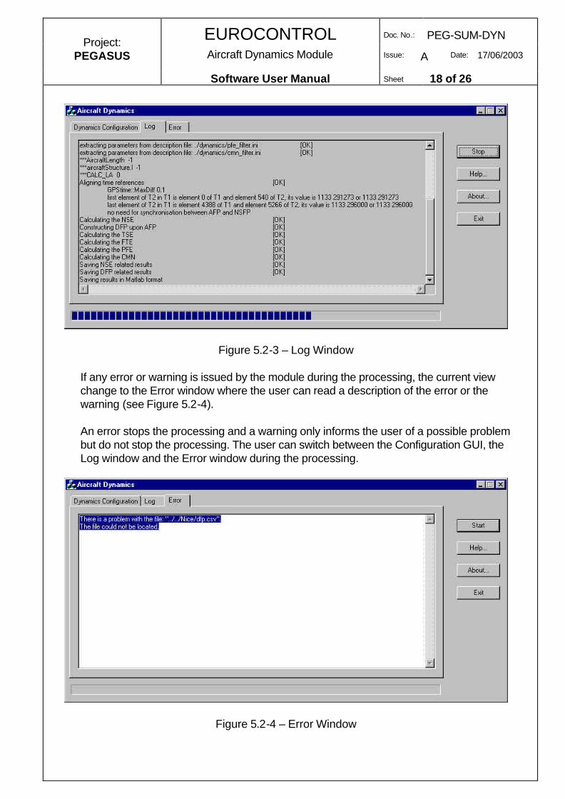
Figure 5.2-3 – Log Window
If any error or warning is issued by the module during the processing, the current viewchange to the Error window where the user can read a description of the error or thewarning (see Figure 5.2-4).
An error stops the processing and a warning only informs the user of a possible problembut do not stop the processing. The user can switch between the Configuration GUI, theLog window and the Error window during the processing.
Figure 5.2-4 – Error Window
EUROCONTROL Doc. No.: PEG-SUM-DYN
Aircraft Dynamics Module Issue: A Date: 17/06/2003Project:
PEGASUS
Software User Manual Sheet 19 of 26
5.2.9. About Aircraft Dynamics
By pushing the ‘About’ button of the ‘Control’ group, a information dialog will be shown tothe user, providing information concerning version, copyright and purpose of the software(see next figure):
Figure 5.2-5: About M4 module
5.3. Help
In addition to this Software User Manual, a Helpdesk covering all the aspects of the toolis available. The can be activated by clicking on the ‘Help’ button of the commandcontrol group of the main user interface.
5.4. Operating ModesEach Module for PEGASUS must be able to be operated in three modes:
1. As stand-alone executable2. Embedded in the PEGASUS frame3. In command-line Mode
While the stand-alone mode is described as the baseline mode in this User Manual, thetwo following sections describe the specific elements of operation in the other twomodes.
5.4.1. The Embedded Mode
When the module is running in the embedded mode, i.e. called by the PEGASUSframework, it allows parameter values to be set from inside the framework. That means thatonly the parameter GUI part of the module software is visible in the parameter selectionwindow of the Frame GUI. The Frame will automatically create the INI-File which is passedthen as a command line argument to the core module processing executable, containing theselections made inside the framework. Equally, the invocation of the module processing isautomatic through the Scheduler provided in the Frame. Detailed descriptions of this
EUROCONTROL Doc. No.: PEG-SUM-DYN
Aircraft Dynamics Module Issue: A Date: 17/06/2003Project:
PEGASUS
Software User Manual Sheet 20 of 26
mechanism and a short description of the module GUI in Embedded Mode are contained inthe main User Manual [3].
5.4.2. The Command-Line Mode
The core processing functions of the Module can be started in command line mode bytyping:
<Module Name>.exe [-b] [-ini xxx:ini]
The [-b] option instructs the software not to display the GUI and to take all the inputs from anINI-file provided. The –ini option is mandatory if the –b option is used, if no valid INI-file isprovided, the module execution will terminate.
Usually the [-b] option is used when called by the scheduler from the PEGASUS framework.
The option [-ini xxx.ini] tells the executable, that the ‘xxx.ini’ file shall be used. The xxx standsfor an user-defined name for the ‘ini’ file. It must contain all necessary data for processing.This option may also be used without the –b option, to invoke the GUI with pre-definedsettings that can be changed interactively.
EUROCONTROL Doc. No.: PEG-SUM-DYN
Aircraft Dynamics Module Issue: A Date: 17/06/2003Project:
As described in Section 5.2.2, the user has to define the calculations to be performed.
6.1.3. Output Data
The “Dynamics” module will output one to four data files depending on user configurationoptions, these files are prefixed with the prefix configured in the output file prefix selector(see § 5.2.7):
[prefix]_nse.csv : CSV file containing NSE related results
[prefix]_dfp.csv : CSV file containing approach related results: TSE, FTE, CMN and PFE,…
[prefix]_mto.csv : CSV file containing meteorological related results: Pressure andTemperature,…
Please see [2] section 5.3 for further details about these files.
6.2. Service 2 : Visualise Paths
6.2.1. Input Data
Synchronised paths : afp.csv, dfp.csv, nsfp.csv
6.2.2. Options
The graphical visualisation options are available after processing by the plottingroutines [4].
6.2.3. Output
Create a 2D graphical display for all paths (AFP, DFP and NSFP) :
• Latitude vs. Longitude• Altitude vs. Latitude
EUROCONTROL Doc. No.: PEG-SUM-DYN
Aircraft Dynamics Module Issue: A Date: 17/06/2003Project:
PEGASUS
Software User Manual Sheet 22 of 26
• Altitude vs. Longitude• Altitude vs. Distance to threshold
6.3. Service 3 : Visualise Path Errors
6.3.1. Input Data
[prefix]_nse.csv : CSV file containing NSE related results
[prefix]_dfp.csv : CSV file containing approach related results: TSE, FTE, CMN and PFE,…
6.3.2. Options
The graphical visualisation options are available after processing by the plottingroutines [4].
6.3.3. Output
• Create a graphical time plot display for all errors (NSE, FTE, TSE, CMN, PFE).• Create a graphical display for statistics of all errors.• Create a graphical display for CMN and PFE spectral analysis.
The graphical visualisation options are available after processing by the plottingroutines [4].
6.4.3. Output
Create a graphical display for detection of aircraft dynamics exceeding pre-defined limits
6.5. Service 5 :Visualise Meteorological data
6.5.1. Input Data
[prefix]_mto.csv : CSV file containing meteorological related results: Pressure andTemperature,…
EUROCONTROL Doc. No.: PEG-SUM-DYN
Aircraft Dynamics Module Issue: A Date: 17/06/2003Project:
PEGASUS
Software User Manual Sheet 23 of 26
6.5.2. Options
The graphical visualisation options are available after processing by the plottingroutines [4].
6.5.3. Output
Create a graphical display of the aircraft collected meteorological parameters.
EUROCONTROL Doc. No.: PEG-SUM-DYN
Aircraft Dynamics Module Issue: A Date: 17/06/2003Project:
PEGASUS
Software User Manual Sheet 24 of 26
Appendix A: Error messages and recovery procedures
Whenever the program exits abnormally it will exit with a certain value. Some of these exitcodes are already defined in the Pegasus framework :
Exitcode
definition
0 everything is fine1 error in command line syntax2 can't find ini file3 error in ini file (bad data)4 no input file specified5 can't find specified input file6 can't write output file7 missing or inconsistent settings - can't start8 missing or inconsistent data9 out of memory10 undefined error
Additionally, the following error messages will be written during the processing of input dataand in the log file. The column “Exit Code” refers to the corresponding exit code of theprogram if relevant, if not the cell is left blank.
ID ExitCode
Error message Solution
1 6 The output file has not been created See log file2 5 The file could not be located Input file could not be opened. Ensure that
input file is available3 6 The file is already open by another
processClose the other process
4 There is a problem with this file An additional message will be written5 5 All or part of the path is invalid Ensure that the path is correct6 5 There is an unknown problem with the
fileInput file could not be opened. Ensure thatinput file is available
7 2 No ini file found Provide correct ini file on command line inembedded mode
Additionally information messages will be provided. But they are not provided in the table above.
EUROCONTROL Doc. No.: PEG-SUM-DYN
Aircraft Dynamics Module Issue: A Date: 17/06/2003Project:
PEGASUS
Software User Manual Sheet 25 of 26
Annex B Initialisation file exampleThe following ini file is part of the Dynamics module provided files. It contains typicaldefault values:
Aircraft Dynamics Module Issue: A Date: 17/06/2003Project:
PEGASUS
Software User Manual Sheet 26 of 26
Appendix C: Glossary
This appendix contains the list of all the specialised terms used within this SoftwareUser Manual, together with their definition.
ADD Architectural Design DocumentAFP Actual Flight PathASCII American Standards Committee for Information InterchangeCMN Control Motion NoiseDFP Desired Flight PathDLL Dynamic Link LibraryDO DocumentEEC EUROCONTROL Experimental CentreEGNOS European Geostationary Navigation Overlay ServiceGBAS Ground-Based Augmentation SystemGNSS Global Navigation Satellite SystemGPS Global Positioning SystemGUI Graphical User InterfaceICD Interface Control DocumentID IdentifierIFEN IfEN GmbHINS Inertial Navigation SystemM3S M3 SystemsMARS Modular Analysis and Research SystemNED North/East/DownNSE Navigation System ErrorNSFP Navigation System Flight PathPEGASUS Prototype EGNOS and GBAS Analysis System Using SAPPHIREPFE Path Following ErrorRLD Rear Left DownSAPPHIRE Satellite and Aircraft Database Project for System Integrity ResearchSBAS Satellite-Based Augmentation SystemTSE Total System ErrorWGS World Geodesic System