Page 1
The magazine for the international power industry November 2014
SAFETY MEASURES FOR COAL PLANTS
TIPS FOR SELECTING THE RIGHT DRIVE
NEW SOLUTION FOR GRID FLEXIBILITY
NORTH AMERICA’S DRIVE TO CUT CO2
www.PowerEngineeringInt.com
1411PEI_C1 1 11/10/14 9:54 AM
Page 2
Introducing the QSK95 Series of high-horsepower generator sets.
When it comes to power generation, more is better. More horsepower.
More performance. More reliability. But what if you could also have a
generator set that takes up less space in your facility, lowers installation
costs and reduces maintenance? At Cummins Power Generation, we
call this The Power of More — and with the QSK95 Series of generator
sets, it can be yours. Rated at up to 3,500 kW (3,750 kVA) and designed
with a smaller footprint, the QSK95 delivers the highest kilowatt per
square foot ratio in its class.
The Power of More.
Our energy working for you.TM
© 2014 Cummins Power Generation Inc. All rights reserved. Cummins Power Generation and Cummins are registered trademarks of Cummins Inc. “Our energy working for you.” is a trademark of Cummins Power Generation Inc.
Visit our website to see how the QSK95
can give you The Power of More.
CumminsPowerOfMore.com/QSK95Series
For more information, enter 1 at pei.hotims.com
1411PEI_C2 2 11/10/14 9:54 AM
Page 3
1
POWER ENGINEERING INTERNATIONAL
Contents
Free Product InfoYou can request product and service information from this issue. Simply click on the link below that will provide you access to supplier companies’ websites,
product information and more http://pei.hotims.com
If you are considering suppliers or buying products you read about in PEi, please use this service. It gives us an idea of how products are being received to help us continually
improve our editorial offering and it also lets our advertisers know that you are a PEi reader and helps them to continue supporting the free distribution of your magazine.
On the cover Increasingly fast and sophisticated real-time plant analysis software is unlocking improved predictability, reliability and fexibility for combined-
cycle plant - p6. Cover image credit: Siemens
Features
6 The rise of the digital power plant
How real-time analysis and simulation software is bringing
operational benefts for combined-cycle plants.
12 Driving a low-carbon path for American power
A look at North America’s new generation of low-carbon
power generation technologies.
20 An engineer’s guide to selecting a drive
How to fnd the optimal motor for an application while
avoiding design errors and saving money.
24 Strengthening safety in mills and silos
Equipment selection and operating criteria are vital for
reducing fre risk in coal storage facilities.
28 Developments in power plant fre detection
The challenges and solutions involved in fre detection for
power plant operators.
Power Engineering International November 2014
4 Industry Highlights
52 Diary
51 Ad Index
NOVEMBER 2014/// VOLUME 22/// ISSUE 10
www.PowerEngineeringInt.com
30 A fresh perception of ESP
Retroftting electrostatic precipitators with a high-frequency
switch mode power supply can reduce particulate emissions
and improve performance.
36 Advances in vacuum circuit-breakers
Technology advances now allow vacuum circuit-breakers to
be used in generator switching applications.
40 Dynamic line rating: a solution for fexibility
Dynamic line rating technology can increase the capacity of
overhead transmission lines while reducing congestion.
44 A new approach to nuclear decomissioning
Meeting the challenges of decommissioning multiple nuclear
sites with a programmized approach.
46 Desuperheaters rise to new challenges
How a new generation of desuperheaters is addressing
today’s 50- and 60-Hz combined-cycle power generation.
Canadian CCS project offers carbon-reduction breakthrough - p12
Source: SaskPower
1411PEI_1 1 11/10/14 9:40 AM
Page 4
OCTOBER, 1947
CHUCK YEAGER
BREAKS
THE SOUNDBARRIER
For more information, enter 2 at pei.hotims.com
1411PEI_2 2 11/10/14 9:45 AM
Page 5
BARRIER
JUNE 2014, SENTRONTM
LD 8000 NGEO
SHATTERSTHE DRAININTERVAL
Petro-Canada is a Suncor Energy businessTMTrademark of Suncor Energy Inc. Used under licence.
Call 1-866-335-3369 or visit lubricants.petro-canada.com for more information.
Yesterday, 8,000 hours was unthinkable.
Suddenly, anything less could be unacceptable.
New SENTRON LD 8000 Natural Gas Engine Oil (NGEO) is so advanced
it provides up to 8,000 hours between drains. Satisfy your need for proof
with our Money-Back Guarantee Trial. Visit SentronTrial.com for details.
1411PEI_3 3 11/10/14 9:45 AM
Page 6
4 Power Engineering International November 2014 www.PowerEngineeringInt.com
Industry Highlights
Subsidies – can’t live with them, can’t live
without them: at least that’s how it often
seems in the power industry.
They often dominate debates at energy
conferences around the world, and it was no
different at POWER-GEN Middle East in Abu
Dhabi in October.
“Subsidies are the biggest ailment that
afficts the Middle East power sector,” said Dr
Hisham Khatib, honorary vice-chairman of the
World Energy Council.
Speaking at the opening ceremony of
POWER-GEN Middle East, Dr Khatib said that
Middle East power generation subsidies use
8.4 per cent of the region’s GDP and account
for half of the energy subsidies in the world.
He said the continued use of subsidies was
the key factor in the Middle East’s rocketing
energy demand – up to 8 per cent a year for
the last decade, which is almost four times the
fgure for any other country in the world.
Yet he added that “subsidies beneft the
rich, less the poor”.
And while he said that there were “shy”
attempts to phase out subsidies, he stressed
that these needed to be made a “top priority”
and put a price tag on this of $140 billion of
investment in the next fve years – which rises
to $230 billion if transmission and distribution
work is included.
Dr Khatib was joined on the stage at the
opening ceremony by Russia’s deputy energy
minister Yury Sentyurin, who used his speech
to stress the importance of international
collaboration on energy projects.
He said that “the global power markets are
becoming more dynamic yet less predictable”
and that the “silver bullet” to secure energy
supplies for countries around the world was
“politically unbiased co-operation”.
Mr Sentyurin also later spoke at Russia Day,
a special event being held as part of POWER-
GEN Middle East, which returned to Abu Dhabi
for the frst time in 12 years.
He told a packed audience that
renewables were going to play a key role in
the Russian Federation’s future energy mix.
He said a target had been set of having
6 GW of renewables online by 2020, which
would account for 4 per cent of the Russian
Federation’s energy mix.
“We are doing our utmost to be in line
with global trends and develop these lines of
generation,” he said.
Also speaking at Russia Day was Adnan
Amin, director of the International Renewable
Energy Agency (IRENA), who said that
meeting the world’s rising energy demand
with the current global energy mix would be
“catastrophic”.
Mr Amin said that any move to meet
demand with fossil-fuelled technology would
“lock in pollution and climate change”.
He said what was needed was a shift to
more renewable technologies and added
that this was already happening.
“Investment in renewables is booming,”
he said. “More than 100 GW of capacity has
been added every year for the past years.”
He said fnancing of renewable projects
was getting cheaper because the perceived
risks associated with ‘green’ technologies were
dropping.
Amin added that “Russia can play a very
important role in the renewables story” and
that the Federation has “vast potential” to
embrace clean technologies.
Russia plans to derive 4 per cent of its
power from renewables by 2020, which
Adnan said was “a viable target”. He added
that if Russia – which has applied to join the
International Renewable Energy Council – hit
this target, it would displace six million tonnes
of carbon dioxide a year.
IRENA has just published a new report
called REthinking Energy in which the
organization explores “the changes that are
transforming the way we produce and use
energy, and how they will affect governments,
businesses and citizens alike”.
In the foreword to the report (look out for
our feature in next month’s PEi), Amin says that
it is “no longer a matter of whether but of when
a systematic switch to renewable energy
takes place – and how well we manage the
transition”.
Probably true, even if he’s talking in
decades. What is certainly true – in the Middle
East and every other region of the world – is his
next statement: “The power sector is changing
so fast that policymakers are fnding it hard to
keep up.”
“Power generation subsidies account for 8.4 per cent of the Middle East’s GDP and make up half of the energy subsidies in the world.”
Kelvin Ross, Editor, www.PowerEngineeringInt.com
Follow PEi Magazine on Twitter: @PEimagzine
Follow me: @kelvinross68
1411PEI_4 4 11/10/14 9:45 AM
Page 7
WE
ST
IN
GH
OU
SE
E
LE
CT
RIC
C
OM
PA
NY
L
LC
Reliable Solutions. Regulatory Compliant. Long-term Support.
Protect the critical digital assets of your power plant with
Westinghouse’s suite of cyber security solutions. We offer a
specialized approach and worldwide experience implementing
cyber security products and services for the operating fl eet and
the next generation of new plants.
Westinghouse has the expertise and technology to meet today’s
global cyber security nuclear regulations.
From a thorough systems vulnerability assessment through
mitigation solutions and long-term maintenance, Westinghouse
has your cyber security needs covered.
To learn more about cyber security, visit us at
www.westinghousenuclear.com
@WECNuclearWestinghouse
Electric Company
CYBER SECURITY
WE HAVE YOUR PLANT
COVERED UNDER LOCK
AND KEYSTROKE
© M
aksim
Ka
ba
ko
u -
Fo
tolia
.co
m
For more information, enter 3 at pei.hotims.com
1411PEI_5 5 11/10/14 9:45 AM
Page 8
Today’s rate and speed of digital
development is phenomenal,
and this rate of change is
mirrored in the power generation
industry: rapid development
of information technology is
enabling increasingly sophisticated operation
of combined-cycle gas turbine plant. Big data,
the Internet of Things, wireless mesh networks
and cloud computing are all making their
mark.
Increases in computing speed and
capacity have enabled collection, analysis
and storage of increasing volumes of
information. New software platforms are used
to interpret data and feed back information
enabling optimization of operations and
maintenance. As the speed and sophistication
of real-time analytics increase, insights can
be promptly looped back into the decision
process.
The physical world is increasingly getting
online as objects, devices and machines
acquire more digital intelligence, while
advances in connectivity mean that objects
can be wirelessly integrated into information
networks. The last few years have seen a huge
increase in the use of wireless sensors and
instruments in power plants. These observe and
monitor their environment, communicating
information about temperature, pressure, fow
and vibration from the heart of the power
plant back to the control centre.
Big data is generating datasets that are
increasing exponentially in both complexity
and volume. Analyzing, storing and applying
this data is a considerable challenge.
Companies such as GE are building cloud-
Operations and maintenance
With increasingly fast and sophisticated real-time plant analysis and simulation software comes improved predictability, reliability and fexibility – all of which look certain to bring operational benefts for combined-cycle plant, writes Penny Hitchin
Big data unlocks better effciency
Intelligent analytics collect vast amounts of data
Credit: Dreamstime
6 Power Engineering International November 2014 www.PowerEngineeringInt.com
1411PEI_6 6 11/10/14 9:46 AM
Page 9
For more information, enter 4 at pei.hotims.com
In DNV GL we unite the strengths of DNV, KEMA, Garrad Hassan
and �������������������� �. Our 2500 energy experts take a
���� ������������������������������� ������������� ����������
������������������������ ���������������������������������������
������������ �� ������������������� ���� ���������������������
www.dnvgl.com/energy
DNV
KEMA
GARRAD HASSAN
GL RENEWABLES CERTIFICATION
DNV GL in the energy sector
EXPERIENCE
MATTERS
SAFER, SMARTER, GREENER
1411PEI_7 7 11/10/14 9:46 AM
Page 10
8 www.PowerEngineeringInt.comPower Engineering International November 2014
Operations and maintenance
Going forward, plant performance and asset condition will be monitored with increasing reliability
Credit: Siemens
HRSG detail from Ebsilon Professional heat balance software
Credit: VTU Energy
based services with intelligent analytics to
collect and combine vast amounts of data
to use in industries which include power
generation.
Software modelling
Ambient and load conditions signifcantly
affect gas turbine and combined cycle
performance, thus process simulation plays a
key role in every large project.
Sophisticated software is used to
simulate the thermodynamics and drive the
optimization of the power plant. Experts can
compile detailed models of gas turbines and
all major components and simulate plant
operations under the entire range of ambient
and load conditions. Linking market models
incorporates fnancial and environmental
information so that operational costs can be
projected.
Austrian software specialist VTU Energy
is currently modelling a large combined
water and power plant for a bidder for an
IWPP (Independent Water & Power Producer)
contract in the Middle East.
The developers pull together technical
information from vendors of gas turbines,
desalination units and other components
which VTU feeds into its overall plant model for
use in the bid process.
The company uses the Ebsilon Professional
heat balance software and its own Gas
Turbine Library to build an accurate plant
simulation model. This is used to fnd a
commercial optimum while meeting the
requirements of the tender and producing the
most competitive tariff.
The contract is for a power and water
purchase agreement for 25 years and bidders
must submit around 100 documented
operating points so the government can
evaluate the bid in technical terms. VTU’s Dr
Josef Petek explains why the simulation plays
a vital role in putting together the bid:
“There is a very strong emphasis on the
documentation of the technical capability
of the plant. You are going for a long-term
relationship that includes performance
guarantees. The government owns the gas
and is the sole buyer of the products, electricity
and water, so understanding the effciency
and capacity of the power plant is essential.”
Thermal power plant generation has
traditionally been dictated by load demand,
but the increasing supply of intermittent
renewable energy, notably in Europe, is
transforming the pattern of demand, so that
combined-cycle plants are called upon to
provide fexible peak load. For an existing
power plant operating in a deregulated
competitive market, accurate prediction of
plant capacity and fuel consumption under
expected conditions for the days ahead is
essential. Weather information (notably the
likely availability of wind, hydro and solar)
should be factored in to the equation.
In order to bid into the market, plant
operators need the ability to make accurate
predictions of future operational costs. Under
a capacity market operators will be looking
to predict how best to operate in the next two
weeks, informing their bids into the market.
Petek says: “In the past, in a regulated
market, you could look back at the price of
operation to make a price. Now the historic
price of power is less signifcant: you have to
bid into the future, looking at where the market
is going, depending on the renewables.”
Factors will include likely demand and
weather forecast for the next two weeks.
“Based on this predictive work, you feed in
your fossil generation and look at how many
startups do you want to use in the next two
weeks, what will be the cost of stop-and-go
generation. Does it make sense to have low-
load parking position? Does it make sense
to reduce load to a minimum because
electricity price is so low that it does not pay
to shut down the plant and you are maybe
paid for quickly ramping up and producing if
immediate need arises?”
In the past, effciency was the priority for
combined-cycle plant, but on networks that
give priority dispatch to renewable sources
it is increasingly fexibility, startup time and
low load operation. Operators will rely on
emerging predictive software to provide the
answers.
1411PEI_8 8 11/10/14 9:46 AM
Page 11
www.PowerEngineeringInt.com 9Power Engineering International November 2014
Operations and maintenance
Big data and cloud computing
Number-crunching the mounting volumes of
data from a power plant requires additional
processing power and broadband capacity.
The aim is to increase effciency of both
operations and asset maintenance through
improved understanding of the plant
processes.
Eric Kauffman, Software & Analytics
Strategy Leader at GE, says: “We have created
a cloud-based version of our Effciency Map
product which brings data back centrally.
This enables us to get better data by adding
a reconciliation element that would be too
complex to do on-site. It also enables our
engineers to provide a second set of eyes for
the customer.”
He cites an example of the benefts:
“Calculations using plant sensors might show
a curve with uncertainty rate of 1–2 per cent.
By using a combination of a physics model,
a precision test and the data reconciliation
algorithm we have been able to demonstrate
overall uncertainties of below 1 per cent.
“This gives customers better visibility to the
existence and location of problems in the plant
– and, more importantly, where the problem
is not. It also gives a better understanding of
plant capability so purchasers are able to buy
fuel more effciently and reduce the amount
of safety margin that traders put into their bid.
Kauffman estimates that, in some
deregulated US markets, an improvement of 1
per cent in accuracy can be worth over half a
million dollars per year in a typical combined-
cycle power plant. Increasing the amount
of data from within the power plant means
installing smart devices and instruments. GE
has done a lot in development around smart
bus technology to reduce the number of
terminations required to install the technology.
Reducing wired connections saves parts,
costs and time.
Mark Hachenski, executive product
manager at GE, explains: “By using smart bus
technology, we dramatically reduced the
installation time by decreasing the number of
wires and terminations. For instance, we have
reduced 3600 terminations down to 1800, a
50 per cent reduction in the plant.”
Hachenski gives an example of how
hardware developments go hand in hand with
advances in communications technology: “In
addition, smart bus technology can provide
higher reliability for customers.
“In the past we used hydraulic fuel skids
which would only annunciate four or fve
analogue diagnostics. Moving into the twenty-
frst century, with a smart bus electronic fuel
skid we get 60 digital health bits to come back
into our system. This provides better visibility of
what is going on for quicker actions to resolve
problems.”
However sophisticated the software and
remote control systems, human operators
are an essential part of the system. It is not
helpful to swamp them with masses of data:
it is important that the information presented
by the software is relevant, accessible and
comprehensible.
Hachenski explains GE’s approach to
making screens intuitive and user-friendly:
“One of the things we have done is to
redesign the screen ‘look and feel’ so that
operators can easily and quickly see how
the plant is running. We are trying to visually
represent what is important to the operator.
We do not want to burden the operator with a
tonne of information or with too many alarms.”
Alarms alert the operator to a change, inform
the operator of the nature of the change,
and guide the operator toward a course of
corrective action.
GE leverages its new GE Software business
and team of user experience experts to help
make the software and experience more user-
friendly. The interface was tested by bringing
in operators to use simulated screens while
observers watched them walk through various
alarms or faults in the system.
Hachenski says: “Customers tell us that
operators make mistakes as they try to
manually start up systems. We are looking at
how to automate the process so that a startup
screen walks them through a step-by-step
sequence. However while some customers
want operators to follow this, others don’t want
operators interfering, so the software interface
must accommodate different operators.”
Wireless mesh networks
The development of low-cost, fexible wireless
networks has opened up the potential for
additional data collection from the heart
of the power plant, increasing real-time
For more information, enter 5 at pei.hotims.com
www.rs-seliger.de
ñ safely
Load quickly
1411PEI_9 9 11/10/14 9:46 AM
Page 12
10 www.PowerEngineeringInt.com
Operations and maintenance
Power Engineering International November 2014
understanding of the way that processes
and components operate. This also allows
for performance validation and improved
maintenance practices, including predictive
approaches.
Traditional networks rely on a small number
of wired access points or wireless hotspots
for communication. In a wireless mesh
network, the network connection is spread
out among numerous wireless mesh nodes
(smart transducers and devices acting as
transmitters that function in the same way
as a wireless router) and share the network
connection across a large area. Information
travels wirelessly across the network from one
mesh node to the next.
The nodes are programmed with software
that tells them how to interact within the larger
network, and dynamic routing means they
automatically choose the quickest and most
reliable path. If one node is inoperative, the
rest of the nodes can still communicate with
each other, directly or through one or more
intermediate nodes. Wireless mesh networks
can self-form and self-heal.
Only one gateway needs to be physically
wired to a network connection, which then
wirelessly shares its connection with all other
nodes in its vicinity.
Effciency Solutions Manager Jeff Williams of
Emerson Process Management is enthusiastic
about the potential of wireless mesh networks
to improve data collection from power plants.
“Wireless networks have been available
for a number of years,” he says, “but today we
see them with expanded functionality. Wireless
area networks in power plants are being used
in parallel with the plant’s real-time distributed
control system. A wireless instrument can
collect information that was previously
unavailable due to the impracticality and
expense of hardwiring in a diffcult-to-reach or
harsh environment.
The data can then be integrated through
the wireless network and sent to the control
system so that it can be analyzed and
performance adjustments made to the
equipment. This leads to the best possible use
of plant assets.”
In the past a small number of wireless
instruments may have been used around
the plant. Williams says that they are being
increasingly used for a range of performance
testing and diagnostics functions.
“Power generators started using wireless
instruments and networks to validate
performance of new equipment, but are
now fnding that the accuracy of wireless
instrumentation is so good that it can be
used it as a backup to wired devices and to
verify plant performance. A wireless network
can support dozens of instruments used to
validate performance.”
The ease with which wireless
instrumentation can be deployed compared
to hardwired devices means that many new
data sets are becoming readily available.
As Williams says, “It is easy to hang a wireless
transmitter onto a piece of equipment for
temporary analysis – getting this information
is something which would have previously
required the use of many portable instruments
as well as associated manpower.”
Wireless networks and sensors are being
used to measure increasing amounts of
temperature, pressure, vibration and fow data
from the heart of the power plant. Intelligent
devices can be coupled to intelligent networks
and the information can be analyzed remotely,
locally or through a combination of both.
Having collected the data, the control
system’s software is able to analyze it against
historical baseline data for predictive
maintenance or other performance
evaluation.
Williams says: “As we go forward, I think we
will see a merging of technologies so that
we can watch the plant in real time from the
distributed control system and use simulation
that is closely tracking that performance to
run ‘what-if’ scenarios that will enable us to
make process adjustments for more effcient
operations. Synchronizing the simulation with
real-time plant operation will allow asset
managers to optimize plant performance,
reduce environmental footprint and keep
consumable costs as low as possible.”
Going forward…
Software specialists, plant manufacturers and
operators say they are always learning from
the data. Going forward, better analytics, a
high degree of physics models plus big data
look certain to bring operational benefts.
Performance will be diagnosed in real
time, sustaining output and effciency, while
asset condition will be monitored and
predicted with increasing reliability.
Sophisticated software and smart
instruments can improve performance,
enabling plant to get online faster from a hot
or cold start and despatch faster. Software
can co-ordinate between the steam turbine
and the gas turbine to reduce startup time
by 50 per cent.
The rate of change looks set to continue
and accelerate as developments in
hardware, software and communications
yield increasing amounts of information
about conditions at the heart of the plant.
GE’s Hachenski says: “We are learning every
day. The amount of information we are
getting that we didn’t have before gives us so
much more visibility. We have only scratched
the surface of fguring out how to take it to
the next step.”
Penny Hitchin is a journalist focusing on
energy matters.
Visit www.PowerEngineeringInt.com for more information i
Human operators are still an essential part of the system
Credit: Emerson Process Management
1411PEI_10 10 11/10/14 9:46 AM
Page 13
© 2013 by AMETEK Inc. All rights reserved.
The new WDG-V.Impressing even theworld’s most demandingcombustion manager.
The new AMETEK Thermox WDG-V extractive combustion analyzer offers
industry-leading safety support. First in its class to be third-party certified for
SIL-2 implementation in safety-instrumented systems, the WDG-V provides
a complete solution for combustion process control and safety.
Reliable detection of low-combustion oxygen and/or high CO in a fired heater
or boiler is critical to burner management system effectiveness. The WDG-V
analyzer monitors hot, wet flue gas to minimize excess oxygen, lower
NOx emissions, and improve operating efficiency in power generation
and petrochemical refining. It can also monitor methane levels to
assure safe burner startup and shutdown.
The all-new WDG-V. Combustion management and safety capabilities
so good, they make this guy jealous. Learn more at www.ametekpi.com.
For more information, enter 6 at pei.hotims.com
1411PEI_11 11 11/10/14 9:46 AM
Page 14
Although the US lags behind
Europe’s policymakers in
efforts to address carbon
emissions from the power
sector, under the Obama
administration the Environ-
mental Protection Agency (EPA) has moved to
tackle carbon dioxide output from electricity
generation.
In June the EPA issued a proposal for a
so-called Clean Power Plan, under which
guidelines will be set for states in order to
address greenhouse gas emissions from
existing fossil fuel-fred generation assets.
Refecting that different states have different
mixes of sources and opportunities, the EPA
plans to deliver state-specifc, rate-based
goals for CO2 emissions from the power sector.
Currently under consultation, a fnal ruling
on the plan is due in June 2015. States are now
attempting to identify a path forward using
either current or new electricity production
and pollution control policies to meet the
proposed programme’s goals. These plans
are due in June 2016, though under some
circumstances states will have until 2018 to
deliver their proposals.
Power plants account for roughly one
third of all US greenhouse gas emissions and
while there are limits in place for emissions of
pollutants such as arsenic, mercury, sulphur
dioxide, nitrogen oxides and particulates, until
recently the US has been largely resolute in its
rejection of constraints on carbon emissions.
However, in June 2013 President Obama
issued a presidential memorandum directing
the EPA to complete greenhouse standards
for the power sector under the auspices of the
Clean Air Act.
As a result, by the time the proposed plan is
fully implemented in 2030, the EPA aims to cut
carbon emissions from the power sector by
30 per cent below 2005 levels nationwide, as
well as cut particulates, nitrogen oxides and
sulphur dioxide by more than 25 per cent as a
coincidental beneft.
This, says the EPA, will avoid up to 6600
premature deaths annually and provide up
to $93 billion in climate and public health
benefts. Simultaneously, the agency expects
Carbon abatement
A confuence of factors is driving the North American power sector down a low-carbon road. Responding to customer demands, OEMs are expanding the capabilities and material composition of their products in order to meet effciency demands and develop a new generation of technologies, fnds David Appleyard
Driving a path for North
American power
Canada’s Boundary Dam is the frst commercial-scale post-combustion CCS process on a coal-fred power plantCredit: Sask Power
12 Power Engineering International November 2014 www.PowerEngineeringInt.com
1411PEI_12 12 11/10/14 9:46 AM
Page 15
For more information, enter 7 at pei.hotims.com
1411PEI_13 13 11/10/14 9:46 AM
Page 16
14 www.PowerEngineeringInt.com
Carbon abatement
Power Engineering International November 2014
the measures to reduce electricity costs by
roughly 8 per cent through increasing energy
effciency.
Ravi Krishnan, founder of global marketing
and strategy consultancy frm Krishnan &
Associates, highlights the policy context for the
US, but also the challenging market structures
which have existed to date, saying: “The US
market was obviously expecting some future
CO2 emission norms for power plants. However,
there were no monetization mechanisms
such as a national cap-and-trade system,
penalties, tax credits or subsidies for power
producers to avail themselves of. Therefore,
unlike Europe, there are fewer pre-combustion,
post-combustion or advanced combustion
technologies being demonstrated in the USA.”
Certainly, the nation appears to be
making up for lost time. Measures to address
emissions from existing generating facilities
follow proposals announced in September
2013 that set emissions standards for new-
build projects, a plan also developed under
Obama’s Climate Action Plan.
Under this proposal, new large natural
gas-fred turbines are limited to 1000 pounds
of CO2 per MWh (about 450 kg/MWh), while
new coal-fred units would need to meet a limit
of 1100 lb/MWh.
However, the American Coal Council
(ACC) said the EPA’s revised carbon pollution
standard for new power plants sets an
emissions limit for coal “that cannot be met
given current technology. Thus, the practical
effect of such a rule would be to stop the
construction of any future coal-fuelled
generation capacity in the US.”
This is a point echoed by Krishnan, who
says: “The US is moving away from coal and
it is unlikely that any new supercritical or ultra-
supercritical power plant will be built in the
future.”
Building on market trends
The EPA’s guidelines for existing facilities build
on trends already underway in the power
sector that are resulting in a cut in carbon
intensity, both from existing power plants and
across the evolving generation portfolio as a
whole.
As part of the proposed measures, the EPA
offered four ‘building blocks’ that it believes are
central to state measures to achieve portfolio-
level reductions in carbon intensity. The EPA
identifes measures to make existing fossil-
fuelled plants more effcient and suggests
despatching lower-emission sources, such as
natural gas, more often.
In particular, the emergence of cheap
and abundant shale gas has seen the
marginal cost of coal-fred capacity become
increasingly uncompetitive.
Scott Nolen, Global Technical Solutions
Leader at GE Power & Water’s Distributed
Power business, highlights the impact of shale
gas on cutting US carbon emissions: “The most
remarkable thing is the transformation of the
generation mix in the US driven by economic
forces. The dynamism of the US oil and gas
industry has created a great reduction
in power generation from coal, and the
generation mix has seen the biggest beneft
in terms of carbon footprint and that’s driven
just by economic forces.” As a recent example,
Nolen cites the hub pricing for gas outside
New York City, where the natural gas price
went to $1.70 per million BTU. “There is no way
coal can compete with that; it’s due to this
tremendous amount of supply that’s driven
that change,” he says.
Carbon capture and storage
Don Ryan, who manages the advanced
technology group at Babcock & Wilcox
Power Generation Group, explains that setting
carbon emission limits for coal-fred plants
only marginally above the demonstrated
emissions from a gas turbine combined-
cycle plant makes carbon capture and
storage a mandatory element for new coal-
fred capacity in the US. “Where we see the
regulations for new units is that, even with the
best-available, highest-effciency boiler and
steam turbine technology, you would need
partial carbon capture to get to the EPA limits,”
he says.
The best coal-fred technology on the
market right now features ultra-supercritical
steam conditions with pressures in the
3700–4000 psi range and steam temperatures
of 1110–1130oF. However, as Ryan explains:
“That doesn’t get you down to the CO2
The Petra Nova Carbon Capture Project is expected to capture 90 per cent of the CO2 in the processed fue gas from an existing unit
Credit: NRG
1411PEI_14 14 11/10/14 9:46 AM
Page 17
For more information, enter 8 at pei.hotims.com
1411PEI_15 15 11/10/14 9:46 AM
Page 18
16 www.PowerEngineeringInt.comPower Engineering International November 2014
Carbon abatement
emission level of a gas turbine combined
cycle without the addition of carbon capture
to a coal-fred boiler.”
As a result, North America has seen some
recent advances in CCS technology. Indeed,
NRG’s carbon capture business recently broke
ground on a 240 MW project at Unit 8 of the
610 MW WA Parish power plant in Fort Bend
County, southwest of Houston, Texas.
The WA Parish Petra Nova Carbon Capture
Project is a commercial-scale system that
is expected to capture 90 per cent of the
carbon dioxide in the processed fue gas from
an existing unit. When complete in 2016, the
project is expected to be the world’s largest
post-combustion carbon capture facility
installed at an existing coal plant.
In October, NRG announced that the
majority of the excavation needed to begin
building was complete, allowing drilling of the
approximately 800 piles that will serve as the
plant’s foundation to begin. NRG has formed
a 50/50 joint venture with JX Nippon Oil & Gas
Exploration Corp to build and operate the
Petra Nova Carbon Capture Project.
The captured CO2 will increase oil
production at the West Ranch oilfeld some
130 km away, jointly owned by Petra Nova and
Hilcorp Energy Co. Enhanced Oil Recovery
(EOR) is expected to boost oil production
at the feld from around 500 barrels per
day (bpd) to approximately 15,000 bpd.
A US Department of Energy grant of up to
$167 million has been awarded to the
$1 billion project as part of the Clean Coal
Power Initiative (CCPI) programme while
additional funding will come from loans of
$250 million and equity contributions from
both NRG and JX Nippon.
The project will be constructed under a fxed-
price contract by a consortium composed of
Mitsubishi Heavy Industries Americas and The
Industrial Company using the KM-CDR Process
jointly developed by MHI and Kansai Electric
Power Co.
October also saw the offcial inauguration
of SaskPower’s Boundary Dam project,
claimed as the world’s frst post-combustion
commercial-scale CCS process on a coal-
fred power plant.
Located in Estevan, Saskatchewan,
Canada, the C$1.4 billion ($1.25 billion)
rebuild project at Unit 3 of the 824 MW coal-
fred power plant generates 110 MW. CCS will
reduce carbon emissions by 90 pe cent and,
when fully optimized, the process will capture
up to one million tonnes of carbon dioxide
annually. The captured CO2 will be used for
EOR. Babcock & Wilcox Canada was engineer,
manufacturer and constructor of the critical
components to retroft the boiler under a
$107 million contract.
The government of Saskatchewan
invested C$240 million in the demonstration
project. Canadian economy minister Bill Boyd
noted: “This project is important because
it is applicable to about 95 per cent of the
world’s coal plants.” Likewise Luke Warren,
chief executive of the Carbon Capture and
Storage Association, commented: “It is hoped
that Boundary Dam will form part of a much-
needed commercial proof point that the
economics make sense.”
However, the economics of CCS technology
are still tenuous, as Krishnan explains: “Future
development of CCS technology will depend
on its cost, CO2 transport and storage
mechanisms, natural gas prices, regulatory
factors and the monetization of CO2 emissions.
Presently the CAPEX of CCS projects and
technology solutions is extremely high.”
This is a point echoed by B&W’s Ryan, who
notes that the FutureGen research project on
oxy-fred combustion, being developed in the
US state of Illinois, has been delayed by the
challenges of raising commercial fnance.
The project’s total capital cost (planning,
design and construction) is approximately
$1.65 billion, of which DOE will contribute
$1 billion and the private sector will contribute
the remainder.
Says Ryan: “There’s a piece of the funding
that the equipment suppliers are putting into
it, the US DOE are putting into it and there’s a
piece that we needed to go out to commercial
fnancial institutions. It’s been delayed due to
working out the terms with the commercial
fnancing institutions to get the last piece of
funding.”
The FutureGen Industrial Alliance was
formed to partner with the DOE on the
FutureGen 2.0 project to retroft an existing
plant. Construction was due to begin on both
the plant and the CO2 pipeline and storage
facility in 2014, with commercial operations
originally scheduled for autumn 2017.
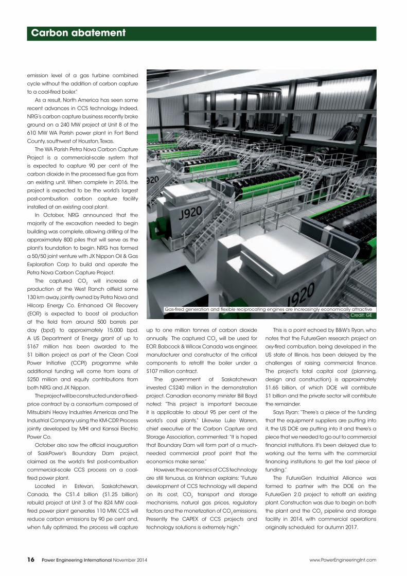
Gas-fred generation and fexible reciprocating engines are increasingly economically attractiveCredit: GE
1411PEI_16 16 11/10/14 9:46 AM
Page 19
Redefine your expectations of anti-corrosion coatings with AvantGuard® by Hempel.eddefifine your expectatiions off a
Hempel introduces AvantGuard®, a new
innovative anti-corrosion technology, based on
activated zinc and locked into our new range of
high performance protective coatings.
AvantGuard® reduces the effects of corrosion
and offers advanced protection. This increased
durability has been proven in extensive tests.
Redefining protection with reduced rust creep
and enhanced corrosion protection
Redefining durability with improved
mechanical strength
Redefining productivity with greater working
tolerances in different climatic conditions and
with high DFT’s. Less repair work needed.
AvantGuard®
Redefining anti-corrosion
For more information:
Email: [email protected]
Visit: www.hempel.com/avantguard
For more information, enter 9 at pei.hotims.com
1411PEI_17 17 11/10/14 9:46 AM
Page 20
18 www.PowerEngineeringInt.comPower Engineering International November 2014
Carbon abatement
As Ryan says: “They’re expensive projects
and you have to build pilot and demonstration
plants to get everyone comfortable that they
can add this technology to their plant.” He
adds: “We’ve been pleased with the DOE
support. They are seeing this to be the future of
coal-fred generation.”
An alliance between commercial and
state parties is also behind Canada’s Canmet
advanced coal-fring research project.
Between 1993 and 1995, CanmetEnergy
invested over C$4 million in building the world’s
frst advanced oxy-fuel combustion pilot-scale
research facility. Since its commissioning in
1995, CanmetENERGY’s CO2 R&D Consortium
is now in Phase 9, which is developing a CO2
capture and compression unit.
Challenging economics
But even with government support, the
economics of CCS can be challenging. For
example, in late September Leucadia National
Corporation announced that it had decided
not to proceed with further development of
the greater Lake Charles project based on
“fnal estimates of the likely ultimate cost”.
The decision came despite a December
2013 announcement from the DOE that it
would support the project to the tune of
$261.4 million under its Industrial Carbon
Capture Sequestration (ICCS) programme.
The petcoke-fred gasifcation plant was to
transport the CO2 to the West Hastings oil feld
for use in EOR. The estimated total cost of the
Lake Charles CCS project was $435.6 million.
The CCS project was to include two Lurgi
Rectisol Acid Gas Removal (AGR) units and
was designed to capture approximately
89 per cent of the CO2 produced.
Nonetheless, there are efforts to further
commercialize CCS technology in the US. In
April SaskPower and Vattenfall signed a fve-
year agreement to explore opportunities
for collaboration on CCS knowledge and
technologies. More recently, Shell Cansolv,
the subsidiary of Royal Dutch Shell behind the
technology used at Boundary Dam, agreed
a deal with Technology Centre Mongstad
(TCM) in Norway for further testing of the CO2
capture process. The testing was scheduled to
start in the third quarter of this year and will last
for approximately fve months.
Given the challenges of developing
economically viable CCS technology – it is
no coincidence that the projects that have
been developed in North America to date are
based at older coal-fred plants and coincide
with opportunities for EOR – the opportunities
for carbon reduction are based on alternative
approaches. As Krishnan explains: “Given the
early-stage development of the affordable
large-scale carbon capture technologies and
associated high CAPEX of transportation and
storage, I believe that the industry will focus on
increasing effciency by innovative equipment
upgrades, best practices and switching to
currently abundant natural gas.”
He continues: “The new EPA carbon
pollution emission guideline for stationary
sources will obviously result in new innovative
approaches outside of CCS to meet the
proposed targets. Power producers will
seriously look at increasing the effciency of
fossil fuel power plants through upgrading
technologies. Switching to coals that will
improve the heat rate of the units and reduce
its utilization will also be employed.”
Krishnan concludes: “In recent years,
marginal or ineffcient coal-fred power plants
have been under tremendous pressure to
lower their cost of generation to improve the
despatchability of their units. As a result, several
innovative boiler effciency improvement
technologies through retrofts, combustion
controls and fuel switching have been
incorporated. These strategies have resulted in
some modest improvement in CO2 emissions.”
Ryan highlights the focus on more effcient
combustion technologies: “About two years
ago we were fortunate to get a contract with
AEP to build the frst [US] ultra-supercritical
unit which is in the just-under-4000 psi steam
pressure range, but the steam temperatures
are up to the 1100–1150 range. That gave a
5 per cent to 6 per cent improvement in heat
rate over the traditional supercritical cycles.”
He adds: “We’re involved in a consortium
of companies here in the US to develop
advanced supercritical technology. That is
pushing the steam pressures up to 5000 psi at
the turbine inlet.”
He points out the challenges of materials
development in achieving these steam
conditions, saying: “The single biggest area
we’re working on now is to make sure we
understand the properties of the material, that
it’s going to withstand those pressures and
temperatures, have the life expectancy that
utilities like to see, and be able to fabricate
and repair the material in the feld. We’re in
the process of designing a small test facility to
actually run some components at the same
steam temperatures. We expect that to be
done next year, and then another year or two
from there we will have the ability to test some
of these components.”
Michael Gradoia, Manager of Power
Generation Product Marketing for GE Power
and Water, also highlights the challenges
of reducing carbon intensity with power
generation products. He says: “Gas turbine
effciency is primarily a function of fring
temperature and compressor pressure
ratio. There is a need for materials that can
withstand those higher temperatures, and
cooling technologies that allow you to reduce
the amount of air used for cooling that is
therefore not used for power.”
For example, GE’s latest products, the HA
gas turbines, utilize single crystal alloys in the
turbine section. Illustrating the challenges,
Gradoia adds: “When looking at a turbine
section, there are components that are
operating at about 400 degrees above
the melting point of the base metals, and
advanced coatings and cooling technologies
are what enable that part to do its job while
providing a reliable service life.”
On improving the effciency of existing
coal-fred assets, Gradoia says: “We can help
enhance the effciency of existing units by
retroftting the steam turbines with the latest
blading and sealing technology.”
Similarly, B&W is looking at developing
technologies and techniques to enable units
to operate more effciently at reduced load.
The US low-carbon future
More than 25 US states have already set energy
effciency targets, and more than 35 have set
renewable energy targets. Meanwhile, it is
evident that the DOE will pursue additional
constraints on carbon.
Ryan says: “In terms of where we think it’s
going at some point down the road, it’s hard
for me to imagine that higher levels of carbon
capture, up to and including 100 per cent,
aren’t going to be required.”
He concludes: “I think it’s a matter of time,
we just have to keep working on development
and getting it to a commercial state.”
David Appleyard is a freelance journalist
focused on the energy, technology and
process sectors.
Visit www.PowerEngineeringInt.com for more information i
1411PEI_18 18 11/10/14 9:47 AM
Page 21
YOU AIN’T SEEN
NOTHING YETThe new benchmark in electric valve actuators
All will be revealed
Valve World Expo D¸sseldorf December 2nd ñ 4th, 2014
Hall 3 Booth D36
[email protected] , www.siposseven.com
STAY AHEAD. STAY SIPOS
P R O F I T R O N
For more information, enter 10 at pei.hotims.com
1411PEI_19 19 11/10/14 9:47 AM
Page 22
Right from the initial selection of
a drive, a designer has to make
careful considerations when
looking for the optimal motor for
their application. Determining
the torque and speed, selecting
a pneumatic motor from suppliers’ catalogues
and clarifying the size and connections
required for the machine – it sounds simple.
But unfortunately it is not that easy, and a rude
awakening may follow if, after installation, the
selected pneumatic motor does not produce
the power required. Determining the problem
may take weeks; in the worst-case scenario the
entire drive may have to be redesigned and
purchased again. Therefore it is worthwhile to
talk to the specialists at the beginning of the
drive design phase.
Deprag Schulz has developed a simple
guide with six steps to follow so that nothing
is forgotten.
The selection of a pneumatic motor is
not diffcult. But, particularly with pneumatic
systems, there are many factors which can
decisively infuence the power of an air motor.
If, for example, when installing a motor it is
found that too short a hose has been chosen,
then this will drastically reduce the torque of
the motor.
You can imagine that the developer does
not necessarily have the length of hoses at
the forefront of their mind when designing the
machine; equally; the connectors between
the flter units and oiler are not considered to
be particularly relevant. But it is exactly these
throttle points which ultimately determine
whether the machine works correctly and if
the motor provides the right torque.
Steps to selecting the right motor
So what are these steps for the selection of
the right motor? First of all, the drive system
best suited to the customer’s application must
be chosen. Then the materials of which the
external parts of the motor are composed are
determined. After these initial decisions, the
theoretically required motor power can be
calculated and all performance-infuencing
factors can be taken into consideration.
The fourth step is the integration of the
motor into the complete system of the
machine. You have to decide how the motor
will be connected to the machine and
which gears are required. Perhaps a brake
Motors and drives
Selecting a drive involves careful consideration when looking for the optimal motor for a given application. Dagmar Dübbelde looks at how to avoid design errors and save money
An engineer’s guide to selecting a drive
For use in potentially explosive environments, ATEX certifcation is an option
Credit: Deprag Schulz
20 Power Engineering International November 2014 www.PowerEngineeringInt.com
1411PEI_20 20 11/10/14 9:47 AM
Page 23
Through the Alternative Energy Source Incentives
Program (Programa de Incentivo ‡s Fontes
Alternativas ñ PROINFA), a total of
41wind power projects have been put into
action, spurring the still nascent industryís
development throughout Brazil.
Because of the program, another,
19 biomass thermal stations, powered
by rice husks and sugarcane bagasse, are in
operation with the support of ELETROBRAS.
ELETROBRAS is committed to generating clean and renewable energy. The majority of the energy
produced by the company derives from these sources.
Cutting-edge projects such as Megawatt
Solar, implemented in Brazilís South Region,
and Xapuri, in the state of Acre, employ solar
photovoltaic panel technology.
ELETROBRAS is one of the leading producers of electric energy in Brazil. In this light, it is encouraging
to know that a substantial portion of this energy stems from clean and renewable sources. In
addition to tapping hydroelectric power, one of the cleanest known sources of energy, ELETROBRAS
��������������������������������������������������� ���������������������������������������������
Brazilís energy sources and leveraging the related industries. These initiatives have helped transform
the Brazilian energy grid into one of the industrialized worldís most renewable systems.
It is for these reasons that ELETROBRASís work stretches as far and wide as Brazil itself.
eletrobras.com
Ministry ofMines and Energy
B R A Z I L I A N G O V E R N M E N T
For more information, enter 11 at pei.hotims.com
1411PEI_21 21 11/10/14 9:47 AM
Page 24
22 www.PowerEngineeringInt.comPower Engineering International November 2014
Motors and drives
will be necessary in order to ensure safety
of the system. Then the durability of the
machine must be guaranteed, and fnally the
purchasing and running costs of the motor
must be calculated and optimized.
Pneumatic motors are available in
diverse design options. Their application and
the intended operating time are of great
importance when selecting the right basic
principles. An air vane motor is suitable for
regular running cycles. If you wish to run it non-
stop then you must consider the wear on the
vanes and the shorter maintenance intervals
this requires. In comparison, gear motors and
turbines are maintenance-free and therefore
better suited to continuous operation. In this
case the required speed must be considered.
Turbines and gear motors rotate in upper
speed ranges at approximately 140,000 rpm.
Vane motors are available which rotate at
very low speeds, e.g., 1 rpm. Oil-free operation
is also an option for all three drive principles. A
slight loss of power must be taken into account
with oil-free operation of a vane motor.
Different materials
The second step examines the motor’s
construction material. If operating in a dry
surrounding atmosphere and in normal
stationary production, an inexpensive air
motor made from cast iron will be suffcient.
Deprag offers a wide spectrum of low-priced
Basic Line motors. For installation in robots
and machines there are a variety of grinding
motors, drilling motors and milling motors
available which are distinguished by their low
weight and compact size.
For use in the food industry, pneumatic
motors must be able to withstand cleaning
agents and steam. The Deprag Advanced Line
motors with external parts made from stainless
steel are additionally sealed and lubricated
with food industry standard USDA-H1 grease.
Pneumatic drives can even be operated
underwater. In this case it is essential to
determine the water depth required. If the
motors must be started underwater they
can be used up to a depth of 5 metres. If
the motors are started on the surface and
then submerged, they can be used in a
depth of up to 20 metres without damaging
the motor. If the motor must be sterilizable,
as requirements demand in some medical
technology applications, then it can be
equipped with special vanes. There are many
examples here of why it is important to speak
to the air motor manufacturers in advance
about your application and to describe it in
as much detail as possible.
Motor power
The next step is the calculation of the
theoretical motor power. Motors which are
designed for use in only one rotational
direction are more effcient than reversible
motors. When determining the rotational
direction, the pneumatic expert looks towards
the motor shaft from the air inlet. This is the
other way around for electric motors, where
the rotational direction is specifed by looking
at the motor spindle.
First the required working point of the motor
is determined: which nominal torque and
speed under load do you want to reach? The
most economic use of the motor (least wear
and least air consumption) is attained by
running close to the nominal speed. If you look
at the characteristic curve of an air motor, it
shows that it reaches its maximum torque just
before standstill (around twice the specifed
nominal torque).
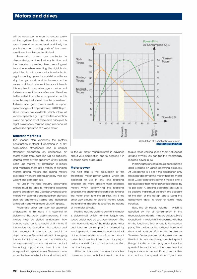
At the nominal speed the air motor reaches
maximum power. With the formula nominal
torque times working speed (nominal speed)
divided by 9550 you can fnd the theoretically
required power in kW.
In manufacturers’ catalogues, performance
data is based on varied operating pressures.
At Deprag this is 6 bar. If the application only
has 5 bar directly at the motor then the motor
loses 23 per cent of its power. If there is only 4
bar available then motor power is reduced by
45 per cent. A differing operating pressure is
so decisive that it must be taken into account
at the start of the design phase using the
adjustment table, in order to avoid nasty
surprises.
Next, the air supply volume – which is
specifed by the air consumption in the
manufacturers’ details – must be ensured. Every
reduction in the width of the opening, whether
on the feed hose itself or due to connection
parts, flters, oilers or the exhaust hose and
silencer all have an effect on the air volume.
Therefore Deprag recommends an exhaust air
throttle to its customers to regulate their speed.
Using a throttle on the supply air reduces the
speed of the motor but, at the same time, the
torque is reduced as well. Exhaust air throttles
can reduce the speed without great loss
Calculation of theoretical motor power
Credit: Deprag Schulz
1411PEI_22 22 11/10/14 9:47 AM
Page 25
www.PowerEngineeringInt.com 23Power Engineering International November 2014
Motors and drives
of torque. The exhaust throttle means that
customers can better utilize the wider working
range which air motors provide.
The optimal lifespan and performance of
an air motor is reached with lubricated running
(1–2 drops of oil per 1 m³ air consumption).
Unlubricated operation can lead to a loss of
power of around 10–20 per cent.
Design integration
If the right motor with the required power has
been found, then the next step is to integrate
it into the design. Deprag provides various
spindle designs and individual fxing methods.
A complete solution is often better value
than seeking a gear solution separately.
Within the Deprag range there are numerous
air motors with integrated planetary gears,
spur gears and worms gears. If you require
additional safety then a holding brake can
be recommended. In the manufacturer’s
programme you can also fnd brake motors.
For use in potentially explosive environments,
there are also options with the required ATEX
certifcation. Integration is concluded with
the technical verifcation of the maximum
permissible axial and radial load on the drive
spindle of the air motor.
Air motors are powerful, durable and
robust. Adherence to the framework
conditions determined during the design
phase and compliance with the instruction
manual will ensure the longest possible life of
the drive. These conditions include adhering
to the recommended air quality, lubricated
operation, maintenance intervals, a maximum
length of the feed hose of three metres and
suffcient opening widths of the feed hose and
connection parts.
Considering costs
Finally, the purchase price is the predominant
consideration in the acquisition of a new
drive system. But the designer should also
remember running expenses and consider the
operating costs and price for maintenance
and servicing. When planning and selecting
a new system, the question must be asked:
how readily available are replacement parts
and what are their prices? Maintenance and
repair service quotations ensure that this is
calculable. Deprag’s Basic Line air motors
are particularly maintenance-friendly. The
patented vane exchange system enables
an air motor’s vanes to be quickly replaced
in situ using a key and tweezers. Operating
costs are determined by the air consumption.
The right choice of motor sets the course for
low running costs. The closer the motor runs to
nominal speed (50 per cent of the idle speed),
the more effciently the air is used.
Deprag Schulz has been using compressed
air as a working medium for many decades.
Deprag’s standard programme offers a wide
range of options and, from this modular
system, individual drive solutions for the
required application can be developed and
produced at an attractive price-performance
ratio. Around 85 per cent of the frm’s projects
in the feld of air motors are special solutions
which have been quickly and simply realized
from its standard programme.
Dagmar Dübbelde is Product Manager, Air
Motors at Deprag Schulz
Visit www.PowerEngineeringInt.com for more informationi
ONLY ONEBOLTING SYSTEM
IMPROVESSAFETY, QUALITY,
& SCHEDULEFOR GAS TURBINE
MAINTENANCE
1411PEI_23 23 11/10/14 9:47 AM
Page 26
Risks of unwanted combustion
– potentially causing injury,
damage and/or downtime
– occur everywhere coal is
handled, processed or stored.
Safe coal handling practices
are designed to ensure that the fuel remains
intact throughout its journey from the mine
until the point at which it is ignited in the boiler.
It takes as little as 1.4 kg of pulverized
coal in 28.3 m3 of air to form an explosive
mixture. Since a large boiler burns 45.4 kg or
more of coal per second, the safe burning of
pulverized coal necessitates strict adherence
to planned operating sequences.
All coals oxidize during storage, but sub-
bituminous coals are especially prone to self-
ignition. The increasing use of sub-bituminous
coals throughout Asia has increased the risks
of silo fres.
Good operating procedures are designed
to ensure that coal is used before it has time to
self-ignite, and many operators use a nitrogen
blanket to minimize the scope for oxidation.
Even with appropriate precautions, silo fres
can still occur and appropriate monitoring is
needed to prevent oxidation from developing
into a silo fre.
The greatest risk of fre occurs when the
mill is shut down under load, as this leaves a
large amount of pulverized fuel inside a hot
mill. The large surface area of the pulverized
coal and the high temperature inside the mill
lead to rapid oxidation of the coal. This results
in further heat buildup and the potential for a
fre. If the mill is restarted without frst removing
the hot coal, an explosion can occur when
particles are suspended and exposed to
the air.
Even in routine mill shutdowns, there is a
danger that any residual coal left within the
mill will oxidize, and may explode as the mill
is restarted. To prevent a coal fre, the mills can
be made inert with a steam deluge when an
unexpected shutdown occurs, or when there
is a high risk of a coal fre.
Several methods are available to detect
the presence of oxidization within the mill or
silo:
lThermocouples are widely used to detect
the heat buildup from oxidation or an early-
stage mill fre, but they have limited sensitivity
and discrete sensors have diffculty
monitoring the whole volume of the mill. It
also takes time for suffcient heat to build up
within the mill to give a detectable increase
in temperature. Experience shows that
thermocouples do not provide a reliable
indication that a hazardous condition is
developing.
Coal plant safety
Equipment selection and operating criteria are vital for reducing the risk of fre in coal storage silos and mills, writes Derek Stuart of Ametek
Strengthening safety in mills and silos
Hoosier Energy’s Merom Generating Station in Indiana, US
Credit: Ametek Land
24 Power Engineering International November 2014 www.PowerEngineeringInt.com
1411PEI_24 24 11/10/14 9:47 AM
Page 27
The single-phase enclosed HB3-80 generator
switchgear provides for sustainable and reliable power
supply in power plant technology.
The HB3-80 is the first generator switchgear worldwide
with vacuum generator circuit-breakers for ratings up to
10,000 A with natural cooling, and a switching capacity of
80 kA type-tested according to the IEEEC37.013 standard.
Thanks to its single-phase enclosure if offers maximum
operational and personal safety, as short circuits between
phases are excluded.
www.siemens.com/generatorswitchgear
Totally Integrated Power
Applications:
Power plant generating units up to 160 MW or 250 MW,
depending on the on the type of power plant and
operating voltage
Indoor and outdoor installation
Advantages:
Optimum operational and personal safety
Sustainable and environmentally friendly
vacuum technology
Minimum installation and maintenance costs
High cost-efficiency and service continuity
HB3-80 generator switchgearTrend-setting with vacuum technology
IC1
00
0-E
32
0-F
23
6-X
-76
00
For more information, enter 12 at pei.hotims.com
1411PEI_25 25 11/10/14 9:47 AM
Page 28
26 www.PowerEngineeringInt.comPower Engineering International November 2014
Coal plant safety
lCarbon monoxide (CO) gas detection offers
a fast and sensitive means to detect the
presence of oxidizing coal, as the oxidation
inevitably produces large amounts of CO.
The most important reasons to choose CO
measurement for this application are the
availability of sensitive CO sensors able
to detect a few parts per million (ppm)
of CO, and the ability to sample a large
portion of the mill using a probe mounted
at the classifer outlet. CO monitoring is fast,
sensitive, specifc and can be calibrated to
determine alarm levels that reliably identify
a potentially hazardous condition while
minimizing the occurrence of false alarms.
•Once a fre has started, optical detectors
respond to sparks and fames within the mill.
By the time fames are visible, it is too late to
take preventative actions because the mill is
already in a very hazardous condition.
One of the biggest challenges in
confguring a Millwatch system is the
determination of suitable alarm levels. A
carbon monoxide concentration greater than
250 ppm can be seen during mill startup, but
in normal operation the CO concentration is
in the region of 10 ppm.
Millwatch analyzers offer two independent
alarm points, so alarm levels were set at
300 ppm during startup and 50 ppm in
normal operation. Although the startup alarm
seemed robust, there were occasional spikes
above 50 ppm CO in normal operation, so the
alarm level was increased several times with a
fnal fgure of 125 ppm. This avoided nuisance
alarms, while providing good sensitivity and
response to abnormal operating condition
when the mill may need to be inerted.
Monitoring in China and the US
HouShiPower is a 4200 MW electricity
generating plant in China’s Fujian province,
operated by the Huayang Group. It supplies
electricity to the city of ZhangZhou and the
surrounding area.
There are seven electricity generating
units at the site, each of which is rated for
600 MW. In 2011, the plant operators decided
to add CO monitors to the fve coal mills in Unit
1, supplementing their existing temperature
and fre sensors. They determined that
Ametek Land’s Millwatch analyzers were best
suited to the task. The analyzers have a long
track record, with hundreds of installations
worldwide, and include a number of desirable
features:
lRugged sample probes with automatic
blowback to maintain a good sample fow;
lAutomatic calibration verifes correct
operation of the analyzers, confrming that
they respond correctly to CO;
lContinuous measurement of each sample
point, with no multiplexing and response
time less than 60 seconds.
This last feature is especially important as a
hazardous condition can develop within a few
minutes, and a multiplexed system sampling
six measurement points will typically sample
each point only once every 10–15 minutes.
The system proved its value in 2013 when
the Millwatch system showed rapidly rising CO
levels in the outlet of one of the coal mills. It
would have taken at least 15 minutes for the
temperature and fre detection systems to
respond and show an indication of a problem,
so the Millwatch analyzers allowed corrective
action to be taken signifcantly earlier than
would otherwise have been possible.
Hoosier Energy’s Merom Generating Station
in Indiana, US, is a coal-fred baseload plant
with two 535 MW generating units. It went into
commercial operation in 1982 and provides
power to electric distribution co-operatives
in the midwestern US. At full load it uses
10,000 tonnes of coal per day, with the supply
coming from mines by road and rail.
Hoosier Energy has a strong commitment
to safety and maintains a robust safety
programme, endeavouring to operate with
the utmost regard for the health and safety of
its employees and the public.
Each generating unit at Merom Station
has three Riley Power double-ended ball tube
mills. The mills can each provide 65 tonnes per
hour of pulverized coal to the boiler, a total of
195 tonnes per hour per boiler. The boilers at
Merom station burn 54 kg of coal per second.
Because the ball-tube mills have outlets
at each end with a classifer on each outlet,
two sample points were needed on each
mill. For enhanced reliability, a redundant
confguration was chosen with two sample
points on each classifer, giving four samples
per mill. With three mills per generating unit,
a total of 12 sample points were needed
for each unit or six twin-stream analyzers.
Redundant measurements reduce the
likelihood of a nuisance alarm, as a high CO
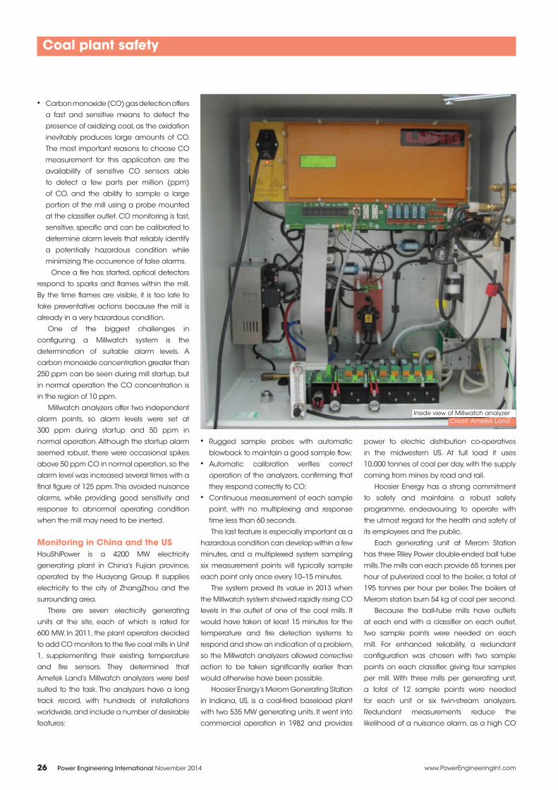
Inside view of Millwatch analyzer
Credit: Ametek Land
1411PEI_26 26 11/10/14 9:47 AM
Page 29
www.PowerEngineeringInt.com 27Power Engineering International November 2014
Coal plant safety
measurement is unlikely to be detected on
one coal pipe while the others continue to
show normal readings.
The initial proposal was to mount the
sample probes directly on the classifers.
Even though the inside of the classifer is
a hazardous area, the sample probes are
simple devices with no electrical connection
and so no special precautions were needed.
Although this would have provided a
representative sample, the probes have an
abrasion shield which prevents the stainless
steel flter from being damaged by the high
concentration of coal dust. An installation
location at the classifer outlet was preferred,
since this allowed the abrasion shield to face
the fow of coal dust and protect the flter.
Blowback controllers were installed close
to the classifers, but outside the hazardous
area.
Along with the CO monitors, an in situ
oxygen probe was installed on each classifer,
to determine the oxygen concentration while
the mills are steam-inerted. The CO analyzers
were installed at the same level as the
classifers. This meant that the sample lines
could be kept short and the response time
minimized. The chosen location also gave
easy access for maintenance. Commissioning
took place during an outage in May 2011.
In the three years since the Millwatch
analyzers were installed at Merom Station,
there have been a number of high-CO
alarms, but no mill explosions -- an impressive
achievement for a baseload station. During
that time, the Millwatch analyzers have proven
to be reliable, requiring no more than routine
maintenance and providing enhanced
safety.
On 8 December 2013, the Millwatch
analyzers demonstrated their value. With Unit
2 running at full load, one of the mills tripped
and the operators observed a rapid increase
in CO readings even though there was no
indication of a temperature rise. Within a few
minutes, the CO level was above the alarm
threshold, and the operators made the
decision to activate the deluge system. The
boiler continued to operate using coal from
the remaining mills, with output dropping to
60 per cent of its rated value.
The CO level in the affected mill started
dropping after 15 minutes, and within
45 minutes it was below 10 ppm. The mill
was restarted two hours after the high CO
alarm was detected, and was returned to full
operation in three and a half hours.
The Millwatch CO analyzers detected a
potentially dangerous condition and allowed
it to be dealt with quickly with no damage to
plant or personnel.
In conclusion, CO monitoring provides a
rapid and reliable method for detection of
potentially dangerous coal oxidation within a
mill so that action can be taken to reduce the
risk of a fre or explosion.
At both HouShiPower Plant and Hoosier
Energy Merom Station, Millwatch analyzers
from Ametek Land have provided good
reliability and a high level of safety coverage
with no explosions in the mill since they were
installed more than three years ago.
Derek Stuart is Product Manager at Ametek
Land, based in Pittsburgh, Pennsylvania, US
Visit www.PowerEngineeringInt.com
for more information i
Customized special control valves
For the energy producing and consuming industry
WELLAND & TUXHORN AG
A R M A T U R E N - U N D M A S C H I N E N F A B R I K
Gütersloher Straße 257 | D-33649 Bielefeld | Tel. +49 (0)521 9418-0 | Fax. +49 (0)521 9418-170, -156 | www.welland-tuxhorn.de | [email protected]
• HP-, IP- and LP-
turbine–bypass–systems
• turbine emergency stop valves
• turbine control valves
• steam conditioning valves
• feedwater control valves
• minimum flow control valves
• cooling water injection valves
• boiler start up valves
• boiler blow down valves
• desuperheater valves
• hydraulic actuating systems
THE AMERICAN SOCIETY
OF MECHANICAL ENGINEERS
For more information, enter 13 at pei.hotims.com
1411PEI_27 27 11/10/14 9:47 AM
Page 30
Combustible materials,
dust and debris, and
voluminous areas make
fre detection for power
stations challenging.
Solutions must be
sensitive to danger and raise alerts early, but
must not be prone to costly false alarms. This
all amounts to another serious problem the
power station safety offcer or facility manager
has to face.
In July of this year, the UK’s Ferrybridge
power plant was affected by a fre widely
reported in the media.When the nationally-
broadcast images had begun to fade from
memory, the cost to Ferrybridge’s owner, SSE,
began to be calculated.
RBC Capital analysts estimated
a loss in earnings of around
£35 million ($56 million). SSE will also have
to factor in the cost of repairing the facilities
(although insurance will cover much of the
losses) and the transactional costs of buying
back forward-contracted power that will now
need to be sourced from elsewhere.
Just weeks ago Didcot B Power Station, also
in the UK, suffered a major fre in its cooling
towers. More than 25 fre appliances from
as far as 30 miles away were called to the
1360 MW gas-fred plant, which is operated by
RWE npower.
While the full costs of the damage are
still being calculated, the impact on the UK’s
power needs has generated much debate.
Peter Atherton, energy analyst at Liberum
Capital, stated that the risk of blackouts this
winter was now far higher due to the UK’s
“meagre capacity” to absorb unexpected
events.
As developed countries fnd power
disruption an unacceptable situation, the
extra capacity in the system should see the
UK with the energy supply it needs over winter,
providing that other major fres and incidents
to power generation are avoided. But for a
single power plant to make the possibility
of power shortages a reality shows the
importance of protecting these critical assets.
The challenges
The sheer size of power plants makes fre
detection a challenge: the huge ground
area occupied, the ceilings often as high as
20 metres and the voluminous areas that must
be monitored.
This presents diffculties in terms of the time
it takes for smoke to reach detectors – and it
may not reach them at all owing to smoke
stratifcation. We can also factor in the need to
provide a system that can cover large areas
effectively – no easy task.
Turbines also present a very industry-
specifc issue: fre is initially hard to detect as
the shell can obscure and contain fames for
some time, impeding early detection.
Power generation environments are known
for their high levels of dirt, grease, dust and oil.
This, of course, means that any fre detection
system needs regular maintenance.
Moreover, the combustible nature of oil,
gas, coal and renewable waste makes plants
vulnerable, and with the debris that can be
kicked up there is the inherent danger of
numerous false alarms. A balance needs to
be struck between the required sensitivity and
false alarms, which some fre services are now
demanding visual verifcation for commercial
properties before attending, while some levy
fnes for being called out for false alarms.
If suppressants are released, then for
voluminous areas the cost can be substantial,
certainly well in excess of £100,000 for many
sites. The attendant environmental impact
such as wash-off running into water supplies
also needs to be considered.
Fire detection technology
Visual Smoke Detection (VSD), Infra-red (IR)
and Aspirating Smoke Detectors (ASD) are the
principal options for power station operators.
Each has advantages and drawbacks.
VSD uses motion system technology to
identify and analyse the behaviour of smoke
patterns and fames Visual monitoring at the
point of fre danger is particularly suited to
large areas and across distances.
Fire detection
As the UK suffers the second major blaze at a power plant in three months, Ali Aleali of FireVu explains the fre detection challenges and solutions
facing power plant operators
Hot topic
The effort involved in fre detection is justifed by the need to protect valuable power assetsCredit: Dreamstime
28 Power Engineering International November 2014 www.PowerEngineeringInt.com
1411PEI_28 28 11/10/14 9:47 AM
Page 31
www.PowerEngineeringInt.com 29Power Engineering International November 2014
Fire detection
Footage can offer visual verifcation (usually done on-site) and
large area monitoring, and can direct the use of fre suppressants and
emergency services.
Temperature sensing capabilities can be incorporated within the
system, the latter being a new innovation in the market.
Infrared converts radiant energy in the IR into a measurable form.
Detecting IR energy emitted by objects takes away reliance on visible
light, so obscured conditions should not affect its effectiveness although
thick smoke is an issue. Oil and grease can also be problematic.
IR gives much of the VSD solution, however the latter offers
accompanying video, which provides better situational awareness in
the event of a fre. It also helps determine the most appropriate action
that should be taken, triggering an overall suppression system.
ASD is a highly sensitive technology. It can detect smoke before it
is visible to the human eye, which is particularly valuable where a fre
develops in obscured or diffcult-to-access locations or environments
containing dangerous and toxic substances. Yet the sensitivity to
distinguish between smoke and dust in early-stage fres can be
problematic in some facilities, although improvements are being
introduced. Moreover, it requires that smoke hits detectors, which can
be challenging if smoke stratifcation is a possibility.
Ferrybridge and now Didcot remind us of the costs of fre in power
generation environments. Safety professionals must analyse their
requirements against the solutions available, be it VSD, ASD, IR or another
system. Fire detection for power stations requires planning, frequent
maintenance and continual assessment, but the effort is justifed by the
need to protect these high-value assets.
Ali Aleali is Business Development Manager at FireVu, which
works with power plants across the UK and Ireland. Please visit
www.frevu.co.uk
Visit www.PowerEngineeringInt.com for more informationi
VSD operator’s dashboard: Users can segment the video to concentrate on
specifc areas of greater fre risk
Credit: FireVu
HIGH PERFORMANCE
Electric actuators for the
power plant industry
Reliable, powerful, precise control. AUMA
offer a large portfolio of actuator and
gearbox type ranges.
■ Automating all types of
industrial valves
■ Standardised interface for
various site control systems
■ Plant Asset Management functions
■ Service
worldwide
Discover
our solutions
for the
power plant
industry
www.auma.com
For more information, enter 14 at pei.hotims.com
1411PEI_29 29 11/10/14 9:47 AM
Page 32
Since the 1920s, steam generator
owners have used particulate
removal technologies such as
cyclones, fabric flters, or dry or
wet electrostatic precipitators
(ESPs) to collect fue gas particles
such as fy ash.
Today utilities expect ESPs to effciently
remove very fne particulates (e.g., PM10) and
often rely on a wet fue gas desulphurization
(FGD) system to remove smaller and harder-to-
capture sub-micron particulates (e.g., PM2.5,
mercury, and other hazardous emissions)
as a co-beneft. Experience has shown that
problems often occur when a FGD system is
added without a concurrent ESP performance
upgrade.
ESP operation, in principle, is very
straightforward. Particles to be removed from
the gas stream are charged by a series of
high-voltage electric discharge electrodes
to produce negatively charged ions (corona
discharge) that charge the particles in the
fue gas, providing the driving force for moving
particles to the collecting plates.
Next, plates stationed parallel and on each
side of the gas stream are grounded in order
to attract and accumulate the negatively
charged particles in cake-like layers on the
plate surface. Finally, the particulate matter
is removed from the plates by mechanical
rappers causing the material to fall into
collection hoppers from which it is disposed
or recycled. The ESP removal effciency is
highly dependent on the voltage differential
between the discharge electrode (Eo) and the
collection plate (Ep). The typical ESP operates
at a voltage in the range of 30 kV and 100 kV.
The typical ESP will have multiple discharge
electrodes between each set of collecting
plates and multiple sets of collecting plates in
a single ‘feld’ in the direction of gas fow. Each
feld acts as an independent precipitator.
Multiple felds may be added in series to
improve particle removal effciency with most
plants using three or more felds.
Retroftting
Poor electrostatic precipitator performance can often be traced to an underperforming high voltage power supply. Retroftting with a high frequency switch mode power supply can quickly reduce particulate emissions and often improve the performance of a downstream wet fue gas desulphurization system, writes Jason Horn
Fly ash has been collected by particulate removal technologies since the 1920s
Credit: Pittsburgh Mineral & Environmental Technology
30 Power Engineering International November 2014 www.PowerEngineeringInt.com
A fresh perceptionof ESP
1411PEI_30 30 11/10/14 9:48 AM
Page 33
www.PowerEngineeringInt.com 31Power Engineering International November 2014
Retroftting
Some plants use up to 12 felds in order to achieve collection
effciencies greater than 99 per cent. In most utility applications, each feld
is also electrically divided into separate compartments or ‘lanes’ to further
optimize particulate removal effciency, primarily due to temperature
and fow rate gradients across the fue gas entering the ESP. The ESP has
been chosen as the PM removal device in over 90 per cent of utility
applications due to its low pressure drop (usually 0.5–1.0 inch water
column), which translates into less auxiliary fan power.
The particle removal effectiveness of an ESP is largely based upon
the resistivity of the particles (the ability of a particle to hold a charge),
the gas fow properties, and the quality and strength of the electric feld
produced between the electrodes and collection plates. Also, a fuel
change often changes the resistivity of the particles in the fue gas.
The recent US Mercury and Air Toxics Standards (MATS) also place
limits on mercury and acid gas limits on boilers that may require adding
activated carbon injection for mercury removal and/or dry sorbent
injection to remove acid gases. Adding activated carbon or dry sorbent
to the gas stream may change the particle resistivity and therefore
the effciency of ESP operation. Other changes in the fue gas, such
as volumetric fow rate, moisture content, chemical composition, and
temperature can also adversely impact the particle collection effciency
of an ESP.
There are a number of upgrade alternatives available to those
needing to increase the particulate removal capacity or those
experiencing an underperforming ESP. Options available to the end
user are increase collecting surface area, improving the fow distribution
entering the ESP, and upgrading or replacing the collection plates or
discharge electrodes. Each of these options requires extensive physical
changes to each stage of the ESP and all require an extended unit
outage and signifcant cost.
The conventional power supply system for an ESP consists of the
transformer-rectifer (TR) set current-limiting reactor (CLR), and silicone
controlled rectifer (SCR) that produce the high voltage power source
for the discharge electrodes. The TR set is a high voltage transformer and
rectifer that converts single phase AC power to single-phase DC power
with approximately 30 per cent ripple in the output voltage waveform
due to 50/60 Hz operating frequency.
The CLR provides current limiting during transient overload (sparking)
conditions. The SCR regulates the voltage into the TR set to adjust the
output voltage and current to the ESP. Separate conventional power
systems are used on each ESP stage (sometimes each lane in a feld) in
order to optimize individual feld performance.
Anatomy of the switch mode power supply
Often a quicker, less intrusive and more cost-effective solution to improve
ESP performance is replacing the conventional power supply system
with a high frequency switch mode power supply (SMPS) that converts
50/60-Hz power to low ripple DC with output waveform ripple below 3
per cent.
The reduced ripple in the output voltage allows the SMPS
to produce a higher average output voltage (Eo), which in
turn produces higher collection effciency. The typical voltage
output from the SMPS – usually determined by ESP plate spacing,
discharge electrode type and particle resistivity – ranges from
50 kV to 120 kV with improved spark handling. The SMPS also has a faster
spark and arc response time – microseconds instead of milliseconds
FROMENGINEERINGANALYSIS TO ADVANCED NDE,LOOK TOSTRUCTURAL INTEGRITY
( 8 7 7 - 4 S I - P O W E R )8 7 7 - 4 7 4 - 7 6 9 3
Scan the QR Code for more information
www.structint.com/power-eng-int
We Connect the DotsOver the past 30 years, Structural Integrity has built a team of over
200 industry experts providing comprehensive solutions to the energy industry. We connect the dots from problem to resolution, from regulations to compliance, from nondestructive examination, to engineered solutions, even custom equipment.
You can look to us for our:• Knowledge of power plants, codes, and how
things work.• Extensive experience and leadership.• High quality, hard work, and responsiveness.
Call us today and we’ll connect the dots for you.
For more information, enter 15 at pei.hotims.com
1411PEI_31 31 11/10/14 9:48 AM
Page 34
32 www.PowerEngineeringInt.comPower Engineering International November 2014
Retroftting
– that reduces power dissipated in sparks
and arcs and reduces wear on power feed
components and ESP internals.
The SMPS upgrade option has two principal
benefts that are dependent on how the unit
is operated. The frst beneft is to improve ESP
collection effciency when less particulate
emissions are desired. The SMPS puts more
power (increased Eo) into the ESP resulting in
higher collection effciency.
The second beneft for plant owners is for
a unit where less ESP auxiliary power use is
desired in order to either improve unit heat
rate or increase sellable power to the grid. With
this option, the SMPS replaces the ineffcient
conventional power systems used on an
ESP operating with acceptable collection
effciency by limiting the power output to
that of the TR and CLR it replaces. The SMPS
operates at >90 per cent power effciency
compared to the TR, which generally operates
at <60 per cent. For the same power input
into the ESP (and the same ESP collection
effciency), SMPS can reduce auxiliary power
use by 30 per cent.
ModuPower SMPS systems have also been
used in a variety of unique applications, as the
following three case studies will illustrate.
Case studies
For example, at AES Gener’s 135 MW coal-fred
Norgener Power Station, located in Tocopilla,
Chile, its 1990s vintage ESP met air emissions
standards when built. New regulations that
went into effect this year reduced the level
of permitted particulates from 211 mg/Nm3
(98 per cent removal rate) to 50 mg/Nm3
(99.95 per cent removal rate). The reduced
emissions limits would require a unit derate in
order to continue operating.
Norgener replaced three of the four
conventional power supply systems on
each unit with Stock Equipment Company’s
ModuPower SMPS, which allowed Norgener to
increase generation to full load on each unit
while maintaining particulate emissions below
the new particulate discharge limits.
A 640 MW supercritical utility boiler located
in Ohio was reconfgured with a wet FGD
downstream of its existing four-lane/12-feld
ESP. It was assumed during design that the
new wet FGD would capture particulates not
removed by the ESP, so no enhancements to
the ESP were made as part of the FGD retroft
project (see Figure 1).
However, shortly after the FGD was
commissioned, the plant determined that
excessive particulates were entering the FGD
and fouling pumps, pump linings, and piping.
Also, the ash contamination reduced the
quality of the gypsum byproduct from the
FGD, negating its market value. Instead of a
positive cash fow from the sale of the gypsum,
the utility must pay the cost of landflling the
waste product.
During the frst year, authorities allowed
the plant to ‘bypass’ the FGD system when
it required monthly maintenance to repair
damage caused by excess particulate
emissions from the ESP.
However, after the frst year of operation a
monthly unit outage was required to perform
FGD maintenance, an untenable situation for
a baseload unit. The site was limited in size so
adding felds to the ESP wasn’t an option.
Stock Equipment Company was asked
to evaluate options for repowering the ESP in
order to reduce particulate emissions entering
the wet FGD.
The solution was to add four
ModuPower SMPS systems of 60 kW
(83 kV/1080 mA) for each lane in the second
and third felds and four 90 kW (83 kV/
1080 mA) systems for each lane in the sixth
feld. This approach allowed the original inlet
feld TR sets to perform the relatively easy chore
of removing large, friendly particles in the
front of the ESP, and to use ModuPower SMPS
systems to do more diffcult removal work in
the center of the ESP.
The ESP represented a special challenge
in that access to its roof was diffcult, and
there was little space available in which to
locate the ModuPower SMPS equipment.
Also, another SMPS brand previously installed
had failed to operate reliably in the high
temperature and dirty environment within the
ESP weather enclosure.
With this in mind, Stock Equipment worked
with the customer to remote-mount the
ModuPower units in a pre-wired modular
control room that was located on the ground
at the base of the ESP. The entire system was
delivered as two structures, each containing
six of the 12 ModuPower units provided. The
plant was required to only connect power to
the switchgear provided in each control room
and run high voltage cable to the roof of
the ESP.
All the installation work was completed with
the unit in operation, with only a short outage
required to make the fnal electrical tie-in to
the ESP. This unique remote SMPS installation
provided by Stock Equipment enhanced the
project’s ROI signifcantly.
The ModuPower SMPS installation
produced an over 100% increase in power
sent to the ESP, from 464 kW to 1052 kW. With
the exception of the inlet felds that are
exposed to the highest dust burden, all felds
are operating at the nameplate current limit
rating of both the ModuPower units and the
original TR sets.
More importantly, the repowered ESP has
eliminated outages caused by excessive
particulates entering the FGD and restored
the quality of the gypsum by-product. The
plant has since installed an additional 12
Figure 1: Ohio plant ESP roof with ModuPower ground switches installed on the insulator compartment
Credit: Stock Equipment Company
1411PEI_32 32 11/10/14 9:48 AM
Page 35
For more information, enter 16 at pei.hotims.com
1411PEI_33 33 11/10/14 9:48 AM
Page 36
34 www.PowerEngineeringInt.comPower Engineering International November 2014
Retroftting
ModuPower SMPS systems on felds 1, 4, and 6
of the same unit.
A 670 MW supercritical utility boiler located
in West Virginia, US is confgured with a wet
FGD after its ESP (see Figure 2). The ESP is
confgured as four felds deep, eight lanes
wide, with each feld using weighted wires on
a nine-inch gas passage spacing. Though the
ESP as designed did not perform effectively,
it did not experience excess particulate
emissions because of the downstream wet
FGD. However, the two induced draft (ID) fans
that are positioned between the ESP outlet
and the FGD inlet were suffering signifcant
mechanical erosion and producing
increased vibration as a result of excess fy ash
leaving the ESP. Quarterly fan cleaning, repair,
and rebalancing, plus the associated cost of
a four- to fve-day outage cost millions, and
easily exceeded the cost of an ESP upgrade.
Plant management considered a number
of permanent repair options including
expanding the ESP, but the cost was prohibitive
and the site was space-constrained. The best
option was to upgrade the ESPs to reduce the
amount of particulate emissions entering the
ID fans.
The plant frst rebuilt all the ESP boxes to
11.5-inch spacing and retroftted the ESP
with rigid discharge electrodes in an effort
to improve the particle removal effciency.
However, the existing 45 kV TR sets ran out of
secondary voltage and fan wear worsened.
The plant next tried to replace the existing TR
sets with a higher-power design but without
changing the kVA rating of the units. The new
TR set produced higher voltage (kV) and lower
current (mA) but produced the same primary
current rating. This approach saved the cost
of changing out the CLRs, power cables
and other equipment inside the automatic
voltage control cabinet. However, the new
TR equipment hit its secondary current limit
before reaching signifcantly higher voltage
levels (Eo) and fan erosion continued.
The plant eventually decided to upgrade
its ESP with an SMPS, and ModuPower units
from Stock Equipment were selected. Eight
90 kW (83 kV/1080 mA) units replaced the
newer 36 kW TR systems (65 kV/550 mA) on
the inlet feld of the ESP where the majority of
the particulate removal takes place.
The site arrangement required the
ModuPower equipment to be installed away
from the roof of the ESP and required the
use of a high voltage cable to bring the DC
power to the ESP. In addition, the ModuPower
units were installed and commissioned one
at a time while the boiler and ESP remained
online, thereby avoiding one or more costly
plant outages. The original TR sets were
disconnected but left in place as backup
systems should the need arise.
ModuPower installation raised the power
(kW) not only in the inlet feld but also
across the entire ESP. The improved collection
effciency at the inlet of the ESP allowed the
downstream conventional TR sets to perform
at a higher effciency as well. Power provided
to the ESP increased 204 kW and the current
increased by 3114 mA, equivalent to the
power input produced by fve TR systems.
A year after the installation was completed
the unit has not experienced a single FD
fan erosion- or vibration-related outage. The
utility saved over three times the cost of the
ModuPower units in the frst year of operation.
The utility has since purchased ModuPower
units for the remaining three felds on this unit,
and all four felds at the other two 670 MW
units located at this plant.
Upgrading the particle removal effciency
of existing ESPs is inevitable as new air quality
rules take effect. However, a ModuPower
upgrade can also be a good business
decision because it can minimize ID fan
erosion and improve the performance of a
downstream wet FGD, thereby reducing the
ash content in the gypsum byproduct so it
can be recycled rather than landflled. For
ESPs already meeting air quality regulations,
an SMPS upgrade can reduce auxiliary power
requirements and pay for itself in short order.
Customers and ESP OEMs around the world
are standardizing on SMPS technology for ESP
upgrades and new precipitator installations
in place of the conventional power supply
systems.
Jason Horn is director, environmental controls
for Stock Equipment Company (www.
stockequipment.com)
Visit www.PowerEngineeringInt.com for more informationi
Figure 2: A 90 kW ModuPower was installed
at a West Virginia coal-fred plant
Credit: Stock Equipment Company
AES Norgener ESP with ModuPower ground switches installed on top of its ESP
Credit: AES Norgenere
1411PEI_34 34 11/10/14 9:48 AM
Page 37
Coming in the January issue of Power Engineering
WORLD’S BIGGEST
AND BEST!
2015 Global Ranking of the Power Industry’s Leading Companies, certain to
become Power Engineering’s most-read content…ever.
Special advertising opportunities available.
For more information, go to www.power-eng.com/power-gen200.
For more information, enter 17 at pei.hotims.com
1411PEI_35 35 11/10/14 9:48 AM
Page 38
Vacuum circuit-breakers
are used in most industrial
switchgear – with good
reason, since they have their
own particular strengths
in terms of installation,
operation and maintenance.
In the past, it was not possible to use
the potentials of the long-proven vacuum
technology for generator switching
applications. Today, however, the appropriate
technical solutions are available, which are
tailored to suit the special requirements of
power plants and power supply companies.
In power plants, generator switchgear
ensures reliable synchronization and
maximum operational safety. When installed
between a generator and transformer, it
synchronizes parameters such as frequency,
voltage and phase with the grid.
In the event of a short circuit in the
generator or transformer, the integrated circuit-
breaker immediately cuts the fow of electricity.
This protection averts consequential problems
that could compromise the operation of the
entire power plant.
Last but not least, the generator can
also be switched on and off in a matter of
milliseconds in response to the appropriate
command, enabling it to be connected to the
grid right on target. This function will become
more and more important in future as the
trend toward renewable energy sources and
Smart Grids leads to decentralized power
plants with multiple smaller generators.
Generator circuit-breakers are thus
assuming a wide range of functions relevant
to power plant operation. At the same time,
they have to be designed for high currents.
Besides safely breaking short-circuit
currents, a key requirement is to immediately
extinguish any short-circuit arcing in the circuit-
breaker. Until about 15 years ago, there was
only one suitable technical process to deal
with this: extinguishing the switching arc using
the isolating gas sulfur hexafuoride (SF6) in a
chamber flled with this gas.
This powerful technology has been
Switchgear
Technological developments now enable maximum normal and short-circuit currents to be interrupted using vacuum circuit-breakers, writes Nils Anger
Proven procedure offers a new alternative
Generator circuit-breaker switchgear in combination with steam turbines were installed
at a cogeneration combined-cycle power plant in Rayong, Thailand.
Credit: Siemens
36 Power Engineering International November 2014 www.PowerEngineeringInt.com
1411PEI_36 36 11/10/14 9:48 AM
Page 39
Æ
July 14 -17, 2015 // Oregon Convention Center // Portland, OR, USA
www.hydroevent.com
Owned & Produced by:
#HydroVision
Presented by: Media Partners:
• REGISTER EARLY AND SAVE! •
Please visit www.hydroevent.com for more information.
SAVE US$150 AS A FULL CONFERENCE ATTENDEEWHEN YOU REGISTER BY JUNE 5.
For more information, enter 18 at pei.hotims.com
1411PEI_37 37 11/10/14 9:48 AM
Page 40
38 www.PowerEngineeringInt.com
Switchgear
Power Engineering International November 2014
successfully used in the power industry
until now. More recent technological
developments, however, enable maximum
normal and short-circuit currents to be
interrupted using vacuum circuit-breakers.
This means that all switching duties in
a generator switchgear can be assumed
in their entirety by vacuum circuit-breakers.
Unlike gas-insulated circuit-breakers, vacuum
circuit-breakers interrupt the switching arc
in a high-vacuum interrupter. This is therefore
an especially environmentally friendly and
reliable procedure for generator switching
applications that is now available as an
alternative.
The characteristic benefts of vacuum
switching technology are:
High reliability – The use of vacuum circuit-
breakers guarantees a high level of personal
and operational safety. One reason is the
small number of moving parts in the arcing
chamber. One of the circuit-breaker contacts
is frmly attached to the housing while the
other is movable. With this setup, the metal
bellows enables the switching stroke and
creates the vacuum-tight connection to the
interrupter housing. The hermetically sealed
vacuum interrupters
are also independent
of environmental
infuences. Not the
least of the advantages
is that no oxidation
occurs in the vacuum,
which means the metal
surfaces remain clean,
ensuring a constantly low
contact resistance.
Easy to install – Vacuum generator
switchgear is a factory-assembled solution
that is tested before it leaves the factory. It can
be immediately integrated into the power
plant technology on site. With SF6-insulated
circuit-breakers, on the other hand, the gas is
extracted for transportation immediately after
manufacture, and the circuit-breakers are then
reflled with gas at the time of installation, using
a special tool. This means not only increased
expenses but also a need for further testing.
Cost-effcient – Vacuum switchgear scores
in terms of overall results. The installation and
operating benefts described above keep
costs comparatively low during the entire
operating time (i.e. total cost of ownership) in
the case of switchgear with vacuum circuit-
breakers.
Nils Anger is Director of Generator Breaker
Switchgear at Siemens
Visit www.PowerEngineeringInt.com for more information i
HB3-80 - A WORLD FIRST
The latest addition to Siemens’ product range
is its HB3-80 generator switchgear.
This enclosed single-phase unit is suitable
for power plant blocks of up to 160 MW or 250
MW, depending on the type of power plant
and the operating voltage.
HB3-80 is the world’s frst generator
switchgear with generator vacuum circuit-
breakers for currents of up to 10,000 A with
natural cooling and a type-tested switching
capacity of up to 80 kA in accordance with
IEEE C37.013.
The switchgear is also type-tested in
accordance with IEC 62721-200 and the
Draft Dual-Code Standard IEEE/IEC 62271-
37-13. It offers maximum operational safety
and a high level of personal safety, since the
single-phase enclosure rules out the risk of
short circuits between the phases.
The HB3-80 is constructed to be
compatible with other products established
on the market, from the perspective of
retroftting in particular. Rather like a plug-
and-play solution, it can be incorporated
or retroftted into the generator connections
with no additional engineering costs. The
fexible selection of pole-center distances
and diameters means that existing round
conductors (isolated-phase busbars, IPBs)
can still be used.
Further switchgear types round out the
portfolio to provide optimized customer
solutions for the demands of a constantly
developing market: The compact HB1, with
horizontal busbars, is designed for power
plants of up to 120 MW or 170 MW.
Its fexible connection concept,
comprising bus ducts, cables and solid-
insulated bars, offers a broad range of
applications. The HB1 is very adaptable to
customer-specifc requirements. The modular
VB1 offers even more fexibility for personalized
solutions. This property makes it especially
interesting for power plants operated with
multiple generators or feeders for auxiliary
supply, excitation, or brake disconnectors. It
is suitable for the range of ratings up to 140
MW and - considering the high requirements
in terms of switching capacity, space and
accessibility - for use in hydropower plants
and retroft projects. The centerpiece of all
of these systems is formed by the 3AH37 and
3AH38 vacuum circuit-breaker for generator
switching applications: The 3AH38 high
current and generator circuit-breaker is
already the standard for switching normal
currents of up to 4,000 A in many power
supply companies worldwide.
As one of the frst circuit-breakers for
short-circuit currents of 63 kA and 72 kA
on the world market, it was type-tested in
accordance with the criteria of generator
circuit-breaker standard C37.013. Its
counterpart for higher generator ratings is
the 3AH37. A world-leading vacuum circuit-
breaker, it can manage a constant normal
current of 6,300 A at up to 24 kV with natural
cooling. With forced cooling, normal currents
as high as 8,000 A are possible. Optimizing
the circuit-breakers for joint operation
enables them to be used in phase-enclosed
switchgear and in retroftting situations.
Maximum normal currents of 12,000 A with a
short-circuit breaking capacity of 80 kA and
up to 6,300 A at 90 kA can be achieved.
The HB3-80 is the frst generator switchgear in the
world equipped with a vacuum generator
circuit breaker for an IEEE standard C37.013
type-tested switching capacity of 80 kA
Credit: Siemens
1411PEI_38 38 11/10/14 9:48 AM
Page 41
Conference & Exhibition
1 ñ 3 September 2015IMPACT Exhibition & Convention CentreBangkok, Thailand
ASEAN POWER WEEK3 DAYS // 3 EVENTS // 1 VENUE
CALL FOR PAPERSSUBMISSION DEADLINE:
MONDAY 29 DECEMBER 2014
Owned and produced by:
Æ
Presented by: www.aseanpowerweek.com
www.powergenasia.com
www.renewableenergyworld-asia.com
www.����������������.com
Supported by:
Covering every aspect of the power generation industry,
POWER-GEN Asia, Renewable Energy World Asia and the POWER-GEN Asia Financial Forum converge once more in 2015 to form ASEAN Power Week.
We invite you to submit abstracts for ASEAN Power Week on the following topics and share your knowledge, experience and ideas with technical and strategic decision-makers and strategists.
For the full list of topics and how to submit your abstract visit:
www.aseanpowerweek.com Power Professionals
7,600
Natural Gas
Wind Power Power Project
Financing
Managing Risk
On-site Power
Energy Storage
HydroSolarCoal
Reach over
For more information, enter 19 at pei.hotims.com
1411PEI_39 39 11/10/14 9:48 AM
Page 42
Transmission & distribution
Real-time information provided by dynamic line rating technology can play a vital role in increasing the power-carrying capacity of existing overhead
line assets and reducing congestion writes Sandy Aivaliotis
Credit: Dreamstime
40 Power Engineering International November 2014 www.PowerEngineeringInt.com
Oncor is a regulated
electric transmission
and distribution service
provider operating
approximately 1500
circuits serving 10 million
customers across the US state of Texas.
This grid is subjected to signifcant variability
in demand. Oil and gas developments have
prompted rapid load growth in specifc areas,
while wind and coal have created changes in
generation. In addition to these larger trends,
weather and load create daily fuctuations in
pricing, further increasing the unpredictability
of the load on any particular line.
Utilities are unable to distribute enough
power to meet the demand, leading to
congestion. A few lines suffer from congestion
over sustained periods of time, with fnancial
implications ranging up to hundreds of
millions of dollars.
Over the three-year period monitored,
approximately 200 lines would experience
sporadic to chronic congestion under
contingency conditions. Since ERCOT (the
Electric Reliability Council of Texas) dispatches
the system to avoid contingency overloads,
these constraints account for approximately
$172 million in annual congestion costs, even
though during actual operation the lines
are seldom loaded to their limits. If Oncor
could utilize more of the latent capacity that
exists in every line, customer costs could be
reduced not only through access to lower
cost generation, but also a reduction in
transmission charges.
There is an obvious requirement for a
fexible solution capable of meeting the
uncertainty of transmission grid need. Yet,
since grid topologies must adjust constantly
to refect load growth and changes in the
nature of generation and transmission grid
enhancements, the demand on individual
transmission lines can be diffcult to anticipate.
It is possible that loads can appear
and disappear within the planning and
construction duration of a traditional upgrade.
Smart grid technologies such as Dynamic
Line Rating (DLR) are required to meet the
fast-changing line capacity requirements of
today’s grids.
During the cost-sharing Smart Grid
Demonstration Project (SGDP) with
the US Department of Energy, over
24 months Oncor operated 13 transmission
lines by integrating DLR directly into its Electric
Management System (EMS) and streaming
the DLR information to the Independent
System Operator’s (ISO) Security Constrained
Economic Dispatch (SCED). This innovative
combination of new and existing technologies
to fully automate and stream DLR allowed
the ISO and Oncor to utilize the actual real-
time transmission line capacity to enhance
asset optimization and optimize generation
dispatch, leading to reduced congestion,
increased reliability and heightened
wide-area system awareness (WASA). By
completely automating the process, Oncor
achieved this breakthrough without adding to
the workload of its grid operators in the system
control centre.
Assumption-based operation
Overhead conductors exhibit a certain level
of ‘sag’ when strung between their supporting
towers. This is determined by both the physical
characteristics of the conductor (related to
materials and design) and the conductor
temperature – as a conductor carries more
current it heats up and sags.
Transmission lines must be operated so
that the overhead line conductor maintains a
minimum clearance from the ground or other
objects allowed on the right-of-way to ensure
safe, reliable operation. This safe clearance
is determined by specifc parameters that
A new solution for
1411PEI_40 40 11/10/14 9:48 AM
Page 43
Transmission & distribution
www.PowerEngineeringInt.com 41Power Engineering International November 2014
characterize the position of the conductor.
These parameters include:
lthe conductor properties;
lthe line loading (in Amps); and
lambient conditions along the transmission
line including the ambient temperature,
net solar impact on the conductor and
effective wind speed blowing across the
conductor.
The current fowing in the line causes it to
heat up due to resistive heating. The sun can
further heat the conductor while the ambient
temperature can either heat or cool it. By far
the most dominant variable comes from wind
which, when blowing over the conductor,
provides cooling.
The net heat balance between these
infuences effectively makes the conductor
a spatial thermometer. Each conductor has
a time constant associated with its mass –
meaning that the conductor temperature
does not change instantaneously in response
to a changing net heat balance; instead
there is a lag in response. The conductor
sag, tension and temperature are a uniquely
coupled system.
The majority of utilities have established
what is referred to as a Static Line Rating (SLR)
which represents the level of current loading
the conductor can carry while maintaining
the desired operating safety and clearance
criteria.
The SLR is established at a designated set
of ambient weather conditions defning the
ambient temperature, effective wind speed
and level of solar radiation. A very common
set of parameters for this is 40°C, 0.61 m/s
perpendicular wind and full solar radiation.
Some utilities use an Adjusted Ambient Rating
(AAR) that adjusts the rating to account for
the ambient temperature along the line.
In effect, the majority of overhead
transmission lines are operated according to a
set of assumptions that project their operating
temperature and therefore sag, rather than
measuring it. This lack of real-time information
results in lines operating at loads well below
their actual safe limit – or, in other words, there
is a signifcant level of unused spare capacity
that could help to address grid congestion
issues if it can be accessed.
Across the utility sector, some may use
“dynamic” to refer to any line ratings which
change throughout the day, such as when
ratings are adjusted for ambient temperature,
seasonal or day versus night. In the context of
this SGDP project, we are discussing Dynamic
Line Ratings (DLR) where the condition of the
conductor is directly monitored in real time
(i.e., continuously). Further, because we have
integrated the DLR rating automatically into
system telemetry for real-time operations, we
refer to the ratings as integrated Dynamic Line
Rating (iDLR).
Real-time DLR technology, such as Nexans’
CAT-1 system, utilizes sensors that monitor the
key conductor parameters and calculates
those that cannot be directly measured,
providing a calibrated basis to project
the impact of additional current on the
conductor’s average temperature. The goal is
to maximize the line rating for existing ambient
conditions.
DLR is intended to adjust the SLR to the
rating appropriate for the real-time ambient
weather conditions. Ambient temperature
and solar radiation are relatively stable over
distance, but they have a very modest impact
on the ratings compared to the wind blowing
across the conductor. However, wind exhibits
considerable spatial variability and can vary
almost metre by metre along the span.
Fortunately, DLR technology can capture
that spatial variability and determine the
average effective wind speed on the entire
line section. The conductor’s time constant
matches well with sampling rates and the
cycle time for state estimator analysis that
uses the DLR data to minimize wide variations
in ratings due to transient parameters.
Once a line rating is determined, a
protocol is required to bring this information
to the operating environment so that the real-
time rating can be applied to operate the grid
area in which the line is located.
DLR Systems
The key parameter to determining the DLR is
the effective wind speed along the stringing
section.
For a Drake conductor (a common
transmission line conductor) using typical
summer climate assumptions, a decrease
in effective wind speed from 0.2 m/s to
0.1 m/s results in a rating reduction of 14 per
cent. Since the wind speeds of interest are
very low, in the range 0–2.0 m/s, there are no
meteorological services that monitor these
levels along the line.
Even a distributed network of anemometers
would require too extensive a deployment
of instrumentation by a utility to be viable.
The more practical solution is to obtain the
effective wind speed by deriving the value
from the conductor temperature.
Deploying the DLR system requires a
selection of monitoring locations in order
to develop the rating for each line section,
differentiated from the next by conductor
size, stringing and loading design criteria,
line orientation to prevailing winds and line
loading.
If the line has long tangent sections, it
may be necessary to put more than one
sensor device in the line section. The SGDP
project validated that a tension or conductor
position monitor can easily characterize the
performance of 8 km of line.
From a capacity standpoint, the data
shows that the DLR exceeds the SLR rating
99 per cent of the time, and exceeds it by
more than 110 per cent between 93 per cent
and 97 per cent of the time.
The results of the SGDP project illustrate
that real-time monitoring and application of
DLR is essential to optimal application of the
methodology. This is because the dynamic
ratings for each line vary in real time and over
the long term. It is not suffcient to collect data
for a certain length of time on a few lines to
characterize the dynamic rating potential of a
transmission line or a system of lines.
Applying the technology
The importance of DLR is to capture real-time
information and then calculate the maximum
current that can be carried by the entire line
while maintaining safe operating criteria –
setting a maximum operating temperature
that maintains the required ground clearance.
There is a signifcant level of unused spare
capacity that could help to address grid
congestion issues if it can be accessed.
Credit: Oncor
1411PEI_41 41 11/10/14 9:48 AM
Page 44
42 www.PowerEngineeringInt.com
Transmission & distribution
Power Engineering International November 2014
Any DLR system should be evaluated with
respect to cybersecurity concerns relating to
data integrity and system security.
There are two strategic ways to apply the
DLR information: system operations query
system and autonomous streaming telemetry
to state estimator.
The difference between the two methods
is how system operations accesses the DLR in
order to apply them.
System operations query system: In this
application, the DLR data is made available
to System Operations on a control room
screen.
Oncor uses an ambient temperature-
adjusted rating based on the ambient
temperature from a weather station assigned
to each line.
This format calls for the operator to
recognize a need for additional ratings,
recognize that the line has DLR available and
then decide to allow the system to operate at
that level.
This places considerable dependence on
the operator to take additional operational
decisions.
The SGDP project demonstrated the
benefts of using DLR in an autonomous
protocol that streams the data automatically
to the system state estimator so that the
dynamic rating can be applied continuously
in real-time.
This technique provides several advantages
for grid operations. The transmission grid
is operating closer to its true functional
capability, is continuously monitored and
managed by the most recent and relevant
data, and relieves the system operator of
additional workload.
Within the protocol, the system has built-in
quality and integrity checks that are executed
before passing the data to the state estimator.
These validate that the ratings returned by
the DLR system are within an acceptable and
expected range. If the validity checks fail, the
system reverts to the line rating that is normally
applied.
One of the concerns that many operators
have in making the query-based decision
when applying DLR is that they are unsure of
what the rating may do in the near term.
If they are increasing the line capacity
based on DLR ratings, they may have concerns
about how long the rating will remain elevated
and how it could drop in the short term.
Furthermore, each different control room shift
has operators with different experience with
line performance and their decisions may be
different case to case, shift to shift.
Continuous monitoring
iDLR ratings have the advantage that the
operator is not burdened with making
additional decisions. The real-time nature
of iDLR also adds a component of Wide
Area System Awareness (WASA) to the line
operation by continuously monitoring the
line’s state.
The cycle time for monitoring the line
and reporting to the state estimator can
be adjusted and synchronized to the state
estimator’s cycle of managing the grid, so that
the system becomes self-resolving. If the wind
should die off, the conductor heats up and
iDLR levels reduce, the system automatically
adjusts the operation to maintain system and
line reliability.
The iDLR streaming protocol has proven to
be a more reliable and consistent application
of DLR than the operator query based system.
The continuous WASA aspects of iDLR provide
system reliability as well as increased capacity
when available. The reduced operator
work load, reduced personnel training
requirements and consistent availability make
the iDLR stream of ratings a valuable tool in the
operating environment.
Project results
The fnal report published on the Oncor SGDP
Project highlighted several conclusions and
breakthroughs.
Oncor found that using DLR increased
capacity by 14 per cent above the
ambient temperature-adjusted ratings. The
incremental capacity was available from
83.5 per cent to 90.5 per cent of the time.
In addition, the project found that
5 per cent additional capacity could relieve
congestion by up to 60 per cent on the
target lines with DLR installed, while 10 per
cent additional capacity would practically
eliminate all congestion on the target lines.
Congestion on the Oncor transmission lines
in 2011 and 2012 cost more than $148 million
and $197 million respectively. Increasing
capacity is useful on overhead lines where a
full upgrade cannot yet be justifed.
By providing additional capacity, DLR can
be utilized in the planning process to enable
a least-regrets capital strategy, minimizing any
potential stranded investment.
The integrated Dynamic Line Rating (iDLR)
system feeds real-time conductor ratings
to ERCOT, the market operator, who then
incorporates the additional capacity into
its Security Constrained Economic Dispatch
process. With zero operator intervention, DLR
capacity is used to increase market effciency.
As evidence of the extensibility of DLR
technology, in June 2013 Oncor deployed
additional DLR systems in the Odessa-Midland
region of Texas in a commercially funded
follow-on project.
For other transmission owners considering
using DLR, the project authors have developed
a guide.
While this project has focused on a US
application, the principles apply worldwide.
And we are already seeing signifcant interest
in Europe.
Sandy Aivaliotis is senior vice-president,
Operations, Technology and Business
Development at Nexans’ The Valley Group
Visit www.PowerEngineeringInt.com for more information i
Overhead conductors exhibit a certain level of ‘sag’ when strung between their supporting towers.Credit: Oncor
1411PEI_42 42 11/10/14 9:48 AM
Page 45
For queries relating to the
conference, please contact:
POWER-GEN Russia:
Emily Pryor
Conference Manager
T: +44 1992 656 614
E: [email protected]
HydroVision Russia:
Mathilde Sueur
Senior Conference Manager
T: +44 1992 656 634
E: [email protected]
For information on exhibiting and
sponsorship, please contact:
POWER-GEN Russia:
Gilbert Weir Jnr
Sales Manager
T: +44 (0)1992 656 617
F: +44 (0)1992 656 700
E: [email protected]
Svetlana Strukova
T: +7 495 249 49 15
F: +7 495 249 49 15
E: [email protected]
HydroVision Russia:
Amanda Kevan
T: +44 (0) 1992 656 645
F: +44 (0) 1992 656 700
E: [email protected]
POWER-GEN Russia (formerly Russia Power), co-located with HydroVision Russia, provides an ideal setting
to explore business opportunities, meet new partners, suppliers and the industry’s most infuential decision-
makers. The combined 2014 event combined attracted over 5,000 attendees from over 50 countries.
Featuring a busy exhibition foor with the pre-eminent organisations from the Russian and international
energy sector, POWER-GEN Russia and HydroVision Russia offers excellent networking opportunities.
WHY YOU SHOULD EXHIBIT IN 2015
$% &�%����%��%���%������%����%�����%�% ����
$% �������%��%��������%���%���%������%����������
$% �����%�����%�������%�������%���%��%��������
$% �������%��%������%������%������%���%��������%�%���%�����%����%������
$% ��������%��%�������%����%�������%����%�������%�����%�������%���%���% ����%����
$% ������%���%����%���%���!��%������������%���%�����%��������%�%���%�����%
$% "��%�����%���%���%�������%�����%��������%�����%���������%����%���%��%���������
$% #��%���%��%����%�����%���%���%������
�����������% ���%�������% �% �% �������%��������%����������%���������%���������%��%�����������%
from the industry, for the industry. For further information on exhibiting please contact your local
sales representative.
INVITATION TO PARTICIPATE
REGISTER NOW TO ATTEND RUSSIA’S PREMIER POWER EVENT
POWER-GEN Russia and HydroVision Russia is now open for Registration! Make sure
you register, attend, learn and network with high-level executives, professionals and
other leading decision-makers in the industry.
For information on registration pricing and how to register, please visit:
www.powergen-russia.com or www.hydrovision-russia.com.
Conference & Exhibition
3 - 5 March 2015
Expocentre, Moscow, Russian Federationwww.powergen-russia.com | www.hydrovision-russia.com
Owned and Produced by:
®
Presented by:
www.powergen-russia.com | www.hydrovision-russia.com
Æ
PROVIDING ENERGY SOLUTIONS & INNOVATION
For more information, enter 20 at pei.hotims.com
1411PEI_43 43 11/10/14 9:48 AM
Page 46
As parent body organization
to the two site licence
companies (SLCs) Magnox
and RSRL, CFP has begun
the process of implementing
its approach to manage
the decommissioning of 12 nuclear sites,
and deliver each to an agreed and defned
point – either interim end state or into care
and maintenance – while providing savings
anticipated to be over £1.5 billion ($2.4 billion)
against the previous site lifetime plans.
It is no small undertaking, and in taking on
this mission Cavendish Fluor Partnership, a joint
venture between British company Cavendish
Nuclear and US frm Fluor, will be drawing on
its extensive UK and US decommissioning
experience.
Indeed, this experience has already been
applied, in the frst instance, to conduct a
successful fve-month transition programme –
a critical phase in advance of offcial contract
award and implementation of the new
programme – to ensure a seamless handover
from two PBOs to the new one, with minimal
impact on the existing teams and continuity
of work taking place at the 12 sites.
The transition phase was an intensive period
and a major project in itself. Cornerstones
of this phase, which concluded on
31 August, included introduction of the new
management team to the SLC management
and workforce, and stakeholder engagement
as well as completion of initial due diligence
on the site’s lifetime plans.
The transition period also saw
preparations for the necessary organizational
transformation, as well as ensuring that all
regulatory requirements were met and the
highest level of safety standards implemented.
As part of the due diligence requirement,
progress on all site plans was assessed by the
new team against the information gained
and assumptions made in the bidding
process, to identify the additional work that will
be required to be undertaken.
Equally importantly, the transition period
also provided the opportunity for the
Cavendish Fluor Partnership to gain a better
understanding of the processes being
worked to, the procurement activities, supplier
contract status and existing site initiatives,
while also getting to know the people and the
12 sites. This will feed into the changes required
to implement CFP’s lifetime plans which will
differ in a number of ways from the existing site
plans.
Strategic approach
Following successful completion of the
transition contract, implementation of the
strategy for the 12 sites is now underway.
Nuclear decommissioning
The UK’s Nuclear Decommissioning Authority has awarded Cavendish Fluor Partnership a contract for the decommissioning of 12 UK nuclear sites. Kenny Douglas looks at how this joint venture proposes to meet the challenge to decommission the sites safely and to schedule
A ‘programmized’ approach to nuclear decommissioning covers safety, organizational transformation and integrated management as well as technical innovation
Credit: Magnox Ltd
44 Power Engineering International November 2014 www.PowerEngineeringInt.com
A new approach
1411PEI_44 44 11/10/14 9:51 AM
Page 47
www.PowerEngineeringInt.com 45Power Engineering International November 2014
Nuclear decommissioning
This approach is characterized by a
number of key features covering safety,
organizational transformation and integrated
management – a ‘programmized’ approach
– and technical innovation, ensuring that the
work required is undertaken safely and at
minimum possible cost.
Implementing an affordable schedule
to undertake the work and taking a
‘programmized approach’ are vital facets of
the strategy. The approach is based around
ten core programmes and the organizational
structure will progressively align to these
programmes across all the sites.
Technical innovation is a further key
element of the strategy, drawing and building
on experience and proven techniques and
technologies, both from within the nuclear
industry and the partners’ own experience in
the UK and US, while also potentially bringing
best practice or technologies from other
industries where this adds value.
Part of the approach will be to work with
the SLC teams to ensure that the appropriate
technical approach is undertaken for each
site. These differing approaches are being
developed between the CFP secondees
and the SLC teams in order to optimize the
solutions included within the bid.
One of the new programmes that
will be introduced, for example, is asset
management in order to standardize and
right-size the maintenance programme at
each of the sites at the differing stages of their
decommissioning programme.
A central tenet of the strategy is to gain
approval to have a single organization
running the two site licence companies, with
the option to re-licence into one site licence
company being explored with the appropriate
regulatory authorities.
CFP is seeking, from the early stages, to
standardize the processes and approach
taken across all 12 sites, and to maximize
learning across all locations.
For instance, approval for a programme
gained at one site will then be replicated
across the other sites, while incorporating
learning from experience at each – an
approach known as ‘lead and learn’ –
which effectively integrates the approach
and programmes across all the sites, while
delivering locally.
Another intended initiative and part of the
standardizing of processes across the sites is
the modularized safety and environmental
case approach, with a safety case interface
software tool.
This involves taking a generic approach
wherever possible, with an overarching
framework strategy, developing a safety
and environmental case at one site and
then checking for design differences and
adapting it to the next site in line with site-
specifc requirements, retaining procedures
as appropriate and sharing or transferring the
learning and experience gained.
Additionally, long-term employment
opportunities for the SLC workforce are a key
facet of the CFP approach. Notably, following
CFP’s appointment as PBO, Magnox and
RSRL employees are now part of the largest
nuclear Suitably Qualifed and Experienced
Personnel (SQEP) team in the UK. Cavendish
Nuclear and Fluor recognize that their people
are theirmost important asset, while both
PBO partners are ambitious and growing
companies with interest in the UK’s new-build
programmes (four of which are due to take
place adjacent to Magnox sites).
With this in mind, CFP will ultimately seek
to manage, at the appropriate time in the
future, the transition of the skilled workforce
from decommissioning into the new-build
programme, with opportunities for the
workforce members to work on new projects
within one of the two parent companies once
the decommissioning work is complete.
One further key aspect in the strategy to
deliver the requirement for the sites effciently
and successfully lies in the optimization of the
supply chain. This will be made up of various
facets, including taking a single approach,
category management, SME engagement
and SLC staff development.
Implementation and delivery
In short, the Cavendish Fluor Partnership
will manage the capability and experience
residing in the Magnox and RSRL
SLCs by agreeing the right strategy for
decommissioning and waste management,
turning that strategy into detailed programmes
with clear targets, choosing the right people to
deliver, adopting robust corporate governance
processes, providing incisive challenge and
demonstrating leadership. CFP will ensure
delivery of the plan, while constantly seeking
to reduce cost, learn from experience, and
seek to provide additional future employment
opportunities throughout the programme.
Key to delivering the established
goals and target cost reductions are
technical innovation, changing operating
arrangements, streamlining the organizational
structure and delivering the detailed
decommissioning and waste management
programmes. In implementing these, CFP will
ensure that the programme is delivered safely
and securely, without environmental impact,
on time and on budget, thereby fulflling its
primary role as PBO: to ensure safe delivery
of the decommissioning programme across
all the sites, with an integrated management
plan and system, ensuring that the NDA’s
vision is supported and requirements are met.
Kenny Douglas is managing director of
Magnox and RSRL
Visit www.PowerEngineeringInt.com for more information i
CFP will seek to manage the transition of the skilled workforce
from decommissioning into the newbuild programme
Credit: Magnox Ltd
1411PEI_45 45 11/10/14 9:51 AM
Page 48
Global advances
in steam and gas
turbine technology are
persistently pushing the
envelope of metallurgy
and steam cycle design
effciency, resulting in more diverse operational
requirements for component manufacturers.
Greater gas turbine mass fows, and ever
increasing fnal superheated steam volumes
and temperature requirements, coupled with
multiple thermal cycles (per 24-hour plant
operational cycle) now place substantial
demands on critical and severe service
products.
Precise control of steam temperature is a
critical element for safe and effcient plant
operation. The sustained emergence and
demand for even larger and more super-
effcient combined-cycle power generation
facilities on the global market now drives the
need for a new generation of heat recovery
steam generator (HRSG) attemperator
systems. These desuperheaters must be able to
address the complex engineering challenges
and varied operational environment of today’s
modern 50- and 60-Hz combined-cycle power
generation markets.
Desuperheaters control steam temperature
by injecting water into the steam fow within
the boiler circuit. This direct contact between
the steam and water causes atomization and
evaporation, resulting in a decrease in steam
temperature. Due to the high temperature,
pressure and mass density of the steam, there
is substantial risk of component wear and
thermal shock damage, which increases the
risk of failure and impact on plant effciency.
Rapid varying load conditions are
typical of combined-cycle plants (CCPs)
and place strenuous duty cycles on steam
attemperation components and downstream
apparatus. Depending on the boiler
operating characteristics and the extent
of load changes it is subjected to, a steam
attemperator can experience extensive
thermal cycling. Temperature differentials
between the steam fow and spray water,
Heat recovery steam generators
The new generation of desuperheaters must be able to address the complex engineering challenges and varied operational environments of today’s modern 50- and 60-Hz combined-cycle power generation markets, writes Martin-Jan Strebe
Desuperheaters rise to new challenges
A laboratory image of droplet size analysis
Credit: Pentair Valves & Controls
46 Power Engineering International November 2014 www.PowerEngineeringInt.com
Martin-Jan Strebe
1411PEI_46 46 11/10/14 9:54 AM
Page 49
www.PowerEngineeringInt.com 47Power Engineering International November 2014
Heat recovery steam generators
intermittent desuperheater operation and low-load boiler operation all
contribute to potential attemperator failures. This can lead to common
problems, including cracks in material welds and older spray nozzle
designs, cracks in the thermal lining (or in the attemperator steam line
within a liner that is not used) which can cause pieces to break off, and
broken spray nozzles which can become lodged in the venturi, causing
a steam fow blockage and pressure drop.
Understanding the necessary desuperheater performance
characteristics for effective steam temperature control requires
exploration of the balance between design effciency, component
fexibility and system reliability.
Atomization is key
Water droplet atomization requires a precise methodology to improve
understanding of primary and secondary atomization within the
pipeline prior to evaporation and steam cooling. This process is ultimately
predictable and measurable based on constant fuid dynamics. If
atomization of spraywater into the steam system is negatively affecting
the temperature probe’s ability to measure correct downstream steam
temperature, this could create severe overspray and underspray
conditions which result in increased thermal cycles and damage to
system components.
Primary atomization of the cooling water is caused by the nozzle
design and geometry within the desuperheater and the pressure
differential between the cooling water and the steam. Pentair Valves
& Controls has previously developed theoretical modelling of primary
atomization using computational fuid dynamics (CFD) analysis and
laboratory laser diffraction to analyze water droplet size upon discharge
from the desuperheater. This testing examined two steam attemperator
nozzle designs, spring-loaded and swirl nozzles. Results identifed that
when operating at 25 bar with a 0.05 mm lift and Kv 0.047, spring-loaded
nozzles produce droplet sizes of 87 µm. The same calculation for swirl
nozzles at 25 bar, Kv 0.043 resulted in droplet sizes of 27 µm – a factor of
two to four times smaller than spring-loaded nozzles, depending on the
operational pressure range.
Using this data, Pentair Valves & Controls analyzed the secondary
atomization characteristics which occur when the speed differential and
drag forces between the cooling water and pipeline media cause the
droplets to split into smaller sizes. This occurrence is calculated by:
By measuring the speed differential of the two nozzle designs, Pentair
defned which nozzle achieved higher speeds and therefore faster
secondary atomization. Optimum atomization will result in frictional
forces breaking the droplet size, which results in complete mixing and
true temperature control and measurement.
These results demonstrated that swirl nozzle designs offer enhanced
performance and maximum use of water pressure DeltaP for atomization
in the shortest possible length. Optimized spray injection angles of swirl
nozzles allow equal temperature distribution within the pipeline and
provide the highest turndown ratio due to mass fow, rather than pressure
control. No springs or moving parts within the nozzle and no pressure drop
and cavitation in the control valve maximizes the operational lifecycle of
the swirl nozzle design compared to spring-loaded nozzles. Combining
We = p.D.V²
σ
(If We >14, secondary atomization occurs)Improving access to your plant with rack and pinion
lifts from Alimak Hek increases labor efficiency,
reducing the labor required to complete planned
outages and routine maintenance. It also gets the
plant back online faster, so utilities can start gener-
ating additional power – and revenue – sooner.
Learn more about vertical access solutions
from Alimak Hek. Contact us today.
www.alimakhek.com
A PowerfulInvestment That Pays OffQuickly
For more information, enter 21 at pei.hotims.com
1411PEI_47 47 11/10/14 9:54 AM
Page 50
48 www.PowerEngineeringInt.comPower Engineering International November 2014
Heat recovery steam generators
this analysis with Pentair Valves & Controls’
experience in steam attemperation provided
an insight into desuperheater performance
characteristics for engineering design criteria
to support new product development.
Effective nozzle design
Operating at today’s higher temperatures and
cycling ratios places high thermal stresses
on critical components, and effective steam
temperature control is needed to protect this
vital equipment. Many plant operators are
looking to maintain steam temperature control
and the most effective ways to achieve this
are through the design of the shortest possible
evaporation length. Critical to achieving this is
uniform and consistent atomization through
small droplet sizes. Robust nozzle design offers
plant operators an optimized solution that
delivers effective performance and maximum
component lifecycle to avoid unnecessary
plant shutdown, maintenance and product
replacement.
Optimum desuperheater performance
requires evaporation of the spraywater to take
place as quickly as possible in the shortest
length within the pipe to avoid water droplet
impingement. Low steam velocity and large
droplet sizes create water fallout inside the
pipe, creating cold spots and thermal stress
points which risk pipeline failure. In developing
the next generation of desuperheater
technology to meet the evolving needs of
plant operators, Pentair Valves & Controls,
through its Yarway brand, wanted to
identify which nozzle type offered the best
performance in relation to water droplet size
and spray pattern. Documentation to support
this product development was limited, with
little data to support an analysis of nozzle
performance.
To understand the design rules for
desuperheaters to achieve optimized
steam temperature control, Pentair Valves &
Controls embarked on a research project
with the University of Eindhoven in the
Netherlands. The goal of this cutting-edge
research was to undertake an assessment of
existing desuperheater nozzles, focusing on
spring-loaded and swirl nozzle designs. This
assessment would help to identify the design
correlations of spray characteristics, which
could then support a product development
roadmap for improved nozzle design.
In spray generation, a viscous liquid sheet
breaks up and becomes unstable due to
capillary, aerodynamic and liquid viscous
forces. Primary break-up of the cooling water
typically takes place in the wake of the spray
nozzle during the frst 10 mm, with complete
atmomization taking place at around
25 mm downstream of the nozzle. The pressure
differential between the spraywater and steam
is vital for both water atomization and the
rangeability between maximum and minimum
water fow. Along with spraywater temperature
and nozzle design, the maximum pressure
differential directly affects atomization at the
smallest droplet size. Spraywater pressure
is ideally 150–1000 psi (10–70 bar) greater
than the steam pressure to provide optimum
vaporization speed and maintain controllable
low fow levels. While many desuperheaters are
capable of operating at much lower levels,
there is a direct correlation between pressure
differentials and component performance.
To better understand the impact of
spraywater characteristics on steam
attemperator performance, Pentair Valves &
Controls studied the functional operation of
pressure swirl nozzle and spring-loaded nozzle
designs. Both nozzles produce a hollow cone
spray with a spray angle between 80° and
120°. The hollow cone inside a swirl nozzle is
created by enforcing a natural swirling action
where the spraywater is injected through
tangential or helical inlet ports into a swirl
chamber. This nozzle design creates strong
rotational and axial velocity components
and a thin conical sheet forms at the exit of
the nozzle due to the large centrifugal force.
In spring-loaded nozzles this hollow cone is
mechanically created. When the pressure
increases the valve opens with a certain lift
and the spraywater exists via a small circular
slit.
0
0.10 1.00 10.00 100.00 1000.00
0.00
2.50
5.00
7.50
10.00
50
100
0
2 10 100 1000 2000
0.00
2.50
5.00
7.50
10.00
50
100
Example of non-uniform and unsteady spray pattern and droplet size
distribution for a spring loaded nozzle
Droplet size distribution for pressure swirl nozzle type B; ΔP=20 bar;
solid line corresponds to left axis, histogram to right axis
1411PEI_48 48 11/10/14 9:54 AM
Page 51
Invitation to ParticipatePOWER-GEN Africa, co-located with DistribuTECH Africa, will once again provide comprehensive
coverage of the power needs, resources, and issues facing the electricity generation industries
across sub-Saharan Africa.
The event will feature a multi-track conference covering strategic, technical and renewable topics
with practical solutions and benchmark case studies and concurrent exhibition foor featuring prime
movers showcasing the very latest equipment and technologies.
POWER-GEN Africa has quickly established itself as sub-Saharan Africa’s premier and leading
event dedicated to the power generation industry, focusing on the current and future trends, as well
as the needs and resources within this region of the world.
Nowhere else provides you with the opportunity to reach and meet over 3,000 high-level industry
professionals in one place, allowing networking, business and sales opportunities with key industry
buyers and infuencers from around the continent.
Owned and Produced by: Host Utility: Presented by: Supported by:
Leon Stone
Exhibition Sales
International
T: +44 (0) 1992 656 671
E: [email protected]
Andrew Evans
Exhibition Sales
Africa
T: +27 (0) 21 930 9515
E: [email protected]
For booth bookings and
sponsorship enquiries,
please contact:
Co-located with:
To register and obtain further information, visit www.powergenafrica.com
EMERGING OPPORTUNITIES IN THE
WORLD’S FASTEST GROWING CONTINENT
Conference & Exhibition
15–17 July 2015
Cape Town International Convention Centre, Cape Town, Republic of South Africa
www.powergenafrica.com
Supporting Association:
EARLY BIRD
DELEGATE DISCOUNT
SAVE AT LEAST $200 IF
YOU REGISTER BEFORE
17 JUNE 2015
For more information, enter 22 at pei.hotims.com
1411PEI_49 49 11/10/14 9:54 AM
Page 52
www.PowerEngineeringInt.com50
Heat recovery steam generators
Power Engineering International November 2014
Pentair Valves & Controls and the
University of Eindhoven defned set research
parameters for both the pressure swirl nozzle
and spring-loaded nozzles. Experiments
used demineralized water in temperature
range 5°C–85°C and set pressure between
8–70 bar, with a maximum of 8x nozzles. The
characteristics measured during the tests were
spraywater pattern, drop size distribution and
spraywater velocity. A Malvern Spraytec laser
diffraction system with a 100 mm diameter
enabled measurement of spray particle and
droplet size distribution in real-time. Using a
Dantec Laser Doppler Anemometry (LDA)
optical technique, accurate measurement
of velocity and turbulence distribution could
be measured in order to gain a clearer
understanding of fuid mechanics of the
spraywater characteristics of both nozzle
types.
Applying research results
Many plant operators are looking to maintain
steam temperature control. The most effective
ways to achieve this are through the design of
the shortest possible evaporation length within
the attemperator system, together with equal
temperature distribution within the steam and
high turndown ratio. Combining the results
of the computational modelling and this
latest research from Pentair Valves & Controls,
further understanding can be gained to
achieve more effective desuperheater
performance, particularly in combined-cycle
and heat recovery steam generator (HRSG)
applications. Using this data enables the
effective application of theoretical models to
identify the nozzle design and engineering
considerations for successful primary and
secondary atomization, evaporation and
defned spraywater characteristics. By
examining the results of Pentair Valves &
Controls’ research, it is possible to identify the
design correlations of these parameters and
understand how each nozzle type impacts on
desuperheater performance.
Spring-loaded nozzle
The research results defned the spraywater
characteristics as not uniform and not steady,
which causes potential water fallout. Uneven
and inconsistent distribution of droplet size
affects atomization within the pipe and
results in longer and slower evaporation,
affecting precise steam temperature control.
These characteristics are typically created
by restrictions in the nozzle design caused by
tolerances engineered into the nozzle, which
creates gaps and impact on the spraywater
pattern.
Pressure swirl nozzle
Under performance testing as part of Pentair
Valves & Controls’ research, this nozzle design
delivered a uniform and steady spray pattern.
In comparison to the spring-loaded nozzle
design, this nozzle delivers much smaller
droplets to achieve evaporation more quickly
and in a shorter pipe length. The uniform,
hollow cone spray pattern ensures even
droplet size distribution within the pipe and
minimizes impingement and water fallout.
These characteristics demonstrate faster
response times and more accurate steam
temperature control to help plant operators
improve the precision and operational
effciency of the boiler circuit.
Higher performance solution
The research results conclude that spring-
loaded nozzles deliver a spray pattern and
water droplet distribution that is both non-
uniform and unsteady. This indicates that this
nozzle design is best suited to less critical
process conditions or unit operations. The
robust pressure swirl nozzle provides a higher
performance solution for critical and severe
applications, such as steam attemperation.
The future design of higher effciency and
high cycling duty CCPs will lead to higher
steam temperatures and fows. Addressing
the requirement for more effcient power
generation will drive forward material
development and innovation and combine
these properties with the need for continued
operation, scheduled maintenance and
repair. Improving the design and engineered
performance of critical components is key
to meeting the power generation industry’s
future requirements and ensuring maximum
plant uptime. Investment into sound research
using modern methodologies and techniques
is one solution to delivering new, advanced
technology to plant engineers and operators.
In collaboration with the University of
Eindhoven, Pentair Valves & Controls has
identifed new correlations which have been
generated for the discharge coeffcients,
sheet velocities and drop size distribution
parameters of various types of pressure swirl
nozzles. As the operational and functional
design requirements of steam attemperator
systems continue to evolve, this engineering
research and design understanding will be
critical in the development of new technology
to meet these new challenges. Component
performance data, advanced detailed 3D
computer modelling, and material and
industry design experience are providing the
tools for this next generation of attemperator
systems. The work that manufacturers such
as Pentair Valves & Controls undertake is an
integral step in this process, using qualifed
research and testing to improve product
design and push the industry towards higher
effciency, reliability and safety.
Martin-Jan Strebe is Global Product Manager,
Control Valves at Pentair Valves & Controls
Visit www.PowerEngineeringInt.com for more information i
Testing examined two steam attemperator nozzle designs: spring-loaded and swirl
Credit: Pentair Valves & Controls
1411PEI_50 50 11/10/14 9:54 AM
Page 53
PennWell Global Energy Group, The Water Tower, Gunpowder Mill, Powdermill Lane, Waltham Abbey, Essex EN9 1BN, United Kingdom.Phone: +44 1992 656 600 Fax: +44 1992 656 700 Web: www.PowerEngineeringInt.com
Publisher Heather Johnstone [email protected] Chief Editor Kelvin Ross [email protected] Associate Editor Nigel Blackaby [email protected] Editor Richard Gibson Studio Manager Karl Weber Design Samantha Heasmer Production Daniel Greene Group Publisher Glenn EnsorAdvertisement Sales Manager Anthony Orfeo [email protected] Advertisement Sales Manager Asif Yusuf [email protected]
Corporate Headquarters PennWell Corporation, 1421 S. Sheridan Road, Tulsa , OK 74112 USA. Phone: +1 918 835 3161 Fax: +1 918 831 9834 Sr. VP Audience Development and Book Publishing June Griffn Audience Development Manager Linda Thomas Chairman Frank T. Lauinger President/CEO Robert F. BiolchiniSubscriber Customer Service: PO Box 3264, Northbrook, IL 60065-3264, USA. Customer Service Phone: 1-847-763-9540. Fax: 847-763-9607. E-mail: [email protected]
Power Engineering International, ISSN 1069-4994, is published eleven times a year by PennWell Global Energy Group, ©Copyright 2014 by PennWell Corporation, 1421 S. Sheridan Rd., Tulsa, OK 74112, USA. All rights reserved. Subscriptions/circulation and reader enquiry offce: Power Engineering International, PO BOX 3264, Northbrook, IL. 60065-3264, U.S.A. Paid annual subscription rates: Worldwide $60 Digital Version. E.U. $173, No. America $214. United Kingdom $143. All other countries $214. Single or back copies: $26 for all regions.
Reprints: If you would like to have a recent article reprinted for a conference or for use as marketing tool, please contact Rae Lynn Cooper. Email: [email protected] .
USA circulation only: Power Engineering International, “Periodicals POSTAGE PAID at Rahway NJ”. Subscription price is $210 Periodicals Postage Paid at Rahway NJ. Postmaster send address corrections to: Power Engineering International, C/O Mercury Airfreight International Ltd. 365 Blair Road, Avenel, NJ 07001. ® “Power Engineering International” is a registered trademark of PennWell Corporation. POSTMASTER: Send address changes to Power Engineering International, PO BOX 3264, Northbrook, IL. 60065-3264. U.S.A. Member American Business Press • Business Publications Audit3 • Printed in the United Kingdom • GST No. 12681315
ALIMAK HEK AB 47
AMETEK PROCESS ANALYTICAL 11
ASEAN POWER WEEK 39
AUMA RIESTER GMBH 29
AVEVA SOLUTIONS LTD 13
CUMMINS POWER GENERATION C2
DNV ENERGY 7
ELETROBRAS 21
GP STRATEGIES C4
HEMPEL A/S 17
HILLIARD CORPORATION 33
HYDROVISION 2015 37
HYTORC INDUSTRIAL TOOLS 23
MARELLI MOTORI SPA 15
PETRO CANADA 2-3
POWER GENERATION WEEK 2014 C3
POWER-GEN 200 35
POWER-GEN AFRICA 2015 49
POWER-GEN RUSSIA 2015 43
RS ROMAN SELIGER 9
SIEMENS AG 25
SIPOS AKTORIK GMBH 19
STRUCTURAL INTEGRITY ASSOCIATES 31
VAISALA OYJ 51
WELLAND & TUXHORN AG 27
WESTINGHOUSE ELECTRIC CO 5
Ad Index
www.PowerEngineeringInt.com 51Power Engineering International November 2014
Listen to our free webinar “Moisture Dynamics in Power Transformers” at any suitable time for you at www.vaisala.com/powerLearn how moisture moves within a transformer and why online measurement is so important to yourtransformer maintenance planning and daily grid operations
Outages Happen 24/7. So Should Monitoring.
• See moisture fl uctuations in varying temperature and load conditions
• Receive early warnings of sudden changes in moisture, pressure
and density
• Avoid sampling and waiting for lab results – Act on real time trend data
• Integrate into condition monitoring and data acquisition systems
Real risks, real savings and real performance require
– quite simply – real-time monitoring. Let’s talk more.
Vaisala Online Measurements for Transformers and Switchgear
Dew Point / Moisture-in-oil / SF6 Density / Pressure
ons
data
For more information, enter 23 at pei.hotims.com
1411PEI_51 51 11/10/14 9:54 AM
Page 54
www.PowerEngineeringInt.comPower Engineering International November 201452
DiaryDecember
Nuclear: Powering the UK4 December
London, UK
www.niauk.org/nuclear-powering-the-uk
Energy, Environment and Sustainable Economy Summit5–6 December
Bangkok, Thailand
http://iceese.org/
POWER-GEN International9–11 December
Orlando, Florida, US
www.renewableenergyworld-events.com
Nuclear Power International9–11 December
Orlando, Florida, US
www.nuclearpowerinternational.com
Renewable Energy World Conference & Expo North America9–11 December
Orlando, Florida, US
www.renewableenergyworld-events.com/
Visit www.PowerEngineeringInt.com
for more information i
2015
World Future Energy Summit19–22 January 2015
Abu Dhabi, UAE
www.worldfutureenergysummit.com
Nuclear Power Asia27–28 January 2015
Kuala Lumpur, Malaysia
www.nuclearpowerasia.com
Smart Energy UK & Europe Summit29–30 January 2015
London, UK
www.smuksummit.com
DistribuTECH3–5 February 2015
San Diego, CA, US
www.distributech.com
Nuclear Energy in the UK3 March 2015
London, UK
www.westminsterforumprojects.co.uk/
forums/event.php?eid=935
Hydrovision Russia3–5 March 2015
Moscow, Russian Federation
www.hydrovision-russia.com
Power & Electricity World Africa24–25 March 2015
Johannesburg, South Africa
www.terrapinn.com/exhibition/power-
electricity-world-africa/index.stm
Power & Electricity World Asia5–8 May 2015
Singapore
www.terrapinn.com/exhibition/power-
electricity-world-asia
POWER-GEN India & Central Asia7–9 May 2015
New Delhi, India
www.indiapowerevents.com
DistribuTECH India7–9 May 2015
New Delhi, India
www.indiapowerevents.com
The Asian Conference on Sustainability, Energy & the Environment13–16 June 2015
Osaka, Japan
http://iafor.org/iafor/conferences/
acsee2015/
POWER-GEN Europe9–11 June 2015
Amsterdam, The Netherlands
www.powergeneurope.com
Renewable Energy World Europe 9–11 June 2015
Amsterdam, The Netherlands
www.renewableenergyworld-europe.com
Hydrovision International14–17 July 2015
Portland, Oregon, US
www.hydroevent.com
POWER-GEN Africa15–17 July 2015
Cape Town, Republic of South Africa
www.powergenafrica.com
POWER-GEN Asia1–3 September 2015
Bangkok, Thailand
www.powergenasia.com
VGB Congress Power Plants 20159–10 September
Vienna Austria
www.vgb.org/en/pp_2015.html
Africa Electricity30 September–2 October 2015
Johannesburg, South Africa
www.africaelectricity.com
1411PEI_52 52 11/10/14 9:54 AM
Page 55
Covering every aspect of the power generation industry, POWER-GEN International, NUCLEAR POWER International, Renewable Energy World Conference & Expo North America, POWER-GEN International Financial Forum and the GenForum converge in 2014 to form Power Generation Week. Beneft from fve days packed with pre-conference workshops, technical tours, over 70 conference sessions, panel discussions, three exhibition days and multiple networking events. Gain access to nearly every facet of the market – all under one roof.
Learn more at www.powergenerationweek.com
Owned & Produced by Presented by Supported by
>> DECEMBER 7-11, 2014 >> ORANGE COUNTY CONVENTION CENTER, WEST HALLS >>>> ORLANDO, FL, USA >> WWW.POWERGENERATIONWEEK.COM >>
For more information, enter 24 at pei.hotims.com
1411PEI_C3 3 11/10/14 9:54 AM
Page 56
For more information, enter 25 at pei.hotims.com
1411PEI_C4 4 11/10/14 9:54 AM