The instruction manual is an integral part of the product. Please read this entire manual before installation and use of this pellet fuel-burning room heater. Failure to follow these instructions could result in property damage, bodily injiury or even death. Save these Instructions. Contact local building or fire officials about restrictions and installation inspection requirements in your area. Pellet Stove SABRINA INSTRUCTIONS FOR INSTALLATION, USE AND MAINTENANCE English
Transcript
The i
nstru
ction
man
ual is
an in
tegra
l par
t of t
he pr
oduc
t.
Please read this entire manual before installation and use of thispellet fuel-burning room heater. Failure to follow these instructions
could result in property damage, bodily injiury or even death.
Save these Instructions.
Contact local building or fire officials about restrictions andinstallation inspection requirements in your area.
Pellet Stove SABRINAINSTRUCTIONS FOR INSTALLATION,
USE AND MAINTENANCE
Engl
ish
Dear Customer,Thank you for having chosen one of our products, which is the result of years of experience and continuous research aimed at making a superior product in terms of safety, reliability and performance.This booklet contains information and advice for safe and efficient use of your product.
IMPORTANT INFORMATION
The following symbols are used in some parts of the booklet:
a CAUTION: for actions that require particular caution and suitable preparation. d FORBIDDEN: for actions that UNDER NO CIRCUMSTANCES must be carried out.
a Contact local building autorithy (such as municipal building department, fire department, fire prevention, bureau. etc.) before installation to determine if a permit and/or inspection is required.
•This instruction booklet has been prepared by the manufacturer and is an integral part of the product. In the event of sale or relocation of the product make sure this booklet accompanies it, since the information contained in it is intended for the purchaser and for anyone involved in the installation, use and maintenance of the product.
•Read the instructions and the technical information contained in this booklet carefully before proceeding with installation, use or any repairs.
•The observance of the instructions and technical information in this instruction booklet guarantees the safety of persons and property; it also ensures more efficient operation and an increased lifespan.
•Gruppo Piazzetta S.p.A. cannot be held responsible for damage or injury due to failure to comply with the instructions for installation, use and maintenance given in this booklet, or due to unauthorised alterations or to the use of other than original spare parts.
•Appliance installation and use must conform with the manufacturer’s instructions as well as with European and national legislation and local regulations.
•Installation, electrical connection, checks, maintenance and repairs are operations which must be carried out exclusively by qualified and authorised personal with specialised knowledge of the product.
•The wall against which the product is to be placed must not be of wood or any other flammable material. For correct installation it is also important to comply with the section entitled “MINIMUM SAFETY DISTANCES”.
•Before installing the product read all instruction booklets relevant to the cladding, the ventilation kit and any other accessory.
•Check that the floor where the product is to be installed is perfectly level.
•When handling the steel parts of the cladding it is advisable to use clean cotton gloves to avoid leaving fingerprints that are difficult to remove at first time of cleaning.
•The stove must be assembled by at least two persons.
See the guarantee certificate enclosed with the product for the terms, limitations and exclusions.In line with its policy of constant product improvement and renewal, the manufacturer may make changes without notice.This document is the property of Gruppo Piazzetta S.p.A.; no part of it may be disclosed to third parties without the written permission of Gruppo Piazzetta S.p.A. All rights reserved by Gruppo Piazzetta S.p.A..
•Connect the pellet stove to the electricity supply only after it has been connected by an expert to the flueway.
•The plug at the end of the power cable must be easily accessible after installation.
•Use only recommended wood pellets in the pellet stove (refer to section entitled “FUEL”).
•Never use liquid fuels to light the pellet stove or to relight the embers.
•Ensure that the area where the stove is installed is properly ventilated while the stove is lit.
•In the event of malfunctioning the fuel supply will be stopped. Restart the stove only after having eliminated the cause of the malfunction.
•Stop using the product in the event of fault or malfunctioning.
•Do not remove the protective grille from the pellet hopper.
•Any build-up of unused pellets in the burner left over from repeated failed ignitions must be removed before attempting to light the stove again.
•Stove operation can result in surfaces, handles, flue pipe and glass becoming extremely hot. When the stove is in operation, only touch these parts if wearing protective clothing otherwise use suitable tools.
•Because of the build-up of heat on the glass, take care that those who are unfamiliar with stove operation do not linger near the stove.
•This appliance must not be used by persons (including children) with reduced physical, sensory or mental capacities, or lack of experience or knowledge unless they are supervised or instructed on use of the appliance by the person who is responsible for its safety.
•Creaking may be heard while the stove is in operation or cooling down. This is not to be considered a defect, but is a consequence of thermal expansion of the component materials.
•The product you have purchased may different slightly from the one illustrated in this booklet since the pictures are only given as an indication and not an exact portrayal.
a In the event of difficulties or if you are unable to understand the instruction booklet, contact your local dealer.
d Do not place objects which are not heat-resistant on top of the stove or within the recommended minimum safety area.
d Do not open the door while the stove is in operation or operate the stove when the glass is broken.
d In case of any alarm signals do not unplug the stove: just turn the unit OFF.
H07029330 / DT2001081 – 022
Engl
ish
DT2010208-08
DT2010001-01
1.0 GENERAL RULES 41.1 Soot inspection 41.2 Fresh air intake 51.3 Outside combustion air 51.4 Installation environment 51.5 Capacity load of the floor 61.6 Minimum safety distances 61.7 Flueway 71.8 Interior vent installation 91.9 Connecting to a conventional chimney 101.10 Installing into an existing firebox chimney 111.11 Short rise installation – Wall outlet 111.12 Venting: termination requirements 121.13 Prevention of domestic fires 131.14 Mobile home installation 14
2.0 TECHNICAL CHARACTERISTICS AND SPECIFICATIONS 152.1 Features 152.2 Technical data 152.3 Accessories and equipment 152.5 Product identification data 162.4 Dimensional diagram 162.6 Wiring diagram 17
3.0 FUEL 184.0 PREPARING FOR INSTALLATION 185.0 INSTALLATION 19
5.1 Electrical connections and controls 195.2 Installing the external thermostat 205.3 Removing the cladding 205.4 Side flue gas outlet (optional) 21
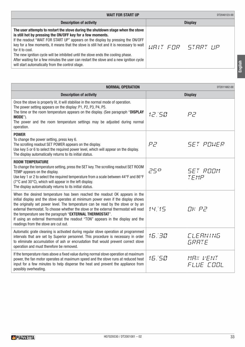
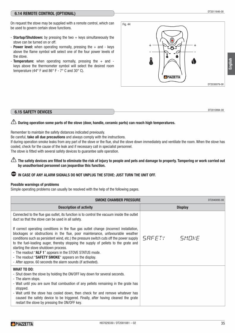
6.0 USE 236.1 Loading the pellets 236.2 Control panel 246.3 Setting the language 246.4 Programming 256.5 Setting unit of temperature measurement 266.6 Programming the clock 266.7 Timer 266.8 Energy Saving 296.9 Parameters menu 306.10 Buzzer enable 316.11 Display mode 316.12 Lighting for the first time 316.13 Start up and normal operation 326.14 Remote control (optional) 356.15 Safety devices 356.16 Stove status 386.17 Opening the door 386.18 Humidifier for stove 396.19 Disposal of ashes 39
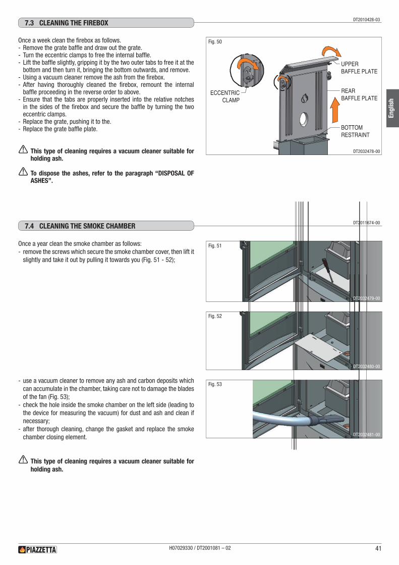
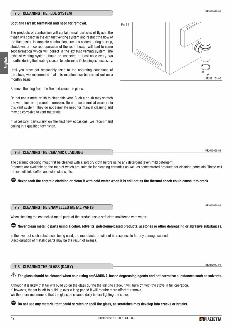
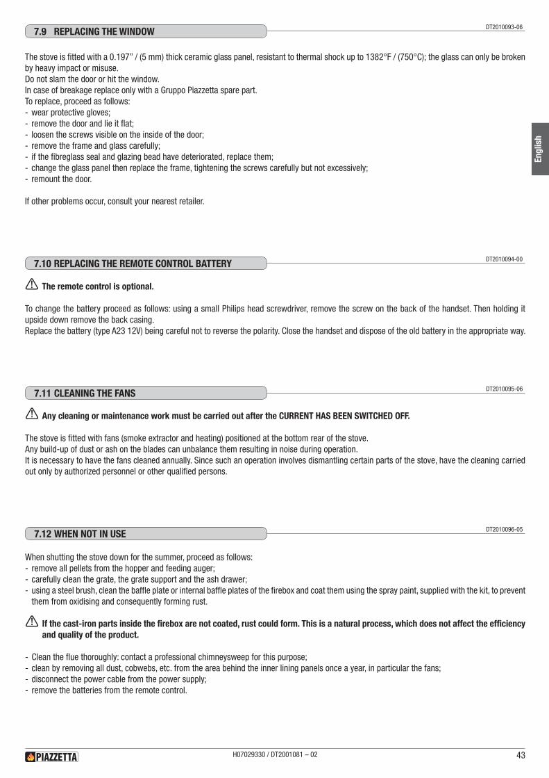
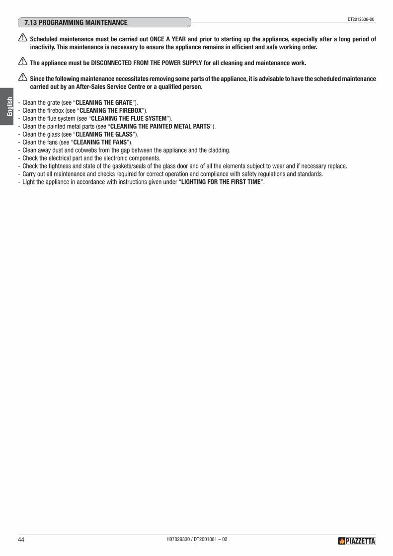
7.0 MAINTENANCE 407.1 Cleaning the grate and the grate support 407.2 Cleaning the ash tray 407.3 Cleaning the firebox 417.4 Cleaning the smoke chamber 417.5 Cleaning the flue system 427.6 Cleaning the ceramic cladding 427.7 Cleaning the enamelled metal parts 427.8 Cleaning the glass (daily) 427.9 Replacing the window 437.10 Replacing the remote control battery 437.11 Cleaning the fans 437.12 When not in use 437.13 Programming maintenance 44
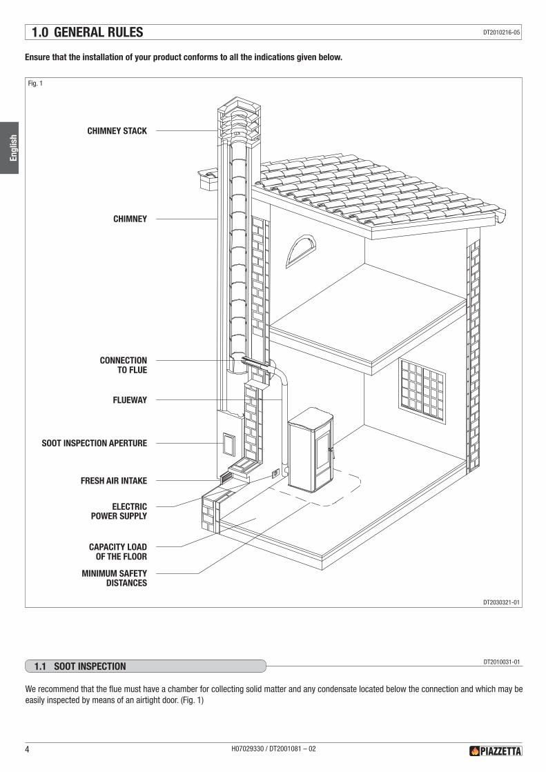
Ensure that the installation of your product conforms to all the indications given below.
SOOT INSPECTION APERTURE
CHIMNEY STACK
CHIMNEY
CONNECTIONTO FLUE
MINIMUM SAFETYDISTANCES
CAPACITY LOADOF THE FLOOR
FRESH AIR INTAKE
FLUEWAY
ELECTRICPOWER SUPPLY
Fig. 1
1.0 GENERAL RULES
We recommend that the flue must have a chamber for collecting solid matter and any condensate located below the connection and which may be easily inspected by means of an airtight door. (Fig. 1)
DT2010031-011.1 SOOT INSPECTION
H07029330 / DT2001081 – 024
Engl
ish
DT2010216-05
DT2030321-01
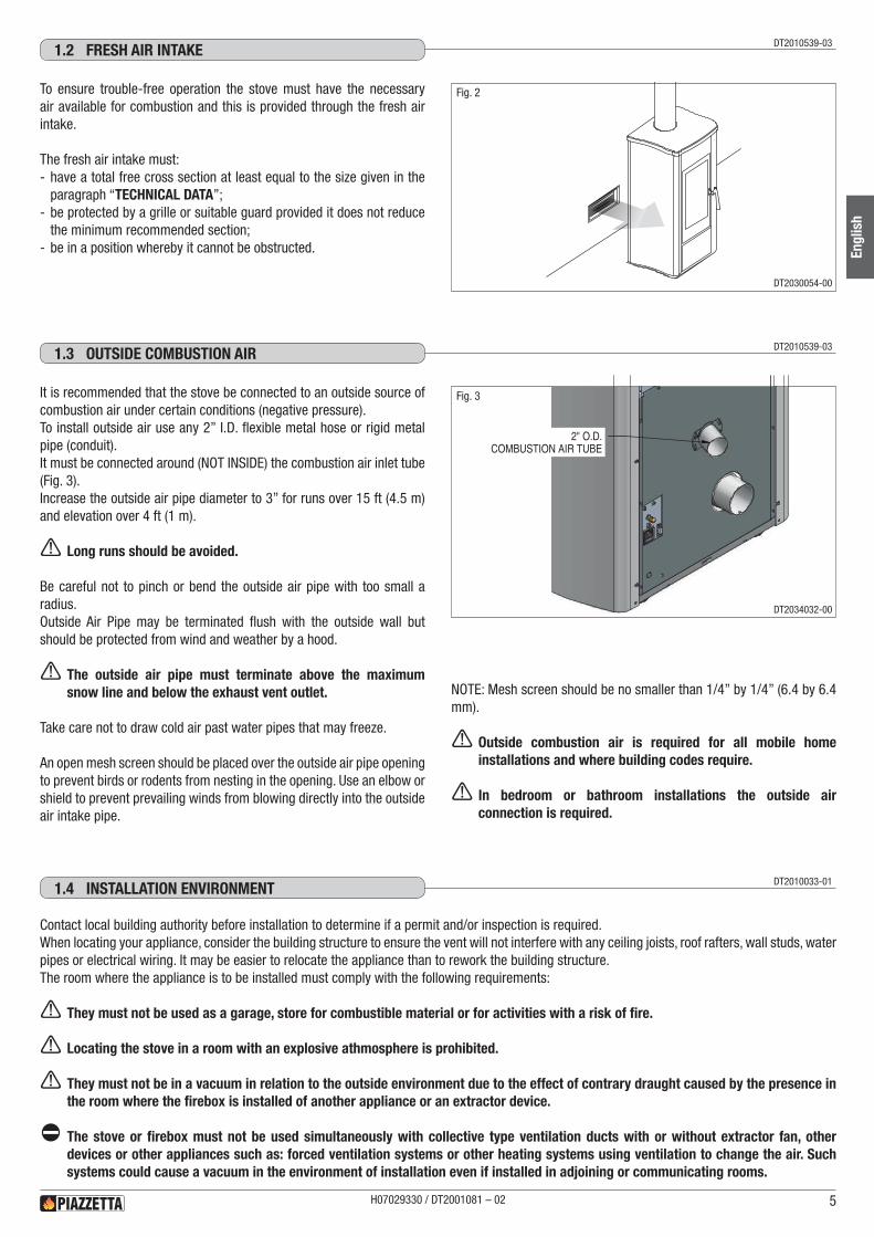
To ensure trouble-free operation the stove must have the necessary air available for combustion and this is provided through the fresh air intake.
The fresh air intake must: - have a total free cross section at least equal to the size given in the paragraph “TECHNICAL DATA”;
- be protected by a grille or suitable guard provided it does not reduce the minimum recommended section;
- be in a position whereby it cannot be obstructed.
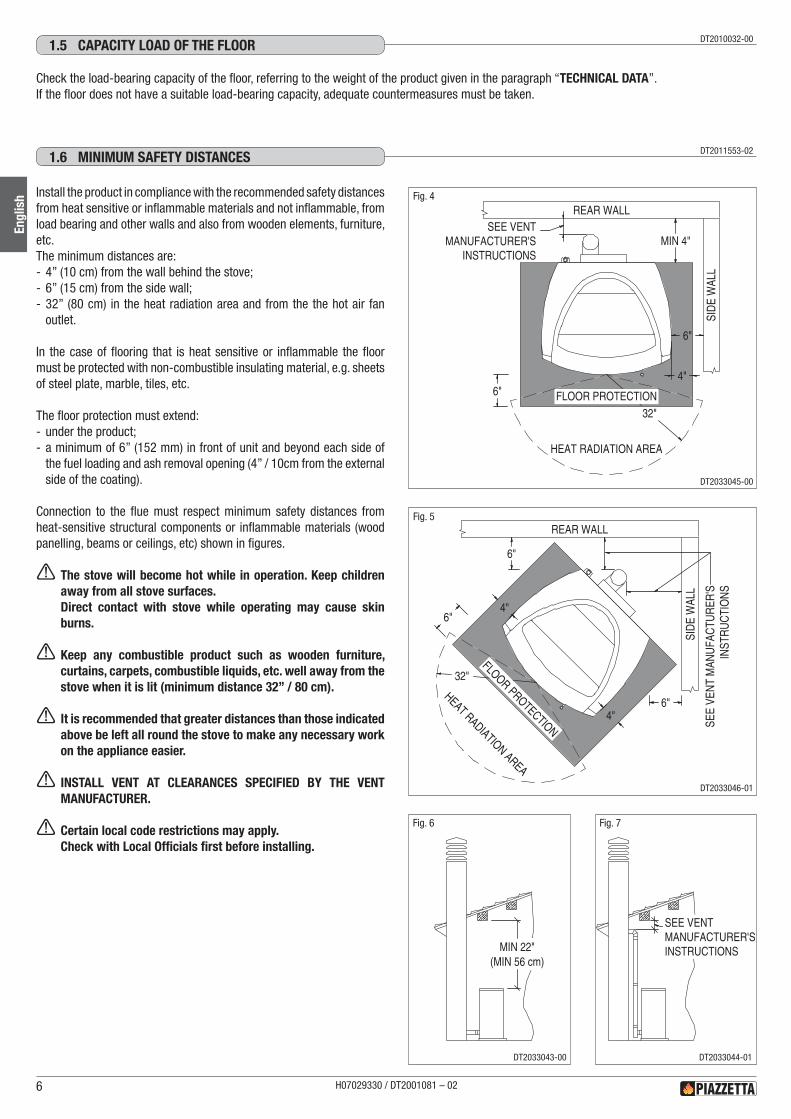
It is recommended that the stove be connected to an outside source of combustion air under certain conditions (negative pressure).To install outside air use any 2” I.D. flexible metal hose or rigid metal pipe (conduit).It must be connected around (NOT INSIDE) the combustion air inlet tube (Fig. 3).Increase the outside air pipe diameter to 3” for runs over 15 ft (4.5 m) and elevation over 4 ft (1 m).
a Long runs should be avoided.
Be careful not to pinch or bend the outside air pipe with too small a radius.Outside Air Pipe may be terminated flush with the outside wall but should be protected from wind and weather by a hood.
a The outside air pipe must terminate above the maximum snow line and below the exhaust vent outlet.
Take care not to draw cold air past water pipes that may freeze.
An open mesh screen should be placed over the outside air pipe opening to prevent birds or rodents from nesting in the opening. Use an elbow or shield to prevent prevailing winds from blowing directly into the outside air intake pipe.
Contact local building authority before installation to determine if a permit and/or inspection is required.When locating your appliance, consider the building structure to ensure the vent will not interfere with any ceiling joists, roof rafters, wall studs, water pipes or electrical wiring. It may be easier to relocate the appliance than to rework the building structure.The room where the appliance is to be installed must comply with the following requirements:
a They must not be used as a garage, store for combustible material or for activities with a risk of fire.
a Locating the stove in a room with an explosive athmosphere is prohibited.
a They must not be in a vacuum in relation to the outside environment due to the effect of contrary draught caused by the presence in the room where the firebox is installed of another appliance or an extractor device.
d The stove or firebox must not be used simultaneously with collective type ventilation ducts with or without extractor fan, other devices or other appliances such as: forced ventilation systems or other heating systems using ventilation to change the air. Such systems could cause a vacuum in the environment of installation even if installed in adjoining or communicating rooms.
DT2010539-031.2 FRESh AIR INTAkE
DT2010539-031.3 OUTSIdE COMbUSTION AIR
Fig. 2
DT2010033-011.4 INSTALLATION ENvIRONMENT
NOTE: Mesh screen should be no smaller than 1/4” by 1/4” (6.4 by 6.4 mm).
a Outside combustion air is required for all mobile home installations and where building codes require.
a In bedroom or bathroom installations the outside air connection is required.
2" O.D.COMBUSTION AIR TUBE
Fig. 3
H07029330 / DT2001081 – 02 5
Engl
ish
DT2030054-00
DT2034032-00
Check the load-bearing capacity of the floor, referring to the weight of the product given in the paragraph “TECHNICAL DATA”.If the floor does not have a suitable load-bearing capacity, adequate countermeasures must be taken.
DT2010032-001.5 CAPACITy LOAd OF ThE FLOOR
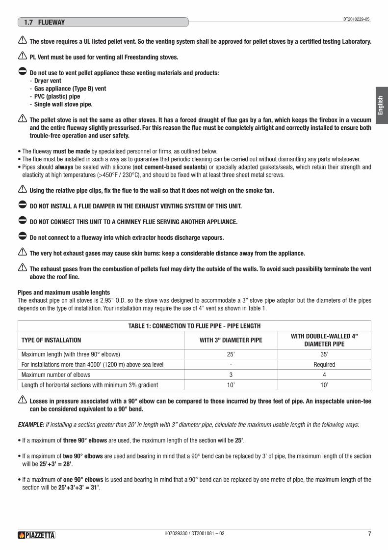
Install the product in compliance with the recommended safety distances from heat sensitive or inflammable materials and not inflammable, from load bearing and other walls and also from wooden elements, furniture, etc.The minimum distances are: - 4” (10 cm) from the wall behind the stove; - 6” (15 cm) from the side wall; - 32” (80 cm) in the heat radiation area and from the the hot air fan outlet.
In the case of flooring that is heat sensitive or inflammable the floor must be protected with non-combustible insulating material, e.g. sheets of steel plate, marble, tiles, etc.
The floor protection must extend: - under the product; - a minimum of 6” (152 mm) in front of unit and beyond each side of the fuel loading and ash removal opening (4” / 10cm from the external side of the coating).
Connection to the flue must respect minimum safety distances from heat-sensitive structural components or inflammable materials (wood panelling, beams or ceilings, etc) shown in figures.
a The stove will become hot while in operation. Keep children away from all stove surfaces.Direct contact with stove while operating may cause skin burns.
a Keep any combustible product such as wooden furniture, curtains, carpets, combustible liquids, etc. well away from the stove when it is lit (minimum distance 32” / 80 cm).
a It is recommended that greater distances than those indicated above be left all round the stove to make any necessary work on the appliance easier.
a INSTALL VENT AT CLEARANCES SPECIFIED BY THE VENT MANUFACTURER.
a Certain local code restrictions may apply.Check with Local Officials first before installing.
DT2011553-021.6 MINIMUM SAFETy dISTANCES
SEE VENTMANUFACTURER'S
INSTRUCTIONSMIN 4"
4"
6"
6"
32"FLOOR PROTECTION
REAR WALL
SID
E W
ALL
HEAT RADIATION AREA
6"
6"4"
4"6"
32"FLOOR PROTECTION
SID
E W
ALL
REAR WALL
SEE
VEN
T M
ANU
FAC
TUR
ER'S
INST
RU
CTI
ON
S
HEAT RADIATION AREA
Fig. 4
Fig. 5
SEE VENTMANUFACTURER'SINSTRUCTIONSMIN 22"
(MIN 56 cm)
Fig. 6 Fig. 7
H07029330 / DT2001081 – 026
Engl
ish
DT2033045-00
DT2033046-01
DT2033043-00 DT2033044-01
a The stove requires a UL listed pellet vent. So the venting system shall be approved for pellet stoves by a certified testing Laboratory.
a PL Vent must be used for venting all Freestanding stoves.
d Do not use to vent pellet appliance these venting materials and products: - Dryer vent - Gas appliance (Type B) vent - PVC (plastic) pipe - Single wall stove pipe.
a The pellet stove is not the same as other stoves. It has a forced draught of flue gas by a fan, which keeps the firebox in a vacuum and the entire flueway slightly pressurised. For this reason the flue must be completely airtight and correctly installed to ensure both trouble-free operation and user safety.
•The flueway must be made by specialised personnel or firms, as outlined below.•The flue must be installed in such a way as to guarantee that periodic cleaning can be carried out without dismantling any parts whatsoever.•Pipes should always be sealed with silicone (not cement-based sealants) or specially adapted gaskets/seals, which retain their strength and
elasticity at high temperatures (>450°F / 230°C), and should be fixed with at least three sheet metal screws.
a Using the relative pipe clips, fix the flue to the wall so that it does not weigh on the smoke fan.
d DO NOT INSTALL A FLUE DAMPER IN THE EXHAUST VENTING SYSTEM OF THIS UNIT.
d DO NOT CONNECT THIS UNIT TO A CHIMNEY FLUE SERVING ANOTHER APPLIANCE.
d Do not connect to a flueway into which extractor hoods discharge vapours.
a The very hot exhaust gases may cause skin burns: keep a considerable distance away from the appliance.
a The exhaust gases from the combustion of pellets fuel may dirty the outside of the walls. To avoid such possibility terminate the vent above the roof line.
Pipes and maximum usable lenghtsThe exhaust pipe on all stoves is 2.95” O.D. so the stove was designed to accommodate a 3” stove pipe adaptor but the diameters of the pipes depends on the type of installation. Your installation may require the use of 4” vent as shown in Table 1.
TABLE 1: CONNECTION TO FLUE PIPE - PIPE LENGTH
TYPE OF INSTALLATION WITH 3” DIAMETER PIPEWITH DOUBLE-WALLED 4”
DIAMETER PIPE
Maximum length (with three 90° elbows) 25’ 35’
For installations more than 4000’ (1200 m) above sea level - Required
Maximum number of elbows 3 4
Length of horizontal sections with minimum 3% gradient 10’ 10’
a Losses in pressure associated with a 90° elbow can be compared to those incurred by three feet of pipe. An inspectable union-tee can be considered equivalent to a 90° bend.
EXAMPLE: if installing a section greater than 20’ in length with 3” diameter pipe, calculate the maximum usable length in the following ways:
•If a maximum of three 90° elbows are used, the maximum length of the section will be 25’.
•If a maximum of two 90° elbows are used and bearing in mind that a 90° bend can be replaced by 3’ of pipe, the maximum length of the section will be 25’+3’ = 28’.
•If a maximum of one 90° elbows is used and bearing in mind that a 90° bend can be replaced by one metre of pipe, the maximum length of the section will be 25’+3’+3’ = 31’.
DT2010229-051.7 FLUEwAy
H07029330 / DT2001081 – 02 7
Engl
ish
H MIN 5'
H MIN 13'
INSULATINGMATERIAL
TEE
TEEDIRECTION
OF CLEANING
DIRECTIONOF CLEANING
DIRECTIONOF CLEANING
TEE
PELLETSTOVE
0 ÷ 10'
MIN 3%
SEE VENT MANUFACTURER'SINSTRUCTIONS
Fig. 9
Ø 4"
Ø 3"
TEE W/TEE CAP
PELLETSTOVE
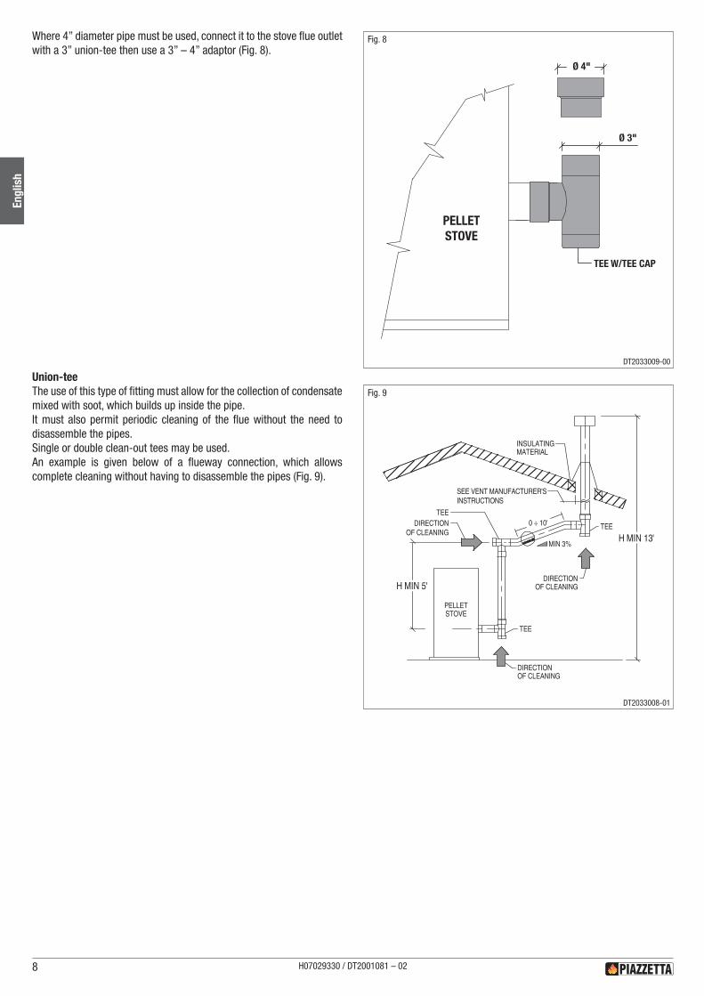
Fig. 8 Where 4” diameter pipe must be used, connect it to the stove flue outlet with a 3” union-tee then use a 3” – 4” adaptor (Fig. 8).
Union-teeThe use of this type of fitting must allow for the collection of condensate mixed with soot, which builds up inside the pipe.It must also permit periodic cleaning of the flue without the need to disassemble the pipes.Single or double clean-out tees may be used.An example is given below of a flueway connection, which allows complete cleaning without having to disassemble the pipes (Fig. 9).
H07029330 / DT2001081 – 028
Engl
ish
DT2033008-01
DT2033009-00
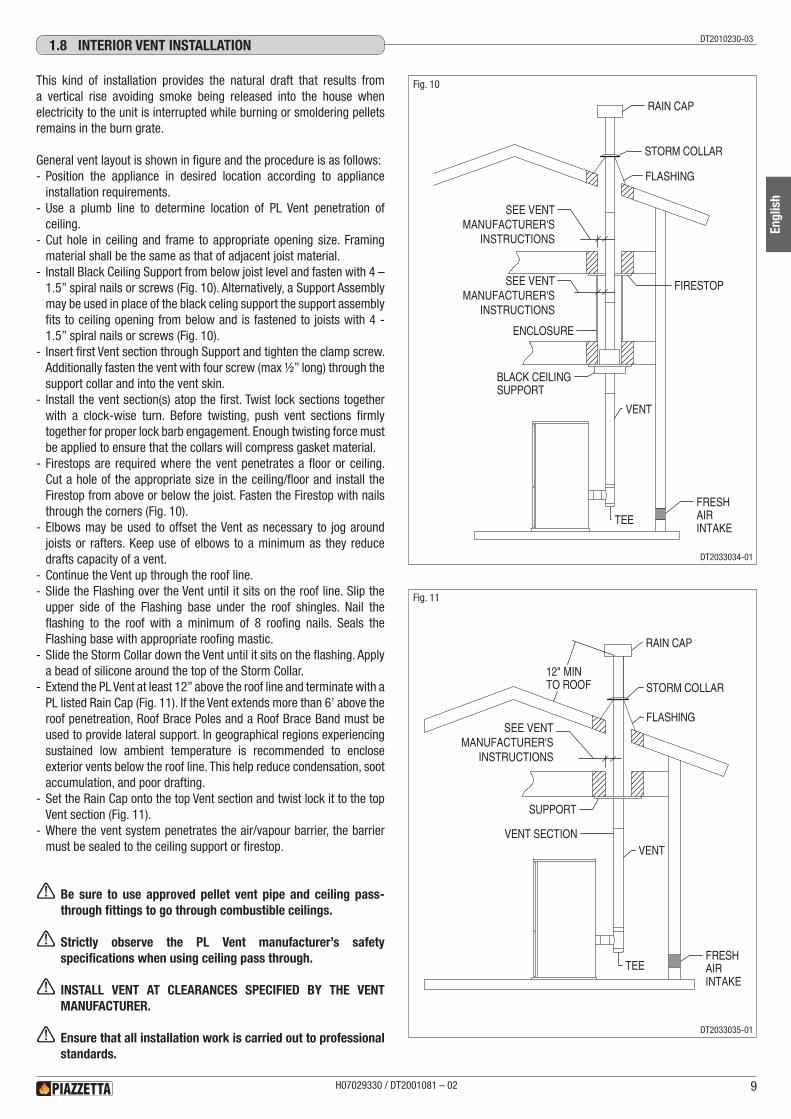
This kind of installation provides the natural draft that results from a vertical rise avoiding smoke being released into the house when electricity to the unit is interrupted while burning or smoldering pellets remains in the burn grate.
General vent layout is shown in figure and the procedure is as follows: - Position the appliance in desired location according to appliance installation requirements.
- Use a plumb line to determine location of PL Vent penetration of ceiling.
- Cut hole in ceiling and frame to appropriate opening size. Framing material shall be the same as that of adjacent joist material.
- Install Black Ceiling Support from below joist level and fasten with 4 – 1.5” spiral nails or screws (Fig. 10). Alternatively, a Support Assembly may be used in place of the black celing support the support assembly fits to ceiling opening from below and is fastened to joists with 4 - 1.5” spiral nails or screws (Fig. 10).
- Insert first Vent section through Support and tighten the clamp screw. Additionally fasten the vent with four screw (max ½” long) through the support collar and into the vent skin.
- Install the vent section(s) atop the first. Twist lock sections together with a clock-wise turn. Before twisting, push vent sections firmly together for proper lock barb engagement. Enough twisting force must be applied to ensure that the collars will compress gasket material.
- Firestops are required where the vent penetrates a floor or ceiling. Cut a hole of the appropriate size in the ceiling/floor and install the Firestop from above or below the joist. Fasten the Firestop with nails through the corners (Fig. 10).
- Elbows may be used to offset the Vent as necessary to jog around joists or rafters. Keep use of elbows to a minimum as they reduce drafts capacity of a vent.
- Continue the Vent up through the roof line. - Slide the Flashing over the Vent until it sits on the roof line. Slip the upper side of the Flashing base under the roof shingles. Nail the flashing to the roof with a minimum of 8 roofing nails. Seals the Flashing base with appropriate roofing mastic.
- Slide the Storm Collar down the Vent until it sits on the flashing. Apply a bead of silicone around the top of the Storm Collar.
- Extend the PL Vent at least 12” above the roof line and terminate with a PL listed Rain Cap (Fig. 11). If the Vent extends more than 6’ above the roof penetreation, Roof Brace Poles and a Roof Brace Band must be used to provide lateral support. In geographical regions experiencing sustained low ambient temperature is recommended to enclose exterior vents below the roof line. This help reduce condensation, soot accumulation, and poor drafting.
- Set the Rain Cap onto the top Vent section and twist lock it to the top Vent section (Fig. 11).
- Where the vent system penetrates the air/vapour barrier, the barrier must be sealed to the ceiling support or firestop.
a Be sure to use approved pellet vent pipe and ceiling pass-through fittings to go through combustible ceilings.
a Strictly observe the PL Vent manufacturer’s safety specifications when using ceiling pass through.
a INSTALL VENT AT CLEARANCES SPECIFIED BY THE VENT MANUFACTURER.
a Ensure that all installation work is carried out to professional standards.
DT2010230-031.8 INTERIOR vENT INSTALLATION
FIRESTOP
ENCLOSURE
BLACK CEILINGSUPPORT
VENT
TEE
FRESHAIRINTAKE
RAIN CAP
STORM COLLAR
FLASHING
SEE VENTMANUFACTURER'S
INSTRUCTIONS
SEE VENTMANUFACTURER'S
INSTRUCTIONS
SUPPORT
RAIN CAP
STORM COLLAR
FLASHING
VENT SECTIONVENT
TEEFRESHAIRINTAKE
12" MINTO ROOF
SEE VENTMANUFACTURER'S
INSTRUCTIONS
Fig. 10
Fig. 11
H07029330 / DT2001081 – 02 9
Engl
ish
DT2033034-01
DT2033035-01
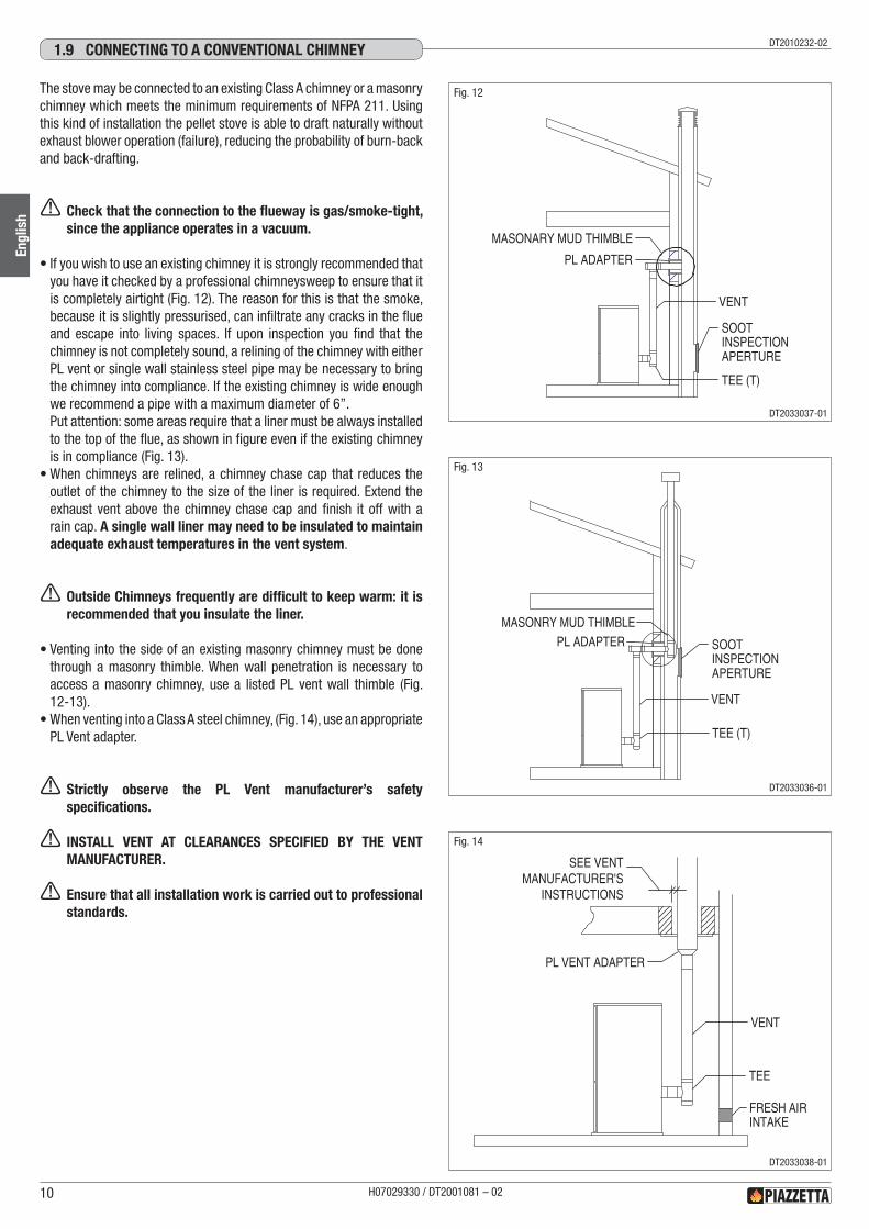
The stove may be connected to an existing Class A chimney or a masonry chimney which meets the minimum requirements of NFPA 211. Using this kind of installation the pellet stove is able to draft naturally without exhaust blower operation (failure), reducing the probability of burn-back and back-drafting.
a Check that the connection to the flueway is gas/smoke-tight, since the appliance operates in a vacuum.
•If you wish to use an existing chimney it is strongly recommended that you have it checked by a professional chimneysweep to ensure that it is completely airtight (Fig. 12). The reason for this is that the smoke, because it is slightly pressurised, can infiltrate any cracks in the flue and escape into living spaces. If upon inspection you find that the chimney is not completely sound, a relining of the chimney with either PL vent or single wall stainless steel pipe may be necessary to bring the chimney into compliance. If the existing chimney is wide enough we recommend a pipe with a maximum diameter of 6”.Put attention: some areas require that a liner must be always installed to the top of the flue, as shown in figure even if the existing chimney is in compliance (Fig. 13).
•When chimneys are relined, a chimney chase cap that reduces the outlet of the chimney to the size of the liner is required. Extend the exhaust vent above the chimney chase cap and finish it off with a rain cap. A single wall liner may need to be insulated to maintain adequate exhaust temperatures in the vent system.
a Outside Chimneys frequently are difficult to keep warm: it is recommended that you insulate the liner.
•Venting into the side of an existing masonry chimney must be done through a masonry thimble. When wall penetration is necessary to access a masonry chimney, use a listed PL vent wall thimble (Fig. 12-13).
•When venting into a Class A steel chimney, (Fig. 14), use an appropriate PL Vent adapter.
a Strictly observe the PL Vent manufacturer’s safety specifications.
a INSTALL VENT AT CLEARANCES SPECIFIED BY THE VENT MANUFACTURER.
a Ensure that all installation work is carried out to professional standards.
DT2010232-021.9 CONNECTING TO A CONvENTIONAL ChIMNEy
MASONARY MUD THIMBLE
PL ADAPTER
TEE (T)
VENT
SOOT INSPECTIONAPERTURE
PL ADAPTER
TEE (T)
VENT
MASONRY MUD THIMBLE
SOOT INSPECTIONAPERTURE
TEE
FRESH AIRINTAKE
VENT
PL VENT ADAPTER
SEE VENTMANUFACTURER'S
INSTRUCTIONS
Fig. 12
Fig. 13
Fig. 14
H07029330 / DT2001081 – 0210
Engl
ish
DT2033037-01
DT2033036-01
DT2033038-01
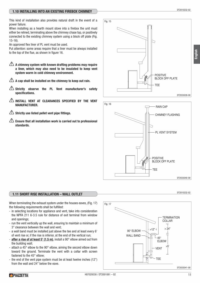
This kind of installation also provides natural draft in the event of a power failure.When installing as a hearth mount stove into a firebox the unit must either be relined, terminating above the chimney chase top, or positively connected to the existing chimney system using a block off plate (Fig. 15-16).An approved flex liner of PL vent must be used.Put attention: some areas require that a liner must be always installed to the top of the flue, as shown in figure 16.
a A chimney system with known drafting problems may require a liner, which may also need to be insulated to keep vent system warm in cold chimney environment.
a A cap shall be installed on the chimney to keep out rain.
a Strictly observe the PL Vent manufacturer’s safety specifications.
a INSTALL VENT AT CLEARANCES SPECIFIED BY THE VENT MANUFACTURER.
a Strictly use listed pellet vent pipe fittings.
a Ensure that all installation work is carried out to professional standards.
When terminating the exhaust system under the houses eaves, (Fig. 17) the following requirements shall be fulfilled: - in selecting locations for appliance and vent, take into consideration the NPFA 211 6-3.5 rule for distance of exit terminal from window and openings;
- run the vent vertically up the wall, ensuring to maintain a minimum of 3” clearance between the wall and vent;
- a wall band must be installed just above the tee and at least every 6’ of vent rise or, if the rise is inferior, at the end of the vertical run;
- after a rise of at least 5’ (1.5 m), install a 90° elbow aimed out from the building wall;
- attach a 45° elbow to the 90° elbow, aiming the second elbow down toward the ground. Terminate the vent with a collar with screen fastened to the 45° elbow;
- the end of the vent pipe system must be at least twelve inches (12”) from the wall and 24” below the eave.
DT2010232-021.10 INSTALLING INTO AN ExISTING FIREbOx ChIMNEy
DT2010232-021.11 ShORT RISE INSTALLATION – wALL OUTLET
TEE
POSITIVEBLOCK OFF PLATE
TEE
POSITIVEBLOCK OFF PLATE
RAIN CAP
CHIMNEY FLASHING
PL VENT SYSTEM
> 24"
>5'
>12"
45°ELBOW
90° ELBOW
TERMINATIONCOLLAR
TEE
VENT
WALL BAND
Fig. 15
Fig. 16
Fig. 17
H07029330 / DT2001081 – 02 11
Engl
ish
DT2033039-00
DT2033040-00
DT2033041-00
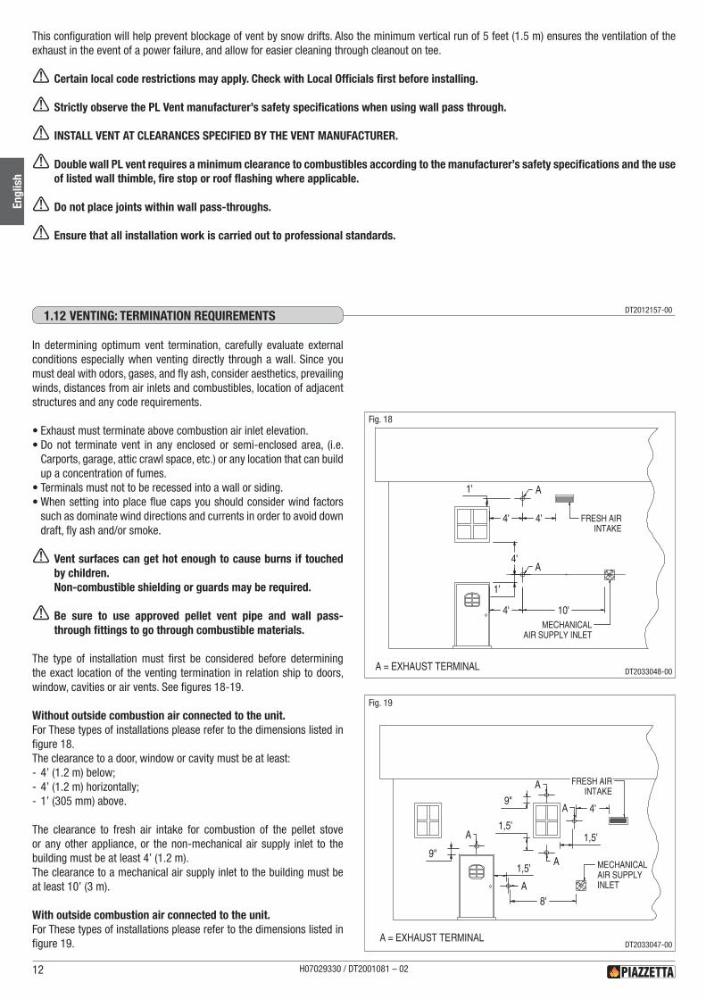
In determining optimum vent termination, carefully evaluate external conditions especially when venting directly through a wall. Since you must deal with odors, gases, and fly ash, consider aesthetics, prevailing winds, distances from air inlets and combustibles, location of adjacent structures and any code requirements.
•Exhaust must terminate above combustion air inlet elevation.•Do not terminate vent in any enclosed or semi-enclosed area, (i.e.
Carports, garage, attic crawl space, etc.) or any location that can build up a concentration of fumes.
•Terminals must not to be recessed into a wall or siding.•When setting into place flue caps you should consider wind factors
such as dominate wind directions and currents in order to avoid down draft, fly ash and/or smoke.
a Vent surfaces can get hot enough to cause burns if touched by children.Non-combustible shielding or guards may be required.
a Be sure to use approved pellet vent pipe and wall pass- through fittings to go through combustible materials.
The type of installation must first be considered before determining the exact location of the venting termination in relation ship to doors, window, cavities or air vents. See figures 18-19.
Without outside combustion air connected to the unit.For These types of installations please refer to the dimensions listed in figure 18.The clearance to a door, window or cavity must be at least: - 4’ (1.2 m) below; - 4’ (1.2 m) horizontally; - 1’ (305 mm) above.
The clearance to fresh air intake for combustion of the pellet stove or any other appliance, or the non-mechanical air supply inlet to the building must be at least 4’ (1.2 m).The clearance to a mechanical air supply inlet to the building must be at least 10’ (3 m).
With outside combustion air connected to the unit.For These types of installations please refer to the dimensions listed in figure 19.
This configuration will help prevent blockage of vent by snow drifts. Also the minimum vertical run of 5 feet (1.5 m) ensures the ventilation of the exhaust in the event of a power failure, and allow for easier cleaning through cleanout on tee.
a Certain local code restrictions may apply. Check with Local Officials first before installing.
a Strictly observe the PL Vent manufacturer’s safety specifications when using wall pass through.
a INSTALL VENT AT CLEARANCES SPECIFIED BY THE VENT MANUFACTURER.
a Double wall PL vent requires a minimum clearance to combustibles according to the manufacturer’s safety specifications and the use of listed wall thimble, fire stop or roof flashing where applicable.
a Do not place joints within wall pass-throughs.
a Ensure that all installation work is carried out to professional standards.
H07029330 / DT2001081 – 0212
Engl
ish
DT2033048-00
DT2033047-00
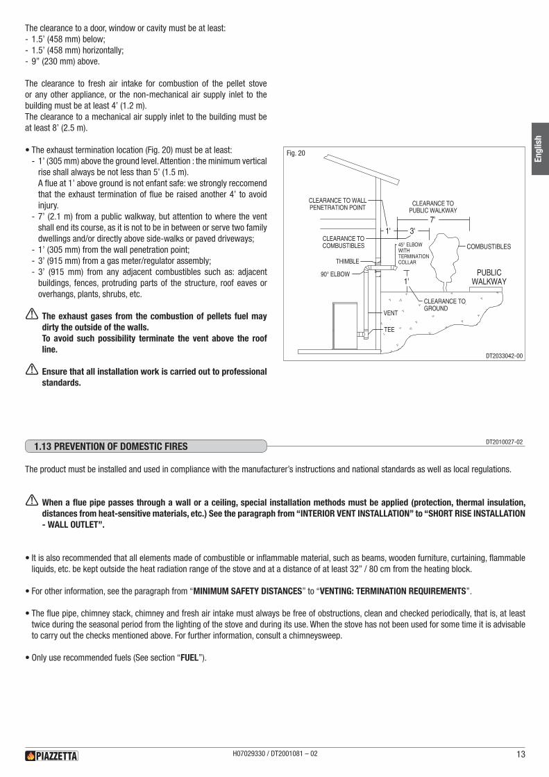
The clearance to a door, window or cavity must be at least: - 1.5’ (458 mm) below; - 1.5’ (458 mm) horizontally; - 9’’ (230 mm) above.
The clearance to fresh air intake for combustion of the pellet stove or any other appliance, or the non-mechanical air supply inlet to the building must be at least 4’ (1.2 m).The clearance to a mechanical air supply inlet to the building must be at least 8’ (2.5 m).
•The exhaust termination location (Fig. 20) must be at least: - 1’ (305 mm) above the ground level. Attention : the minimum vertical rise shall always be not less than 5’ (1.5 m).A flue at 1’ above ground is not enfant safe: we strongly reccomend that the exhaust termination of flue be raised another 4’ to avoid injury.
- 7’ (2.1 m) from a public walkway, but attention to where the vent shall end its course, as it is not to be in between or serve two family dwellings and/or directly above side-walks or paved driveways;
- 1’ (305 mm) from the wall penetration point; - 3’ (915 mm) from a gas meter/regulator assembly; - 3’ (915 mm) from any adjacent combustibles such as: adjacent buildings, fences, protruding parts of the structure, roof eaves or overhangs, plants, shrubs, etc.
a The exhaust gases from the combustion of pellets fuel may dirty the outside of the walls. To avoid such possibility terminate the vent above the roof line.
a Ensure that all installation work is carried out to professional standards.
PUBLICWALKWAY
1' 3'7'
1'
COMBUSTIBLES
CLEARANCE TOPUBLIC WALKWAY
CLEARANCE TO WALLPENETRATION POINT
CLEARANCE TOCOMBUSTIBLES
CLEARANCE TOGROUND
TEE
VENT
90° ELBOW
THIMBLE
45° ELBOWWITHTERMINATIONCOLLAR
Fig. 20
The product must be installed and used in compliance with the manufacturer’s instructions and national standards as well as local regulations.
a When a flue pipe passes through a wall or a ceiling, special installation methods must be applied (protection, thermal insulation, distances from heat-sensitive materials, etc.) See the paragraph from “INTERIOR VENT INSTALLATION” to “SHORT RISE INSTALLATION - WALL OUTLET”.
•It is also recommended that all elements made of combustible or inflammable material, such as beams, wooden furniture, curtaining, flammable liquids, etc. be kept outside the heat radiation range of the stove and at a distance of at least 32” / 80 cm from the heating block.
•For other information, see the paragraph from “MINIMUM SAFETY DISTANCES” to “VENTING: TERMINATION REQUIREMENTS”.
•The flue pipe, chimney stack, chimney and fresh air intake must always be free of obstructions, clean and checked periodically, that is, at least twice during the seasonal period from the lighting of the stove and during its use. When the stove has not been used for some time it is advisable to carry out the checks mentioned above. For further information, consult a chimneysweep.
•Only use recommended fuels (See section “FUEL”).
DT2010027-021.13 PREvENTION OF dOMESTIC FIRES
H07029330 / DT2001081 – 02 13
Engl
ish
DT2033042-00
B
A
FLOOR
FLOORPROTECTION
METAL CHASSIS
Fig. 21
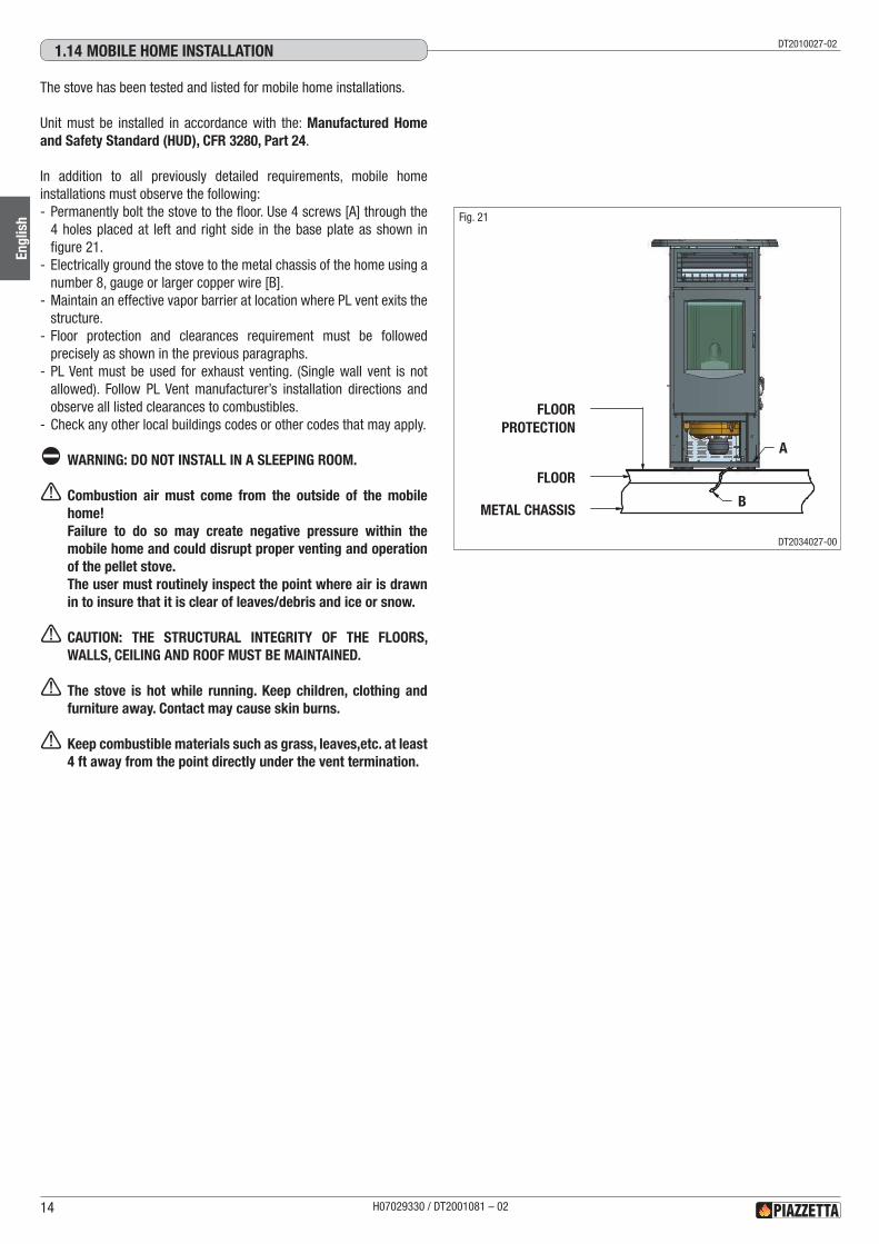
The stove has been tested and listed for mobile home installations.
Unit must be installed in accordance with the: Manufactured Home and Safety Standard (HUD), CFR 3280, Part 24.
In addition to all previously detailed requirements, mobile home installations must observe the following: - Permanently bolt the stove to the floor. Use 4 screws [A] through the 4 holes placed at left and right side in the base plate as shown in figure 21.
- Electrically ground the stove to the metal chassis of the home using a number 8, gauge or larger copper wire [B].
- Maintain an effective vapor barrier at location where PL vent exits the structure.
- Floor protection and clearances requirement must be followed precisely as shown in the previous paragraphs.
- PL Vent must be used for exhaust venting. (Single wall vent is not allowed). Follow PL Vent manufacturer’s installation directions and observe all listed clearances to combustibles.
- Check any other local buildings codes or other codes that may apply.
d WARNING: DO NOT INSTALL IN A SLEEPING ROOM.
a Combustion air must come from the outside of the mobile home!Failure to do so may create negative pressure within the mobile home and could disrupt proper venting and operation of the pellet stove.The user must routinely inspect the point where air is drawn in to insure that it is clear of leaves/debris and ice or snow.
a CAUTION: THE STRUCTURAL INTEGRITY OF THE FLOORS, WALLS, CEILING AND ROOF MUST BE MAINTAINED.
a The stove is hot while running. Keep children, clothing and furniture away. Contact may cause skin burns.
a Keep combustible materials such as grass, leaves,etc. at least 4 ft away from the point directly under the vent termination.
DT2010027-021.14 MObILE hOME INSTALLATION
H07029330 / DT2001081 – 0214
Engl
ish
DT2034027-00
2.0 TEChNICAL ChARACTERISTICS ANd SPECIFICATIONS
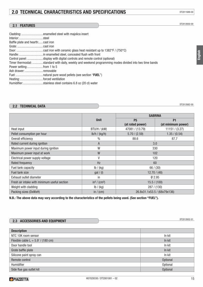
Cladding: ..........................enamelled steel with majolica insertInterior: .............................steelBaffle plate and hearth: .....cast ironGrate: ...............................cast ironDoor: ................................cast iron with ceramic glass heat resistant up to 1382°F / (750°C)Handle: ............................. in enamelled steel, concealed flush with front Control panel: ...................display with digital controls and remote control (optional)Timer thermostat: .............standard with daily, weekly and weekend programming modes divided into two time bandsPower setting: ................... from 1 to 5Ash drawer: ...................... removableFuel: .................................natural pure wood pellets (see section “FUEL”)Heating: ............................ forced ventilationHumidifier: ........................stainless steel contains 6.8 oz (20 cl) water
N.B.: The above data may vary according to the characteristics of the pellets being used. (See section “FUEL”).
UnitSABRINA
P5(at rated power)
P1(at minimum power)
Heat input BTU/H / (kW) 47081 / (13.79) 11151 / (3.27)Pellet consumption per hour lb/h / (kg/h) 5.70 / (2.59) 1.35 / (0.54)Overall efficiency % 88.6 87.7Rated current during ignition A 3.0Maximum power input during ignition W 330Maximum power input at work W 102Electrical power supply voltage V 120Rated frequency Hz 60Fuel tank capacity lb / (kg) 66 / (30)Fuel tank size gal / (l) 12.70 / (48)Exhaust outlet diameter in Ø 2.95Fresh air intake with minimum useful section in² / (cm²) 15.5 / (100)Weight with cladding lb / (kg) 287 / (130)Packing sizes (DxWxH) in / (cm) 26.8x31.1x53.5 / (68x79x136)
DT2012650-002.1 FEATURES
DT2012682-002.2 TEChNICAL dATA
DescriptionNTC 10K room sensor In kitFlexible cable L = 5.9’ / (180 cm) In kitDoor handle tool In kitGrate baffle plate In kitSilicone paint spray can In kitRemote control OptionalHumidifier OptionalSide flue gas outlet kit Optional
DT2012652-012.3 ACCESSORIES ANd EqUIPMENT
H07029330 / DT2001081 – 02 15
Engl
ish
DT2011689-00
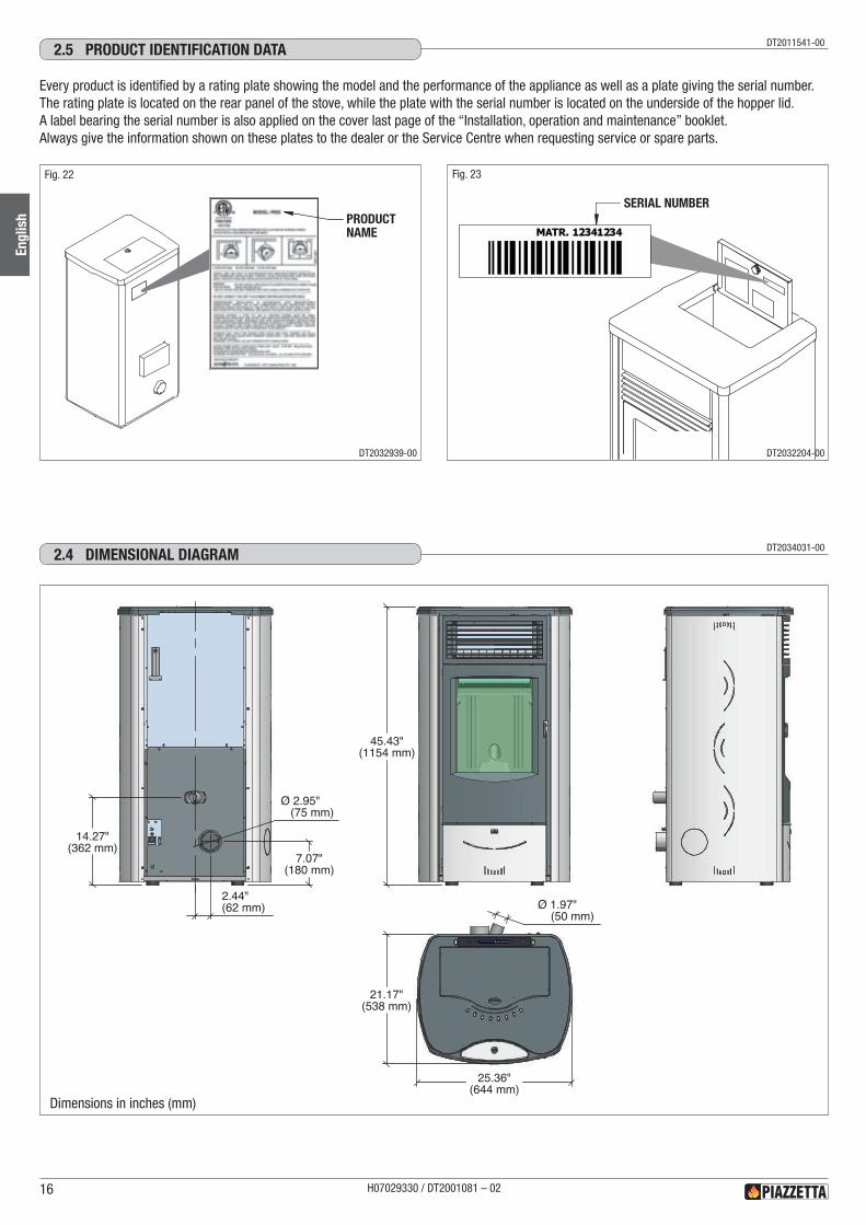
DT2034031-002.4 dIMENSIONAL dIAGRAM
14.27"(362 mm)
7.07"(180 mm)
2.44"(62 mm)
Ø 2.95" (75 mm)
45.43"(1154 mm)
21.17"(538 mm)
25.36"(644 mm)
Ø 1.97" (50 mm)
Every product is identified by a rating plate showing the model and the performance of the appliance as well as a plate giving the serial number.The rating plate is located on the rear panel of the stove, while the plate with the serial number is located on the underside of the hopper lid. A label bearing the serial number is also applied on the cover last page of the “Installation, operation and maintenance” booklet.Always give the information shown on these plates to the dealer or the Service Centre when requesting service or spare parts.
DT2011541-002.5 PROdUCT IdENTIFICATION dATA
PRODUCTNAME
SERIAL NUMBER
DT2032939-00 DT2032204-00
Fig. 22 Fig. 23
H07029330 / DT2001081 – 0216
Engl
ish
Dimensions in inches (mm)
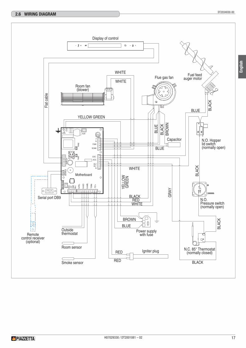
DT2034030-002.6 wIRING dIAGRAM
AL1N
AL2
ACC.
COC.
FUMI
SCAM.
FN
SER
IALE
TER
M.
-TC
1+
N.A
MB.
N.H
2O
N.P
EL.
BLU
GN
D+5
VEN
C
FAN
1FA
N2
DIS
PLAY
AUX
Display of control
Flat
cab
le
Room fan(blower)
Fuel feedauger motorFlue gas fan
Capacitor
N.O.Pressure switch(normally open)
N.C. 85° Thermostat(normally closed)Igniter plug
Power supplywith fuse
Smoke sensor
Room sensor
Outsidethermostat
Serial port DB9
Motherboard
N.O. Hopperlid switch(normally open)
RED
RED
BLUE BLAC
K
WHITE
BLAC
K
BLAC
K
GR
AY
BLACK
BROWN
BLUE
YELL
OW
GR
EEN
YELLOW GREEN
BRO
WN
BLAC
KBL
UE
BLUE
WHITE
WHITE
Remotecontrol receiver
(optional)
REDBLACK
WHITE
H07029330 / DT2001081 – 02 17
Engl
ish
The wood pellet is obtained by pressing wood sawdust left over from the working of natural dried wood. The typical small, cylindrical form is obtained by passing the material through a die. Thanks to lignin, a natural element which is released during the pressing of the raw material, the pellets acquire a good consistency and compactness without requiring treatment with additives or caking agents.There are various types of pellet on the market with qualities and characteristics that vary depending on the processes they have undergone and the type of wood used in their production.
Since the characteristics and quality of the pellet considerably affect stove performance, efficiency and proper operation, we recommend that you use high-quality pellets.Gruppo Piazzetta S.p.A has tested and programmed its stoves and can ensure best performance and trouble-free operation using pellets with the following specific characteristics:
To ensure trouble-free operation:DO NOT use pellets with dimensions other than those recommended by the manufacturer.DO NOT use poor quality pellets containing sawdust, bark, maize, resins or chemical substances, additives or adhesives.DO NOT use damp pellets.
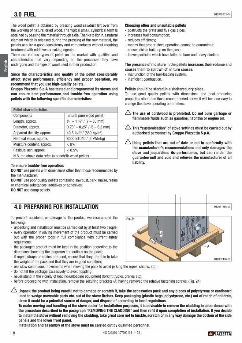
To prevent accidents or damage to the product we recommend the following: - unpacking and installation must be carried out by at least two people; - every operation involving movement of the product must be carried out with the proper tools in full compliance with current safety regulations;
- the packaged product must be kept in the position according to the directions shown by the diagrams and notices on the pack;
- if ropes, straps or chains are used, ensure that they are able to take the weight of the pack and that they are in good condition;
- use slow continuous movements when moving the pack to avoid jerking the ropes, chains, etc.; - do not tilt the package excessively to avoid toppling; - never stand in the vicinity of loading/unloading equipment (forklift trucks, cranes etc); - before proceeding with installation, remove the securing brackets (A) having removed the relative fastening screws. (Fig. 24)
a Unpack the product being careful not to damage or scratch it, take the accessories pack and any pieces of polystyrene or cardboard used to wedge moveable parts etc. out of the stove firebox. Keep packaging (plastic bags, polystyrene, etc.) out of reach of children, since it could be a potential source of danger, and dispose of according to local regulations.To make moving and handling of the stove easier for installation purposes, it is advisable to remove the cladding in accordance with the procedure described in the paragraph “REMOVING THE CLADDING” and then refit it upon completion of installation. If you decide to install the stove without removing the cladding, take great care not to buckle, scratch or in any way damage the bottom of the side panels and the lower front panel.Installation and assembly of the stove must be carried out by qualified personnel.
Choosing other and unsuitable pellets - obstructs the grate and flue gas pipes; - increases fuel consumption; - reduces efficiency; - means that proper stove operation cannot be guaranteed; - causes dirt to build up on the glass; - leaves particles which have failed to burn and heavy cinders.
The presence of moisture in the pellets increases their volume and causes them to split which in turn causes: - malfunction of the fuel-loading system; - inefficient combustion.
Pellets should be stored in a sheltered, dry place.To use good quality pellets with dimensions and heat-producing properties other than those recommended above, it will be necessary to change the stove operating parameters.
a The use of cordwood is prohibited. Do not burn garbage or flammable fluids such as gasoline, naphtha or engine oil.
a This “customisation” of stove settings must be carried out by authorised personnel by Gruppo Piazzetta S.p.A.
a Using pellets that are out of date or not in conformity with the manufacturer’s recommendations not only damages the stove and jeopardises its performance, but can render the guarantee null and void and relieves the manufacturer of all liability.
3.0 FUEL
4.0 PREPARING FOR INSTALLATION
A
A
Fig. 24
H07029330 / DT2001081 – 0218
Engl
ish
DT2010233-04
DT2011688-00
DT2032460-00
Pursuant to current regulations on the safety of electrical equipment, you must contact your dealer or a qualified electrician for all and any work connected with installation, maintenance or servicing that involves access to electrical parts.
Cladding•Having completed assembly of the stove and installed any external
room thermostat, check that the humidifier (optional) is properly inserted into its seat (see the paragraph “HUMIDIFIER”) and finally fit the ceramic panel into the top. (Fig. 25)
5.0 INSTALLATION
Fig. 25
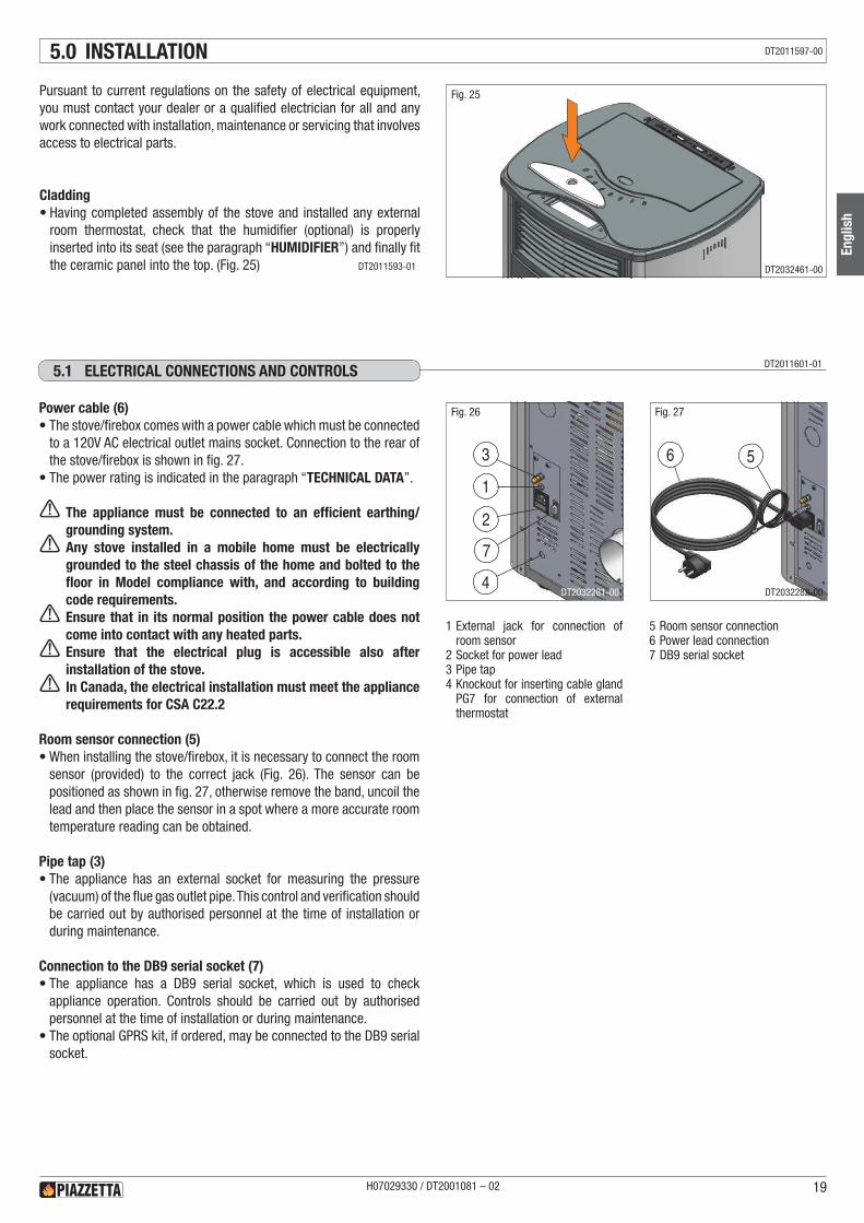
Power cable (6)•The stove/firebox comes with a power cable which must be connected
to a 120V AC electrical outlet mains socket. Connection to the rear of the stove/firebox is shown in fig. 27.
•The power rating is indicated in the paragraph “TECHNICAL DATA”.
a The appliance must be connected to an efficient earthing/grounding system. a Any stove installed in a mobile home must be electrically grounded to the steel chassis of the home and bolted to the floor in Model compliance with, and according to building code requirements. a Ensure that in its normal position the power cable does not come into contact with any heated parts. a Ensure that the electrical plug is accessible also after installation of the stove. a In Canada, the electrical installation must meet the appliance requirements for CSA C22.2
Room sensor connection (5)•When installing the stove/firebox, it is necessary to connect the room
sensor (provided) to the correct jack (Fig. 26). The sensor can be positioned as shown in fig. 27, otherwise remove the band, uncoil the lead and then place the sensor in a spot where a more accurate room temperature reading can be obtained.
Pipe tap (3)•The appliance has an external socket for measuring the pressure
(vacuum) of the flue gas outlet pipe. This control and verification should be carried out by authorised personnel at the time of installation or during maintenance.
Connection to the DB9 serial socket (7)•The appliance has a DB9 serial socket, which is used to check
appliance operation. Controls should be carried out by authorised personnel at the time of installation or during maintenance.
•The optional GPRS kit, if ordered, may be connected to the DB9 serial socket.
1 External jack for connection of room sensor
2 Socket for power lead3 Pipe tap4 Knockout for inserting cable gland
PG7 for connection of external thermostat
5 Room sensor connection6 Power lead connection7 DB9 serial socket
DT2011601-015.1 ELECTRICAL CONNECTIONS ANd CONTROLS
1
2
3
7
4
56
Fig. 26 Fig. 27
H07029330 / DT2001081 – 02 19
Engl
ish
DT2011597-00
DT2011593-01 DT2032461-00
DT2032281-00 DT2032282-00
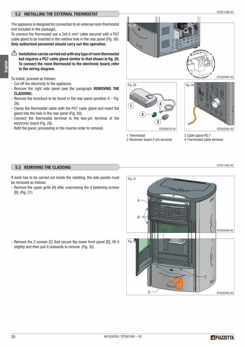
The appliance is designed for connection to an external room thermostat (not included in the package).To connect the thermostat use a 2x0.5 mm2 cable secured with a PG7 cable gland to be inserted in the relative hole in the rear panel (Fig. 30).Only authorised personnel should carry out this operation.
a Installation can be carried out with any type of room thermostat but requires a PG7 cable gland similar to that shown in fig. 29. To connect the room thermostat to the electronic board, refer to the wiring diagram.
To install, proceed as follows: - Cut off the electricity to the appliance. - Remove the right side panel (see the paragraph REMOVING THE CLADDING).
- Remove the knockout to be found in the rear panel (position 4 – Fig. 26).
- Clamp the thermostat cable with the PG7 cable gland and insert the gland into the hole in the rear panel (Fig. 30).
- Connect the thermostat terminal to the two-pin terminal of the electronic board (Fig. 28).
- Refit the panel, proceeding in the reverse order to removal.
DT2011598-005.2 INSTALLING ThE ExTERNAL ThERMOSTAT
1 Thermostat2 Electronic board 2-pin terminal
3 Cable gland PG 7 4 Thermostat cable terminal
Fig. 28
1
2
3
4
Fig. 29 Fig. 30
If work has to be carried out inside the cladding, the side panels must be removed as follows: - Remove the upper grille [A] after unscrewing the 4 fastening screws [B]. (Fig. 31)
- Remove the 2 screws [C] that secure the lower front panel [D], lift it slightly and then pull it outwards to remove. (Fig. 32)
DT2011600-005.3 REMOvING ThE CLAddING
A
B
D
C
Fig. 31
Fig. 32
H07029330 / DT2001081 – 0220
Engl
ish
DT2032462-00
DT2030076-00 DT2032284-00
DT2032464-00
DT2032465-00
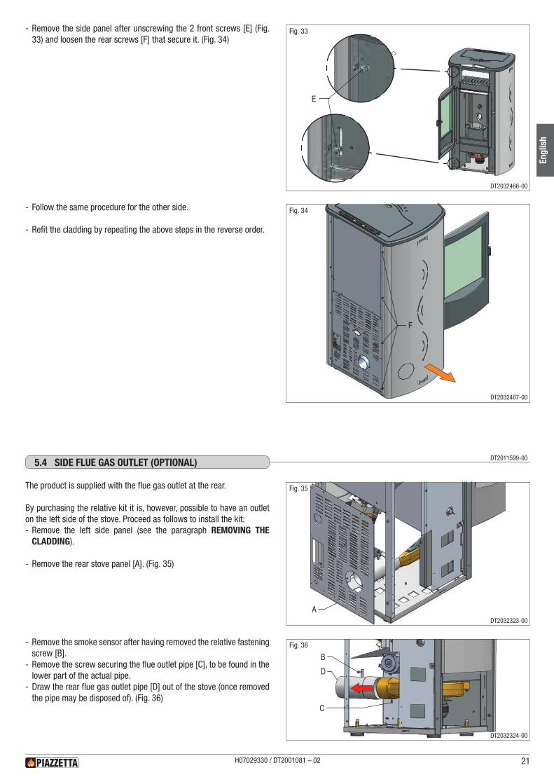
- Remove the side panel after unscrewing the 2 front screws [E] (Fig. 33) and loosen the rear screws [F] that secure it. (Fig. 34)
- Follow the same procedure for the other side.
- Refit the cladding by repeating the above steps in the reverse order.
E
F
Fig. 33
Fig. 34
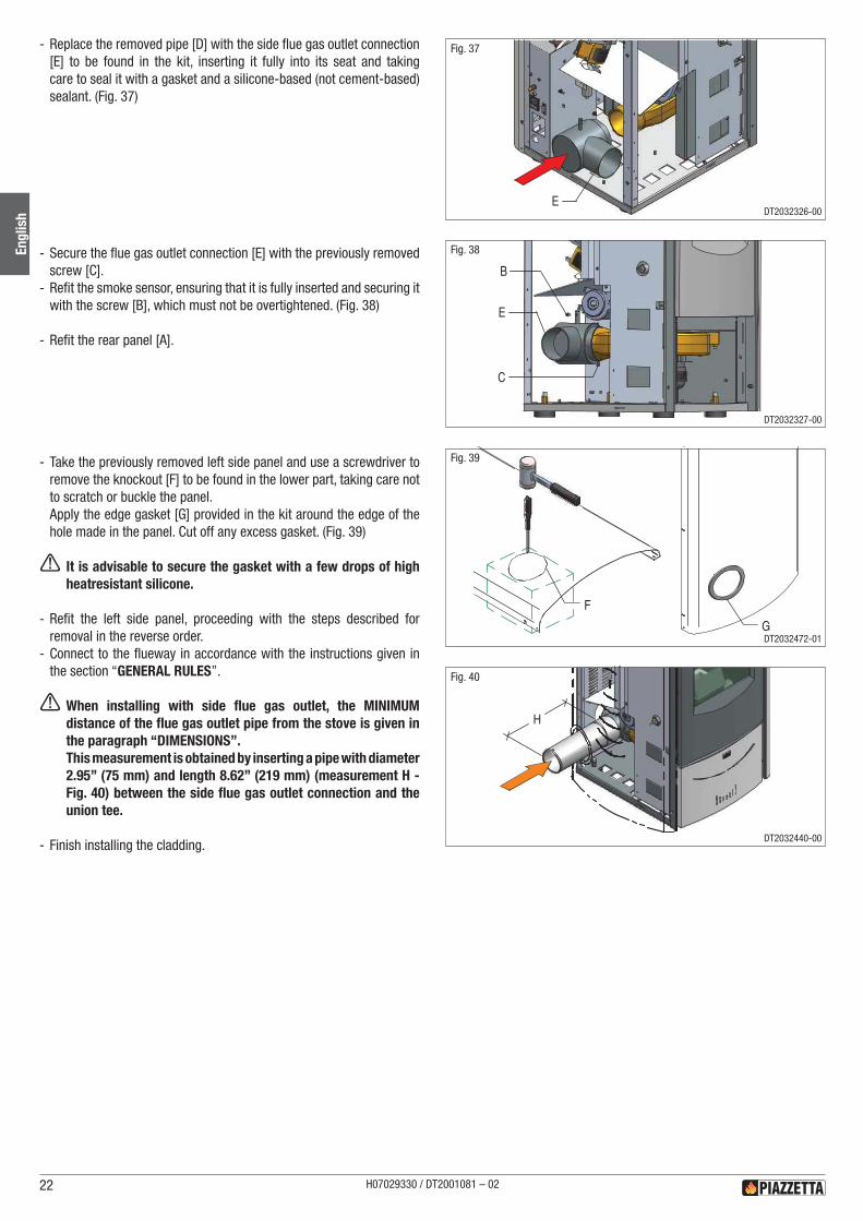
The product is supplied with the flue gas outlet at the rear.
By purchasing the relative kit it is, however, possible to have an outlet on the left side of the stove. Proceed as follows to install the kit: - Remove the left side panel (see the paragraph REMOVING THE CLADDING).
- Remove the rear stove panel [A]. (Fig. 35)
- Remove the smoke sensor after having removed the relative fastening screw [B].
- Remove the screw securing the flue outlet pipe [C], to be found in the lower part of the actual pipe.
- Draw the rear flue gas outlet pipe [D] out of the stove (once removed the pipe may be disposed of). (Fig. 36)
DT2011599-005.4 SIdE FLUE GAS OUTLET (OPTIONAL)
A
D
B
C
Fig. 35
Fig. 36
H07029330 / DT2001081 – 02 21
Engl
ish
DT2032466-00
DT2032467-00
DT2032323-00
DT2032324-00
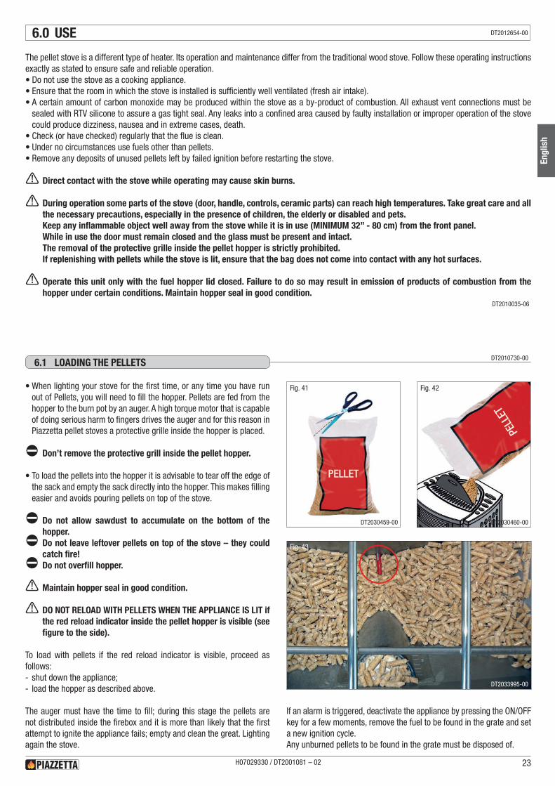
- Replace the removed pipe [D] with the side flue gas outlet connection [E] to be found in the kit, inserting it fully into its seat and taking care to seal it with a gasket and a silicone-based (not cement-based) sealant. (Fig. 37)
- Secure the flue gas outlet connection [E] with the previously removed screw [C].
- Refit the smoke sensor, ensuring that it is fully inserted and securing it with the screw [B], which must not be overtightened. (Fig. 38)
- Refit the rear panel [A].
- Take the previously removed left side panel and use a screwdriver to remove the knockout [F] to be found in the lower part, taking care not to scratch or buckle the panel.Apply the edge gasket [G] provided in the kit around the edge of the hole made in the panel. Cut off any excess gasket. (Fig. 39)
a It is advisable to secure the gasket with a few drops of high heatresistant silicone.
- Refit the left side panel, proceeding with the steps described for removal in the reverse order.
- Connect to the flueway in accordance with the instructions given in the section “GENERAL RULES”.
a When installing with side flue gas outlet, the MINIMUM distance of the flue gas outlet pipe from the stove is given in the paragraph “DIMENSIONS”.This measurement is obtained by inserting a pipe with diameter 2.95” (75 mm) and length 8.62” (219 mm) (measurement H - Fig. 40) between the side flue gas outlet connection and the union tee.
- Finish installing the cladding.
E
E
B
C
G
F
H
Fig. 37
Fig. 38
Fig. 39
Fig. 40
H07029330 / DT2001081 – 0222
Engl
ish DT2032326-00
DT2032327-00
DT2032472-01
DT2032440-00
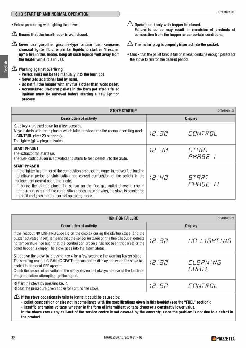
6.0 USE
The pellet stove is a different type of heater. Its operation and maintenance differ from the traditional wood stove. Follow these operating instructions exactly as stated to ensure safe and reliable operation.•Do not use the stove as a cooking appliance.•Ensure that the room in which the stove is installed is sufficiently well ventilated (fresh air intake).•A certain amount of carbon monoxide may be produced within the stove as a by-product of combustion. All exhaust vent connections must be
sealed with RTV silicone to assure a gas tight seal. Any leaks into a confined area caused by faulty installation or improper operation of the stove could produce dizziness, nausea and in extreme cases, death.
•Check (or have checked) regularly that the flue is clean.•Under no circumstances use fuels other than pellets.•Remove any deposits of unused pellets left by failed ignition before restarting the stove.
a Direct contact with the stove while operating may cause skin burns.
a During operation some parts of the stove (door, handle, controls, ceramic parts) can reach high temperatures. Take great care and all the necessary precautions, especially in the presence of children, the elderly or disabled and pets.Keep any inflammable object well away from the stove while it is in use (MINIMUM 32” - 80 cm) from the front panel.While in use the door must remain closed and the glass must be present and intact.The removal of the protective grille inside the pellet hopper is strictly prohibited.If replenishing with pellets while the stove is lit, ensure that the bag does not come into contact with any hot surfaces.
a Operate this unit only with the fuel hopper lid closed. Failure to do so may result in emission of products of combustion from the hopper under certain conditions. Maintain hopper seal in good condition.
DT2010035-06
Fig. 41
DT2010730-006.1 LOAdING ThE PELLETS
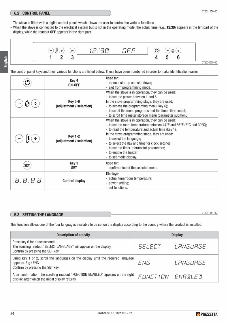
•When lighting your stove for the first time, or any time you have run out of Pellets, you will need to fill the hopper. Pellets are fed from the hopper to the burn pot by an auger. A high torque motor that is capable of doing serious harm to fingers drives the auger and for this reason in Piazzetta pellet stoves a protective grille inside the hopper is placed.
d Don’t remove the protective grill inside the pellet hopper.
•To load the pellets into the hopper it is advisable to tear off the edge of the sack and empty the sack directly into the hopper. This makes filling easier and avoids pouring pellets on top of the stove.
d Do not allow sawdust to accumulate on the bottom of the hopper. d Do not leave leftover pellets on top of the stove – they could catch fire! d Do not overfill hopper.
a Maintain hopper seal in good condition.
a DO NOT RELOAD WITH PELLETS WHEN THE APPLIANCE IS LIT if the red reload indicator inside the pellet hopper is visible (see figure to the side).
To load with pellets if the red reload indicator is visible, proceed as follows: - shut down the appliance; - load the hopper as described above.
The auger must have the time to fill; during this stage the pellets are not distributed inside the firebox and it is more than likely that the first attempt to ignite the appliance fails; empty and clean the great. Lighting again the stove.
Fig. 42
Fig. 43
If an alarm is triggered, deactivate the appliance by pressing the ON/OFF key for a few moments, remove the fuel to be found in the grate and set a new ignition cycle.Any unburned pellets to be found in the grate must be disposed of.
H07029330 / DT2001081 – 02 23
Engl
ish
DT2012654-00
DT2030459-00 DT2030460-00
DT2033995-00
DT2011650-006.2 CONTROL PANEL
- The stove is fitted with a digital control panel, which allows the user to control the various functions. - When the stove is connected to the electrical system but is not in the operating mode, the actual time (e.g.: 12:30) appears in the left part of the display, while the readout OFF appears in the right part.
The control panel keys and their various functions are listed below. These have been numbered in order to make identification easier.
.8:8:8.8
Key 4ON-OFF
Used for: - manual startup and shutdown; - exit from programming mode.
.8:8:8.8
Key 5-6(adjustment / selection)
When the stove is in operation, they can be used: - to set the power between 1 and 5.
In the stove programming stage, they are used: - to access the programming menu (key 6); - to scroll the menu programs and the timer-thermostat; - to scroll time meter storage menu (parameter submenu)
.8:8:8.8
Key 1-2(adjustment / selection)
When the stove is in operation, they can be used: - to set the room temperature between 44°F and 86°F (7°C and 30°C); - to read the temperature and actual time (key 1).
In the stove programming stage, they are used: - to select the language; - to select the day and time for clock settings; - to set the timer-thermostat parameters; - to enable the buzzer; - to set mode display.
.8:8:8.8
Key 3SET
Used for: - confirmation of the selected menu.
.8:8:8.8 Control display
Displays: - actual time/room temperature; - power setting; - set functions.
1 2 3 4 5 612:30 off
DT2011651-006.3 SETTING ThE LANGUAGE
Description of activity Display
Press key 6 for a few seconds.The scrolling readout “SELECT LANGUAGE” will appear on the display.Confirm by pressing the SET key.
SELECT LANGUAGE
Using key 1 or 2, scroll the languages on the display until the required language appears. E.g.: ENGConfirm by pressing the SET key.
ENG LANGUAGE
After confirmation, the scrolling readout “FUNCTION ENABLED” appears on the right display, after which the initial display returns. FUNCTION ENABLED
This function allows one of the four languages available to be set on the display according to the country where the product is installed.
H07029330 / DT2001081 – 0224
Engl
ish
DT2034005-00
DT2011652-006.4 PROGRAMMING
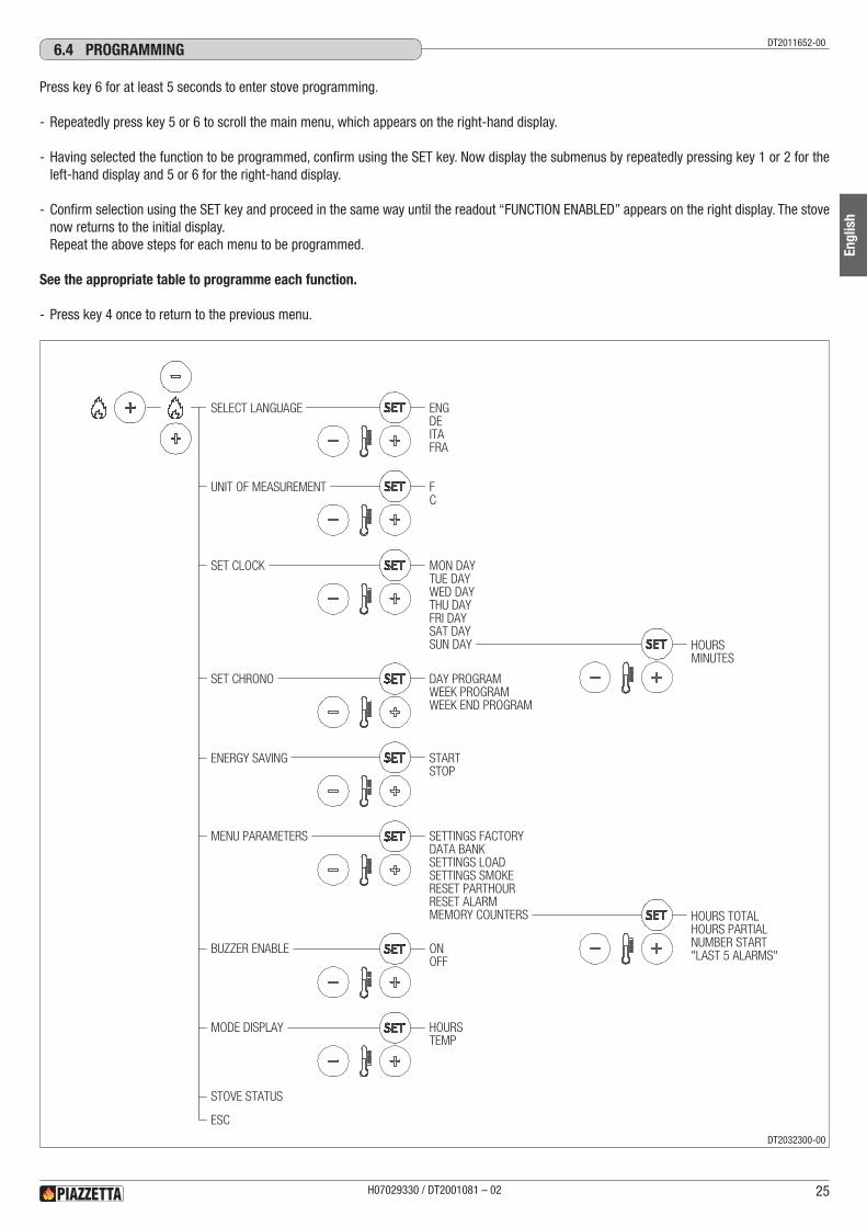
Press key 6 for at least 5 seconds to enter stove programming.
- Repeatedly press key 5 or 6 to scroll the main menu, which appears on the right-hand display.
- Having selected the function to be programmed, confirm using the SET key. Now display the submenus by repeatedly pressing key 1 or 2 for the left-hand display and 5 or 6 for the right-hand display.
- Confirm selection using the SET key and proceed in the same way until the readout “FUNCTION ENABLED” appears on the right display. The stove now returns to the initial display.Repeat the above steps for each menu to be programmed.
See the appropriate table to programme each function.
- Press key 4 once to return to the previous menu.
STOVE STATUS
ESC
ENGDEITAFRA
SELECT LANGUAGE
FC
UNIT OF MEASUREMENT
SET CHRONO DAY PROGRAMWEEK PROGRAMWEEK END PROGRAM
STARTSTOP
ENERGY SAVING
BUZZER ENABLE ONOFF
MODE DISPLAY HOURSTEMP
SET CLOCK
HOURSMINUTES
MON DAYTUE DAYWED DAYTHU DAYFRI DAYSAT DAYSUN DAY
MENU PARAMETERS SETTINGS FACTORYDATA BANKSETTINGS LOADSETTINGS SMOKERESET PARTHOURRESET ALARMMEMORY COUNTERS HOURS TOTAL
HOURS PARTIALNUMBER START"LAST 5 ALARMS"
H07029330 / DT2001081 – 02 25
Engl
ish
DT2032300-00
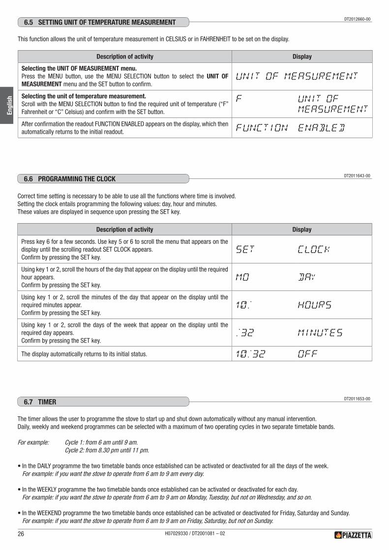
DT2012660-006.5 SETTING UNIT OF TEMPERATURE MEASUREMENT
Description of activity Display
Selecting the UNIT OF MEASUREMENT menu.Press the MENU button, use the MENU SELECTION button to select the UNIT OF MEASUREMENT menu and the SET button to confirm.
UNIT OF MEASUREMENT
Selecting the unit of temperature measurement.Scroll with the MENU SELECTION button to find the required unit of temperature (“F” Fahrenheit or “C” Celsius) and confirm with the SET button.
F UNIT OF
MEASUREMENT
After confirmation the readout FUNCTION ENABLED appears on the display, which then automatically returns to the initial readout. FUNCTION ENABLED
This function allows the unit of temperature measurement in CELSIUS or in FAHRENHEIT to be set on the display.
Description of activity Display
Press key 6 for a few seconds. Use key 5 or 6 to scroll the menu that appears on the display until the scrolling readout SET CLOCK appears.Confirm by pressing the SET key.
SET CLOCK
Using key 1 or 2, scroll the hours of the day that appear on the display until the required hour appears.Confirm by pressing the SET key.
MO DAY
Using key 1 or 2, scroll the minutes of the day that appear on the display until the required minutes appear.Confirm by pressing the SET key.
10: HOURS
Using key 1 or 2, scroll the days of the week that appear on the display until the required day appears.Confirm by pressing the SET key.
:32 MINUTES
The display automatically returns to its initial status. 10:32 oFF
DT2011643-006.6 PROGRAMMING ThE CLOCk
Correct time setting is necessary to be able to use all the functions where time is involved.Setting the clock entails programming the following values: day, hour and minutes.These values are displayed in sequence upon pressing the SET key.
DT2011653-006.7 TIMER
The timer allows the user to programme the stove to start up and shut down automatically without any manual intervention.Daily, weekly and weekend programmes can be selected with a maximum of two operating cycles in two separate timetable bands.
For example: Cycle 1: from 6 am until 9 am. Cycle 2: from 8.30 pm until 11 pm.
•In the DAILY programme the two timetable bands once established can be activated or deactivated for all the days of the week.For example: if you want the stove to operate from 6 am to 9 am every day.
•In the WEEKLY programme the two timetable bands once established can be activated or deactivated for each day.For example: if you want the stove to operate from 6 am to 9 am on Monday, Tuesday, but not on Wednesday, and so on.
•In the WEEKEND programme the two timetable bands once established can be activated or deactivated for Friday, Saturday and Sunday.For example: if you want the stove to operate from 6 am to 9 am on Friday, Saturday, but not on Sunday.
H07029330 / DT2001081 – 0226
Engl
ish
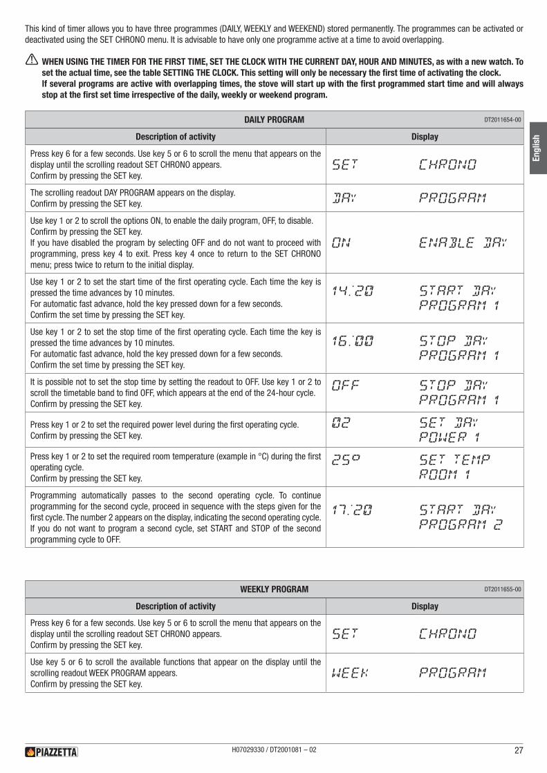
This kind of timer allows you to have three programmes (DAILY, WEEKLY and WEEKEND) stored permanently. The programmes can be activated or deactivated using the SET CHRONO menu. It is advisable to have only one programme active at a time to avoid overlapping.
a WHEN USING THE TIMER FOR THE FIRST TIME, SET THE CLOCK WITH THE CURRENT DAY, HOUR AND MINUTES, as with a new watch. To set the actual time, see the table SETTING THE CLOCK. This setting will only be necessary the first time of activating the clock.If several programs are active with overlapping times, the stove will start up with the first programmed start time and will always stop at the first set time irrespective of the daily, weekly or weekend program.
Description of activity Display
Press key 6 for a few seconds. Use key 5 or 6 to scroll the menu that appears on the display until the scrolling readout SET CHRONO appears.Confirm by pressing the SET key.
SET CHRONO
The scrolling readout DAY PROGRAM appears on the display.Confirm by pressing the SET key. DAY PROGRAM
Use key 1 or 2 to scroll the options ON, to enable the daily program, OFF, to disable.Confirm by pressing the SET key.If you have disabled the program by selecting OFF and do not want to proceed with programming, press key 4 to exit. Press key 4 once to return to the SET CHRONO menu; press twice to return to the initial display.
on ENABLE DAY
Use key 1 or 2 to set the start time of the first operating cycle. Each time the key is pressed the time advances by 10 minutes.For automatic fast advance, hold the key pressed down for a few seconds.Confirm the set time by pressing the SET key.
14:20 START DAY
PROGRAM 1
Use key 1 or 2 to set the stop time of the first operating cycle. Each time the key is pressed the time advances by 10 minutes.For automatic fast advance, hold the key pressed down for a few seconds.Confirm the set time by pressing the SET key.
16:00 STOP DAY
PROGRAM 1
It is possible not to set the stop time by setting the readout to OFF. Use key 1 or 2 to scroll the timetable band to find OFF, which appears at the end of the 24-hour cycle.Confirm by pressing the SET key.
oFF STOP DAY
PROGRAM 1
Press key 1 or 2 to set the required power level during the first operating cycle.Confirm by pressing the SET key.
02 SET DAY
POWER 1
Press key 1 or 2 to set the required room temperature (example in °C) during the first operating cycle.Confirm by pressing the SET key.
25° SET TEMP
ROOM 1
Programming automatically passes to the second operating cycle. To continue programming for the second cycle, proceed in sequence with the steps given for the first cycle. The number 2 appears on the display, indicating the second operating cycle. If you do not want to program a second cycle, set START and STOP of the second programming cycle to OFF.
17:20 START DAY
PROGRAM 2
DAILY PROGRAM DT2011654-00
Description of activity Display
Press key 6 for a few seconds. Use key 5 or 6 to scroll the menu that appears on the display until the scrolling readout SET CHRONO appears.Confirm by pressing the SET key.
SET CHRONO
Use key 5 or 6 to scroll the available functions that appear on the display until the scrolling readout WEEK PROGRAM appears.Confirm by pressing the SET key.
WEEK PROGRAM
WEEKLY PROGRAM DT2011655-00
H07029330 / DT2001081 – 02 27
Engl
ish
Description of activity Display
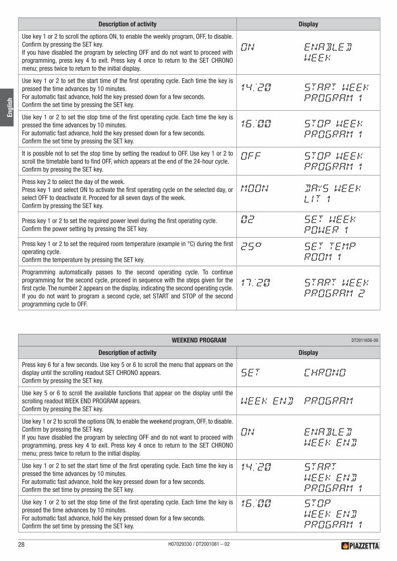
Use key 1 or 2 to scroll the options ON, to enable the weekly program, OFF, to disable.Confirm by pressing the SET key.If you have disabled the program by selecting OFF and do not want to proceed with programming, press key 4 to exit. Press key 4 once to return to the SET CHRONO menu; press twice to return to the initial display.
on ENABLED
WEEK
Use key 1 or 2 to set the start time of the first operating cycle. Each time the key is pressed the time advances by 10 minutes.For automatic fast advance, hold the key pressed down for a few seconds.Confirm the set time by pressing the SET key.
14:20 START WEEK
PROGRAM 1
Use key 1 or 2 to set the stop time of the first operating cycle. Each time the key is pressed the time advances by 10 minutes.For automatic fast advance, hold the key pressed down for a few seconds.Confirm the set time by pressing the SET key.
16:00 STOP WEEK
PROGRAM 1
It is possible not to set the stop time by setting the readout to OFF. Use key 1 or 2 to scroll the timetable band to find OFF, which appears at the end of the 24-hour cycle.Confirm by pressing the SET key.
oFF STOP WEEK
PROGRAM 1
Press key 2 to select the day of the week.Press key 1 and select ON to activate the first operating cycle on the selected day, or select OFF to deactivate it. Proceed for all seven days of the week.Confirm by pressing the SET key.
MOON DAYS WEEK
LIT 1
Press key 1 or 2 to set the required power level during the first operating cycle.Confirm the power setting by pressing the SET key.
02 SET WEEK
POWER 1
Press key 1 or 2 to set the required room temperature (example in °C) during the first operating cycle.Confirm the temperature by pressing the SET key.
25° SET TEMP
ROOM 1
Programming automatically passes to the second operating cycle. To continue programming for the second cycle, proceed in sequence with the steps given for the first cycle. The number 2 appears on the display, indicating the second operating cycle. If you do not want to program a second cycle, set START and STOP of the second programming cycle to OFF.
17:20 START WEEK
PROGRAM 2
Description of activity Display
Press key 6 for a few seconds. Use key 5 or 6 to scroll the menu that appears on the display until the scrolling readout SET CHRONO appears.Confirm by pressing the SET key.
SET CHRONO
Use key 5 or 6 to scroll the available functions that appear on the display until the scrolling readout WEEK END PROGRAM appears.Confirm by pressing the SET key.
WEEK END PROGRAM
Use key 1 or 2 to scroll the options ON, to enable the weekend program, OFF, to disable.Confirm by pressing the SET key.If you have disabled the program by selecting OFF and do not want to proceed with programming, press key 4 to exit. Press key 4 once to return to the SET CHRONO menu; press twice to return to the initial display.
on ENABLED
WEEK END
Use key 1 or 2 to set the start time of the first operating cycle. Each time the key is pressed the time advances by 10 minutes.For automatic fast advance, hold the key pressed down for a few seconds.Confirm the set time by pressing the SET key.
14:20 START
WEEK END
PROGRAM 1
Use key 1 or 2 to set the stop time of the first operating cycle. Each time the key is pressed the time advances by 10 minutes.For automatic fast advance, hold the key pressed down for a few seconds.Confirm the set time by pressing the SET key.
16:00 STOP
WEEK END
PROGRAM 1
WEEKEND PROGRAM DT2011656-00
H07029330 / DT2001081 – 0228
Engl
ish
Description of activity Display
It is possible not to set the stop time by setting the readout to OFF. Use key 1 or 2 to scroll the timetable band to find OFF, which appears at the end of the 24-hour cycle.Confirm by pressing the SET key.
oFF STOP
WEEK END
PROGRAM 1
Press key 2 to select the day of the week. Press key 1 and select ON to activate the first operating cycle on the selected day, or select OFF to deactivate it.Proceed for the three days of the week – Friday, Saturday and Sunday.Confirm by pressing the SET key.
SUON DAYS WEEK END
LIT 1
Press key 1 or 2 to set the required power level during the first operating cycle.Confirm the power setting by pressing the SET key.
02 SET WEEK END
POWER 1
Press key 1 or 2 to set the required room temperature (example in °C) during the first operating cycle.Confirm the temperature by pressing the SET key.
25° SET TEMP
ROOM 1
Programming automatically passes to the second operating cycle. To continue programming for the second cycle, proceed in sequence with the steps given for the first cycle. The number 2 appears on the display, indicating the second operating cycle. If you do not want to program a second cycle, set START and STOP of the second programming cycle to OFF.
17:20 START
WEEK END
PROGRAM 2
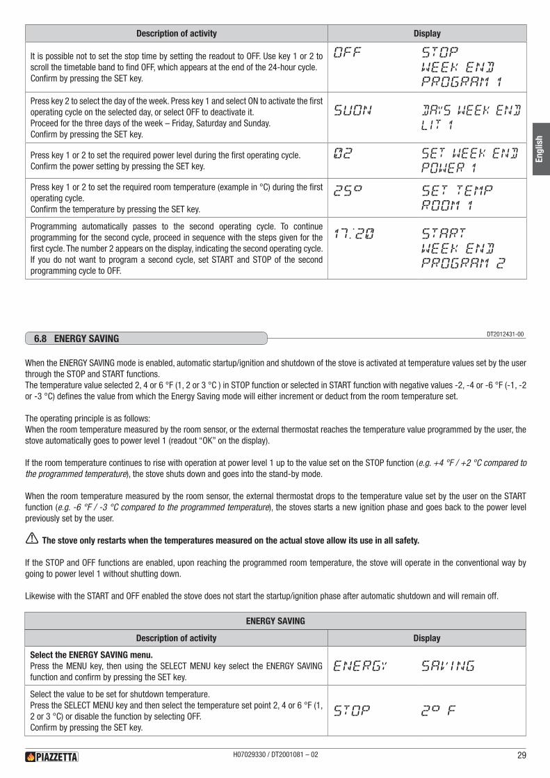
DT2012431-006.8 ENERGy SAvING
When the ENERGY SAVING mode is enabled, automatic startup/ignition and shutdown of the stove is activated at temperature values set by the user through the STOP and START functions.The temperature value selected 2, 4 or 6 °F (1, 2 or 3 °C ) in STOP function or selected in START function with negative values -2, -4 or -6 °F (-1, -2 or -3 °C) defines the value from which the Energy Saving mode will either increment or deduct from the room temperature set.
The operating principle is as follows:When the room temperature measured by the room sensor, or the external thermostat reaches the temperature value programmed by the user, the stove automatically goes to power level 1 (readout “OK” on the display).
If the room temperature continues to rise with operation at power level 1 up to the value set on the STOP function (e.g. +4 °F / +2 °C compared to the programmed temperature), the stove shuts down and goes into the stand-by mode.
When the room temperature measured by the room sensor, the external thermostat drops to the temperature value set by the user on the START function (e.g. -6 °F / -3 °C compared to the programmed temperature), the stoves starts a new ignition phase and goes back to the power level previously set by the user.
a The stove only restarts when the temperatures measured on the actual stove allow its use in all safety.
If the STOP and OFF functions are enabled, upon reaching the programmed room temperature, the stove will operate in the conventional way by going to power level 1 without shutting down.
Likewise with the START and OFF enabled the stove does not start the startup/ignition phase after automatic shutdown and will remain off.
Description of activity Display
Select the ENERGY SAVING menu.Press the MENU key, then using the SELECT MENU key select the ENERGY SAVING function and confirm by pressing the SET key.
ENERGY SAVING
Select the value to be set for shutdown temperature.Press the SELECT MENU key and then select the temperature set point 2, 4 or 6 °F (1, 2 or 3 °C) or disable the function by selecting OFF.Confirm by pressing the SET key.
STOP 2° F
ENERGY SAVING
H07029330 / DT2001081 – 02 29
Engl
ish
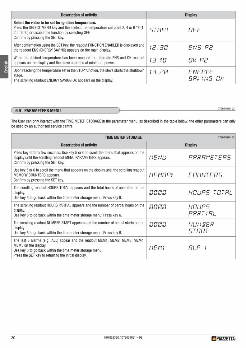
Description of activity Display
Select the value to be set for ignition temperature.Press the SELECT MENU key and then select the temperature set point 2, 4 or 6 °F (1, 2 or 3 °C) or disable the function by selecting OFF.Confirm by pressing the SET key.
START OFF
After confirmation using the SET key, the readout FUNCTION ENABLED is displayed and the readout ENS (ENERGY SAVING) appears on the main display. 12:30 ENS P2
When the desired temperature has been reached the alternate ENS and OK readout appears on the display and the stove operates at minimum power. 13:10 OK P2
Upon reaching the temperature set in the STOP function, the stove starts the shutdown stage.The scrolling readout ENERGY SAVING OK appears on the display.
13:20 ENERGY
SAVING OK
DT2011676-006.9 PARAMETERS MENU
The User can only interact with the TIME METER STORAGE in the parameter menu, as described in the table below: the other parameters can only be used by an authorised service centre.
Description of activity Display
Press key 6 for a few seconds. Use key 5 or 6 to scroll the menu that appears on the display until the scrolling readout MENU PARAMETERS appears.Confirm by pressing the SET key.
MENU PARAMETERS
Use key 5 or 6 to scroll the menu that appears on the display until the scrolling readout MEMORY COUNTERS appears.Confirm by pressing the SET key.
MEMORY COUNTERS
The scrolling readout HOURS TOTAL appears and the total hours of operation on the display.Use key 5 to go back within the time meter storage menu. Press key 6.
0000 HOURS TOTAL
The scrolling readout HOURS PARTIAL appears and the number of partial hours on the display.Use key 5 to go back within the time meter storage menu. Press key 6.
0000 HOURS
PARTIAL
The scrolling readout NUMBER START appears and the number of actual starts on the display.Use key 5 to go back within the time meter storage menu. Press key 6.
0000 NUMBER
START
The last 5 alarms (e.g.: ALL) appear and the readout MEM1, MEM2, MEM3, MEM4, MEM5 on the display.Use key 5 to go back within the time meter storage menu.Press the SET key to return to the initial display.
MEM1 ALF 1
TIME METER STORAGE DT2011679-00
H07029330 / DT2001081 – 0230
Engl
ish
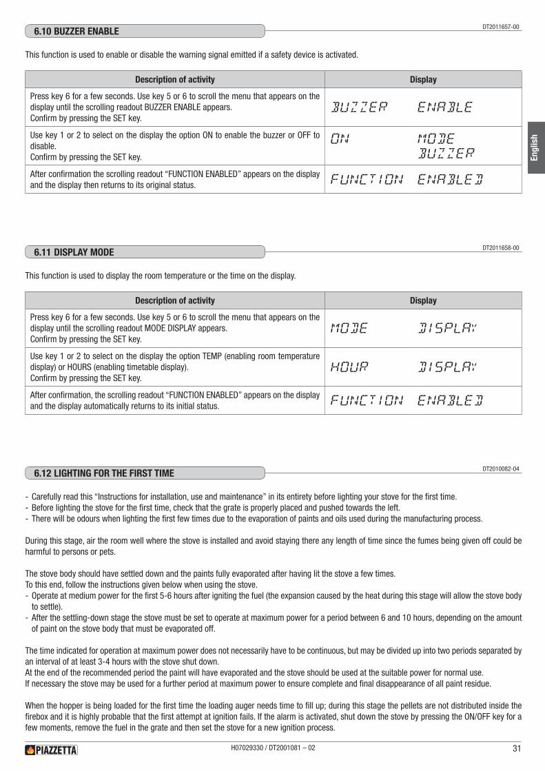
DT2011657-006.10 bUzzER ENAbLE
DT2011658-006.11 dISPLAy MOdE
This function is used to enable or disable the warning signal emitted if a safety device is activated.
This function is used to display the room temperature or the time on the display.
Description of activity Display
Press key 6 for a few seconds. Use key 5 or 6 to scroll the menu that appears on the display until the scrolling readout BUZZER ENABLE appears.Confirm by pressing the SET key.
BUZZER ENABLE
Use key 1 or 2 to select on the display the option ON to enable the buzzer or OFF to disable.Confirm by pressing the SET key.
ON MODE
BUZZER
After confirmation the scrolling readout “FUNCTION ENABLED” appears on the display and the display then returns to its original status. FUNCTION ENABLED
Description of activity Display
Press key 6 for a few seconds. Use key 5 or 6 to scroll the menu that appears on the display until the scrolling readout MODE DISPLAY appears.Confirm by pressing the SET key.
MODE DISPLAY
Use key 1 or 2 to select on the display the option TEMP (enabling room temperature display) or HOURS (enabling timetable display).Confirm by pressing the SET key.
HOUR DISPLAY
After confirmation, the scrolling readout “FUNCTION ENABLED” appears on the display and the display automatically returns to its initial status. FUNCTION ENABLED
DT2010082-046.12 LIGhTING FOR ThE FIRST TIME
- Carefully read this “Instructions for installation, use and maintenance” in its entirety before lighting your stove for the first time. - Before lighting the stove for the first time, check that the grate is properly placed and pushed towards the left. - There will be odours when lighting the first few times due to the evaporation of paints and oils used during the manufacturing process.
During this stage, air the room well where the stove is installed and avoid staying there any length of time since the fumes being given off could be harmful to persons or pets.
The stove body should have settled down and the paints fully evaporated after having lit the stove a few times.To this end, follow the instructions given below when using the stove. - Operate at medium power for the first 5-6 hours after igniting the fuel (the expansion caused by the heat during this stage will allow the stove body to settle).
- After the settling-down stage the stove must be set to operate at maximum power for a period between 6 and 10 hours, depending on the amount of paint on the stove body that must be evaporated off.
The time indicated for operation at maximum power does not necessarily have to be continuous, but may be divided up into two periods separated by an interval of at least 3-4 hours with the stove shut down.At the end of the recommended period the paint will have evaporated and the stove should be used at the suitable power for normal use.If necessary the stove may be used for a further period at maximum power to ensure complete and final disappearance of all paint residue.
When the hopper is being loaded for the first time the loading auger needs time to fill up; during this stage the pellets are not distributed inside the firebox and it is highly probable that the first attempt at ignition fails. If the alarm is activated, shut down the stove by pressing the ON/OFF key for a few moments, remove the fuel in the grate and then set the stove for a new ignition process.
H07029330 / DT2001081 – 02 31
Engl
ish
DT2011659-006.13 START UP ANd NORMAL OPERATION
•Before proceeding with lighting the stove:
a Ensure that the hearth door is well closed.
a Never use gasoline, gasoline-type lantern fuel, kerosene, charcoal lighter fluid, or similar liquids to start or ”freschen up” a fire in this heater. Keep all such liquids well away from the heater wihle it is in use.
a Warning against overfiring: - Pellets must not be fed manually into the burn pot. - Never add additional fuel by hand. - Do not fill the hopper with any fuels other than wood pellet. - Accumulated un-burnt pellets in the burn pot after a failed ignition must be removed before starting a new ignition process.
Description of activity Display
Keep key 4 pressed down for a few seconds.A cycle starts with three phases which take the stove into the normal operating mode. - CONTROL (first 20 seconds).
The lighter (glow plug) activates.
12:30 CONTROL
START PHASE IThe extractor fan starts up.The fuel-loading auger is activated and starts to feed pellets into the grate.
12:30 START
PHASE I
START PHASE II - If the lighter has triggered the combustion process, the auger increases fuel loading to allow a period of stabilisation and correct combustion of the pellets in the subsequent normal operating mode.
- If during the startup phase the sensor on the flue gas outlet shows a rise in temperature (sign that the combustion process is underway), the stove is considered to be lit and goes into the normal operating mode.
12:40 START
PHASE II
Description of activity Display
If the readout NO LIGHTING appears on the display during the startup stage (and the buzzer activates, if set), it means that the sensor installed on the flue gas outlet detects no temperature rise (sign that the combustion process has not been triggered) or the pellet hopper is empty. The stove goes into the alarm status.
12:30 NO LIGHTING
Shut down the stove by pressing key 4 for a few seconds: the warning buzzer stops.The scrolling readout CLEANING GRATE appears on the display and when the stove has cooled the readout OFF appears.Check the causes of activation of the safety device and always remove all the fuel from the grate before attempting ignition again.
12:30 CLEANING
GRATE
Restart the stove by pressing key 4.Repeat the procedure given above for lighting the stove. 12:50 CONTROL
a If the stove occasionally fails to ignite it could be caused by: - pellet composition or size not in compliance with the specifications given in this booklet (see the “FUEL” section); - insufficient mains voltage, whether in the form of intermittent voltage drops or a constantly lower value.
In the above cases any call-out of the service centre is not covered by the warranty, since the problem is not due to a defect in the product.
STOVE STARTUP DT2011660-00
IGNITION FAILURE DT2011661-00
a Operate unit only with hopper lid closed.Failure to do so may result in emmision of products of combustion from the hopper under certain conditions.
a The mains plug is properly inserted into the socket.
•Check that the pellet tank is full or at least contains enough pellets for the stove to run for the desired period.
H07029330 / DT2001081 – 0232
Engl
ish
Description of activity Display
The user attempts to restart the stove during the shutdown stage when the stove is still hot by pressing the ON/OFF key for a few moments.If the readout “WAIT FOR START UP” appears on the display by pressing the ON/OFF key for a few moments, it means that the stove is still hot and it is necessary to wait for it to cool.The new ignition cycle will be inhibited until the stove ends the cooling phase.After waiting for a few minutes the user can restart the stove and a new ignition cycle will start automatically from the control stage.
WAIT FOR START UP
WAIT FOR START UP DT2040123-00
Description of activity Display
Once the stove is properly lit, it will stabilise in the normal mode of operation.The power setting appears on the display: P1, P2, P3, P4, P5.The time or the room temperature appears on the display. (See paragraph “DISPLAY MODE”).The power and the room temperature settings may be adjusted during normal operation.
12:50 P2
POWERTo change the power setting, press key 6.The scrolling readout SET POWER appears on the display.Use key 5 or 6 to select the required power level, which will appear on the display.The display automatically returns to its initial status.
P2 SET POWER
ROOM TEMPERATURETo change the temperature setting, press the SET key. The scrolling readout SET ROOM TEMP appears on the display.Use key 1 or 2 to select the required temperature from a scale between 44°F and 86°F (7°C and 30°C), which will appear in the left display.The display automatically returns to its initial status.
25° SET ROOM
TEMP
When the desired temperature has been reached the readout OK appears in the initial display and the stove operates at minimum power even if the display shows the originally set power level. The temperature can be read by the stove or by an external thermostat. To choose whether the stove or the external thermostat will read the temperature see the paragraph “EXTERNAL THERMOSTAT”.If using an external thermostat the readout “TON” appears in the display and the readings from the stove are cut out.
14:15 OK P2
Automatic grate cleaning is activated during regular stove operation at programmed intervals that are set by Superior personnel. This procedure is necessary in order to eliminate accumulation of ash or encrustation that would prevent correct stove operation and must therefore be removed.
16:30 CLEANING
GRATE
If the temperature rises above a fixed value during normal stove operation at maximum power, the fan motor operates at maximum speed and the stove runs at reduced heat input for a few minutes to help disperse the heat and prevent the appliance from possibly overheating.
16:50 MAX VENT
FLUE COOL
NORMAL OPERATION DT2011662-00
H07029330 / DT2001081 – 02 33
Engl
ish
Description of activity Display
Stove operation can be regulated by any kind of external room thermostat connected to the electronic board.To connect the thermostat, see paragraph “INSTALLING THE EXTERNAL ROOM THERMOSTAT”.
Operation of the external thermostat depends on the stove temperature setting. - If the set stove temperature is less than the room temperature, the external thermostat prevails. (It is advisable to set a minimum value of 44°F (7°C) for the stove).
- If the set stove temperature is more than the room temperature, the internal stove thermostat prevails. The external thermostat is disabled.
The readout TON appears in the display.
a The room sensor must be connected. If the room sensor is not connected the appliance does not change the power and operates to user settings.
EXTERNAL THERMOSTAT DT2011663-00
Description of activity Display
If there is a blackout while the stove is in operation, there are two possibilities of procedure according to stove set-up: - blackout without timer thermostat settings; - blackout with timer thermostat settings.
Blackout without timer thermostat settings.When the electricity supply is restored, the appliance restarts automatically.•The grate cleaning phase activates.•The fan operates at full speed to allow the stove to cool.•The automatic stove restart cycle starts (the steps detailed in the ‘STARTUP’ phase
are repeated automatically).•Once the ignition cycle has been completed the stove operates normally at power
level 2.
Blackout with timer thermostat settings.There are 3 possible situations.•Blackout straddling the time set for ignition: the stove does not restart.•Blackout straddling the time set for shutdown: the stove restarts when the electricity
supply is restored.•Blackout within the programmed operating time band: the stove restarts when the
electricity supply is restored.
Restarting is carried out with the same procedure as listed in “Blackout without timer thermostat settings”.
16:30 CLEANING
POWER SUPPLY CUTOFF DT2011665-01
Description of activity Display
Hold the ON/OFF key down for several seconds.Fuel loading stops, while the cooling fan and the extractor fan continue to operate until the stove is cool.The scrolling readout CLEANING GRATE first appears followed by the readout OFF.If the ENERGY SAVING MODE has been activated, the readout OFF is followed by ENS to remember that energy saving mode is enabled.
a Never unplug the stove from the power supply at this stage as this could cause internal problems and jeopardise subsequent ignition operations.
CLEANING GRATE
SHUTDOWN DT2011664-00
H07029330 / DT2001081 – 0234
Engl
ish
+ +- -
DT2011646-006.14 REMOTE CONTROL (OPTIONAL)
Fig. 44 On request the stove may be supplied with a remote control, which can be used to govern certain stove functions.
- Startup/Shutdown: by pressing the two + keys simultaneously the stove can be turned on or off.
- Power level: when operating normally, pressing the + and - keys above the flame symbol will select one of the four power levels of the stove.
- Temperature: when operating normally, pressing the + and - keys above the thermometer symbol will select the desired room temperature (44° F and 86° F - 7° C and 30° C).
DT2010994-006.15 SAFETy dEvICES
a During operation some parts of the stove (door, handle, ceramic parts) can reach high temperatures.
Remember to maintain the safety distances indicated previously.Be careful, take all due precautions and always comply with the instructions.If during operation smoke leaks from any part of the stove or the flue, shut the stove down immediately and ventilate the room. When the stove has cooled, check for the cause of the leak and if necessary call in specialist personnel.The stove is fitted with several safety devices to guarantee safe operation.
a The safety devices are fitted to eliminate the risk of injury to people and pets and damage to property. Tampering or work carried out by unauthorised personnel can jeopardise this function.
d IN CASE OF ANY ALARM SIGNALS DO NOT UNPLUG THE STOVE: JUST TURN THE UNIT OFF.
Possible warnings of problemsSimple operating problems can usually be resolved with the help of the following pages.
Description of activity Display
Connected to the flue gas outlet, its function is to control the vacuum inside the outlet duct so that the stove can be used in all safety.
If correct operating conditions in the flue gas outlet change (incorrect installation, blockages or obstructions in the flue, poor maintenance, unfavourable weather conditions such as persistent wind, etc.) the pressure switch cuts off the power supply to the fuel-loading auger, thereby stopping the supply of pellets to the grate and starting the stove shutdown process. - The readout “ALF 1” appears in the STOVE STATUS mode. - The readout “SAFETY SMOKE“ appears on the display. - After approx. 60 seconds the alarm sounds (if activated).
SAFETY SMOKE
WHAT TO DO: - Shut down the stove by holding the ON/OFF key down for several seconds. - The alarm stops. - Wait until you are sure that combustion of any pellets remaining in the grate has stopped.
- Wait until the stove has cooled down, then check for and remove whatever has caused the safety device to be triggered. Finally, after having cleaned the grate restart the stove by pressing the ON/OFF key.
SMOKE CHAMBER PRESSURE DT2040095-00
H07029330 / DT2001081 – 02 35
Engl
ish
DT2030079-00
Description of activity Display
Located on the pellet hopper, its function is to prevent excessive temperature ranges.
If the pellet hopper temperature reaches critical levels, the thermostat cuts off the power supply to the fuel-loading auger, thereby stopping the supply of pellets to the grate and starting the stove shutdown process. - The readout ‘ALC’ appears in the STOVE STATUS mode. - After approx. 60 seconds the alarm sounds (if activated).
TANK TEMP SAFETY
WHAT TO DO: - Shut down the stove by holding the ON/OFF key down for several seconds. - The alarm will stop. - Wait until combustion of any pellets remaining in the grate has finished. - After having cleaned the grate, restart the stove by pressing the ON/OFF key. (The readout TANK TEMP SAFETY must no longer appear on the display. If this is not the case repeat the process described above.)
Description of activity Display
Its function is to check correct operation of the flue gas fan so that the stove can be used in all safety.
If the black-red-white cable connected to the flue gas fan (see the paragraph “WIRING DIAGRAM”) momentarily or accidentally removed from its normal position, or is not connected properly to the electronic board, or the speed of the smoke fan is greater or lower than the set value according to settings smoke parameter, the readout “ALF 3” or “ALF 4” will appear in STOVE STATUS MODE. - The readout “SMOKE FAN FAILURE” appears on the display. - After approx. 60 seconds the alarm sounds (if activated).
SMOKE FAN FAILURE
WHAT TO DO: - Shut down the stove by holding the ON/OFF key down for several seconds. - The alarm stops. - Call the After-Sales Service Centre.
PELLET HOPPER HOUSING TEMPERATURE DT2010995-00
FLUE GAS FAN RUNNING DT2012666-00
Description of activity Display
Its function is to check correct operation of the pressure switch so that the stove can be used in all safety.
It activates during the “START” stage of the stove (see “STARTING THE STOVE” table).If an anomaly is detected in the pressure switch, the readout “ALF 2” appears in the STOVE STATUS mode.The readout “SAFETY SMOKE” appears on the display.After approx. 60 seconds the alarm sounds (if activated).
SAFETY SMOKE
WHAT TO DO: - Shut down the stove by holding the ON/OFF key down for several seconds. - The alarm stops. - Call the After-Sales Service Centre.
H07029330 / DT2001081 – 0236
Engl
ish
Description of activity Display
Connected to the electronic board, it constantly monitors the working temperature allowing the stove to be used in all safety.
If the temperature exceeds the fixed safety limit the board cuts off the power supply to the fuelloading auger thus depriving the grate of pellets and starting the stove shutdown process. - In the upper part of the display appears the message “SAFETY” and in the lover part appears “STOVE”.
- The readout ”MASS TEMP” and the flue gas temperature appear in the STOVE STATUS mode.
- After approx. 60 seconds the alarm sounds (if activated).
SAFETY STOVE
WHAT TO DO: - Shut down the stove by holding the ON/OFF key down for several seconds. - The alarm stops. - Wait until you are sure that combustion of any pellets remaining in the grate has stopped.
- Check for and remove whatever has triggered the safety device. - After having cleaned the grate restart the stove by pressing the ON/OFF key.
If the sensor is momentarily or accidentally removed from its normal position, or is not connected properly to the electronic board, the readout “NO CONN” will appear in the STOVE STATUS mode. - The readout “PROBE SMOKE” appears on the display. - After approx. 60 seconds the alarm sounds (if activated).
PROBE SMOKE
WHAT TO DO: - Shut down the stove by holding the ON/OFF key down for several seconds. - The alarm stops. - Call the After-Sales Service Centre.
FLUE GAS TEMPERATURE SENSOR DT2040054-00
Description of activity Display
Connected to the rear of the stove, it constantly monitors the temperature in the immediate vicinity of the stove to ensure that it can be operated in all safety.
If the sensor is momentarily or accidentally removed from its normal position, the problem does not require the immediate shutdown of the stove, which will continue to operate normally at the set power level.The problem will be indicated on the STOVE STATUS by the readout “NO CONN”.
16:25 P2
WHAT TO DO: - Put the sensor back in its proper position. - If the room temperature display has been activated, it will once again be shown.
STOVE ROOM TEMPERATURE SENSOR DT2040055-03
H07029330 / DT2001081 – 02 37
Engl
ish
DT2010248-046.16 STOvE STATUS
This function displays the stove status under the various operating conditions.
Description of activity Display
Press key 6 for a few seconds.Use key 5 or 6 to scroll the menu that appears on the display until the scrolling readout STOVE STATUS appears.Confirm by pressing the SET key.
STOVE STATUS
The pellet loading time, the flue gas temperature, the combustion fan speed and any alarms or informations appear on the display alternately.A list of readouts which can appear is given below:PUL Clean grateALF 1 Pressure switch activated Fuel hopper lid openALF 2 Anomaly in the pressure switchALF 3 Anomaly in combustion fan speed (greater than set value)ALF 4 Anomaly in combustion fan speed (lower than set value)ALC Safety thermostat activatedNO CONN Smoke sensor or ambient sensor disconnectedNO ACC Failed ignitionMASS TEMP Smoke alarm activated - maximum temperature reached.
Use key 4 to exit.
DT2010087-046.17 OPENING ThE dOOR
a During operation the door must remain closed.It is to be opened only when the stove has been shut down and cooled for the carrying out of maintenance.
Use the door handle tool provided in the kit to open the door, using it as shown in the picture below.
Fig. 45
H07029330 / DT2001081 – 0238
Engl
ish
DT2032285-00
DT2011671-006.18 hUMIdIFIER FOR STOvE
Fig. 46 The stove is provided with a niche for a humidifier (optional) located under the ceramic insert of the top plate: once the ceramic cladding has been fitted, the humidifier can be filled with water.
a When refilling the humidifier do not exceed the maximum capacity, shown as max, otherwise the electrical parts of the stove could be damaged.
DT2010049-046.19 dISPOSAL OF AShES
Ash from natural (non-treated) wood burned in stoves or open fireboxes is composed mainly of calcium, silicon, potassium and magnesium oxides. The ashes can therefore be used as a fertiliser for plants or in the garden, albeit not exceeding 2.6 kg per 10m2 annually.
a The ashes should be placed in a metal container with a sealed cover. The sealed container should be placed on a non-combustible surface at a safe distance from combustible materials until the cinders have been completely extinguished.
d Only when they have been fully extinguished can the ashes be thrown away with organic waste, assuming that nails or other non-organic material are not present.
H07029330 / DT2001081 – 02 39
Engl
ish
DT2032301-00
7.0 MAINTENANCE
Pursuant to current regulations on the safety of electrical equipment, you must contact your dealer or a qualified electrician for all and any work connected with installation, maintenance or servicing that involves access to electrical parts or internal mechanical parts.
Maintenance is to be considered compulsory for correct and efficient stove operation. If maintenance is not carried out with the recommended frequency, stove performance could suffer. The manufacturer will not be responsible for stove deterioration or malfunction if due to poor maintenance.The frequency of cleaning depends on how much the stove is used and the quality of the fuel.All maintenance work (cleaning, any replacements, etc.) must be carried out when the stove is shutdown, completely cold and the supply cable disconnected.Do not use materials that could scratch or damage the glass, since scratches could become cracks. Under no circumstances use abrasive substances.
On the following paragraphs, the reported time indications are to be considered on example.To dispose the ashes, refer to the paragraph “DISPOSAL OF ASHES”. DT2010057-02
DT2011673-007.1 CLEANING ThE GRATE ANd ThE GRATE SUPPORT
DT2010100-037.2 CLEANING ThE ASh TRAy
Clean the grate area every day and whenever the stove is to be lit: - remove the grate baffle plate and lift out the grate; - remove any ash or other material that may have built up, taking particular care to free any clogged holes using a sharp pointed tool;
- make sure the “ignition hole”, located on the rear side of the grate, is kept clean;
- check the grate support and remove any ash.
a To dispose the ashes, refer to the paragraph “DISPOSAL OF ASHES”.
a After cleaning and before lighting the stove, check that the grate is correctly inserted and pushed back towards. Refit the grate baffle plate.
GRATE BAFFLE PLATE
GRATE
Fig. 47
Every day, check the ash drawer to see if it needs emptying.
The ash content of the fuel operation of your stove will directly determine the frequency of cleaning. The use of high ash fuels may result in the stove needing to be cleaned daily.Pellets made from hardwood contain more ash than those made from softwood.
To dispose the ashes, refer to the paragraph “DISPOSAL OF ASHES”.
Fig. 48 IGNITION HOLE
Fig. 49
H07029330 / DT2001081 – 0240
Engl
ish
DT2011672-00
DT2032476-00
DT2030239-00
DT2032477-00
DT2010428-037.3 CLEANING ThE FIREbOx
BOTTOMRESTRAINT
REARBAFFLE PLATE
UPPERBAFFLE PLATE
ECCENTRICCLAMP
Fig. 50 Once a week clean the firebox as follows. - Remove the grate baffle and draw out the grate. - Turn the eccentric clamps to free the internal baffle. - Lift the baffle slightly, gripping it by the two outer tabs to free it at the bottom and then turn it, bringing the bottom outwards, and remove.
- Using a vacuum cleaner remove the ash from the firebox. - After having thoroughly cleaned the firebox, remount the internal baffle proceeding in the reverse order to above.
- Ensure that the tabs are properly inserted into the relative notches in the sides of the firebox and secure the baffle by turning the two eccentric clamps.
- Replace the grate, pushing it to the. - Replace the grate baffle plate.
a This type of cleaning requires a vacuum cleaner suitable for holding ash.
a To dispose the ashes, refer to the paragraph “DISPOSAL OF ASHES”.
DT2011674-007.4 CLEANING ThE SMOkE ChAMbER
Fig. 51
Fig. 52
Fig. 53
Once a year clean the smoke chamber as follows: - remove the screws which secure the smoke chamber cover, then lift it slightly and take it out by pulling it towards you (Fig. 51 - 52);
- use a vacuum cleaner to remove any ash and carbon deposits which can accumulate in the chamber, taking care not to damage the blades of the fan (Fig. 53);
- check the hole inside the smoke chamber on the left side (leading to the device for measuring the vacuum) for dust and ash and clean if necessary;
- after thorough cleaning, change the gasket and replace the smoke chamber closing element.
a This type of cleaning requires a vacuum cleaner suitable for holding ash.
H07029330 / DT2001081 – 02 41
Engl
ish
DT2032478-00
DT2032479-00
DT2032480-00
DT2032481-00
DT2010092-037.5 CLEANING ThE FLUE SySTEM
Fig. 54 Soot and Flyash: formation and need for removal.
The products of combustion will contain small particles of flyash. The flyash will collect in the exhaust venting system and restrict the flow of the flue gases. Incomplete combustion, such as occurs during startup, shutdown, or incorrect operation of the room heater will lead to some soot formation which will collect in the exhaust venting system. The exhaust venting system should be inspected at least once every two months during the heating season to determine if cleaning is necessary.
Until you have got reasonably used to the operating conditions of the stove, we recommend that this maintenance be carried out on a monthly basis.
Remove the plug from the Tee and clean the pipes.
Do not use a metal trush to clean this vent. Such a brush may scratch the vent liner and promote corrosion. Do not use chemical cleaners in this vent system. They do not eliminate need for manual cleaning and may be corrosive to vent materials.
If necessary, particularly on the first few occasions, we recommend calling in a qualified technician.
DT2010059-037.6 CLEANING ThE CERAMIC CLAddING
The ceramic cladding must first be cleaned with a soft dry cloth before using any detergent (even mild detergent).Products are available on the market which are suitable for cleaning ceramics as well as concentrated products for cleaning porcelain. These will remove oil, ink, coffee and wine stains, etc.
d Never soak the ceramic cladding or clean it with cold water when it is still hot as the thermal shock could cause it to crack.
DT2010061-037.7 CLEANING ThE ENAMELLEd METAL PARTS
DT2010062-057.8 CLEANING ThE GLASS (dAILy)
When cleaning the enamelled metal parts of the product use a soft cloth moistened with water
d Never clean metallic parts using alcohol, solvents, petroleum-based products, acetones or other degreasing or abrasive substances.
In the event of such substances being used, the manufacturer will not be responsible for any damage caused.Discolouration of metallic parts may be the result of misuse.
a The glass should be cleaned when cold using amSABRINA-based degreasing agents and not corrosive substances such as solvents.
Although it is likely that tar will build up on the glass during the lighting stage, it will burn off with the stove in full operation.If, however, the tar is left to build up over a long period it will require more effort to remove.We therefore recommend that the glass be cleaned daily before lighting the stove.
d Do not use any material that could scratch or spoil the glass, as scratches may develop into cracks or breaks.
H07029330 / DT2001081 – 0242
Engl
ish
DT2031151-00
DT2010093-067.9 REPLACING ThE wINdOw
The stove is fitted with a 0.197” / (5 mm) thick ceramic glass panel, resistant to thermal shock up to 1382°F / (750°C); the glass can only be broken by heavy impact or misuse.Do not slam the door or hit the window. In case of breakage replace only with a Gruppo Piazzetta spare part.To replace, proceed as follows: - wear protective gloves; - remove the door and lie it flat; - loosen the screws visible on the inside of the door; - remove the frame and glass carefully; - if the fibreglass seal and glazing bead have deteriorated, replace them; - change the glass panel then replace the frame, tightening the screws carefully but not excessively; - remount the door.
If other problems occur, consult your nearest retailer.
DT2010094-007.10 REPLACING ThE REMOTE CONTROL bATTERy
a The remote control is optional.
To change the battery proceed as follows: using a small Philips head screwdriver, remove the screw on the back of the handset. Then holding it upside down remove the back casing.Replace the battery (type A23 12V) being careful not to reverse the polarity. Close the handset and dispose of the old battery in the appropriate way.
DT2010095-067.11 CLEANING ThE FANS
DT2010096-057.12 whEN NOT IN USE
a Any cleaning or maintenance work must be carried out after the CURRENT HAS BEEN SWITCHED OFF.
The stove is fitted with fans (smoke extractor and heating) positioned at the bottom rear of the stove.Any build-up of dust or ash on the blades can unbalance them resulting in noise during operation.It is necessary to have the fans cleaned annually. Since such an operation involves dismantling certain parts of the stove, have the cleaning carried out only by authorized personnel or other qualified persons.
When shutting the stove down for the summer, proceed as follows: - remove all pellets from the hopper and feeding auger; - carefully clean the grate, the grate support and the ash drawer; - using a steel brush, clean the baffle plate or internal baffle plates of the firebox and coat them using the spray paint, supplied with the kit, to prevent them from oxidising and consequently forming rust.
a If the cast-iron parts inside the firebox are not coated, rust could form. This is a natural process, which does not affect the efficiency and quality of the product.
- Clean the flue thoroughly: contact a professional chimneysweep for this purpose; - clean by removing all dust, cobwebs, etc. from the area behind the inner lining panels once a year, in particular the fans; - disconnect the power cable from the power supply; - remove the batteries from the remote control.
H07029330 / DT2001081 – 02 43
Engl
ish
DT2012636-007.13 PROGRAMMING MAINTENANCE
a Scheduled maintenance must be carried out ONCE A YEAR and prior to starting up the appliance, especially after a long period of inactivity. This maintenance is necessary to ensure the appliance remains in efficient and safe working order.
a The appliance must be DISCONNECTED FROM THE POWER SUPPLY for all cleaning and maintenance work.
a Since the following maintenance necessitates removing some parts of the appliance, it is advisable to have the scheduled maintenance carried out by an After-Sales Service Centre or a qualified person.
- Clean the grate (see “CLEANING THE GRATE”). - Clean the firebox (see “CLEANING THE FIREBOX”). - Clean the flue system (see “CLEANING THE FLUE SYSTEM”). - Clean the painted metal parts (see “CLEANING THE PAINTED METAL PARTS”). - Clean the glass (see “CLEANING THE GLASS”). - Clean the fans (see “CLEANING THE FANS”). - Clean away dust and cobwebs from the gap between the appliance and the cladding. - Check the electrical part and the electronic components. - Check the tightness and state of the gaskets/seals of the glass door and of all the elements subject to wear and if necessary replace. - Carry out all maintenance and checks required for correct operation and compliance with safety regulations and standards. - Light the appliance in accordance with instructions given under “LIGHTING FOR THE FIRST TIME”.
H07029330 / DT2001081 – 0244
Engl
ish
Problem Cause Solution
a Some of the problems indicated below may be resolved by following the instructions. All work must be carried out when the appliance is cold and disconnected from the electricity supply (pull out the plug).
a Authorised qualified persons must be contacted, in accordance with current regulations, whenever it is necessary to work on parts inside the cladding or the firebox in order to resolve the problem.It is therefore recommended that only your authorised service dealer be contacted.Installation and repair sholud only be performed by a qualified service technician. Do not attempt to service the appliance yourself.
a Unauthorised tampering with the appliance or the use of other than original spare parts not only creates situations of risk for operator safety, but invalidates the warranty and relieves the manufacturer from all liability.
8.0 TROUbLEShOOTING
The control panel display is not lit The appliance is not poweredCheck that the power cable is plugged into the wall socket and connected to the appliance
Faulty power cable Replace the power cable (use only original spares)
Fuses blown
Check the fuses in both the plug and the electronic board, replacing them if necessary. If the problem persists call an electrician
Faulty control panel Replace the control panel (use only original spares)
Faulty flat cable Replace the flat cable (use only original spares)
Faulty electronic board Replace the electronic board (use only original spares)
Stove combustion gas safety device“ALF 1” stove status Blocked flue or flue gas outlet Check and clean the flue and the
outlet
Fuel hopper lid remained opened for more than 45 s Control if the lid is closed
Broken smoke extractor Replace the motor (use only original spares)
Fire door open Control if the door is closed
Flue system too long Check correct installation
Damaged door sealing gaskets Check all the gaskets and seals of the door and flue pipe
Hose connection blocked Dismantle and clean the hose connection for the vacuum gauge
Silicone piping blocked or broken Check and/or replace piping
Faulty electronic board Replace the electronic board (use only original spares)
H07029330 / DT2001081 – 02 45
Engl
ish
DT2011179-01
Pressure switch malfunction“ALF 2” stove status Faulty pressure switch Replace the pressure switch (use only
original spares)
No power supply to the auger Check the electrical connections (contact an authorised person)
Flue gas speed malfunction“ALF3” stove status
No connection between the 3-pin terminal of the black-red-white cable of the flue gas fan and the electronic board
Check correct insertion/position of the connector (see wiring diagram)
Faulty electronic board
Badly positioned black-red-white flue gas cable to electronic board
Replace the electronic board (use only original spares)
Check that the sensor is correctly connected
Flue gas speed malfunction“ALF4” stove status
No connection between the 3-pin terminal of the black-red-white cable of the flue gas fan and the electronic board
Check correct insertion/position of the connector (see wiring diagram)
Faulty electronic board
Badly positioned black-red-white flue gas cable to electronic board
Replace the electronic board (use only original spares)
Check that the sensor is correctly connected
“PUL” stove status Momentary power failure during operation
The stove restarts automatically and continues operating normally at power level 2
No connection between the 2-pin terminal of the smoke sensor or the ambient and the electronic board
Check correct insertion/position of the connector (see wiring diagram)
Faulty electronic board Replace the electronic board (use only original spares)
Badly positioned smoke sensor Check that the sensor is correctly connected
H07029330 / DT2001081 – 02 47
Engl
ish
a This instruction booklet contains all the necessary information for installation, operation and maintenance.Only call your dealer after having scrupulously followed all the instructions.
Appliance runs for 9-10 minutes and then goes out Heat sensor locked
Repeat ignition procedure. If the problem persists, contact an authorised technician
Combustion gases have not reached the required ignition temperature
Repeat ignition procedure. If the problem persists, contact an authorised technician
Heat sensor badly connected Check the wiring and connections
Blocked flue Clean flue system
Failed ignition See “NO ACC”
Faulty electronic board Replace the electronic board (use only original spares)
Pellet-charging system blocked Empty the pellet hopper; check and clean the auger and chute
Problem Cause Solution
DT2010557-028.1 REPLACING ThE FUSES
Electronic board fuse.Unscrew the cartridge fuse or safety plug from the electronic board and replace with a similar one.
Motherboard fuse type: F6.3AL250V.
Fuse on the IEC power socket.Draw out the fuse carrier and replace the fuse with the spare to be found inside the small drawer.
Type: F6.3AH250V
Bouchon porte-fusible
Fuse carrier drawer
Fig. 55
Fig. 56
H07029330 / DT2001081 – 0248
Engl
ish
DT2032940-00
DT2030897-00
ASTM E1509 ......................................................................................Standard specification for room heaters, pellet fuel – burning typeUL 1482.............................................................................................Room heaters, solid fuel typeULC S627 ..........................................................................................Canadian standards needed for pellet fuel stovesUL 181...............................................................................................Factory made air ducts and connectotsUL 641...............................................................................................Low-temperature venting system, type LULC S609 ..........................................................................................Low-temperature vents, type LManufactured home and safety standard (HUD), cfr 3280, part 24 .....Mobile home installationNFPA (Fire) 211 ..................................................................................Standard for Chimneys, Fireboxes, Vents, and Solid Fuel-Burning Appliances
REFERENCE STANDARDS
H07029330 / DT2001081 – 02 49
Engl
ish
DT2010209-05
H07029330 / DT2001081 – 0250
Engl
ish
Via Montello, 2231011 Casella d’Asolo (TV) - ITALY