Penetration depth of linear polarization imagingfor two-layer anisotropic samples
Ran Liao,1 Nan Zeng,1 Dongzhi Li,1,2 Tianliang Yun,1,2 Yonghong He,1 and Hui Ma1,2,*1Laboratory of Optical Imaging and Sensing, Graduate School at Shenzhen,
Tsinghua University, Shenzhen 518055, China2Key Laboratory for Molecular and Nanosciences of Education Ministry,Department of Physics, Tsinghua University, Beijing 100084, China
As polarized light propagates through a biological tis-sue, the polarization state of the photons changes dueto scattering [1] or optical anisotropy, such as tissuebirefringence and dichroism [2,3]. Earlier studieshave demonstrated that polarization sensitive mea-surements can enhance the image contrast of thesuperficial layer by suppressing contributions ofthose backscattered photons which penetrate deepinto the tissue and completely lost their polarizationduring multiple scatterings [4–7]. More importantly,clinical applications of degree of polarization imaginghave shown that such changes in polarization state ofthe backscattered photons are capable of differentiat-ing pathological features of cancerous tissues [2].
Since carcinomas derived from the epithelia are re-sponsible for the majority of human cancers [2,4,5],optical polarization imaging may become a powerfultool for early diagnosis of precancers in skin or the in-ner surfaces of internal organs. However, both the op-tical properties and the thickness of epidermis varyfor different tissues. We need to know the character-istic penetration depth of polarization imaging tech-niques for their effective clinical applications.
There have been few studies on penetration depthof polarization imaging. Jacques et al. estimated thatthe penetration depth of degree of polarization ima-ging was less than 300micrometers for skin [2,7]. Liuet al. quantitatively investigated the depth selectivecapability of polarization gating for tissue character-ization [8] using polarized Monte Carlo simulationsand isotropic tissue phantoms. They concluded thatthe depth of polarization imaging is of the order of
the mean free path length. Using both experimentsand Monte Carlo simulations, Nothdurft and Yao in-vestigated the contrast mechanism of linear differen-tial polarization imaging (LDPI) and degree of linearpolarization imaging (DOLPI) for different types ofisotropic targets submerged in isotropic scatteringmedia [9]. They also concluded that the depths ofboth LDPI and DOLPI are a few mean free pathlengths.
Many biological tissues are anisotropic. Beneaththe isotropic epidermis, human skin consists of abun-dant dermal collagen fibers [10]. Linear polarizationimaging may result in very different images at differ-ent polarization angles. Recently, we developed anovel polarization imaging technique, rotating linearpolarization imaging, or RLPI [11–13], which pro-vides a set of polarization independent parametersfor quantitative characterization of anisotropic tis-sues. We also developed a Monte Carlo simulationprogram [14] and a sphere–cylinder scattering model[15] to study polarized photon scattering in anisotro-pic media, such as biological tissues [14–16].
In this article, we investigate the characteristicdepth behavior of LDPI, DOLPI, and RLPI for a two-layer sample that mimics the structure of humanskin by an isotropic layer at the top and an anisotro-pic layer underneath. We use Monte Carlo simula-tions and the sphere–cylinder scattering model toanalyze in detail how the characteristic depths ofLDPI, DOLPI, and RLPI are affected by various fac-tors, such as the scattering properties of the toplayer. Results show that the depths of these three po-larization imaging methods are all of the order of thetransport mean free path length of the top layer, butRLPI penetrates deeper than both LDPI and DOLPI.For a given anisotropic bottom layer, as the scatter-ing properties of the top layer vary, the penetrationdepth of DOLPI, and approximately of LDPI, scaleswith the transport mean free path length. However,penetration depths of RLPI scaled by the transportmean free path increase as g increases.
2. Methods
Figure 1 shows the schematics of the experimentalsetup, which can be used for LDPI, DOLPI, and RLPImeasurements. 650nm light from a 1W LED is col-limated by lens L1, propagates through rotatable lin-ear polarizer P1, and illuminates the sample at 25° tothe normal of the sample surface. Backscatteredphotons from the sample pass through rotatable ana-lyzer P2 and are collected by lens L2 and recorded bya CCD.
By rotating both P1 and P2, linear polarization an-gles for illumination θi and for detection θs are chan-ged. For RLPI, we first record a series of intensityimages Iðθi; θsÞ and Iðθi; θs þ π=2Þ, and then calculateat each pixel the linear differential polarization(LDP) [LDPðθi; θsÞ≡ Iðθi; θsÞ − Iðθi; θs þ π=2Þ]. TheLDPs are fitted to Eq. (1) using a nonlinear leastsquares method to obtain a set of new parameters,A, B, C, φ1, and φ3 [12]:
LDPðθi; θsÞ ¼12Iin �
ffiffiffiffiffiffiffiffiffiffiffiffiffiffiffiffiffiffiffiffiffiffiffiffiffiffiffiffiffiffiffiffiffiffiffiffiffiffiffiffiffiA cosð4θs − φ1Þ þ B
p
� cos½2θi − φ2ðθsÞ� þ12Iin � C
� cosð2θs − φ3Þ: ð1Þ
Each of these parameters forms its own pixel image.A key advantage of RLPI is, as compared to LDPIand DOLPI, that all these new parameters, A, B,C, φ1, φ3, and Gð≡A=BÞ are independent from the in-cident and detection polarization angles. Images ofthese parameters provide additional informationon the microstructure and optical property of tissues.These RLPI parameters can be expressed as func-tions of Mueller matrix elements. An early study [12]has revealed that G is closely related to the order ofalignment, or structural anisotropy, of the fibroussample and φ3=2 represents the average orientationangle of the fibers. However, the physics meaning ofother RLPI parameters remains illusive. Prelimin-ary analyses also show qualitatively that penetrationdepths of A, B, and G are limited to the superficiallayers and those of C and φ3=2 go much deeper [12].
In an RLPI measurement, one can also obtain dif-ferential polarization (DP) in LDPI and degree of po-larization (DOP) in DOLPI using the polarizationcomponents corresponding to θs ¼ θi and θi þ π=2:
The penetration depths of DP and DOP are limited tothe superficial layer [2], similar to A, B, and G inRLPI. In this paper, we compare the depth character-istics of the three polarization imaging techniques forsuperficial tissues, RLPI, LDPI, and DOLPI.
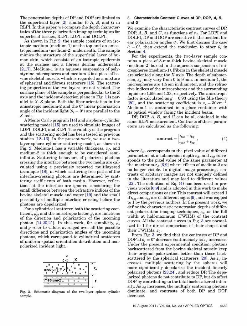
As shown in Fig. 2, the sample consists of an iso-tropic medium (medium-1) at the top and an aniso-tropic medium (medium-2) underneath. The samplemimics the structure of the superficial layer of hu-man skin, which consists of an isotropic epidermisat the surface and a fibrous dermis underneath[2,17]. Medium-1 is an aqueous suspension of poly-styrene microspheres and medium-2 is a piece of bo-vine skeletal muscle, which is regarded as a mixtureof spherical and fibrous scatterers [15]. The scatter-ing properties of the two layers are not related. Thesurface plane of the sample is perpendicular to the Zaxis and the incident-detection plane in Fig. 1 is par-allel to X–Z plane. Both the fiber orientation in theanisotropic medium-2 and the 0° linear polarizationangle of the incident light (θi ¼ 0°) are parallel to theX axis.
AMonte Carlo program [14] and a sphere–cylinderscattering model [15] are used to simulate images ofLDPI, DOLPI, and RLPI. The validity of the programand the scattering model has been tested in previousstudies [12–16]. In the present work, we use a two-layer sphere–cylinder scattering model, as shown inFig. 2. Medium-1 has a variable thickness, zd, andmedium-2 is thick enough to be considered semi-infinite. Scattering behaviors of polarized photonscrossing the interface between the two media are cal-culated using a previously reported multilayeredtechnique [18], in which scattering free paths of theinterface-crossing photons are determined by scat-tering coefficients of both media. However, reflec-tions at the interface are ignored considering thesmall difference between the refractive indices of thebovine skeletal muscle and water [19] and the smallpossibility of multiple interface crossing before thephotons are depolarized.
For a cylindrical scatterer, both the scattering coef-ficient, μs, and the anisotropic factor, g, are functionsof the direction and polarization of the incomingphoton [14,20,21]. In this work, for simplicity, μsand g refer to values averaged over all the possibledirections and polarization angles of the incomingphotons, which correspond to cylindrical scatterersof uniform spatial orientation distribution and non-polarized incident light.
3. Characteristic Contrast Curves of DP, DOP, A, B,and G
We examine the characteristic contrast curves of DP,DOP, A, B, and G, as functions of zd. For LDPI andDOLPI, DP and DOPare sensitive to the incident lin-ear polarization angles θi. We first discuss the caseθi ¼ 0°, then extend the conclusion to other θi inSection 4.
For the experiments, the two-layer sample con-tains a piece of 8-mm-thick bovine skeletal muscle(medium-2) buried in the aqueous suspension of mi-crospheres (medium-1). Fibers in the skeletal muscleare oriented along the X axis. The depth of submer-sion, zd, may vary from 0 to 9mm. In medium-1, themicrospheres are 1:5 μm in diameter, and the refrac-tive indices of the microspheres and the surroundingliquid are 1.59 and 1.33, respectively. The anisotropicfactor is calculated as g ¼ 0:93 using the Mie theory[20], and the scattering coefficient is μs ¼ 30 cm−1.Medium-1 is contained in a glass container withits optical window facing the incident beam.
DP, DOP, A, B, and G can be all obtained in thesame RLPI measurement. Contrasts of these param-eters are calculated as the following:
contrast ¼����itar − ibgitar þ ibg
����; ð4Þ
where itar corresponds to the pixel value of differentparameters at a submersion depth zd, and ibg corre-sponds to the pixel value of the same parameter atthe maximum zd [6,9] where effects of medium-2 areno longer visible. In digital image processing, con-trasts of arbitrary images are not uniquely definedin the literature and may lead to different values[22]. The definition of Eq. (4) has been used in pre-vious works [6,9] and is adopted in this work to makedirect comparisons easier. This contrast will exceed 1if itar and ibg are of different signs [9], and was cappedto 1 by the previous authors. In the present work, wedefine the characteristic penetration depths of differ-ent polarization imaging techniques, z0, as the fullwidth at half-maximum (FWHM) of the contrastcurves. All the contrast curves in Fig. 3 are normal-ized to 1 for direct comparison of their shapes andtheir FWHMs, z0.
From Fig. 3, we find that the contrasts of DP andDOP at θi ¼ 0° decrease continuously as zd increases.Under the present experimental condition, photonsbackscattered from the bovine skeletal muscle keeptheir original polarization better than those back-scattered by the spherical scatterers [20]. As zd in-creases, multiple scattering by the spheres willmore significantly depolarize the incident linearlypolarized photons [23,24], and reduce DP. The depo-larized photons do not contribute to DP, but do affectDOP by contributing to the total backscattered inten-sity. As zd increases, the multiply scattering photonsdominate, and contrasts of both DP and DOPdecrease.
Fig. 2. Schematic diagram of the two-layer sphere–cylindersample.
The width of the spatial distribution of the back-scattering intensity scales with the transport meanfree path lt ¼ 1=μ0s, where μ0s½≡ð1 − gÞμs� [25,19]. Sinceμ0s of the spherical scatterers is smaller than that ofthe bovine skeletal muscle [26], backscatteredphotons will spread out more as zd increases, andthe recorded backscattering intensity will decreasedue to the limited numerical aperture and sensitivearea of the imaging system. The relative variation ofDP is larger than that of DOP, which contains back-scattering intensity in the denominator. Similarly,the contrast of DP is also higher than that of DOP.However, the contrast curves of DP and DOP arenot significantly different since the relative variationof the total backscattered intensity is much smallerthan those of DP and DOP.
DOP represents the capability for the sample tomaintain the polarization of the incident light [9]and is insensitive to the illumination light intensity[2]. The characteristic depth, z0, of DOP indicates thedepth where the polarized light can reach and bringback the polarization information of the target.
Figure 3 shows that the contrast curve of G is dif-ferent from those of DP and DOP. Contrast of G stayshigh (>0:8) when zd is less than z0 of DOP, and thendrops quickly for bigger depth. It can be explainedfrom the origin of G [12]. When medium-2 is buriedin medium-1 as deep as z0 of DOP, the polarizedphotons can still reach the target and bring backits polarization information. The order of fiber align-ment of the target can then be detected by RLPI andcharacterized by G. When zd is larger than z0 of DOP,the photons lose its polarization and are no longerable to bring back the polarization information ofthe target, making G and its contrast drop quickly.
Although DP, DOP, A, B, and G all describe thesuperficial layer structure of the sample, their con-trast curves are different. The curve of A is similarto G and that of B is similar to DP and DOP.
To quantitatively investigate the penetrationdepth of DP, DOP, A, B, and G, we use Monte Carlosimulations to generate these images under similarexperimental conditions. In Fig. 2, spherical scat-terers in both medium-1 and medium-2 are 1:5 μm
in diameter, and cylindrical scatterers in medium-2 are 2:0 μm in diameter. The same liquid surroundsthe scatterers in the entire sample. Refractive in-dices of the spherical scatterers in medium-1 andmedium-2 are 1.59 and 1.4 [15], respectively, andthose of cylindrical scatterers and the liquid are1.4 and 1.33, respectively. The cylindrical scatterersare aligned along the X axis. The scattering coeffi-cient of medium-1 is 30 cm−1 and the anisotropic fac-tor is 0.93. The scattering coefficients of the sphericaland cylindrical scatterers in medium-2 are 30 and100 cm−1 [19], respectively, and the anisotropic fac-tors are 0.97 and 0.99, respectively. The thicknessof medium-2, t, is 2:0 cm, which is thick enough tobe considered semi-infinite. The thickness of med-ium-1, zd, changes from 0 to 9mm.
We calculate contrasts of DP, DOP, A, B, and G, asshown in Fig. 4. We can find that the shapes of thecontrast curves of DP, DOP, A, B, and G act similar tothat in Fig. 3. Also, z0 of DP, DOP, A, and G are con-sistent with the results obtained from experimentson the bovine skeletal muscle. Comparing Figs. 3and 4, our model works well and can be used to studythe depths of DP, DOP, and G.
Polarization angle of the incident linearly polar-ized light is not important for imaging isotropic med-ia [20], but may have significant effects for imaginganisotropic media, such as samples containing cy-lindrical scatterers [20,21]. In Section 4, characteris-tic depths of DP and DOP with different θi will beinvestigated.
The scattering in the medium-1 plays an impor-tant role in the contrast of DP, DOP, and G and theircharacteristic depths. Close examination of Figs. 3and 4 reveals that z0 of DOP is several mean freepath lengths lð≡1=μsÞ of medium-1, which is consis-tent with the results from previous research [8,9]. Wescale z0 of DOP using the transport mean free pathlength lt of medium-1, which describes the character-istic length for the photons to lose memory of theirincident direction in turbid medium. In Section 4,the scattering coefficient μs and the anisotropic factorg of medium-1 are changed and the characteristicdepths of DP, DOP, and G normalized by l and ltare discussed.
Fig. 3. Experimental contrast curves of DP, DOP, A, B, and Gwith different zd. The vertical line locates where zd is equal toz0 of DOP.
Fig. 4. Simulated contrast curves of DP, DOP, A, B, and G withdifferent zd.
A. Penetration Depths of DP and DOP at Different θiThe parameters from RLPI, A, B, and G are indepen-dent from the incident polarization angles [12], butthe contrast curves of DP and DOP are different atdifferent incident polarization. We examine the be-haviors of DP and DOP as functions of the incidentpolarization angle θi. Figures 5(a) and 5(b) showthe normalized contrast curves of DOP and DP at dif-ferent θi, and Fig. 5(c) shows the corresponding pene-tration depth, z0, as functions of θi. Figure 5(d) showsthe behaviors of itar and ibg, which correspond toDOPs of medium-2 and medium-1, respectively.
Figures 5(a) and 5(b) show that both DOP and DP,and their penetration depths, vary with incident po-larization, taking the maximum when the incidentlinear polarization is parallel to the fiber orientationin the sample. DOP is even more sensitive to θi thanDP. Figure 5(c) shows quantitatively that the pene-tration depths of both DOP and DP take theirmaximum around θi ¼ 0° and 180°, and a secondmaximum around θi ¼ 90°. The penetration depthof DP takes its minima around 45° and 135°. The pe-netration depth of DOP is not very well definedaround 30°, 60°, 120°, and 150°, where the curve var-ies sharply. Such behaviors can be explained by closeexamination of the polarization behaviors of the
backscattered photons from medium-1 (ibg) and med-ium-2 (itar). Figure 5(d) shows the behavior of DOP,but the arguments also apply to DP.
Figure 5(d) shows that, for backscattered photonsfrom the anisotropic sample medium-2 (itar), DOPvaries periodically with the incident polarization,θi, taking the maximum at θi ¼ 0° or 180° and a sec-ond maximum at θi ¼ 90°. This is consistent with thebehavior of polarized photon scattering by cylindricalscatterers. Backscattered photons retain their polar-ization better when the incident polarization and thecylindrical scatterers are parallel, but do less sowhen they are perpendicular [20]. For an arbitrarypolarization angle θi, the incident beam can be de-composed into two components of orthogonal polari-zations that are parallel or perpendicular to thefibers (cylindrical scatterers) in the anisotropicmedium. For incident polarization around 45° or135°, polarization of the backscattered photons bythe 0°-orientated fibers are projected almost equallyto the parallel and perpendicular polarization com-ponents, making both DP and DOP approach theirminima.
For backscattered photons from the isotropic sam-ples, medium-1 (ibg), DOP stays constant when theincident beam is perpendicular to the surface ofthe sample, but varies with the incident polarizationat oblique incidence. Figure 5(d) shows that ibg
Fig. 5. Experimental contrast curves of (a) DOP and (b) DP at different θi. The corresponding (c) z0 and (d) DOP at zd ¼ 0 are plotted asfunctions of θi.
reaches the maximum when the incident polari-zation is perpendicular to the X–Z incident-detection plane.
The behavior of itar and ibg explains the behavior ofthe penetration depth. The penetration depths of thepolarization sensitive measurements are determinedby how fast the photons are depolarized as they godeep into the sample. Th penetration depth is at itsmaximum when the incident polarization and theorientation of the fibers are parallel to each other be-cause depolarization is the slowest at this configura-tion, becomes lower when the two are perpendicularas depolarization gets faster, but approaches theminima when the two are in 45° or 135° since the in-cident photons quickly lose their polarization atthese polarization angles. As seen in Fig. 5(d), whenthe incident polarization angle θi is around 30°, 60°,120°, or 150°, itar is close to ibg and the contrast valuecalculated by Eq. (4) becomes close to zero. The con-trast curves may quickly drop to noise level [Fig. 5(a)and 5(b)], which results in poorly defined FWHM.This effect is more serious for DOP.
Therefore, when using LDPI, and particularlyDOLPI, on anisotropic samples, choosing incidentpolarization parallel to the orientation of the fiberswill result in better imaging quality and deeper pe-netration depth. In contrast, RLPI parameters areindependent on θi. For simplicity, we choose θi ¼ 0°for DP and DOP in the following analysis.
B. Relationship Between the Depths and the ScatteringProperties of Medium-1
In this subsection, we investigate the relationshipbetween penetration depths of different polarizationimaging techniques and the scattering properties ofmedium-1. We take G to represent RLPI for its clearphysical meaning.
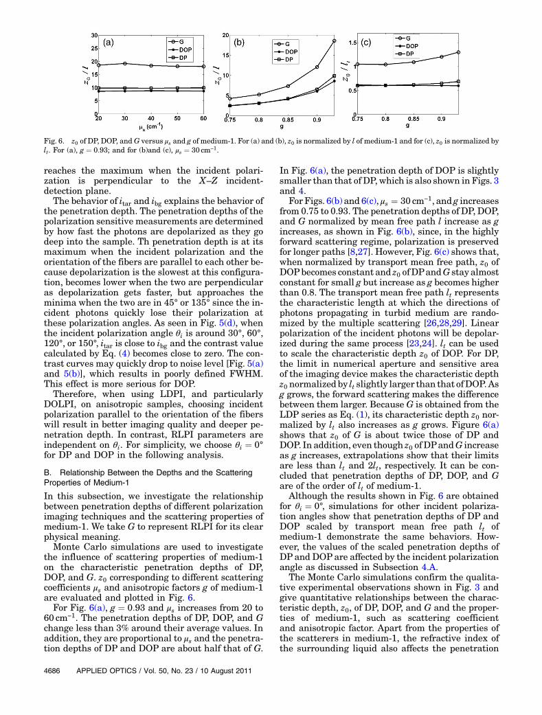
Monte Carlo simulations are used to investigatethe influence of scattering properties of medium-1on the characteristic penetration depths of DP,DOP, and G. z0 corresponding to different scatteringcoefficients μs and anisotropic factors g of medium-1are evaluated and plotted in Fig. 6.
For Fig. 6(a), g ¼ 0:93 and μs increases from 20 to60 cm−1. The penetration depths of DP, DOP, and Gchange less than 3% around their average values. Inaddition, they are proportional to μs and the penetra-tion depths of DP and DOP are about half that of G.
In Fig. 6(a), the penetration depth of DOP is slightlysmaller than that of DP, which is also shown in Figs. 3and 4.
For Figs. 6(b) and 6(c), μs ¼ 30 cm−1, and g increasesfrom 0.75 to 0.93. The penetration depths of DP, DOP,and G normalized by mean free path l increase as gincreases, as shown in Fig. 6(b), since, in the highlyforward scattering regime, polarization is preservedfor longer paths [8,27]. However, Fig. 6(c) shows that,when normalized by transport mean free path, z0 ofDOPbecomes constant and z0 ofDPandG stay almostconstant for small g but increase as g becomes higherthan 0.8. The transport mean free path lt representsthe characteristic length at which the directions ofphotons propagating in turbid medium are rando-mized by the multiple scattering [26,28,29]. Linearpolarization of the incident photons will be depolar-ized during the same process [23,24]. lt can be usedto scale the characteristic depth z0 of DOP. For DP,the limit in numerical aperture and sensitive areaof the imaging device makes the characteristic depthz0 normalized by lt slightly larger than that ofDOP.Asg grows, the forward scattering makes the differencebetween them larger. Because G is obtained from theLDP series as Eq. (1), its characteristic depth z0 nor-malized by lt also increases as g grows. Figure 6(a)shows that z0 of G is about twice those of DP andDOP. In addition, even though z0 ofDPandG increaseas g increases, extrapolations show that their limitsare less than lt and 2lt, respectively. It can be con-cluded that penetration depths of DP, DOP, and Gare of the order of lt of medium-1.
Although the results shown in Fig. 6 are obtainedfor θi ¼ 0°, simulations for other incident polariza-tion angles show that penetration depths of DP andDOP scaled by transport mean free path lt ofmedium-1 demonstrate the same behaviors. How-ever, the values of the scaled penetration depths ofDP and DOP are affected by the incident polarizationangle as discussed in Subsection 4.A.
The Monte Carlo simulations confirm the qualita-tive experimental observations shown in Fig. 3 andgive quantitative relationships between the charac-teristic depth, z0, of DP, DOP, and G and the proper-ties of medium-1, such as scattering coefficientand anisotropic factor. Apart from the properties ofthe scatterers in medium-1, the refractive index ofthe surrounding liquid also affects the penetration
Fig. 6. z0 of DP, DOP, andG versus μs and g of medium-1. For (a) and (b), z0 is normalized by l of medium-1 and for (c), z0 is normalized bylt. For (a), g ¼ 0:93; and for (b)and (c), μs ¼ 30 cm−1.
depths of DP, DOP, and G. Simulations show that anincrease in the refractive index of the liquid resultsin increases in z0 of DP, DOP, and G.
5. Conclusions
In this paper, penetration depths of LDPI, DOLPI,and RLPI have been studied for the anisotropic med-ium containing both cylindrical and spherical scat-terers buried in an isotropic scattering medium.The penetration depths of LDPI and DOLPI are com-pared with that of RLPI using both Monte Carlo si-mulations on a sphere–cylinder scattering model andexperiments on bovine skeletal muscle buried in anaqueous suspension of polystyrene microspheres.LDPI and DOLPI with different incident linear po-larization angles are analyzed in detail. The penetra-tion depths reach the maximum value when theincident linear polarization and the fibrous structurein the sample are parallel, and a second maximumwhen the two are perpendicular. Simulations alsoshow that the depth of DOLPI, and approximatelyof LDPI, scales with transport mean free path lengthof medium-1. The penetration depths of RLPI in-crease as the anisotropic factor g increases. Penetra-tion depths of LDPI, DOLPI, and RLPI are all of theorder of the transport mean free path length, and thelatter is almost twice as large as the former two.
This work has been supported by National NaturalScienceFoundation ofChina (NSFC, grants 60778044and 10974114), the China Postdoctoral Science Foun-dation (grant 20100480272) and the Ministry ofScience and Technology (grant 2006CB70570).
References1. A. Kienle, F. Forster, R. Diebolder, and R. Hibst, “Light propa-
gation in dentin: influence of microstructure on anisotropy,”Phys. Med. Biol. 48, N7–N14 (2003).
2. S. L. Jacques, J. R. Roman, and K. Lee, “Imaging skin pathol-ogy with polarized light,” J. Biomed. Opt. 7, 329–340 (2002).
3. X. Wang and L. V. Wang, “Propagation of polarized light inbirefringent turbid media: a Monte Carlo study,” J. Biomed.Opt. 7, 279–290 (2002).
4. S. G. Demos and R. R. Alfano, “Optical polarization imaging,”Appl. Opt. 36, 150–155 (1997).
5. S. P. Morgan and I. M. Stockford, “Surface-reflection elimina-tion in polarization imaging of superficial tissue,” Opt. Lett.28, 114–116 (2003).
6. H. R. Shao, Y. H. He, W. Li, and H. Ma, “Polarization-degreeimaging contrast in turbid media: a quantitative study,” Appl.Opt. 45, 4491–4496 (2006).
7. S. L. Jacques, J. R. Roman, and K. Lee, “Imaging superficialtissues with polarized light,” Lasers Surg. Med. 26, 119–129(2000).
8. Y. Liu, Y. L. Kim, X. Li, and V. Backman, “Investigation ofdepth selectivity of polarization gating for tissue characteriza-tion,” Opt. Express 13, 601–611 (2005).
9. R. Nothdurft and G. Yao, “Expression of target optical proper-ties in subsurface polarization-gating imaging,” Opt. Express13, 4185–4195 (2005).
10. S. Nickell, M. Hermann, M. Essenpreis, T. J. Farrell, U.Krämer, and M. S. Patterson, “Anisotropy of light propagationin human skin,” Phys. Med. Biol. 45, 2873–2886 (2000).
11. X. Y. Jiang, N. Zeng, Y. H. He, and H. Ma, “Investigation oflinear polarization difference imaging based on rotation of in-cident and backscattered polarization angles,” Prog. Biochem.Biophys. 34, 659–663 (2007).
12. R. Liao, N. Zeng, X. Y. Jiang, D. Z. Li, T. Yun, Y. H. He, andH. Ma, “A rotating linear polarization imaging techniquefor anisotropic tissues,” J. Biomed. Opt. 15, 030614 (2010).
13. N. Zeng, X. Jiang, Q. Gao, Y. He, and H. Ma, “Linear polariza-tion difference imaging and its potential applications,” Appl.Opt. 48, 6734–6739 (2009).
14. T. Yun, N. Zeng,W. Li, D. Li, X. Jiang, andH.Ma, “Monte Carlosimulation of polarized photon scattering in anisotropicmedia,” Opt. Express 17, 16590–16602 (2009).
15. H. He, N. Zeng, R. Liao, T. Yun, W. Li, Y. He, and H. Ma,“Application of sphere–cylinder scattering model to skeletalmuscle,” Opt. Express 18, 15104–15112 (2010).
16. H. He, N. Zeng, W. Li, T. Yun, R. Liao, Y. He, and H. Ma, “Two-dimensional backscattering Mueller matrix of sphere–cylinder scattering medium,” Opt. Lett. 35, 2323–2325 (2010).
17. T. Maeda, N. Arakawa, M. Takahashi, and Y. Aizu, “MonteCarlo simulation of spectral reflectance using a multilayeredskin tissue model,” Opt. Rev. 17, 223–229 (2010).
18. L. H. Wang, S. L. Jacques, and L. Q. Zheng, “MCML—MonteCarlo modeling of light transport in multi-layered tissues,”Comput. Methods Programs Biomed. 47, 131–146 (1995).
19. V. Tuchin, “Methods and algorithm for the measurement ofthe optical parameters of tissues,” in Tissue Optics: Light Scat-tering Method and Instruments for Medical Diagnosis, 2nd ed.(SPIE, 2007), pp 144–191.
20. H. C. van de Hulst, “Circular cylinders,” in Light Scattering bySmall Particles (Dover, 1981), Chap. 15, pp. 297–328.
21. A. Shuaib and G. Yao, “Equi-intensity distribution of opticalreflectance in a fibrous turbid media,” Appl. Opt. 49, 838–844(2010).
22. E. Peli, “Contrast in complex images,” J. Opt. Soc. Am. A 7,2032–2040 (1990).
23. X. Li, J. C. Ranasinghesagara, and G. Yao, “Polarization-sensitive reflectance imaging in skeletal muscle,” Opt.Express 16, 9927–9935 (2008).
24. D. Bicout, C. Brosseau, A. S. Martinez, and J. M. Schmitt,“Depolarization of multiply scattered waves by sphericaldiffusers: influence of the size parameter,” Phys. Rev. E 49,1767–1770 (1994).
25. T. J. Farrell, M. S. Patterson, and B. Wilson, “A diffusion the-ory model of spatially resolved, steady-state diffuse reflec-tance for the noninvasive determination of tissue opticalproperties in vivo,” Med. Phys. 19, 879–888 (1992).
26. J. Xia, A. Weaver, D. E. Gerrard, and G. Yao, “Monitoring sar-comere structure changes in whole muscle using diffuse lightreflectance,” J. Biomed. Opt. 11, 040504 (2006).
27. V. Sanharan, M. J. Everett, D. J. Maitland, and J. T. Walsh,“Comparison of polarized-light propagation in biological tis-sue and phantoms,” Opt. Lett. 24, 1044–1046 (1999).
28. G. Marquez, L. V. Wang, S.-P. Lin, J. A. Schwartz, and S. L.Thomsen, “Anisotropy in the absorption and scattering spec-tra of chicken breast tissue,” Appl. Opt. 37, 798–804 (1998).
29. N. Garcia, A. Z. Genack, and A. A. Lisyansky, “Measurement ofthe transport mean free path of diffusing photons,” Phys. Rev.B 46, 14475–14479 (1992).