1 1. Introduction Currently, fuel grade ethanol is used primarily as an additive in gasoline, but it is increasingly being used as a primary fuel source. Demand for fuel grade ethanol is driven by the automobile fuel market. Demand is also driven by the societal goal to use environmentally friendly fuels. Fuel grade ethanol offers many advantages as an environmentally friendly fuel. The combustion of fuel grade ethanol produces cleaner emissions than gasoline. The use of fuel grade ethanol reduces the use of fossil fuels. Also, ethanol can be generated from renewable resources, notably corn. However, to realize these benefits, the production of fuel grade ethanol must be efficient and profitable. Processes for the production of fuel grade ethanol are the study of this project. 2. Problem Statement The team will design an environmentally friendly process for the production of fuel grade ethanol while reducing the strain on foodstuff production. The process must be capable of generating a steady supply of ethanol. These goals will be achieved by increasing the efficiency of ethanol processes based on foodstuffs or by using a source that does not strain the food supply. 3. Objectives The proposed plant must meet these design objectives: 1. Design an economically feasible plant for the production of fuel grade ethanol. 2. Determine the best source of ethanol production. 3. Determine the amount of ethanol to be produced. 4. Design a plant that promotes safe working conditions. 5. Design a plant that promotes environmental stewardship 6. Design for efficient use of energy. 7. Produce fuel grade ethanol according to American Society of Testing Materials (ASTM) standards.
Transcript
1
1. Introduction
Currently, fuel grade ethanol is used primarily as an additive in gasoline, but it is increasingly
being used as a primary fuel source. Demand for fuel grade ethanol is driven by the automobile fuel
market. Demand is also driven by the societal goal to use environmentally friendly fuels. Fuel grade
ethanol offers many advantages as an environmentally friendly fuel. The combustion of fuel grade ethanol
produces cleaner emissions than gasoline. The use of fuel grade ethanol reduces the use of fossil fuels.
Also, ethanol can be generated from renewable resources, notably corn. However, to realize these
benefits, the production of fuel grade ethanol must be efficient and profitable. Processes for the
production of fuel grade ethanol are the study of this project.
2. Problem Statement
The team will design an environmentally friendly process for the production of fuel grade ethanol
while reducing the strain on foodstuff production. The process must be capable of generating a steady
supply of ethanol. These goals will be achieved by increasing the efficiency of ethanol processes based
on foodstuffs or by using a source that does not strain the food supply.
3. Objectives
The proposed plant must meet these design objectives:
1. Design an economically feasible plant for the production of fuel grade ethanol.
2. Determine the best source of ethanol production.
3. Determine the amount of ethanol to be produced.
4. Design a plant that promotes safe working conditions.
5. Design a plant that promotes environmental stewardship
6. Design for efficient use of energy.
7. Produce fuel grade ethanol according to American Society of Testing Materials (ASTM)
standards.
2
8. Simulate and optimize the plant process.
4. Importance of Fuel Grade Ethanol
The production of fuel grade ethanol steadily increased over the past two decades. Ethanol is
most commonly used as a gasoline additive. Ethanol is blended with gasoline to increase the octane rating
as well as to improve the emission quality of the gasoline engine. Fuel grade ethanol has a high octane
rating of 116. Ethanol burns cleanly due to its oxygen content. In most regions of the United States,
ethanol is blended up to 10% by volume with conventional gasoline, this blend is called E10 and can run
in any engine designed to run on conventional gasoline.
The increase in demand of ethanol can be traced to the passing of the Clean Air Act in 1990,
which set limits on the amount of pollutants found in the air anywhere in the United States. States with
heavy air pollution must use oxygenated gasoline to reduce emissions from motor vehicles. The demand
for ethanol did not begin to increase rapidly until 1999 (Figure 4.1). Until 1999, methyl tert-butyl ether
(MTBE) was the fuel additive of choice. However, MTBE, a potential carcinogen, was found in the
groundwater that supplies cities. The source of the MTBE was traced to leaking underground gasoline
storage tanks. Since MTBE is highly soluble in water, it quickly contaminated the ground water. Due to
ethanol’s increased use as an additive, the production of ethanol increased tenfold from 1996 to 2004.
The increased percent of ethanol in gasoline has one drawback: ethanol has a lower heat of combustion
than conventional gasoline. This means the blended gasoline provides less energy than conventional
gasoline. Thus, an engine will require more of the blended fuel to do the same amount of work as an
engine running on conventional gasoline. However, when blended at low levels, around ten percent by
volume, the effect on fuel economy is small.
Ethanol can also be used as a motor fuel in concentrations up to 85 percent by volume. This
mixture, called E85, powers flexible-fuel vehicles. These vehicles can run on fuels that range in ethanol
3
concentration from 0% to 85%. A standard conventional gasoline engine can run on fuel with an ethanol
concentration from 0-20% without modification.
Figure 4.1: Annual Production of ethanol has grown more rapidly in the last decade in the U.S.
5. Alternative Feedstock Solutions
An important decision in the process is determining the type of feedstock to be used. The
feedstock is the material that will be converted into fuel grade ethanol. Research indentified three
potential options: corn stalks, switch grass, and carbon dioxide. These options are discussed in detail
in the following sections.
5.1. Corn Stalks
The process for producing ethanol from corn takes place in eight steps (Appendix A). The
process begins with the cleaning of the corn and removal of the unwanted sections such as stalk and
cob. These rejected components are combined with the byproducts stream, which becomes animal
feed. Most processes use only the starch-rich corn kernels for ethanol production. An alternative is to
take these rejected components and convert them to ethanol, using a process similar to switchgrass
conversion to ethanol (see section 5.2).
4
After being separated, the starch-rich kernels move to the steeper where the larger molecules
are broken down to smaller molecules for the later fermentation process. The steeper is a humid
environment with sulfur dioxide fed to increase acidity and to prevent unnecessary bacteria growth.
This product moves to a cyclone separator, which removes the germ from the rest of the kernel. Then,
oil is washed out of the germ. The germ becomes part of the animal feed, while the oil is sold as corn
oil. The remaining kernel fibers, cornstarch, and gluten are combined with water to form a slurry.
The remaining kernel fibers are removed and combined with the animal feed. The cornstarch and
gluten are separated by their differing densities using a hydrocyclone. The gluten is sent to the animal
feed. Once the cornstarch is separated from the gluten, it is converted to a syrup of dextrose, which is
used as the feed for the fermentation process. The syrup is fermented by bacteria producing carbon
dioxide and an ethanol solution. The ethanol is then separated from the solution and sold. The
remaining solution is dried and combined with the animal feed.
5.2. Switchgrass
Switchgrass is comprised mainly of lignocellulosic materials, making switchgrass more
difficult to ferment into ethanol than conventional starch and sugar crops. This challenge stems from
the structure of the lignocellulose, which is comprised of three major components. The three primary
components are crystalline cellulose, hemicellulose, and lignin comprising roughly of 50, 25, and 25
percent by mass of the cellulosic material, respectively. Extra processing steps are required for each
component.
Ethanol is generated from switchgrass in a multi-step process (Appendix A). Upon entering
the system, lignocellulose is pretreated to separate the crystalline cellulose from the xylose
(hemicellulose) and the lignin. The crystalline cellulose, the most difficult to break down, continues
to an acid or enzyme catalyzed hydrolysis which breaks the cellulose down to glucose. The glucose
5
and xylose undergo fermentation. The resulting product is sent to a distillation train and concentrated
to fuel grade levels.
The lignin is a phenolic polymer which is catalytically broken down into one or two phenyl
groups. These phenol groups are then reacted with oxygen to remove their side groups and are
further reacted with methanol to form Methyl-aryl esters. These esters are a valuable additive to
gasoline for their octane enhancing properties. These esters increase the profitability of this process.
5.3. Carbon Dioxide
Another alternative for an ethanol production process feedstock is carbon dioxide, through
the use of genetically modified cyanobacteria. A Process Flow Diagram (PFD) for this process is
shown in Appendix A. A strain of Synechocystis has been genetically modified by Professor Fu at
the University of Hawaii to produce ethanol from carbon dioxide via a photosynthetic pathway. The
aqueous cyanobacteria in solution use sunlight in a photobioreactor to convert the carbon dioxide to
ethanol. Currently, the process can produce concentrations of 15 mM of ethanol in 5 days in a batch
reactor. The concentration of ethanol is limited to 15 mM because higher concentrations of ethanol
kill the bacteria. The liquid solution containing water, nutrients, and carbon dioxide is then separated
using several techniques to yield a high purity ethanol product. As this is a new process, no large
scale industrial processes exist to base the separation process on. Separation possibilities are
discussed in section 10.3.
6. Process Determination – Decision Matrix
The processes described above were evaluated using the criteria in a decision matrix (Table
6.1). The process chosen was cyanobacteria. Cyanobacteria excelled in the areas of sustainability,
renewability, stewardship, cost, environmental acceptance, and environmental impact. In the
following section each of the criteria are discussed in detail to explain the evaluations.
6
Table 6.1: Decision Matrix Criteria
Process
Criteria Weight Corn Grass Algae
1 Resource Availability 5 5 4 3
2 Convenience of energy utilization 10 4 4 6
3 Efficiency of conversion 10 5 2 4
4 Technological feasibility 10 8 7 5
5 Portability and ease of transportation 5 3 2 5
6 Sustainability 10 3 3 8
7 Renewability and Stewardship 10 7 8 10
8 Cost and affordability 15 8 5 11
9 Safety and health effects 10 8 8 8
10 Environmental acceptance and impact 15 10 9 14
Total 100 61 52 74
6.1. Availability, Renewability and Stewardship, and Sustainability
Important considerations for alternative fuel sources are the availability, renewability and
sustainability of the feedstock. The source for ethanol production needs to be readily available to
produce ethanol year round. Corn and switchgrass are grown in enormous quantities and are
easily replanted and regrown annually. The cellulose based sources are readily available in large
quantities, especially in the Midwest. Professor Fu’s modified cyanobacteria are easily sustained
once initial growth has begun, but his cyanobacteria are not yet commercially available.
Consequently, cellulose sources are rated higher in availability, while cyanobacteria are rated
higher in renewability and sustainability. These factors could be tied in to one higher weighted
factor, but it was decided that the differences between renewability, sustainability and availability
were significant enough to be independent categories.
6.2. Environmental Impact, Health and Safety Effects
Important factors in deciding on a process are environment effect and any health and
safety issues for the operators. The source should have a minimal impact on the environment,
7
meaning that waste streams from the process are either non-toxic or will be treated before
released into the environment. Also the production of the source needs to have a minimal impact
on the environment as well. Corn stalks and switch grass have an environmental impact during
the growth phase because of the land required to produce these crops. Also, pesticides and
fertilizers can have a negative impact on the environment. The use of cyanobacteria has a
minimal impact on the environment because it is grown in a reactor and all waste streams are
controlled and treated. Cyanobacteria have a neutral effect on the environment because it uses
CO2 as a source for producing ethanol. When the ethanol is used, the same amount of CO2 is
released into the atmosphere as was supplied by the CO2 feed stream used to create the ethanol.
All three fuel source options have minimal health and safety issues because a minimal
amount of hazardous materials are present in the process. The main safety issues that arise are
from plant design. A plant that promotes safe working conditions for operators and residents in
the area of the plant is an important aspect of the design.
6.3. Cost and Affordability
The costs associated with a given fuel source are an important consideration for the
design process. Maintaining low cost is a high priority in a competitive market. Each of the fuel
source options have different costs associated with production. Corn stalks and switchgrass have
relatively high costs in the growing process, and the techniques to convert these to ethanol are
inefficient. Cyanobacteria are a lower cost option because the cyanobacteria reproduce while
making ethanol. The major cost with using cyanobacteria is that the process requires a large
volume of cyanobacteria in solution to produce a significant amount of ethanol. A large volume
results in high equipment costs.
8
6.4. Convenience of Energy Utilization, Efficiency of Conversion
To provide a feasible fuel ethanol production process, the ease of obtaining the feed
source and efficiency at which the source can be converted to fuel must be taken into account.
Corn and switchgrass were not rated highly in the convenience of energy utilization because they
must be transported to the production facility. This fuel cost for transportation detracts from the
goal of providing fuel. The cyanobacteria can be grown and regenerated on site, right next to the
acid gas stacks of a gas sweetening processes. Gas sweetening plants refine natural gas and can
provide a vapor stream rich in carbon dioxide directly the cyanobacteria.
No sources agree on the efficiency of cellulose based conversions where the efficiency is
defined as the amount of energy provided to the process versus the amount of energy produced.
Corn based plants claim an efficiency of around 50%. The process of conversion is highly energy
intensive which lowers the score in this category. Switch grass is claimed to be anywhere from
50% to 400 % from cellulose to energy conversion. The cyanobacteria has the lowest conversion,
producing only 15mM ethanol solutions, but the conversion process involves no extra energy
since it is a photosynthetic reaction. Since the actual efficiency is unknown, the cyanobacteria
feed was scored the same as corn.
6.5. Technological Feasibility
Another consideration for the design of an ethanol producing process is the technological
feasibility. Technological feasibility was a criterion for deciding on alternatives to research. The
score is based upon the actual documentation of processes that would contribute to design. The
availability of literature, research, and operating experience contribute to determining if the
process could be taken from concept to reality.
9
For a corn based plant, determining feasibility is obvious, as several corn based ethanol
plants are in operation throughout the Midwest. Feasibility was, however, ranked somewhat
lower for corn based process because the project would focus on using the entire corn stalk,
which is not the case with current corn fed ethanol processes. A switch grass based plant is also
technologically feasible. The processes needed to convert the grass to ethanol are very similar to
the corn plants already in use, although they have not already been commercialized specifically
for grass. The process to convert carbon dioxide to ethanol has been proven feasible on a bench
top scale by Fu’s patent. The feasibility of a full scale separation process from a low
concentration of ethanol is feasible, but unconventional. Further discussion of the separation
feasibility is discussed in section 10.3. Since much is unknown about scale up of this process, it
was given a lower ranking than cellulose bases.
7. Intellectual Properties Issues
Intellectual property is the basis for technological innovation. The ideas of others will be and
have been used to complete this project, but these ideas must be respected. Some of the technology
and information used in this ethanol production process is covered by patents, while other information
is provided by research publications. These sources must be properly recognized, avoiding
infringement and plagiarism. Also, to gain access to Professor Fu’s patented research, this team
signed non-disclosure agreements with him. Care must be exercised to respect this agreement, and
confidential information may not be divulged.
7.1. Professor Fu’s Patent
Professor Fu of the University of Hawaii genetically modified a strain of Synechocystis
cyanobacteria to produce ethanol from carbon dioxide via a photosynthetic pathway. Professor
Fu holds a patent on this technology. The patent governs the sequence of the gene used to modify
10
the cyanobacteria. An ethanol production process developed using this technology must work
with the patent holder.
Professor Fu also provides this team with details of his own research. He has been
contributing his experience and sources for further investigation for the development of the
production process.
7.2. Keyes Patent
The Keyes patent established heterogeneous distillation of ethanol from an ethanol-water
mixture. This technology provides a means to achieve ethanol concentrations above the ethanol-
water azeotrope (see section 10.3.4).
7.3. Research Sources
Research literature is excellent resource for nearly all aspects of this project. Information
from research literature is referenced (see section 14).
8. Task Specifications
Once a feedstock was chosen and the necessary research preformed, different tasks were
completed to determine project feasibility. To establish feasibility three things must be determined:
the purity and composition of fuel grade ethanol, an energy balance to find locations with sufficient
sunlight, and a feasible level of production.
8.1. Ethanol Quality
The ethanol produced must comply with the ASTM specifications for Fuel Ethanol standard
D4806-98. An abridged version of the specfications is shown in table 8.1.1:
11
Table 8.1.1: ASTM fuel specifications (abridged)
Properties Specifications
1 Ethanol, %v/v: 92.1 min.
2 Methanol, %v/v: 0.5 max. (5,000 ppm)
3 Water, % v/v: 1.0 max. (10,000 ppm)
4 Denaturant: A min of 1.96% v/v, and a max of
4.76% v/v of natural gasoline, gasoline
components or unleaded gasoline.
The full table of specifications required can be found in appendix B.
8.2. Energy Balance
One major specification for this design is providing the amount of sunlight needed by the
cyanobacteria to produce ethanol. If no location provide the amount of light energy required for
conversion, the process is not feasible. The energy balance must show that the cyanobacteria are able
to harness at least 240 W/m2 of sunlight, the amount of energy used in the successful experiments by
Professor Fu. More information on the energy balance is provided in section 10.1.
8.3. Production Level
Many options were considered for a base case. The base case defines the approximate scale
of the production process. A full scale ethanol production plant based on the production levels of
current fuel grade ethanol production facilities was considered. However, to produce ethanol on that
large scale and still remain competitive would take an excessively large reactor. Many small scale
options were then considered. One possible option would be to use the CO2 from an amine gas
sweetening plant (see sections 6.4 and 10.2). Another option would use the CO2 stack from a power
plant. For both of these cases the idea would be to reduce CO2 emissions and produce a sellable
product. The amine gas sweetening plant was chosen as a basis because many of these plants are
12
located in Western Texas where there is ample sunlight to drive the photosynthetic reaction. More
information on the basis is given in section 10.2.
9. Design Norms
Christian engineers are uniquely called to live out their faith and redeem the creation while
maintaining profitability. When designing a project, one of the best ways to incorporate both of these
views is to create a set of design norms on which to base decisions. Applying design norms can be as
simple as designing an item that can be made cost-effectively but still be of high quality so as not to
break after the millionth use by the consumer. The most relevant design norms are discussed further.
9.1. Stewardship of Resources
Engineers have a responsibility in designing projects to the environment and community. To
maximize benefits of the plant design, and minimize the environmental impact, the design must be
energy and resource efficient. By harnessing solar energy to power the bioreactor and by recycling
water, this design is intended to use resources as efficiently as possible. At the same time, the plant is
converting emissions, which normally are given off to the atmosphere in an amine gas sweetening
processes, to a usable form of energy. This use not only provides a carbon dioxide source for our
plant, but helps to preserve the environment.
9.2. Justice
Energy should be available and affordable for all people. Inexpensive energy should not
have to compete with basic human needs for food. Current ethanol production processes deplete
food resources by converting these resources into fuel. This plant design produces fuel ethanol
from waste gas emissions and eliminates the need to convert food to fuel allowing agricultural lands
to revert to food production. The plant also creates a fuel resource that the general public can
afford as energy prices continue to rise.
13
9.3. Transparency
This plant is being designed so that it can easily be replicated for any natural gas pumping
stations in West Texas. In this way a significant amount of fuel ethanol can be produced.
Requirements and parameters will be clear so that the plans can be transferred to other plants with
only minor modifications to suit the unique configurations of each plant. The plant must be easy to
operate and maintain.
9.4. Trust
When designing, the engineer’s responsibility is to the public to make sure the plant is safe
for the surrounding community. Worst case scenarios as well as conditions for steady state and
unsteady state operations must be considered to ensure that the plant will not fail, or cause safety
hazards in the event of plant failure.
10. Preliminary Design
When solving a problem a good starting point is a material and energy balance; this allows an
initial determination of the feasibility of the process. Preliminary calculations were performed to
address critical design issues. Initially an energy balance was performed to determine whether there
were suitable conditions for ethanol production and at what regional locations. Next a material
balance was performed to determine the basis, the amount of ethanol to be produced and the size of
the reactor. Finally a series of alternative separation systems were chosen and their specifications
were roughly calculated using HYSYS design software.
10.1 Energy Balance
The purpose of the energy balance is to determine if the proper amount of sunlight can
reach the cyanobacteria. According to Professor Fu, the necessary light flux needed to convert
CO2 to ethanol is 100 μeinsteins/m2s. This can be converted into an energy flux of 240 W/m
2. A
14
full calculation can be found in appendix C. To find the energy flux from the sun in different
areas of the United States, the Average Daily Solar Radiation map was used (appendix C). This
provided the basis for determining the possible location of the ethanol plant. The calculations
were conducted using a value of 6.5 kWh/m2day because the majority of the US was in the
region of 6-7 kWh/m2day. This provided an energy flux of 270 W/m
2, making the process
feasible in sunny regions of the US. Since the calculated flux was close to the minimum amount
necessary, it was determined to locate the ethanol production facilities in places that receive
solar radiation greater than 7 kWh/m2day. A safety factor in this respect was necessary because
calculations were based off of average values of solar radiation not minimums. This limits the
plant location to regions of Arizona, New Mexico and Texas.
10.2 Material Balance
Initially a production volume of 1,000,000 liters of ethanol per year was chosen as the
basis for calculations. From data acquired from Professor Fu, the final concentration of ethanol
in the reactor solution was 15 mM of ethanol after a five day operational cycle. Accounting for
maintenance and other down time, an operational time of 300 days per year was chosen. On the
basis, the necessary reaction mixture volume for a five day run, or five day residence time, would
be very large. Subsequently, a tubular or plug flow reactor (PFR) providing adequate surface
area for sunlight would be several hundred kilometers long (Table 10.2.1). A continuous stirred
tank reactor (CSTR) would also be large – large enough for the reaction mixture volume.
Upon completion of the preliminary basis the equipment sizes were found to be
excessively large. It was then decided to design a plant to complement current CO2 producing
facilities instead of designing an autonomous, full scale production facility. Gas sweetening
plants in western Texas seem suitable due to their steady production of CO2 and the large amount
of annual sunlight. The information of a gas sweetening plant was obtained from Steve Brusso,
an engineer with NATCO Group Inc. (Appendix D). With the information provided on process
15
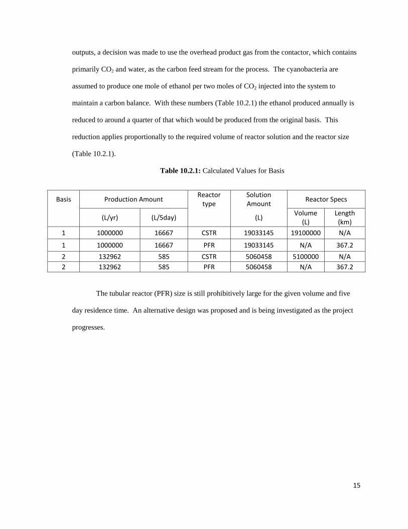
outputs, a decision was made to use the overhead product gas from the contactor, which contains
primarily CO2 and water, as the carbon feed stream for the process. The cyanobacteria are
assumed to produce one mole of ethanol per two moles of CO2 injected into the system to
maintain a carbon balance. With these numbers (Table 10.2.1) the ethanol produced annually is
reduced to around a quarter of that which would be produced from the original basis. This
reduction applies proportionally to the required volume of reactor solution and the reactor size
(Table 10.2.1).
Table 10.2.1: Calculated Values for Basis
Basis Production Amount Reactor
type Solution Amount
Reactor Specs
(L/yr) (L/5day) (L) Volume
(L) Length
(km)
1 1000000 16667 CSTR 19033145 19100000 N/A
1 1000000 16667 PFR 19033145 N/A 367.2
2 132962 585 CSTR 5060458 5100000 N/A
2 132962 585 PFR 5060458 N/A 367.2
The tubular reactor (PFR) size is still prohibitively large for the given volume and five
day residence time. An alternative design was proposed and is being investigated as the project
progresses.
16
CO2
Processes
CO2 in from Gas
Sweetening Plant
Clear Reactor Piping
Concentration Recycle
Feeds and Products
CO2 to Reactor
Figure 10.2.1: Preliminary Reactor Design
In the preliminary design (Figure 10.2.1), the large circles that make up the array are Continuous
Stirred Tank Reactors (CSTRs) where the CO2 is injected into the system. Also, a small recycle
stream connects different CSTRs to maintain a constant concentration of ethanol over the whole
reactor to generalize it as a large CSTR. The lines leading to and from points on the “crown” are
banks of clear tubes used to maximize the cyanobacteria’s solar exposure. The circles at the ends
could possibly be more mixing points or just representative of return points. This array would be
arced around the sweetening plant facing the southern hemisphere to create more surface area for
the solar contact. This design also centralizes all points where the CO2 is injected reducing the
piping requirement for transporting the CO2. As a final note, the amount of CSTRs and pipe
banks is representative of reactor layout and not design specification.
The design of the CSTR reactor was changed from the outward arcing array seen above
in Figure 10.2.1 to the rectangular design in Figure 10.2.2. The decision to make the change was
based on the amount of land required for each reactor. The rectangular design uses less land area
for the same reactor volume.
17
Figure 10.2.2: Second Preliminary Reactor Design
From calculations based on the desired ethanol production level and the residence time required
in the reactor, it was determined that 38 pairs of mixing vessels are required. The large mixing
vessels will incorporate a heat exchanger designed to cool the reactor fluid preventing the
temperature from increasing to the point where the bacteria die. Each tube bank is comprised of 4
rows 32 tubes high with an equal number of tubes having flow in each direction. These tubes are
2 3/8 inches in diameter with a span of 48 m. This allows for optimal sunlight for conversion as
well as aiding to maintain a stable concentration throughout the overall reactor.
10.3 Separation
Once ethanol is produced in the reactor, the ethanol must be separated from the reaction
mixture and purified to ASTM standards for fuel-grade ethanol (Table 8.1.1). The challenges to
the design of the separation process include recovering ethanol from the dilute reaction mixture,
purifying the resulting ethanol-water mixture, and moving the ethanol-water mixture past its
azeotrope up to fuel-grade specifications. An azeotrope occurs when the composition of a mixture
is the same in the liquid and vapor phases. At an azeotrope, separation technologies that function
based on difference in liquid and vapor composition fail to separate the components of a mixture.
Many separation technologies are investigated with regard to these challenges. Possibly, one
18
technology could fulfill this separation process. However, the separation process will likely make
use of many of the separation technologies. The technologies investigated include membranes,