Model 9910-DBS200 Model 9910-DBA200 Max flow: 49.8 gpm Max pressure: 725 psi Max speed: 550 rpm 4 Diaphragms Model 9910-DBS160 Model 9910-DBA160 Max flow: 39.7 gpm Max pressure: 725 psi Max speed: 550 rpm 4 Diaphragms Model 9910-DBS140 Model 9910-DBA140 Max flow: 37.6 gpm Max pressure: 725 psi Max speed: 550 rpm 3 Diaphragms Model 9910-DBS110 Model 9910-DBA110 Max flow: 28.5 gpm Max pressure: 725 psi Max speed: 550 rpm 3 Diaphragms Heavy-duty, high pressure diaphragm pumps. These industrial-built pumps are designed to handle all of your high pressure and volume diaphragm pump needs with minimal maintenance required. Their innovative, external manifold design allows for normal servicing to be done from one side of the pump, thereby eliminating the need for dismounting. These pumps are excellent for chemical spraying where higher pressures are desired, such as insecticide spraying, air blast and tall tree sprayers. They also work great for high pressure cleaning and dis- infecting applications, such as poultry house cleaners. Control Units 9910-GH50 & 9910-BMH50 Control units are available for easy flow and pressure control of your sprayer system. These units include a pressure relief valve to control pressure, an oil-filled pres- sure gauge to monitor pressure, and an outlet valve to control flow. Control unit 9910-BMH50 can be remote mounted with Kit No. 9910-KIT999. Refer to the adjoining chart to select the proper control unit for your pump. Description High Pressure Diaphragm Pumps Installation, Operation, Repair and Parts Manual Form L-1384 12/11, Rev. B Control Max. Max. Pump Unit Model GPM PSI Model 9910-GH50 51 725 All models 9910-BMH50 41 725 All 110,140 and 160 Series
Transcript
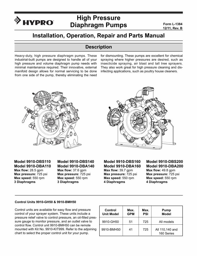
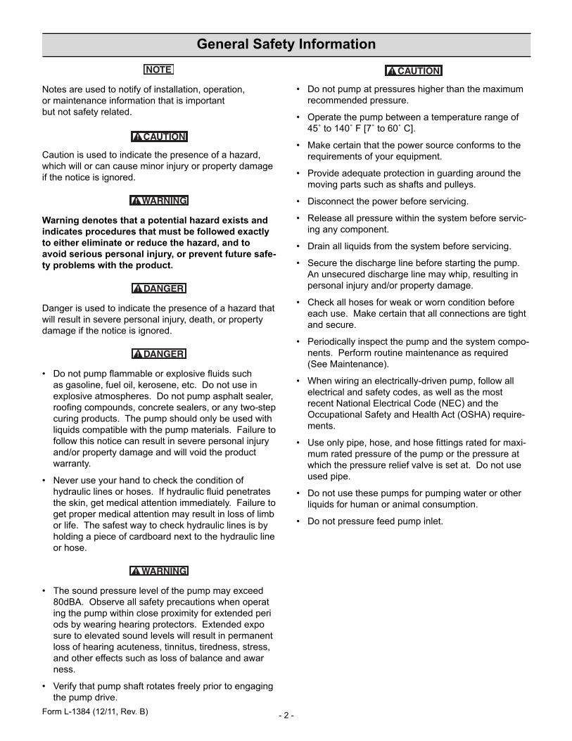
Model 9910-DBS200Model 9910-DBA200Max flow: 49.8 gpm Max pressure: 725 psiMax speed: 550 rpm 4 Diaphragms
Model 9910-DBS160Model 9910-DBA160Max flow: 39.7 gpmMax pressure: 725 psi Max speed: 550 rpm 4 Diaphragms
Model 9910-DBS140Model 9910-DBA140Max flow: 37.6 gpm Max pressure: 725 psiMax speed: 550 rpm 3 Diaphragms
Model 9910-DBS110Model 9910-DBA110Max flow: 28.5 gpmMax pressure: 725 psi Max speed: 550 rpm 3 Diaphragms
Heavy-duty, high pressure diaphragm pumps. Theseindustrial-built pumps are designed to handle all of yourhigh pressure and volume diaphragm pump needs withminimal maintenance required. Their innovative, externalmanifold design allows for normal servicing to be donefrom one side of the pump, thereby eliminating the need
for dismounting. These pumps are excellent for chemicalspraying where higher pressures are desired, such asinsecticide spraying, air blast and tall tree sprayers. They also work great for high pressure cleaning and dis-infecting applications, such as poultry house cleaners.
Control Units 9910-GH50 & 9910-BMH50
Control units are available for easy flow and pressurecontrol of your sprayer system. These units include apressure relief valve to control pressure, an oil-filled pres-sure gauge to monitor pressure, and an outlet valve tocontrol flow. Control unit 9910-BMH50 can be remotemounted with Kit No. 9910-KIT999. Refer to the adjoiningchart to select the proper control unit for your pump.
Description
High PressureDiaphragm Pumps
Installation, Operation, Repair and Parts Manual
Form L-138412/11, Rev. B
Control Max. Max. PumpUnit Model GPM PSI Model
9910-GH50 51 725 All models
9910-BMH50 41 725 All 110,140 and 160 Series
- 2 -
Notes are used to notify of installation, operation, or maintenance information that is important but not safety related.
Caution is used to indicate the presence of a hazard,which will or can cause minor injury or property damageif the notice is ignored.
Warning denotes that a potential hazard exists andindicates procedures that must be followed exactlyto either eliminate or reduce the hazard, and toavoid serious personal injury, or prevent future safe-ty problems with the product.
Danger is used to indicate the presence of a hazard thatwill result in severe personal injury, death, or propertydamage if the notice is ignored.
• Do not pump flammable or explosive fluids such as gasoline, fuel oil, kerosene, etc. Do not use inexplosive atmospheres. Do not pump asphalt sealer,roofing compounds, concrete sealers, or any two-stepcuring products. The pump should only be used withliquids compatible with the pump materials. Failure tofollow this notice can result in severe personal injuryand/or property damage and will void the productwarranty.
• Never use your hand to check the condition ofhydraulic lines or hoses. If hydraulic fluid penetratesthe skin, get medical attention immediately. Failure toget proper medical attention may result in loss of limbor life. The safest way to check hydraulic lines is byholding a piece of cardboard next to the hydraulic lineor hose.
• The sound pressure level of the pump may exceed 80dBA. Observe all safety precautions when operating the pump within close proximity for extended periods by wearing hearing protectors. Extended exposure to elevated sound levels will result in permanent loss of hearing acuteness, tinnitus, tiredness, stress, and other effects such as loss of balance and awarness.
• Verify that pump shaft rotates freely prior to engagingthe pump drive.
• Do not pump at pressures higher than the maximumrecommended pressure.
• Operate the pump between a temperature range of45˚ to 140˚ F [7˚ to 60˚ C].
• Make certain that the power source conforms to therequirements of your equipment.
• Provide adequate protection in guarding around themoving parts such as shafts and pulleys.
• Disconnect the power before servicing.
• Release all pressure within the system before servic-ing any component.
• Drain all liquids from the system before servicing.
• Secure the discharge line before starting the pump.An unsecured discharge line may whip, resulting inpersonal injury and/or property damage.
• Check all hoses for weak or worn condition beforeeach use. Make certain that all connections are tightand secure.
• Periodically inspect the pump and the system compo-nents. Perform routine maintenance as required(See Maintenance).
• When wiring an electrically-driven pump, follow allelectrical and safety codes, as well as the mostrecent National Electrical Code (NEC) and theOccupational Safety and Health Act (OSHA) require-ments.
• Use only pipe, hose, and hose fittings rated for maxi-mum rated pressure of the pump or the pressure atwhich the pressure relief valve is set at. Do not useused pipe.
• Do not use these pumps for pumping water or otherliquids for human or animal consumption.
• Do not pressure feed pump inlet.
General Safety Information
Form L-1384 (12/11, Rev. B)
- 3 -
Installation
NOTE: Use only pipe, fittings, accessories, hose, etc.rated for the maximum pressure rating of the pump.
1. Always mount the pump with oil sight tube in theupright position.
2. The correct type and size of hose is vital to good per-formance:
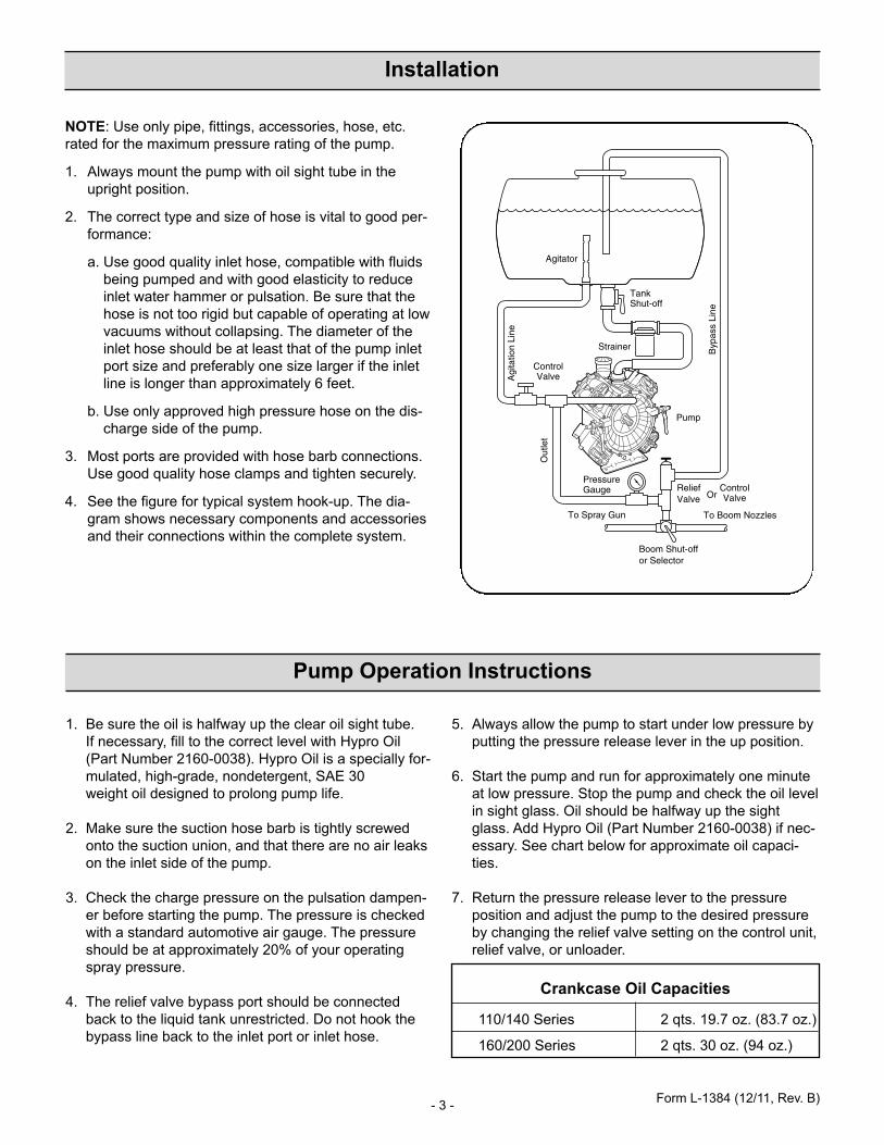
a. Use good quality inlet hose, compatible with fluidsbeing pumped and with good elasticity to reduceinlet water hammer or pulsation. Be sure that thehose is not too rigid but capable of operating at lowvacuums without collapsing. The diameter of theinlet hose should be at least that of the pump inletport size and preferably one size larger if the inletline is longer than approximately 6 feet.
b. Use only approved high pressure hose on the dis-charge side of the pump.
3. Most ports are provided with hose barb connections.Use good quality hose clamps and tighten securely.
4. See the figure for typical system hook-up. The dia-gram shows necessary components and accessoriesand their connections within the complete system.
Agi
tatio
nLi
ne
Out
let
Control Valve
Control Valve
Or
Pressure Gauge
To Spray Gun
To Boom Nozzles
Byp
ass
Line
Tank Shut-off
Strainer
Relief Valve
Pump
Boom Shut-off or Selector
Agitator
Pump Operation Instructions
1. Be sure the oil is halfway up the clear oil sight tube. If necessary, fill to the correct level with Hypro Oil(Part Number 2160-0038). Hypro Oil is a specially for-mulated, high-grade, nondetergent, SAE 30 weight oil designed to prolong pump life.
2. Make sure the suction hose barb is tightly screwedonto the suction union, and that there are no air leakson the inlet side of the pump.
3. Check the charge pressure on the pulsation dampen-er before starting the pump. The pressure is checkedwith a standard automotive air gauge. The pressureshould be at approximately 20% of your operatingspray pressure.
4. The relief valve bypass port should be connectedback to the liquid tank unrestricted. Do not hook thebypass line back to the inlet port or inlet hose.
5. Always allow the pump to start under low pressure byputting the pressure release lever in the up position.
6. Start the pump and run for approximately one minuteat low pressure. Stop the pump and check the oil levelin sight glass. Oil should be halfway up the sightglass. Add Hypro Oil (Part Number 2160-0038) if nec-essary. See chart below for approximate oil capaci-ties.
7. Return the pressure release lever to the pressureposition and adjust the pump to the desired pressureby changing the relief valve setting on the control unit,relief valve, or unloader.
Crankcase Oil Capacities
110/140 Series 2 qts. 19.7 oz. (83.7 oz.)
160/200 Series 2 qts. 30 oz. (94 oz.)
Form L-1384 (12/11, Rev. B)
- 4 -
Troubleshooting
Symptom
The pump does not draw water.
The liquid flow is irregular.
Output drops and the pump is noisy.
Oil comes out of the discharge portor oil is a milky color.
Probable Cause(s)
One or more valves are seatingimproperly.
Suction line is plugged or col-lapsed. Clogged strainer.
The charge in the pulsationdamper is incorrect.
One or more valves are seatingimproperly.
Oil level is too low.
One or more diaphragms split.
Corrective Action
Remove valve and check for debris.
Examine suction line. Clean strainer.
Check pressure in pulsation damper(approximately 20% of your operat-ing spray pressure).
Remove valve and check for debris.Examine the valve seatings andclean them.
Add oil to correct level (halfway upthe sight tube).
Remove manifold and heads. Drainoil and clean crankcase of water.Replace diaphragms, heads andmanifold. Refill with Hypro Oil (PartNo. 2160-0038).
• Always drain and flush pump before servicing or disassembling for any reason (see instructions).
• Always drain and flush pump prior to returning unit for repair.
• Never store pumps containing hazardous chemicals.
• Before returning pump for service/repair, drain out all liquids and flush unit with neutralizing liquid. Then, drain the pump. Attach tag or include written notice certifying that this has been done. Please note that it is illegal to ship or transport any hazardous chemicals without United States Environmental Protection Agency Licensing.
Hazardous Substance Alert
Maintenance Schedule
Form L-1384 (12/11, Rev. B)
- 5 -
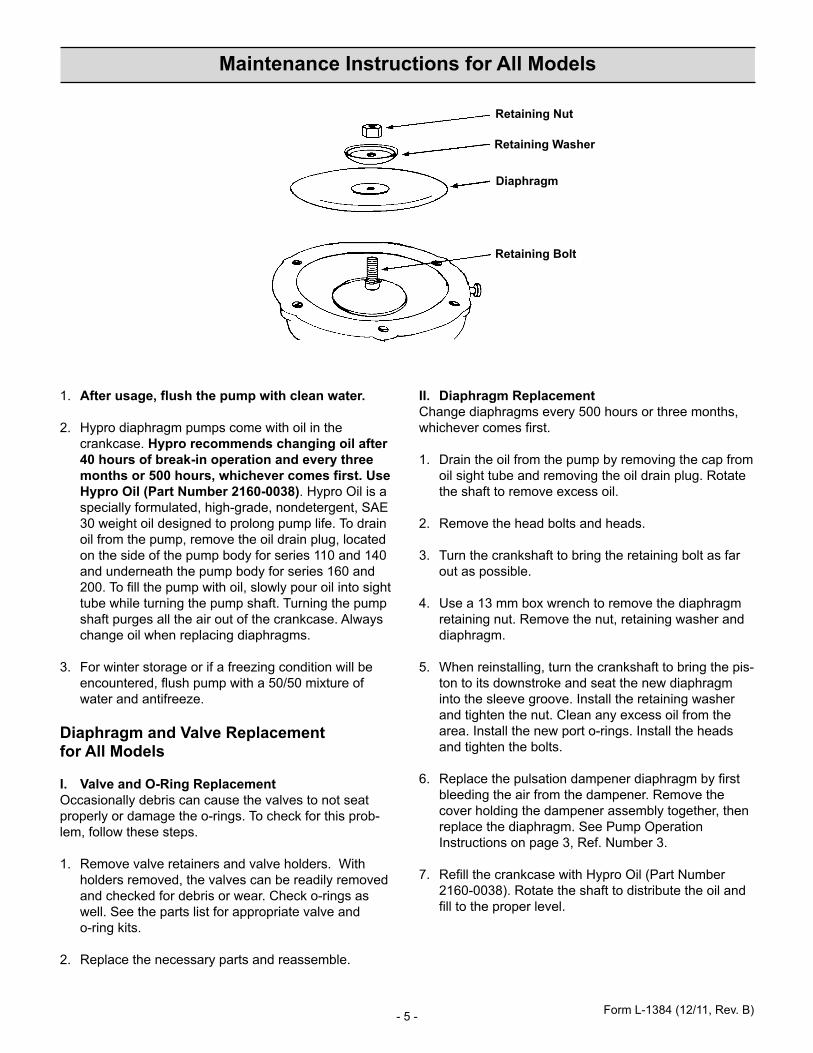
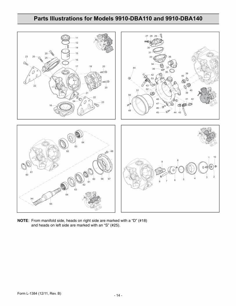
Maintenance Instructions for All Models
Form L-1384 (12/11, Rev. B)
Retaining Nut
Retaining Washer
Diaphragm
Retaining Bolt
1. After usage, flush the pump with clean water.
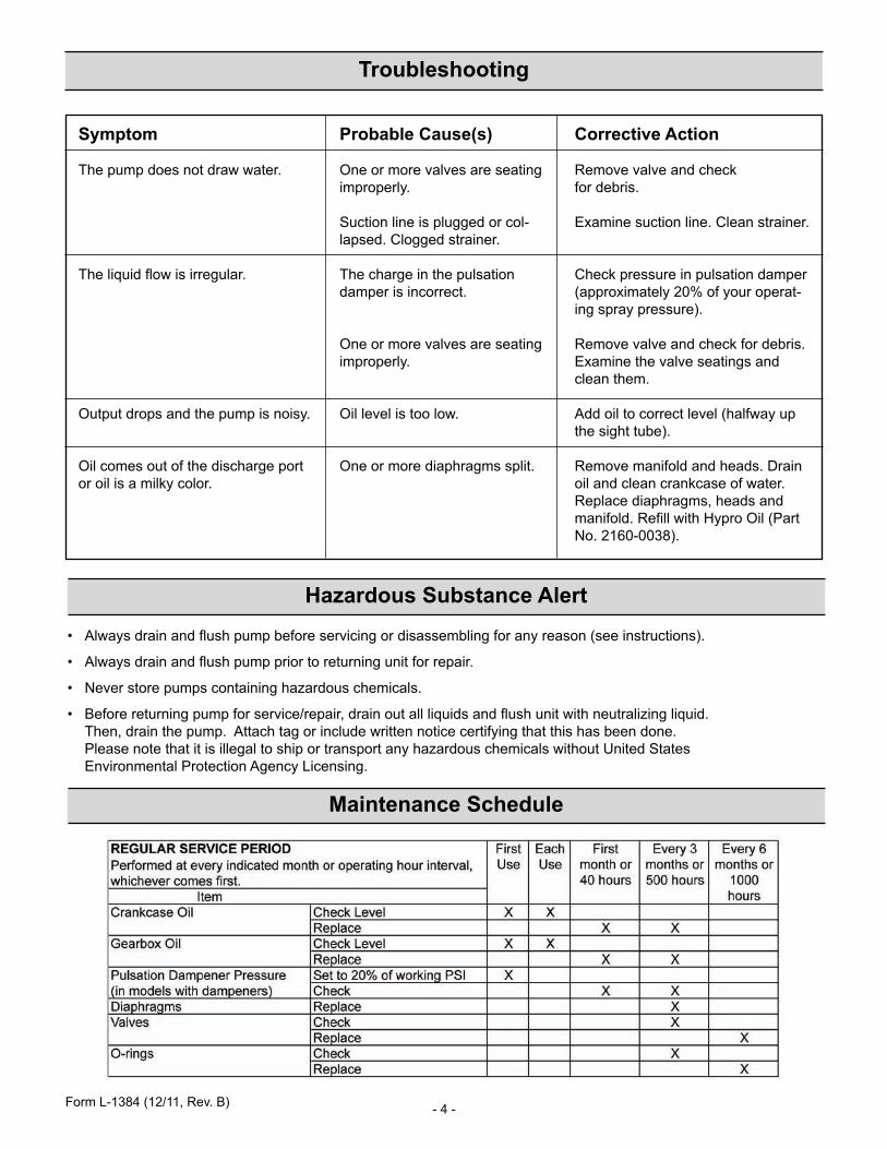
2. Hypro diaphragm pumps come with oil in thecrankcase. Hypro recommends changing oil after40 hours of break-in operation and every threemonths or 500 hours, whichever comes first. UseHypro Oil (Part Number 2160-0038). Hypro Oil is aspecially formulated, high-grade, nondetergent, SAE30 weight oil designed to prolong pump life. To drainoil from the pump, remove the oil drain plug, locatedon the side of the pump body for series 110 and 140and underneath the pump body for series 160 and200. To fill the pump with oil, slowly pour oil into sighttube while turning the pump shaft. Turning the pumpshaft purges all the air out of the crankcase. Alwayschange oil when replacing diaphragms.
3. For winter storage or if a freezing condition will beencountered, flush pump with a 50/50 mixture ofwater and antifreeze.
Diaphragm and Valve Replacement for All Models
I. Valve and O-Ring ReplacementOccasionally debris can cause the valves to not seatproperly or damage the o-rings. To check for this prob-lem, follow these steps.
1. Remove valve retainers and valve holders. Withholders removed, the valves can be readily removedand checked for debris or wear. Check o-rings aswell. See the parts list for appropriate valve and o-ring kits.
2. Replace the necessary parts and reassemble.
II. Diaphragm Replacement Change diaphragms every 500 hours or three months,whichever comes first.
1. Drain the oil from the pump by removing the cap fromoil sight tube and removing the oil drain plug. Rotatethe shaft to remove excess oil.
2. Remove the head bolts and heads.
3. Turn the crankshaft to bring the retaining bolt as farout as possible.
4. Use a 13 mm box wrench to remove the diaphragmretaining nut. Remove the nut, retaining washer anddiaphragm.
5. When reinstalling, turn the crankshaft to bring the pis-ton to its downstroke and seat the new diaphragminto the sleeve groove. Install the retaining washerand tighten the nut. Clean any excess oil from thearea. Install the new port o-rings. Install the headsand tighten the bolts.
6. Replace the pulsation dampener diaphragm by firstbleeding the air from the dampener. Remove thecover holding the dampener assembly together, thenreplace the diaphragm. See Pump OperationInstructions on page 3, Ref. Number 3.
7. Refill the crankcase with Hypro Oil (Part Number2160-0038). Rotate the shaft to distribute the oil andfill to the proper level.
- 6 -
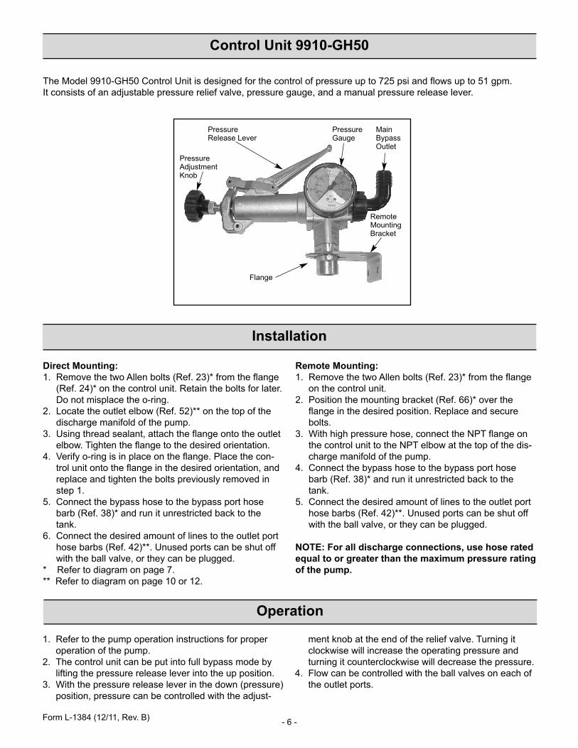
Control Unit 9910-GH50
The Model 9910-GH50 Control Unit is designed for the control of pressure up to 725 psi and flows up to 51 gpm. It consists of an adjustable pressure relief valve, pressure gauge, and a manual pressure release lever.
Installation
Direct Mounting:1. Remove the two Allen bolts (Ref. 23)* from the flange
(Ref. 24)* on the control unit. Retain the bolts for later.Do not misplace the o-ring.
2. Locate the outlet elbow (Ref. 52)** on the top of thedischarge manifold of the pump.
3. Using thread sealant, attach the flange onto the outletelbow. Tighten the flange to the desired orientation.
4. Verify o-ring is in place on the flange. Place the con-trol unit onto the flange in the desired orientation, andreplace and tighten the bolts previously removed instep 1.
5. Connect the bypass hose to the bypass port hosebarb (Ref. 38)* and run it unrestricted back to thetank.
6. Connect the desired amount of lines to the outlet porthose barbs (Ref. 42)**. Unused ports can be shut offwith the ball valve, or they can be plugged.
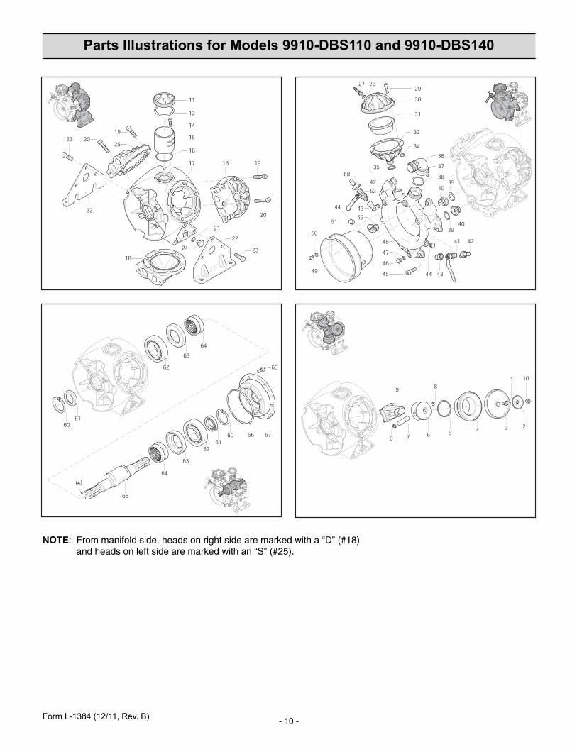
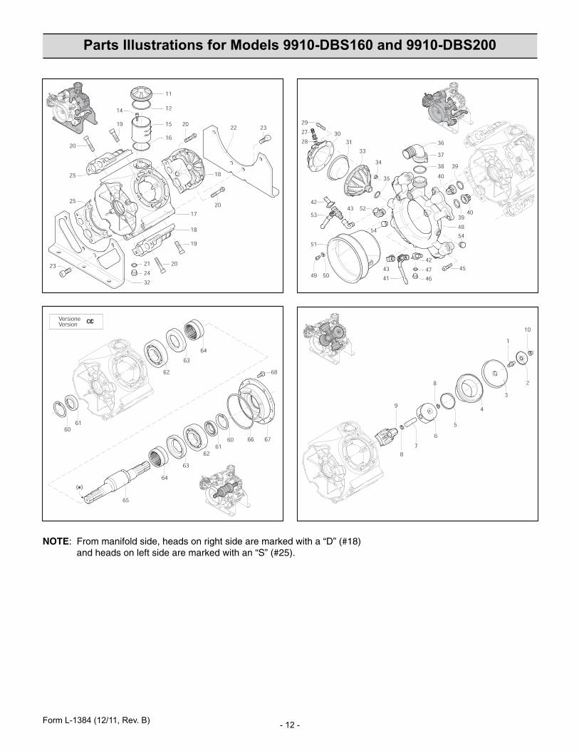
* Refer to diagram on page 7.** Refer to diagram on page 10 or 12.
Remote Mounting:1. Remove the two Allen bolts (Ref. 23)* from the flange
on the control unit.2. Position the mounting bracket (Ref. 66)* over the
flange in the desired position. Replace and securebolts.
3. With high pressure hose, connect the NPT flange onthe control unit to the NPT elbow at the top of the dis-charge manifold of the pump.
4. Connect the bypass hose to the bypass port hosebarb (Ref. 38)* and run it unrestricted back to thetank.
5. Connect the desired amount of lines to the outlet porthose barbs (Ref. 42)**. Unused ports can be shut offwith the ball valve, or they can be plugged.
NOTE: For all discharge connections, use hose ratedequal to or greater than the maximum pressure ratingof the pump.
Operation
1. Refer to the pump operation instructions for properoperation of the pump.
2. The control unit can be put into full bypass mode bylifting the pressure release lever into the up position.
3. With the pressure release lever in the down (pressure)position, pressure can be controlled with the adjust-
ment knob at the end of the relief valve. Turning itclockwise will increase the operating pressure andturning it counterclockwise will decrease the pressure.
4. Flow can be controlled with the ball valves on each ofthe outlet ports.
Pressure Release Lever
Pressure Gauge
MainBypassOutlet
Remote MountingBracket
Flange
Pressure AdjustmentKnob
Form L-1384 (12/11, Rev. B)
- 7 -
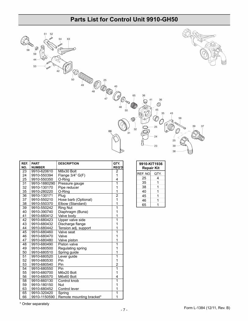
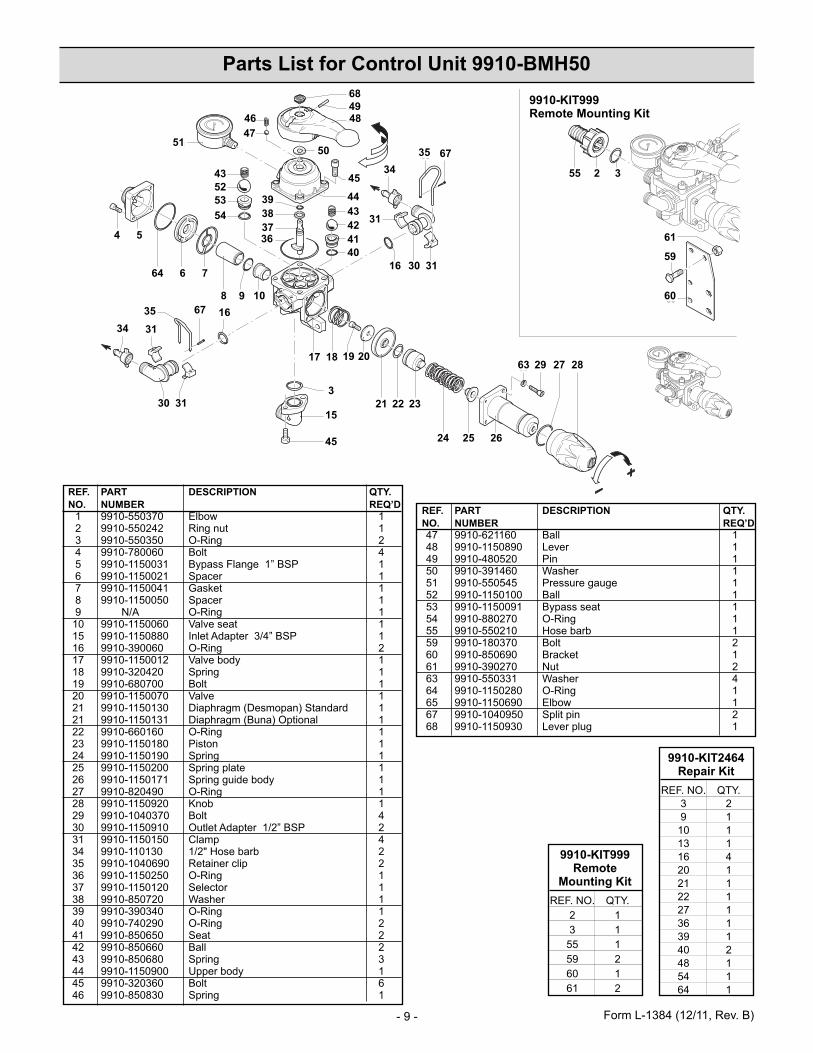
Parts List for Control Unit 9910-GH50
REF. PART DESCRIPTION QTY. NO. NUMBER REQ’D23 9910-620610 Bolt 224 9910-550394 Flange 3/4” G(F) 125 9910-550350 O-Ring 431 9910-1880290 Pressure gauge 132 9910-130170 Pipe reducer 135 9910-280220 O-Ring 136 9910-130171 Plug 237 9910-550210 Hose barb (Optional) 138 9910-550370 Elbow (Standard) 139 9910-550242 Ring Nut 140 9910-390740 Diaphragm (Buna) 141 9910-680412 Valve body 142 9910-680423 Upper valve side 143 9910-680432 Discharge flange 144 9910-680442 Tension adj. support 145 9910-680460 Valve seat 146 9910-680470 Valve 147 9910-680480 Valve piston 148 9910-680490 Piston valve 149 9910-680500 Regulating spring 150 9910-680510 Spring guide 151 9910-680520 Lever guide 152 9910-680530 Pin 153 9910-680540 Pin 254 9910-680550 Pin 155 9910-680700 Bolt 156 9910-680570 Bolt 458 9910-660130 Control knob 159 9910-180150 Nut 163 9910-680452 Control lever 165 9910-320420 Spring 166 9910-1150590 Remote mounting bracket* 1
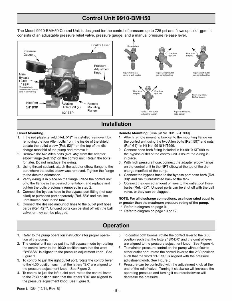
The Model 9910-BMH50 Control Unit is designed for the control of pressure up to 725 psi and flows up to 41 gpm. Itconsists of an adjustable pressure relief valve, pressure gauge, and a manual pressure release lever.
InstallationDirect Mounting:1. If the red plastic shield (Ref. 51)** is installed, remove it by
removing the four Allen bolts from the inside of the shield.Locate the outlet elbow (Ref. 52)** on the top of the dis-charge manifold of the pump and remove it.
2. Remove the two Allen bolts (Ref. 45)* from the adapterelbow flange (Ref.15)* on the control unit. Retain the boltsfor later. Do not misplace the o-ring.
3. Using thread sealant, attach the adapter elbow flange to theport where the outlet elbow was removed. Tighten the flangeto the desired orientation.
4. Verify o-ring is in place on the flange. Place the control unitonto the flange in the desired orientation, and replace andtighten the bolts previously removed in step 2.
5. Connect the bypass hose to the bypass port fitting (not sup-plied) or purchase part separately (Ref. 55)* and run lineunrestricted back to the tank.
6. Connect the desired amount of lines to the outlet port hosebarbs (Ref. 42)**. Unused ports can be shut off with the ballvalve, or they can be plugged.
Remote Mounting: (Use Kit No. 9910-KIT999)1. Attach remote mounting bracket to the mounting flange on
the control unit using the two Allen bolts (Ref. 59)* and nuts(Ref. 61)* in Kit No. 9910-KIT999.
2. Connect hose barb fitting included in Kit 9910-KIT999 to the bypass outlet of the control unit. Ensure the o-ring is in place.
3. With high pressure hose, connect the adapter elbow flangeon the control unit to the NPT elbow at the top of the dis-charge manifold of the pump.
4. Connect the bypass hose to the bypass port hose barb (Ref.38)* and run it unrestricted back to the tank.
5. Connect the desired amount of lines to the outlet port hosebarbs (Ref. 42)**. Unused ports can be shut off with the ballvalve, or they can be plugged.
NOTE: For all discharge connections, use hose rated equal toor greater than the maximum pressure rating of the pump.
* Refer to diagram on page 9.** Refer to diagram on page 10 or 12.
Operation1. Refer to the pump operation instructions for proper opera-
tion of the pump.2. The control unit can be put into full bypass mode by rotating
the control lever to the 10:30 position such that the word“BYPASS” is aligned to the pressure adjustment knob. SeeFigure 1.
3. To control to just the right outlet port, rotate the control leverto the 4:30 position such that the letters “SX” are aligned tothe pressure adjustment knob. See Figure 2.
4. To control to just the left outlet port, rotate the control leverto the 7:30 position such that the letters “DX” are aligned tothe pressure adjustment knob. See Figure 3.
5. To control both booms, rotate the control lever to the 6:00position such that the letters “SX-DX” and the control leverare aligned to the pressure adjustment knob. See Figure 4.
6. To maintain pressure control on the pump without flow toeither outlet port, rotate the control lever to the 2:30 positionsuch that the word “PRESS” is aligned with the pressureadjustment knob. See Figure 5.
7. Pressure can be controlled with the adjustment knob at theend of the relief valve. Turning it clockwise will increase theoperating pressure and turning it counterclockwise willdecrease the pressure.
Pressure Gauge
Main Bypass Outlet1” BSP(Connect directly to tank without restric-tions or ball valves.)
Hypro/SHURflo (hereafter, “Hypro”) agricultural products are warranted to be free of defects in material and workmanship undernormal use for the time periods listed below, with proof of purchase.
- Pumps: one (1) year from the date of manufacture, or one (1) year of use. This limited warranty will notexceed two (2) years, in any event.
- Accessories: ninety (90) days of use.
This limited warranty will not apply to products that were improperly installed, misapplied, damaged, altered, or incompatible withfluids or components not manufactured by Hypro. All warranty considerations are governed by Hypro’s written return policy.
Hypro’s obligation under this limited warranty policy is limited to the repair or replacement of the product. All returns will be testedper Hypro’s factory criteria. Products found not defective (under the terms of this limited warranty) are subject to charges paid by thereturnee for the testing and packaging of “tested good” non-warranty returns.
No credit or labor allowances will be given for products returned as defective. Warranty replacement will be shipped on a freight allowedbasis. Hypro reserves the right to choose the method of transportation.
This limited warranty is in lieu of all other warranties, expressed or implied, and no other person is authorized to give any otherwarranty or assume obligation or liability on Hypro’s behalf. Hypro shall not be liable for any labor, damage or other expense, nor shallHypro be liable for any indirect, incidental or consequential damages of any kind incurred by the reason of the use or sale ofany defective product. This limited warranty covers agricultural products distributed within the United States of America. Other worldmarket areas should consult with the actual distributor for any deviation from this document.
Return ProceduresAll products must be flushed of any chemical (ref. OSHA section 1910.1200 (d) (e) (f) (g) (h)) and hazardous chemicals must belabeled/tagged before being shipped* to Hypro for service or warranty consideration. Hypro reserves the right to request a MaterialSafety Data Sheet from the returnee for any pump/product it deems necessary. Hypro reserves the right to “disposition as scrap” products returned which contain unknown fluids. Hypro reserves the right to charge the returnee for any and all costs incurred for chemical testing, and proper disposal of components containing unknown fluids. Hypro requests this in order to protect the environmentand personnel from the hazards of handling unknown fluids.
Be prepared to give Hypro full details of the problem, including the model number, date of purchase, and from whom you purchasedyour product. Hypro may request additional information, and may require a sketch to illustrate the problem.
Contact Hypro Service Department at 800-468-3428 to receive a Return Merchandise Authorization number (RMA#).Returns are to be shipped with the RMA number clearly marked on the outside of the package. Hypro shall not be liable for freightdamage incurred during shipping. Please package all returns carefully. All products returned for warranty work should be sent shipping charges prepaid to:
HYPROAttention: Service Department375 Fifth Avenue NWNew Brighton, MN 55112
For technical or application assistance, call the Hypro Technical/Application number: 800-445-8360, or send an email to:[email protected]. To obtain service or warranty assistance, call the Hypro Service and Warranty number:800-468-3428; or send a fax to the Hypro Service and Warranty FAX: 651-766-6618.
*Carriers, including U.S.P.S., airlines, UPS, ground freight, etc., require specific identification of any hazardous material being shipped. Failure to do somay result in a substantial fine and/or prison term. Check with your shipping company for specific instructions.
Limited Warranty on Hypro/SHURflo Agricultural Pumps & Accessories