_L . UCRLJC-UOl58 PREPRINT , .. PEP-I11 Magnet Power Conversion Systems:. Power Supplies for Lmge Magnet Strings T. Jackson, A. Saab, And D. Shimer This paper was prepared for submifbl to the IEEE 1995 Pvticle Accelerator Conference and Mernah ‘onal Conference on High-Energy Accelerators Dallas,Texas May 1-5,1995 . May1995 Thbbrprc~tof8prpahtended forpubliationinrjorpdhga Sha dunp nuy be nude before pabliath, thii preprint ir made available with the undurbnding that it will not be cited ar n@ud withoat the permk of the I 8UthCU. .. ..
Transcript
_L .
UCRLJC-UOl58 PREPRINT
,
. . PEP-I11 Magnet Power Conversion Systems:. Power Supplies for Lmge Magnet Strings
T. Jackson, A. Saab, And D. Shimer
This paper was prepared for submifbl to the IEEE
1995 Pvticle Accelerator Conference and Mernah ‘onal Conference on High-Energy Accelerators
Dallas,Texas May 1-5,1995
. May1995
Thbbrprc~tof8prpahtended f o r p u b l i a t i o n i n r j o r p d h g a S h a dunp nuy be nude before pabliath, thii preprint ir made available with the undurbnding that it will not be cited ar n @ u d withoat the p e r m k of the
I 8UthCU. . . . .
DISCLAIMER
This report was prepared as an account of work sponsored by an agency of the United States Government. Neither the United States Government nor any agency thereof, nor any of their employees, make any warranty, express or implied, or assumes any legal liability or responsibility for the accuracy, completeness, or usefulness of any information, apparatus, product, or process disclosed, or represents that its use would not infringe privately owned rights. Reference herein to any specific commercial product, process, or service by trade name, trademark, manufacturer, or otherwise does not necessarily constitute or imply its endorsement, recommendation, or favoring by the United States Government or any agency thereof. The views and opinions of authors expressed herein do not necessarily state or reflect those of the United States Government or
. any agency thereof.
DISCLAIMER
Portions of this document may be illegible in electronic image products. Images are produced from the best available original document.
I
1 I '
. . . . . . Abstract
PEP-I11 Magnet Power Conversion Systems: Power Supplies for Large Magnet Strings
T. JACKSON, Lawrence Berkeley Laboratory, A. SAAB, Stanford Linear Accelerator Center, and D. SHIMER, Lawrence Livermore National Laboratory
This paper presents the cooperative design efforts of LBL, SLAC, and LLNL on the magnet power conversion systems for PEP-II. The systems include 900 channels of correction magnet bipolar supplies and 400 unipolar supplies in the range of 5 to 500 kW. We show the decision process and technical considerations influencing the choice of power supply technologies employed. We also show the development of specifications that take maximum advantage of both the resources available and existing facilities while at the same time satisfying tight constraints for cost control, scheduling, and coordination of different working groups. Switch-mode power conversion techniques will be used extensively in these systems, from the corrector supplies to the largest units if the dynamic performance specifications demand it. General system desaiptions for each of the power supply ranges and for a new common control system interface and regulator are iizcluded.
* I Supported by the U.S. Department of Energy, under Contract Numbers DE-AC03-76SF00098 (LBL), DE-ACO3-76SFOO515 (SLAC), and W-7405-Eng-48 (LLNL]. .
MASTER DISTRIBUTION OF THIS DOCUMENT IS UNLIMITED/
for L a r g e t S t n m
PEP 11 has twenty-one circuits of series-connected magnets in the two rings. The HER has sixteen circuits and the LER has five circuits. The magnets in these circuits are the bend dipole magnets, the focus and defocus quadrupole magnets, the focus and defocus sextupole magnets, and several sets of special quadrupole magnets. The total power for the HER and LER string magnet circuits at their maximum operating point is 4300 kW. It divides between the HER strings at 2400 kW (56 8) and the LER strings at 1900 k W (44 910). The largest strings contain the HER and LER bend dipole magnets which each contain 192 and 200 magnets, respectively.
that of PEP I - a large bulk dc power supply driving several individual buck-type dc-dc converters, or choppers, for each string (Fig. 1). The bulk power supplies consist of two transformers with associated switchgear and half-controlled rectifiers. The rectifiers produce positive and negative 600 Vdc sources for the individual string circuit dc-dc converters. Controlled rectifiers are used to provide low inrush currents and fast fault protection. The current control for each magnet string is done in the dc-dc converters. Separate circuit breakers and rectifiers are used for the HER and LER strings for operational flexibility. Much of the old equipment from PEP I, including the transformers, racks, ac cabling, and dc cabling, will be refurbished and reused. The dc-dc converters will be changed from a forced-commutated design using thyristors to one using insulated-gate-bipolar transistors (IGBTs). They are being designed as 200 kW modules which can be connected in series and in parallel, but are not hot-swappable. They will contain extensive differential and common-mode filtering. The instrumentation and controls will be modernized using new transductors and imbedded computers.
400 A or 0 to - 500 Vdc at 400 A. The maximum voltage available to power a magnet string is loo0 Vdc which is achieved by using positive and negative dc-dc converter modules in series. Magnet strings which require more than lo00 Vdc must be divided into smaller lengths. The HER bend magnet string requires three modules in parallel to achieve the required 890 A. It also must be divided into two strings of 96 magnets and 690 V each in order to not exceed the lo00 V limit. This circuit requires a total of 12 dc- dc converter modules. The LER bend magnet string also requires splitting and has two strings of 100 magnets at 745 A and 990 V each. Eight dc-dc converter modules are used. Four of the main quadrupole strings have currents below 400 A but require two
The power supply architecture for the large magnet strings in PEP 11 is very similar to
The dc-dc converter modules are designed to have outputs of either 0 to + 500 Vdc at
modules each because the voltages are above 500 V. The remaining 15 circuits require only one module since the currents are all below 400 A and the voltages are below 500 V.
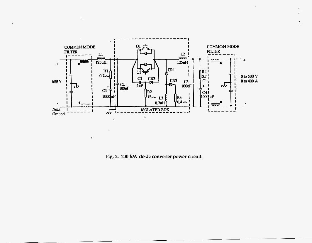
The power circuit of the dc-dc converter module is shown in Fig. 2. Two 600 A, 1200 V IGBTs are alternately gated at 10 lcHz for an effective 20 lcHz internal frequency. Snubber networks are used to reduce turnon switching losses in the IGBTs and to clamp
the voltage across the IGBTs during turnoff. The IGBTs and diodes are mounted on a water-cooled aluminum heat sink. The "box-in-box" construction and the common-mode filters at the input and output control EMI. The IGBTs are controlled using commercial gate drivers modified for fiber optics, and a commercial current-mode PWM controller integrated circuit. The ordoff duty cycle of the IGBTs varies to regulate the average output voltage in response to a voltage setpoint. Current feedback for the nested current loop is from a closed-loop Hall effect current sensor on the output filter inductor. The voltage setpoint is received from the SLAC current controller and is a function of the current demand and the feedback from the power supply output current transductor.
The string magnet power supplies are nearing the end of the preliminary design phase. A "breadboard" version of the dc-dc converter power circuit has operated successfully into a resistive load at 200 k W while under open-loop control.