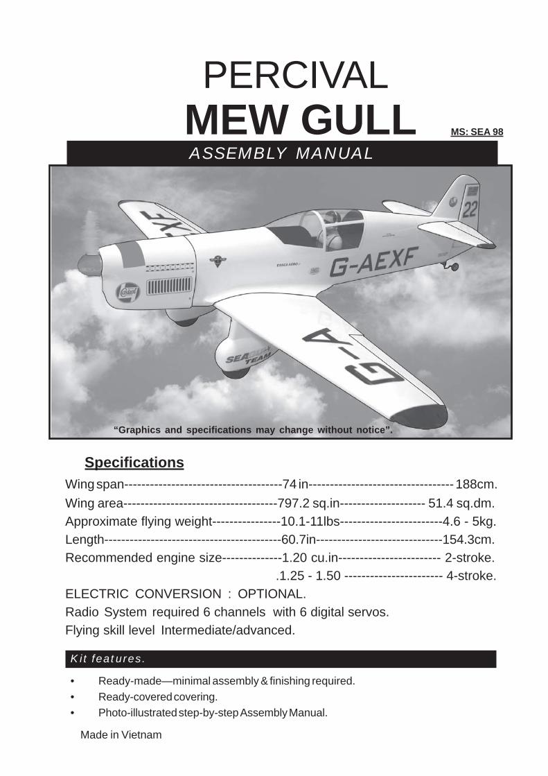
“Graphics and specifications may change without notice”.
ASSEMBLY MANUALMS: SEA 98
PERCIVAL
PERCIVAL MEW GULL Instruction Manual
2
INTRODUCTION.
Thank you for choosing the PERCIVAL MEW GULL ARTF by SEAGULL MODELS. ThePERCIVAL MEW GULL was designed with the intermediate/advanced sport scale in mind. It is asemi scale airplane which is easy to fly and quick to assemble. The airframe is conventionally builtusing balsa, plywood to make it stronger than the average ARTF , yet the design allows the aeroplaneto be kept light. You will find that most of the work has been done for you already. The motor mounthas been fitted and the hinges are pre-installed . Flying the PERCIVAL MEW GULL is simply a joy.
This instruction manual is designed to help you build a great flying aeroplane. Please read thismanual thoroughly before starting assembly of your PERCIVAL MEW GULL. Use the parts listingbelow to identify all parts.
WARNING.
Please be aware that this aeroplane is not a toy and if assembled or used incorrectly itis capable of causing injury to people or property. WHEN YOU FLY THIS AEROPLANE YOUASSUME ALL RISK & RESPONSIBILITY. If you are inexperienced with basic R/C flight we strongly recommend you contact your R/Csupplier and join your local R/C Model Flying Club. R/C Model Flying Clubs offer a variety of trainingprocedures designed to help the new pilot on his way to successful R/C flight. They will also be ableto advise on any insurance and safety regulations that may apply.
Radio System required 6 channelswith 6 digital servos
Propeller to suit engineProtective foam rubber for radiosystemSilicone fuel line
TOOLS & SUPPLIES NEEDED.
Thick cyanoacrylate glue30 minute epoxy5 minute epoxyHand or electric drillAssorted drill bitsModelling knifeStraight edge ruler2mm ball driverPhillips head screwdriver220 grit sandpaper90° square or builder’s triangleWire cuttersMasking tape & T-pinsThread-lockPaper towels
PARTS LISTING.
FUSELAGE ASSEMBLY(1) Fuselage(1) Canopy
WING ASSEMBLY
(1) Right wing half/ aileron(1) Left wing half with/ aileron(1) Aluminium dihedral brace
Tail section assembly
(1) Horizontal stabilizer/ elevatorhalves.
(1) Rudder halves.
Some more parts.
HARDWARE PACK
COWLINGLanding gear.....
www.seagullmodels.com
3
1) Carefully remove the aileron from one ofthe wing panels. Note the position of the hinges.
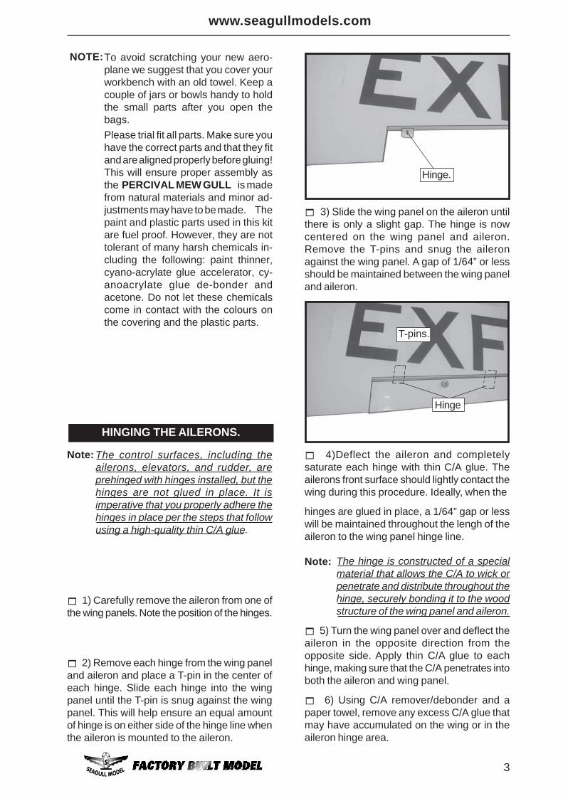
2) Remove each hinge from the wing paneland aileron and place a T-pin in the center ofeach hinge. Slide each hinge into the wingpanel until the T-pin is snug against the wingpanel. This will help ensure an equal amountof hinge is on either side of the hinge line whenthe aileron is mounted to the aileron.
3) Slide the wing panel on the aileron untilthere is only a slight gap. The hinge is nowcentered on the wing panel and aileron.Remove the T-pins and snug the aileronagainst the wing panel. A gap of 1/64” or lessshould be maintained between the wing paneland aileron.
The control surfaces, including theailerons, elevators, and rudder, areprehinged with hinges installed, but thehinges are not glued in place. It isimperative that you properly adhere thehinges in place per the steps that followusing a high-quality thin C/A glue.
Note: 4)Deflect the aileron and completelysaturate each hinge with thin C/A glue. Theailerons front surface should lightly contact thewing during this procedure. Ideally, when the
To avoid scratching your new aero-plane we suggest that you cover yourworkbench with an old towel. Keep acouple of jars or bowls handy to holdthe small parts after you open thebags.Please trial fit all parts. Make sure youhave the correct parts and that they fitand are aligned properly before gluing!This will ensure proper assembly asthe PERCIVAL MEW GULL is madefrom natural materials and minor ad-justments may have to be made. Thepaint and plastic parts used in this kitare fuel proof. However, they are nottolerant of many harsh chemicals in-cluding the following: paint thinner,cyano-acrylate glue accelerator, cy-anoacrylate glue de-bonder andacetone. Do not let these chemicalscome in contact with the colours onthe covering and the plastic parts.
NOTE:
HINGING THE AILERONS.
5) Turn the wing panel over and deflect theaileron in the opposite direction from theopposite side. Apply thin C/A glue to eachhinge, making sure that the C/A penetrates intoboth the aileron and wing panel.
6) Using C/A remover/debonder and apaper towel, remove any excess C/A glue thatmay have accumulated on the wing or in theaileron hinge area.
Hinge.
Hinge
T-pins.
hinges are glued in place, a 1/64” gap or lesswill be maintained throughout the lengh of theaileron to the wing panel hinge line.
Note: The hinge is constructed of a specialmaterial that allows the C/A to wick orpenetrate and distribute throughout thehinge, securely bonding it to the woodstructure of the wing panel and aileron.
PERCIVAL MEW GULL Instruction Manual
4
HINGING THE ELEVATOR.
8) After both ailerons are securely hinged,firmly grasp the wing panel and aileron tomake sure the hinges are securely glued andcannot be pulled out. Do this by carefullyapplying medium pressure, trying to separatethe aileron from the wing panel. Use cautionnot to crush the wing structure.
7) Repeat this process with the other wingpanel, securely hinging the aileron in place.
HINGING THE RUDDER.
Glue the elevator hinges in place using thesame techniques used to hinge the ailerons.
Glue the rudder hinges in place using thesame techniques used to hinge the ailerons.
Work the aileron up and down severaltimes to “work in” the hinges and checkfor proper movement.
Note:
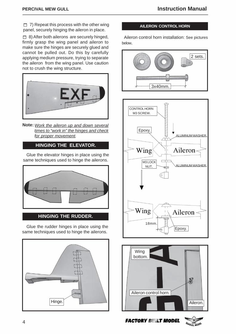
Aileron control horn installation: See picturesbelow.
AILERON CONTROL HORN
Hinge.
2 sets.
3x40mm.
Wingbottom.
M3 LOCK NUT.
ALUMINUM WASHER.
ALUMINUM WASHER.
CONTROL HORN M3 SCREW.
Epoxy.
Epoxy.18mm.
Aileron control horn.
Aileron.
www.seagullmodels.com
5
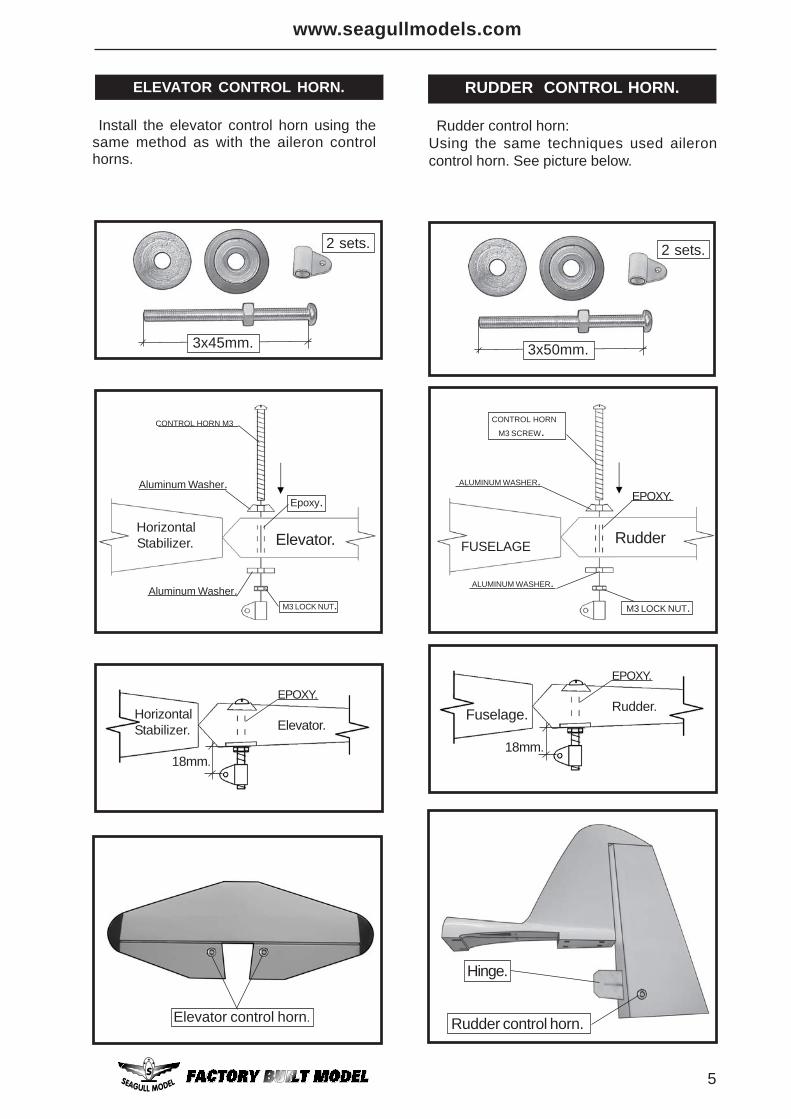
18mm.
EPOXY.
HorizontalStabilizer. Elevator.
ELEVATOR CONTROL HORN.
Install the elevator control horn using thesame method as with the aileron controlhorns.
2 sets.
3x50mm.
CONTROL HORN
M3 SCREW.
ALUMINUM WASHER.
ALUMINUM WASHER.
M3 LOCK NUT.
EPOXY.
FUSELAGE Rudder
2 sets.
3x45mm.
Aluminum Washer.
CONTROL HORN M3
M3 LOCK NUT.
Epoxy.
Aluminum Washer.
Horizontal Stabilizer. Elevator.
18mm.
EPOXY.
Fuselage. Rudder.
Rudder control horn:Using the same techniques used aileroncontrol horn. See picture below.
RUDDER CONTROL HORN.
Elevator control horn.
Hinge.
Rudder control horn.
PERCIVAL MEW GULL Instruction Manual
6
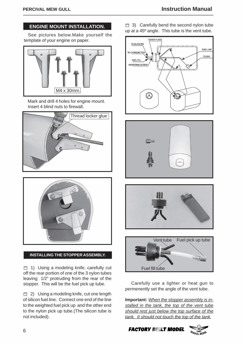
2) Using a modeling knife, cut one lengthof silicon fuel line. Connect one end of the lineto the weighted fuel pick up and the other endto the nylon pick up tube.(The silicon tube isnot included).
1) Using a modeling knife, carefully cutoff the rear portion of one of the 3 nylon tubesleaving 1/2” protruding from the rear of thestopper. This will be the fuel pick up tube.
INSTALLING THE STOPPER ASSEMBLY.
Important: When the stopper assembly is in-stalled in the tank, the top of the vent tubeshould rest just below the top surface of thetank. It should not touch the top of the tank.
Carefully use a lighter or heat gun topermenently set the angle of the vent tube.
See pictures below.Make yourself thetemplate of your engine on paper.
ENGINE MOUNT INSTALLATION.
Mark and drill 4 holes for engine mount. Insert 4 blind nuts to firewall.
M4 x 30mm.
Thread locker glue
3) Carefully bend the second nylon tubeup at a 45º angle. This tube is the vent tube.
Fuel pick up tubeVent tube
Fuel fill tube
www.seagullmodels.com
7
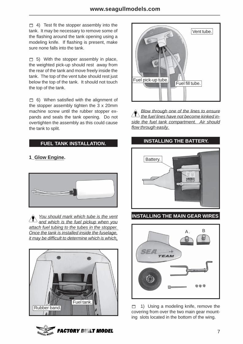
4) Test fit the stopper assembly into thetank. It may be necessary to remove some ofthe flashing around the tank opening using amodeling knife. If flashing is present, makesure none falls into the tank.
5) With the stopper assembly in place,the weighted pick-up should rest away fromthe rear of the tank and move freely inside thetank. The top of the vent tube should rest justbelow the top of the tank. It should not touchthe top of the tank.
6) When satisfied with the alignment ofthe stopper assembly tighten the 3 x 20mmmachine screw until the rubber stopper ex-pands and seals the tank opening. Do notovertighten the assembly as this could causethe tank to split.
FUEL TANK INSTALLATION.
You should mark which tube is the ventand which is the fuel pickup when you
attach fuel tubing to the tubes in the stopper.Once the tank is installed inside the fuselage,it may be difficult to determine which is which.
Rubber band.Fuel tank.
Blow through one of the lines to ensurethe fuel lines have not become kinked in-
side the fuel tank compartment. Air shouldflow through easily.
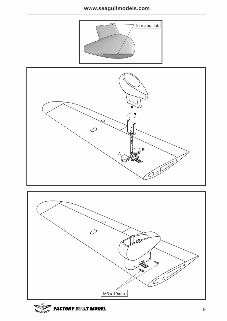
1) Using a modeling knife, remove thecovering from over the two main gear mount-ing slots located in the bottom of the wing.
Vent tube.
Fuel fill tube.Fuel pick-up tube.
A . B
1_Glow Engine.
INSTALLING THE BATTERY.
Battery.
INSTALLING THE MAIN GEAR WIRES
PERCIVAL MEW GULL Instruction Manual
8
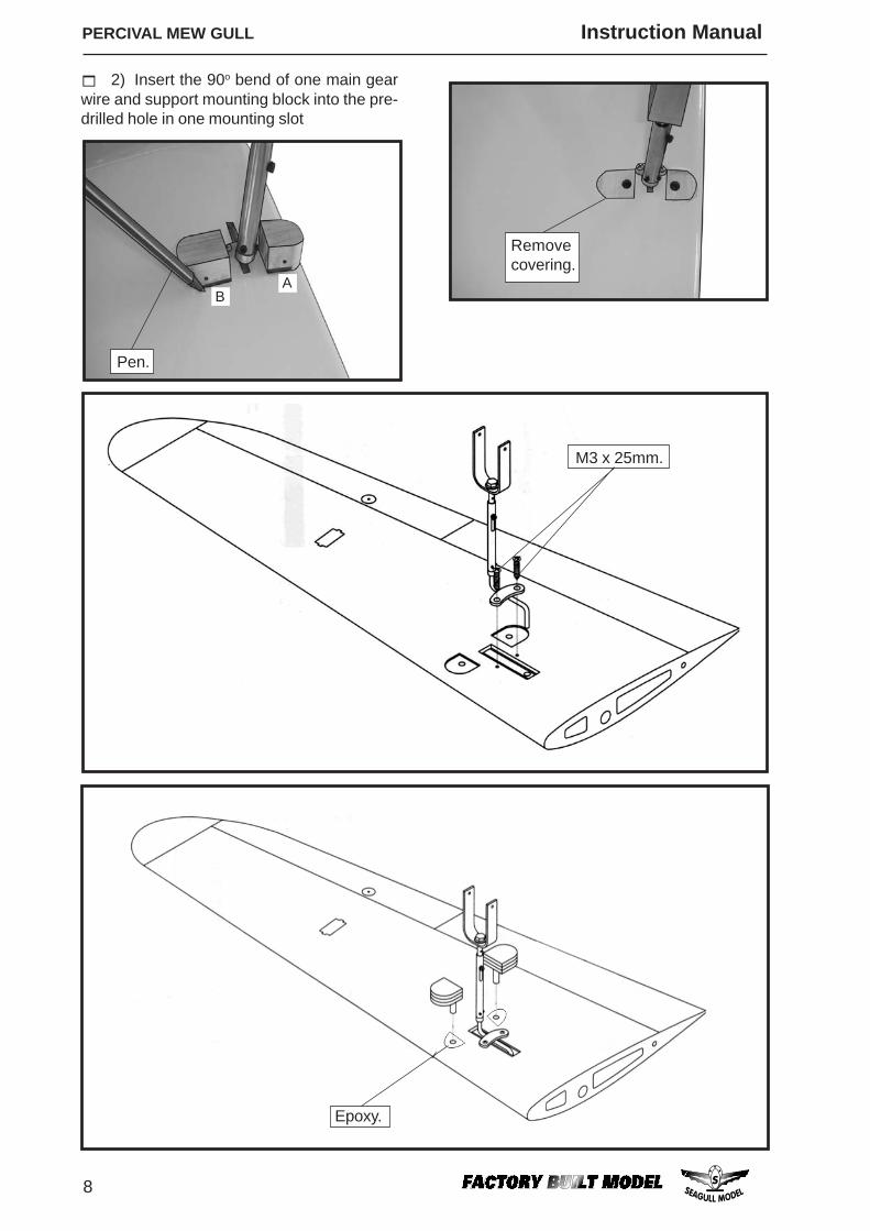
2) Insert the 90o bend of one main gearwire and support mounting block into the pre-drilled hole in one mounting slot
M3 x 25mm.
Epoxy.
Removecovering.
AB
Pen.
www.seagullmodels.com
9
AB
M3 x 10mm.
Trim and cut.
PERCIVAL MEW GULL Instruction Manual
10
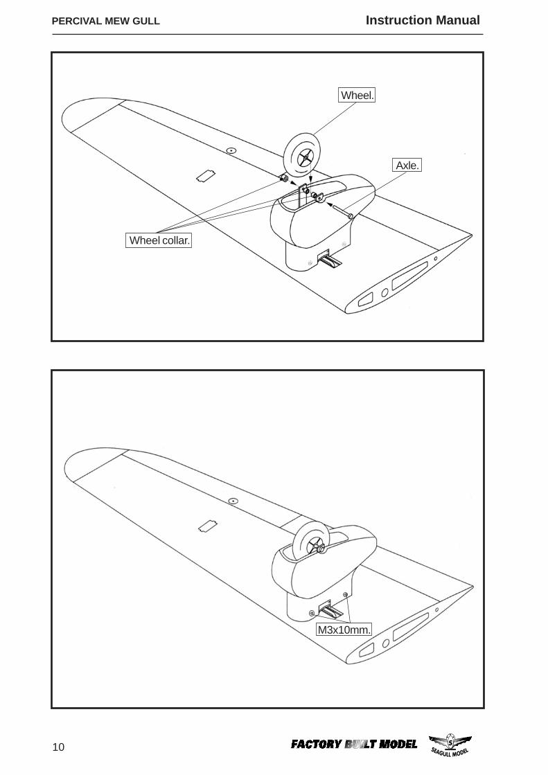
Wheel.
Axle.
M3x10mm.
Wheel collar.
www.seagullmodels.com
11
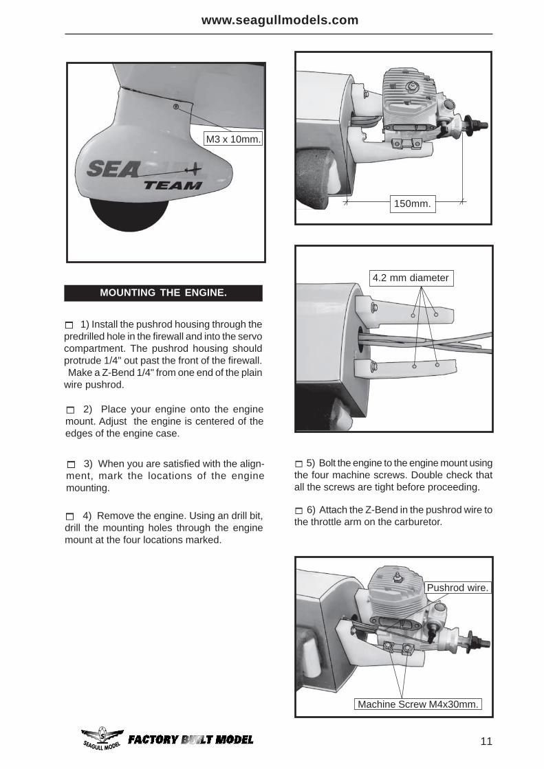
1) Install the pushrod housing through thepredrilled hole in the firewall and into the servocompartment. The pushrod housing shouldprotrude 1/4" out past the front of the firewall. Make a Z-Bend 1/4" from one end of the plainwire pushrod.
MOUNTING THE ENGINE.
6) Attach the Z-Bend in the pushrod wire tothe throttle arm on the carburetor.
5) Bolt the engine to the engine mount usingthe four machine screws. Double check thatall the screws are tight before proceeding.
4) Remove the engine. Using an drill bit,drill the mounting holes through the enginemount at the four locations marked.
2) Place your engine onto the enginemount. Adjust the engine is centered of theedges of the engine case.
3) When you are satisfied with the align-ment, mark the locations of the enginemounting.
M3 x 10mm.
150mm.
4.2 mm diameter
Pushrod wire.
Machine Screw M4x30mm.
PERCIVAL MEW GULL Instruction Manual
12
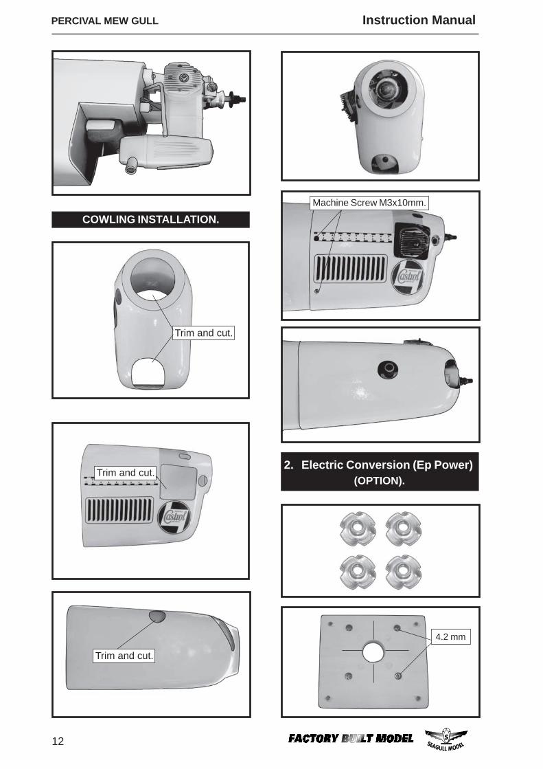
4.2 mm
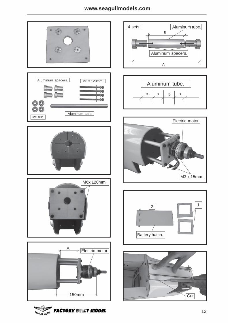
2. Electric Conversion (Ep Power) (OPTION).
COWLING INSTALLATION.
Trim and cut.
Trim and cut.
Trim and cut.
Machine Screw M3x10mm.
www.seagullmodels.com
13
Aluminum tube.
Aluminum spacers. M6 x 120mm.
M5 nut.
M6x 120mm.
Electric motor.
150mm
A
Aluminum spacers.
Aluminum tube.B
A
4 sets.
Aluminum tube.
B B B B
Electric motor.
M3 x 15mm.
12
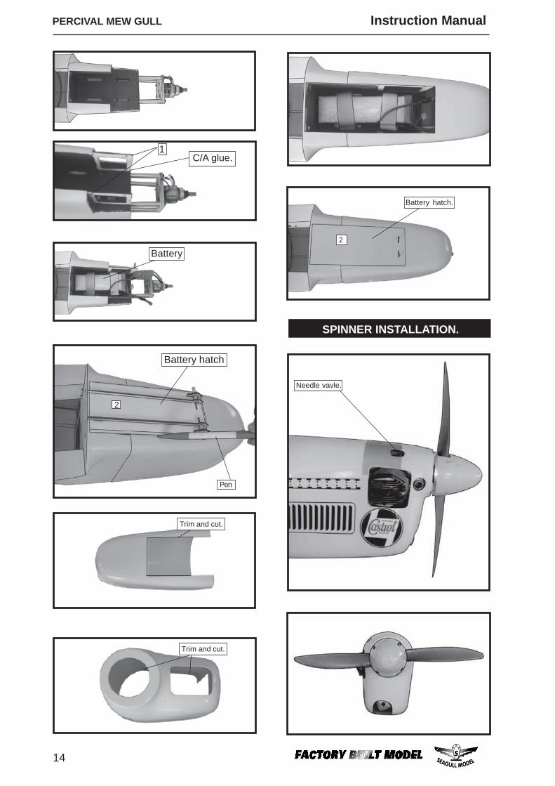
Battery hatch.
Cut
PERCIVAL MEW GULL Instruction Manual
14
Battery hatch
2
Pen
Trim and cut.
Trim and cut.
SPINNER INSTALLATION.
2
Battery hatch.
Needle vavle.
1C/A glue.
Battery
www.seagullmodels.com
15
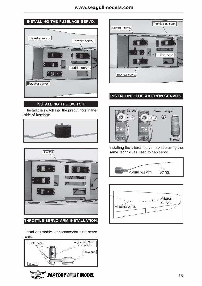
THROTTLE SERVO ARM INSTALLATION.
Install the switch into the precut hole in theside of fuselage.
INSTALLING THE FUSELAGE SERVO.
Throttle servo .Elevator servo .
Elevator servo .
Rudder servo .
INSTALLING THE AILERON SERVOS.
Servos. Small weight.
Thread.
Installing the aileron servo in place using thesame techniques used to flap servo.
String.Small weight.
Electric wire.
AileronServo.
INSTALLING THE SWITCH.
Install adjustable servo connector in the servoarm.
Adjustable Servoconnector.
Servo arm.
Throttle servo arm.Elevator servo.
Rudder servo
Elevator servo.
Switch.
Loctite secure.
1PCS.
PERCIVAL MEW GULL Instruction Manual
16
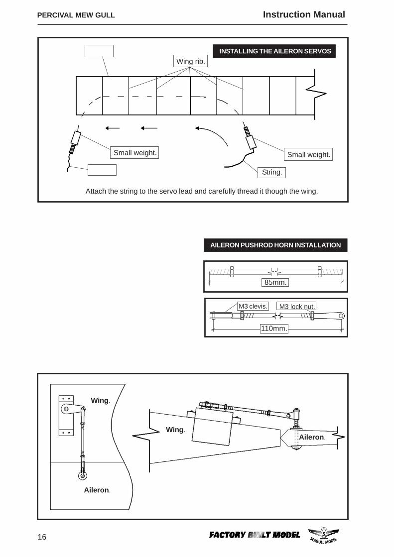
Aileron.
Wing.
Wing.Aileron.
Attach the string to the servo lead and carefully thread it though the wing.
INSTALLING THE AILERON SERVOSWing rib.
Small weight. Small weight.
String.
AILERON PUSHROD HORN INSTALLATION
M3 lock nut.M3 clevis.
85mm.
110mm.
www.seagullmodels.com
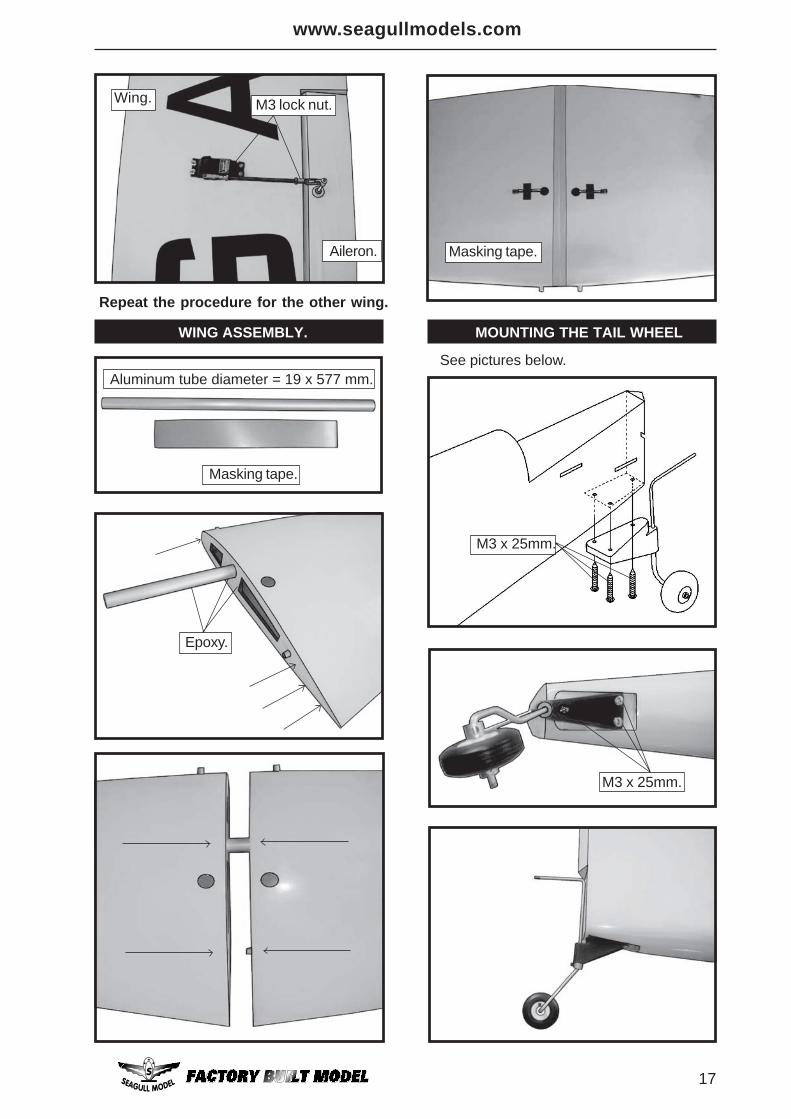
17
WING ASSEMBLY.
M3 lock nut.
Aileron.
Repeat the procedure for the other wing.
Aluminum tube diameter = 19 x 577 mm.
Masking tape.
Masking tape.
M3 x 25mm.
M3 x 25mm.
MOUNTING THE TAIL WHEEL
See pictures below.
Wing.
Epoxy.
PERCIVAL MEW GULL Instruction Manual
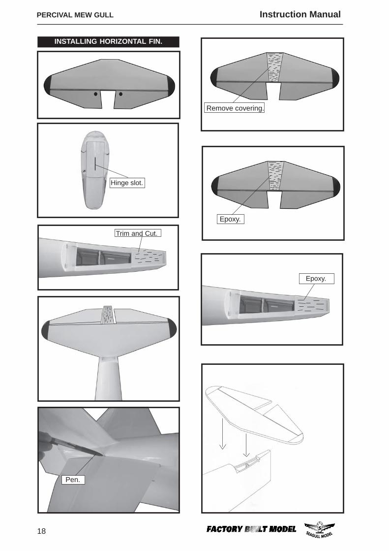
18
INSTALLING HORIZONTAL FIN.
Pen.
Remove covering.
Hinge slot.
Trim and Cut.
Epoxy.
Epoxy.
www.seagullmodels.com
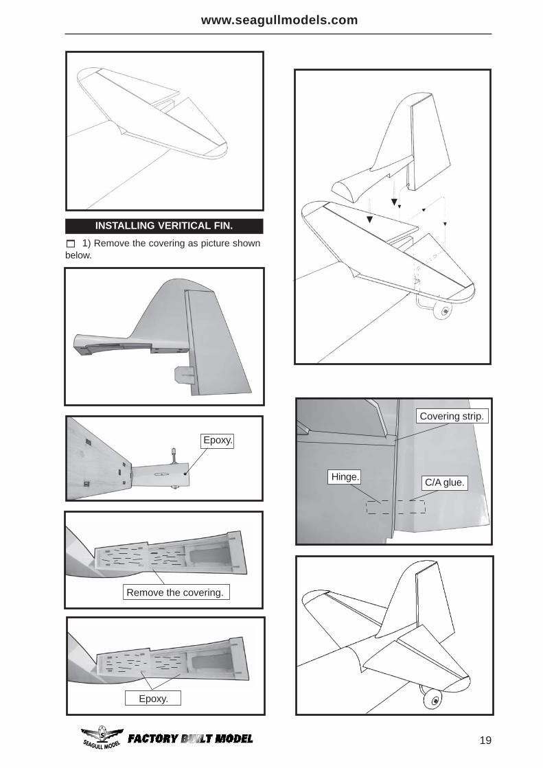
19
INSTALLING VERITICAL FIN.
1) Remove the covering as picture shownbelow.
Remove the covering.
Epoxy.
Epoxy.
Hinge. C/A glue.
Covering strip.
PERCIVAL MEW GULL Instruction Manual
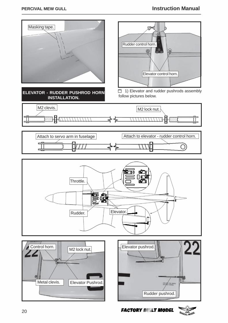
20
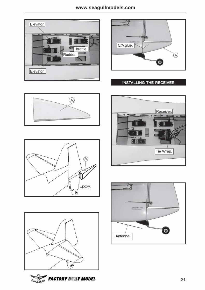
ELEVATOR - RUDDER PUSHROD HORNINSTALLATION.
1) Elevator and rudder pushrods assembly follow pictures below.
Rudder control horn.
Elevator control horn.
M2 clevis. M2 lock nut.
Attach to servo arm in fuselage Attach to elevator - rudder control horn.
Elevator.
Throttle.
Rudder.
Elevator Pushrod.
M2 lock nut.Control horn.
Metal clevis.
Elevator pushrod.
Rudder pushrod.
Masking tape.
www.seagullmodels.com
21
INSTALLING THE RECEIVER.
Elevator.
Elevator.
Throttle.Rudder.
A.
A.
Epoxy.
A.
C/A glue.
Tie Wrap.
Receiver.
Antenna.
PERCIVAL MEW GULL Instruction Manual
22
D) Check the rudder. Looking from be-hind the airplane, move the rudder stick to theright. The rudder should move to the right. If itdoes not, flip the servo reversing switch onyour transmitter to change the direction.
FLIGHT PREPARATION.
A) Check the operation and direction ofthe elevator, rudder, ailerons and throttle.
C) Check the elevator first. Pull back onthe elevator stick. The elevator halves shouldmove up. If it they do not, flip the servo re-versing switch on your transmitter to changethe direction.
B) Plug in your radio system per themanufacturer's instructions and turn every-thing on.
4) By moving the position of the adjust-able control horn out from the control surface,you will decrease the amount of throw of thatcontrol surface. Moving the adjustable con-trol horn toward the control surface will in-crease the amount of throw.
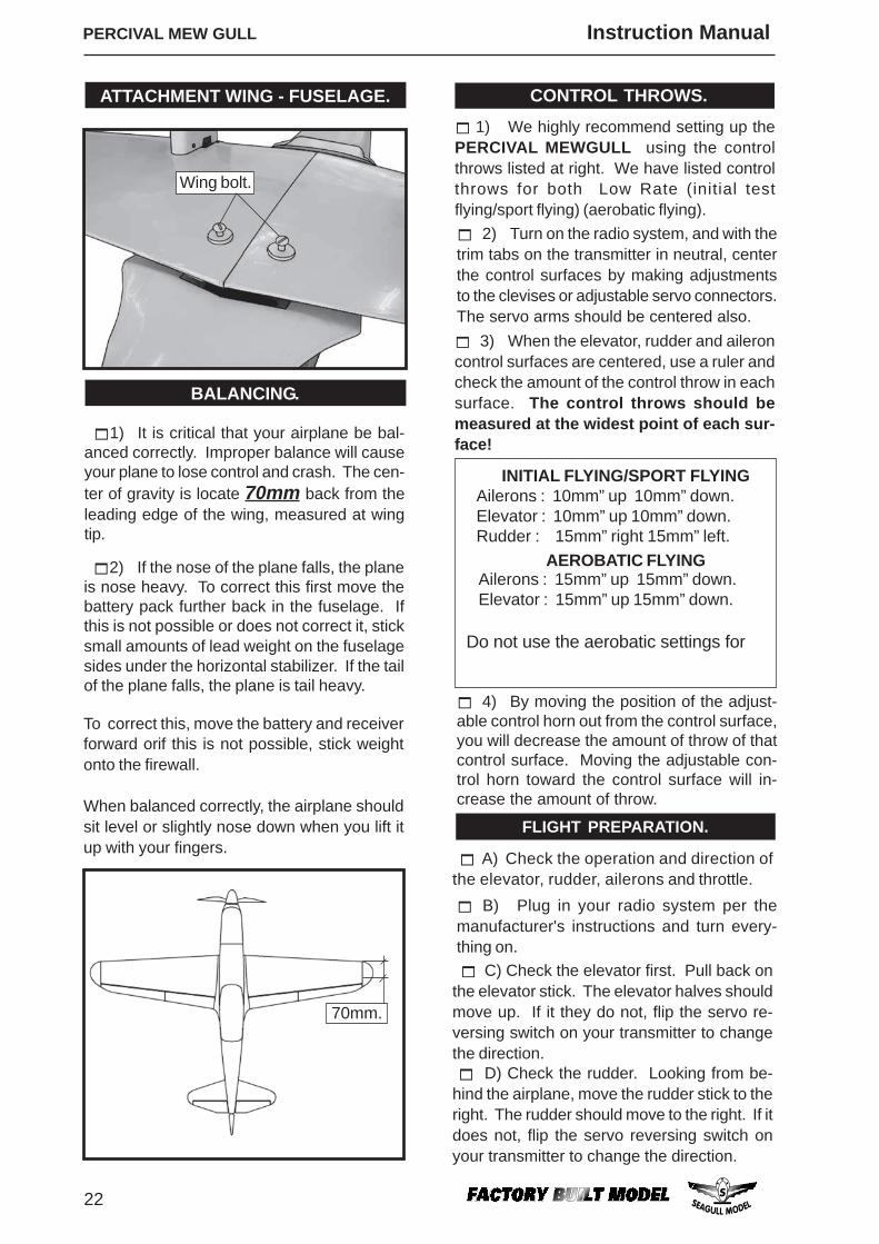
1) We highly recommend setting up thePERCIVAL MEWGULL using the controlthrows listed at right. We have listed controlthrows for both Low Rate (initial testflying/sport flying) (aerobatic flying).
3) When the elevator, rudder and aileroncontrol surfaces are centered, use a ruler andcheck the amount of the control throw in eachsurface. The control throws should bemeasured at the widest point of each sur-face!
2) Turn on the radio system, and with thetrim tabs on the transmitter in neutral, centerthe control surfaces by making adjustmentsto the clevises or adjustable servo connectors.The servo arms should be centered also.
CONTROL THROWS.
2) If the nose of the plane falls, the planeis nose heavy. To correct this first move thebattery pack further back in the fuselage. Ifthis is not possible or does not correct it, sticksmall amounts of lead weight on the fuselagesides under the horizontal stabilizer. If the tailof the plane falls, the plane is tail heavy.
To correct this, move the battery and receiverforward orif this is not possible, stick weightonto the firewall.
When balanced correctly, the airplane shouldsit level or slightly nose down when you lift itup with your fingers.
1) It is critical that your airplane be bal-anced correctly. Improper balance will causeyour plane to lose control and crash. The cen-ter of gravity is locate 70mm back from theleading edge of the wing, measured at wingtip.
BALANCING.
70mm.
Wing bolt.
Do not use the aerobatic settings for
INITIAL FLYING/SPORT FLYINGAilerons : 10mm” up 10mm” down.Elevator : 10mm” up 10mm” down.Rudder : 15mm” right 15mm” left.
AEROBATIC FLYINGAilerons : 15mm” up 15mm” down.Elevator : 15mm” up 15mm” down.
ATTACHMENT WING - FUSELAGE.
www.seagullmodels.com
23
2) Check every bolt and every glue jointin the PERCIVAL MEWGULL to ensure thateverything is tight and well bonded.
E)Check the throttle. Moving the throttlestick forward should open the carburetor bar-rel. If it does not, flip the servo reversing switchon your transmitter to change the direction. F) From behind the airplane, look at theaileron on the right wing half. Move the aileronstick to the right. The right aileron should moveup and the other aileron should move down. Ifit does not, flip the servo reversing switch onyour transmitter to change the direction.
PREFLIGHT CHECK.
1) Completely charge your transmitterand receiver batteries before your first day offlying.
6) Check to ensure the control surfacesare moving the proper amount for both lowand high rate settings.
8) Properly balance the propeller. An outof balance propeller will cause excessive vi-bration which could lead to engine and/or air-frame failure.
7) Check the receiver antenna. It shouldbe fully extended and not coiled up inside thefuselage.
5) If your radio transmitter is equippedwith dual rate switches double check that theyare on the low rate setting for your first fewflights.
3) Double check the balance of the air-plane. Do this with the fuel tank empty. 4) Check the control surfaces. All shouldmove in the correct direction and not bind inany way.
FOR USA MARKET ONLYLY.
As the user of this product, you are solely responsible for operating it in a manner that does not endanger yourselfand others or result in damage to the product or the property of others.Carefully follow the directions and warnings for this and any optional support equipment (chargers, rechargeablebattery packs, etc.) that you use.This model is controlled by a radio signal that is subject to interference from many sources outside your control.This interference can cause momentary loss of control so it is necessary to always keep a safe distance in alldirections around your model, as this margin will help to avoidcollisions or injury.• Always operate your model in an open area away from cars, traffic or people.• Avoid operating your model in the street where injury or damage can occur.• Never operate the model out into the street or populated areas for any reason.• Never operate your model with low transmitter batteries.• Carefully follow the directions and warnings for this and any optional support equipment (chargers, rechargeablebattery packs, etc.) that you use.• Keep all chemicals, small parts and anything electrical out of the reach of children.• Moisture causes damage to electronics. Avoid water exposure to all equipment not specifically designed andprotected for this purpose.
Safety,Precautions and Warnings
Warranty Period:Exclusive Warranty- Horizon Hobby, Inc., (Horizon) warranties that the Products purchased (the “Product”)will be free from defects in materials and workmanship at the date of purchase by the Purchaser.Limited Warranty(a) This warranty is limited to the original Purchaser (“Purchaser”) and is not transferable. REPAIR OR REPLACEMENTAS PROVIDED UNDER THIS WARRANTY IS THE EXCLUSIVE REMEDY OF THE PURCHASER. This warrantycovers only those Products purchased from an authorized Horizon dealer. Third party transactions are not coveredby this warranty. Proof of purchase is required for warranty claims. Further, Horizon reserves the right to change ormodify this warranty without notice and disclaims all other warranties, express or implied.
(b) Limitations- HORIZON MAKES NO WARRANTY OR REPRESENTATION, EXPRESS OR IMPLIED, ABOUT NON-INFRINGEMENT, MERCHANTABILITY OR FITNESS FOR A PARTICULAR PURPOSE OF THE PRODUCT. THEPURCHASER ACKNOWLEDGES THAT THEY ALONE HAVE DETERMINED THAT THE PRODUCT WILL SUITABLYMEET THEREQUIREMENTS OF THE PURCHASER’S INTENDED USE. (c) Purchaser Remedy- Horizon’s sole obligation hereunder shall be that Horizon will, at its option, (i) repair or (ii)replace, any Product determined by Horizon to be defective. In the event of a defect, these are the Purchaser’sexclusive remedies. Horizon reserves the right to inspect any and all equipment involved in a warranty claim. Repairor replacement decisions are at the sole discretion of Horizon. This warranty does not cover cosmetic damage ordamage due to acts of God, accident, misuse, abuse, negligence, commercial use, or modification of or to any part
We wish you many safe and enjoyableflights with your PERCIVAL MEWGULL.
PERCIVAL MEW GULL Instruction Manual
24
of the Product. This warranty does not cover damage due to improper installation, operation, maintenance, orattempted repair by anyone other than Horizon. Return of any goods by Purchaser must be approved in writing byHorizon before shipment.
Damage Limits:HORIZON SHALL NOT BE LIABLE FOR SPECIAL, INDIRECT OR CONSEQUENTIAL DAMAGES, LOSS OF PROFITSOR PRODUCTION OR COMMERCIAL LOSS IN ANY WAY CONNECTED WITH THE PRODUCT, WHETHER SUCHCLAIM IS BASED IN CONTRACT, WARRANTY, NEGLIGENCE, OR STRICT LIABILITY. Further, in no event shall theliability of Horizon exceed the individual price of the Product on which liability is asserted. As Horizon has no controlover use, setup, final assembly, modification or misuse, no liability shall be assumed nor accepted for any resultingdamage or injury. By the act of use, setup or assembly, the user accepts all resulting liability.
If you as the Purchaser or user are not prepared to accept the liability associated with the use of this Product, you areadvised to return this Product immediately in new and unused condition to the place of purchase.Law: These Terms are governed by Illinois law (without regard to conflict of law principals).Safety Precautions:This is a sophisticated hobby Product and not a toy. It must be operated with caution and common sense andrequires some basic mechanical ability. Failure to operate this Product in a safe and responsible manner couldresult in injury or damage to the Product or other property. This Product is not intended for use by children withoutdirect adult supervision. The Product manual contains instructions for safety, operation and maintenance. It isessential to read and follow all the instructions and warnings in the manual, prior to assembly, setup or use, inorder to operate correctly and avoid damage or injury.Questions, Assistance, and Repairs:Your local hobby store and/or place of purchase cannot provide warranty support or repair. Once assembly, setup oruse of the Product has been started, you must contact Horizon directly. This will enable Horizon to better answeryour questions and service you in the event that you may need any assistance. For questions or assistance, pleasedirect your email to [email protected], or call 877.504.0233 toll free to speak to a service technician.Inspection or RepairsIf this Product needs to be inspected or repaired, please call for a Return Merchandise Authorization (RMA). Pack theProduct securely using a shipping carton. Please note that original boxes may be included, but are not designed towithstand the rigors of shipping without additional protection. Ship via a carrier that provides tracking and insurancefor lost or damaged parcels, as Horizon is not responsible for merchandise until it arrives and is accepted at ourfacility. A Service Repair Request is available at www.horizonhobby.com on the “Support” tab. If you do not haveinternet access, please include a letter with your complete name, street address, email address and phonenumber where you can be reached during business days, your RMA number, a list of the included items, method ofpayment for any non-warranty expenses and a brief summary of the problem. Your original sales receipt must alsobe included for warranty consideration. Be sure your name, address, and RMA number are clearly written on theoutside of the shipping carton.
Warranty Inspection and RepairsTo receive warranty service, you must include your original sales receipt verifying the proof-of-purchase date.Provided warranty conditions have been met, your Product will be repaired or replaced free of charge. Repair orreplacement decisions are at the sole discretion of Horizon Hobby.
Non-Warranty RepairsShould your repair not be covered by warranty the repair will be completed and payment will be requiredwithout notification or estimate of the expense unless the expense exceeds 50% of the retail purchase cost. Bysubmitting the item for repair you are agreeing to payment of the repair without notification. Repair estimates areavailable upon request. You must include this request with your repair. Non-warranty repair estimates will be billeda minimum of ½ hour of labor. In addition you will be billed for return freight. Please advise us of your preferredmethod of payment. Horizon accepts money orders and cashiers checks, as well as Visa, MasterCard, AmericanExpress, and Discover cards. If you choose to pay by credit card, please include your credit card number andexpiration date. Any repair left unpaid or unclaimed after 90 days will be considered abandoned and will be disposedof accordingly. Please note: non-warranty repair is only available on electronics and model engines.
Electronics and engines requiring inspection or repair should be shipped to the following address:
Horizon Service Center4105 Fieldstone Road
Champaign, Illinois 61822
All other Products requiring warranty inspection or repair should be shipped to the following address:
Horizon Product Support4105 Fieldstone Road
Champaign, Illinois 61822
Please call 877-504-0233 with any questions or concerns regarding this product or warranty.