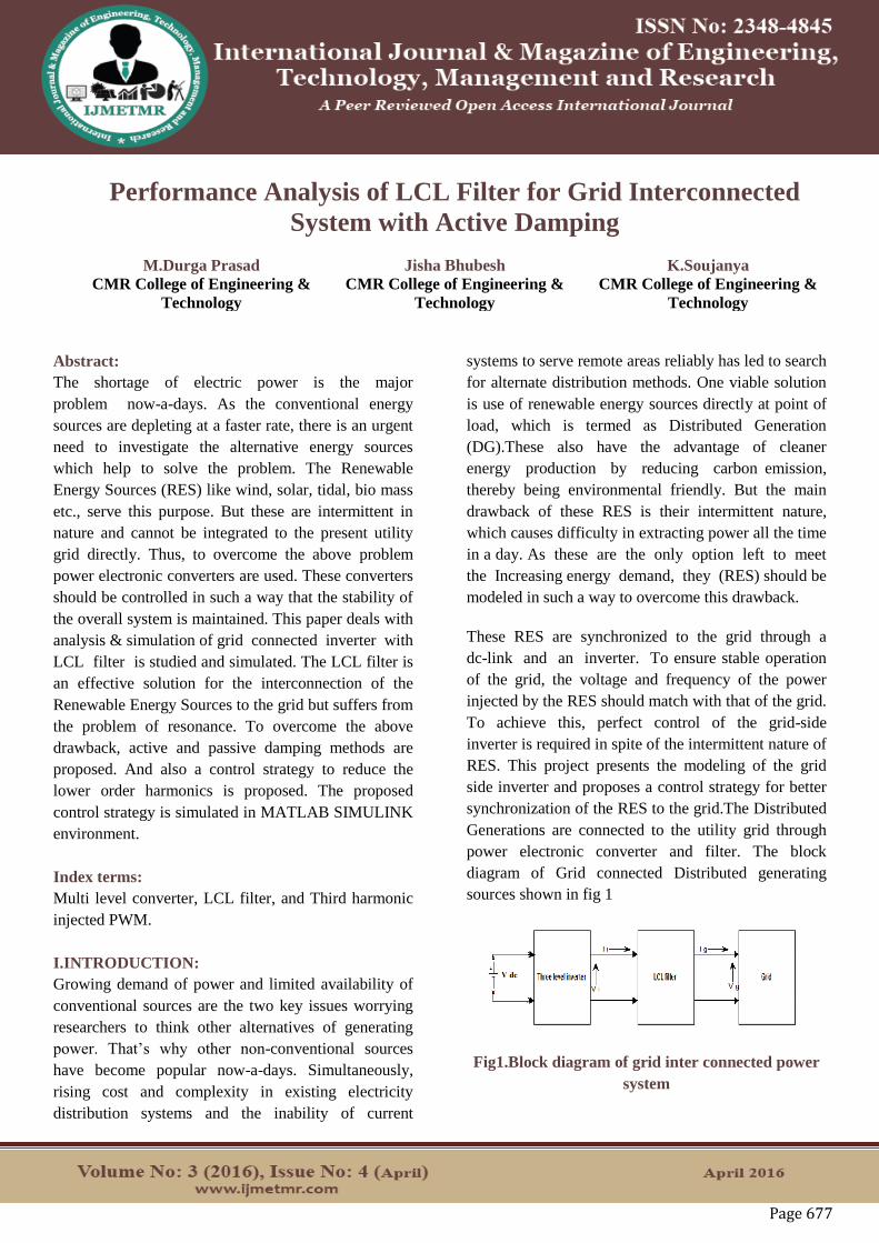
Page 677 Performance Analysis of LCL Filter for Grid Interconnected System with Active Damping M.Durga Prasad CMR College of Engineering & Technology Jisha Bhubesh CMR College of Engineering & Technology K.Soujanya CMR College of Engineering & Technology Abstract: The shortage of electric power is the major problem now-a-days. As the conventional energy sources are depleting at a faster rate, there is an urgent need to investigate the alternative energy sources which help to solve the problem. The Renewable Energy Sources (RES) like wind, solar, tidal, bio mass etc., serve this purpose. But these are intermittent in nature and cannot be integrated to the present utility grid directly. Thus, to overcome the above problem power electronic converters are used. These converters should be controlled in such a way that the stability of the overall system is maintained. This paper deals with analysis & simulation of grid connected inverter with LCL filter is studied and simulated. The LCL filter is an effective solution for the interconnection of the Renewable Energy Sources to the grid but suffers from the problem of resonance. To overcome the above drawback, active and passive damping methods are proposed. And also a control strategy to reduce the lower order harmonics is proposed. The proposed control strategy is simulated in MATLAB SIMULINK environment. Index terms: Multi level converter, LCL filter, and Third harmonic injected PWM. I.INTRODUCTION: Growing demand of power and limited availability of conventional sources are the two key issues worrying researchers to think other alternatives of generating power. That’s why other non-conventional sources have become popular now-a-days. Simultaneously, rising cost and complexity in existing electricity distribution systems and the inability of current systems to serve remote areas reliably has led to search for alternate distribution methods. One viable solution is use of renewable energy sources directly at point of load, which is termed as Distributed Generation (DG).These also have the advantage of cleaner energy production by reducing carbon emission, thereby being environmental friendly. But the main drawback of these RES is their intermittent nature, which causes difficulty in extracting power all the time in a day. As these are the only option left to meet the Increasing energy demand, they (RES) should be modeled in such a way to overcome this drawback. These RES are synchronized to the grid through a dc-link and an inverter. To ensure stable operation of the grid, the voltage and frequency of the power injected by the RES should match with that of the grid. To achieve this, perfect control of the grid-side inverter is required in spite of the intermittent nature of RES. This project presents the modeling of the grid side inverter and proposes a control strategy for better synchronization of the RES to the grid.The Distributed Generations are connected to the utility grid through power electronic converter and filter. The block diagram of Grid connected Distributed generating sources shown in fig 1 Fig1.Block diagram of grid inter connected power system
Transcript
Page 677
Performance Analysis of LCL Filter for Grid Interconnected
System with Active Damping
M.Durga Prasad
CMR College of Engineering &
Technology
Jisha Bhubesh
CMR College of Engineering &
Technology
K.Soujanya
CMR College of Engineering &
Technology
Abstract:
The shortage of electric power is the major
problem now-a-days. As the conventional energy
sources are depleting at a faster rate, there is an urgent
need to investigate the alternative energy sources
which help to solve the problem. The Renewable
Energy Sources (RES) like wind, solar, tidal, bio mass
etc., serve this purpose. But these are intermittent in
nature and cannot be integrated to the present utility
grid directly. Thus, to overcome the above problem
power electronic converters are used. These converters
should be controlled in such a way that the stability of
the overall system is maintained. This paper deals with
analysis & simulation of grid connected inverter with
LCL filter is studied and simulated. The LCL filter is
an effective solution for the interconnection of the
Renewable Energy Sources to the grid but suffers from
the problem of resonance. To overcome the above
drawback, active and passive damping methods are
proposed. And also a control strategy to reduce the
lower order harmonics is proposed. The proposed
control strategy is simulated in MATLAB SIMULINK
environment.
Index terms:
Multi level converter, LCL filter, and Third harmonic
injected PWM.
I.INTRODUCTION:
Growing demand of power and limited availability of
conventional sources are the two key issues worrying
researchers to think other alternatives of generating
power. That’s why other non-conventional sources
have become popular now-a-days. Simultaneously,
rising cost and complexity in existing electricity
distribution systems and the inability of current
systems to serve remote areas reliably has led to search
for alternate distribution methods. One viable solution
is use of renewable energy sources directly at point of
load, which is termed as Distributed Generation
(DG).These also have the advantage of cleaner
energy production by reducing carbon emission,
thereby being environmental friendly. But the main
drawback of these RES is their intermittent nature,
which causes difficulty in extracting power all the time
in a day. As these are the only option left to meet
the Increasing energy demand, they (RES) should be
modeled in such a way to overcome this drawback.
These RES are synchronized to the grid through a
dc-link and an inverter. To ensure stable operation
of the grid, the voltage and frequency of the power
injected by the RES should match with that of the grid.
To achieve this, perfect control of the grid-side
inverter is required in spite of the intermittent nature of
RES. This project presents the modeling of the grid
side inverter and proposes a control strategy for better
synchronization of the RES to the grid.The Distributed
Generations are connected to the utility grid through
power electronic converter and filter. The block
diagram of Grid connected Distributed generating
sources shown in fig 1
Fig1.Block diagram of grid inter connected power
system
Page 678
The Distributed Generation may represent wind, tidal,
solar, etc. Which are Non conventional energy sources,
these plants generates either AC or DC. The Generated
power can be stored in batteries in the form of DC
source. The main aim of converter and filter is to
extract maximum power from Generated dc sources.
The Converter converts the dc power to ac and feed it
to the utility grid. The main aim of this converter is to
keep the frequency and phase of output current same
as grid voltage. The control algorithm of this converter
has the following tasks- To control the active power
injected into the grid. To control the reactive power
transfer between the DC source and the grid. To
maintain Grid Synchronization. In addition to the
above main tasks, the converter also regulates local
voltage and frequency, compensates the voltage
harmonics and may does active filtering when
required. Thus, to control the power injected into
the grid, the control of converter is of utmost
important. But the output current from the inverter
contains harmonics. So to filter out these harmonics a
filter is used at the output of the inverter.
A. WHY LCL-FILTER?
There are different types of filter configurations in the
literature like- L, LC, LCL. The characteristics and the
application of each type of filter are as follows-
B. L-Filter:
The L-filter is a first order filter having -
20dB/decade attenuation over the whole frequency
range. So this type of filter has its application
with converters having high switching frequency
where the attenuation is sufficient. The L-filter
topology is as shown in Fig. 2.2 and the transfer
function of the L-filter is- F(S) = 1
LS
(1)
C. LC Filter:
The LC Filter is a second order filter giving -
40db/decade attenuation. And it has better damping
characters than L filter. This LC- filter is suited to
configurations where the load impedance across
capacitor is relatively high at and above the switching
frequency. The cost and reactive power consumption
of the LC filter are more than to the L filter because of
the addition of the shunt element. But this filter suffers
from the problem of infinite gain at resonant
frequency. The transfer function of the LC-filter is-
F(s) = SC
LCS2−1 (2)
D. LCL-Filter:
This is a third order filter with an attenuation of -
60dB/decade above resonant frequency. So it can be
used for converters with low switching frequency. It
can achieve reduced levels of harmonic distortion with
small value of inductance. Thus, this filter suits better
for the interconnection of RES with utility grid. On the
other hand LCL filter may cause both dynamic and
steady state input current distortion due to resonance.
II. MODELING OF GRID-CONNECTED MULTI
LEVEL INVERTER
A new topology has mentioned, three level T- type
neutral point clamped (3L-TNPC). The benefit of 3L-
TNPC is the three level output voltage waveform
while there are no restrictions to the switching scheme
as in three level NPC. A three level TNPC phase leg
consists of only 8 semiconductors: 4 IGBTs and 4 anti
parallel freewheeling diodes. In this 3L TNPC
topology semiconductors with different breakdown
voltages are used. T1 and T4 need to withstand the full
dc link voltage.
The inner switches connect AC to neutral and must be
able to block half of the DC link voltage. In 3L TNPC
topology the conduction paths are either through one
higher blocking semiconductors or two lower blocking
devices in series. Numbering semiconductors are
shown in figure 2. Inherits the advantage that the exact
same switching pattern can be used for both 3L NPC
and 3L TNPC topology. The mathematical model of
the grid-connected Distributed Generation is necessary
in order to simulate and study the performance of the
system at different operating conditions.
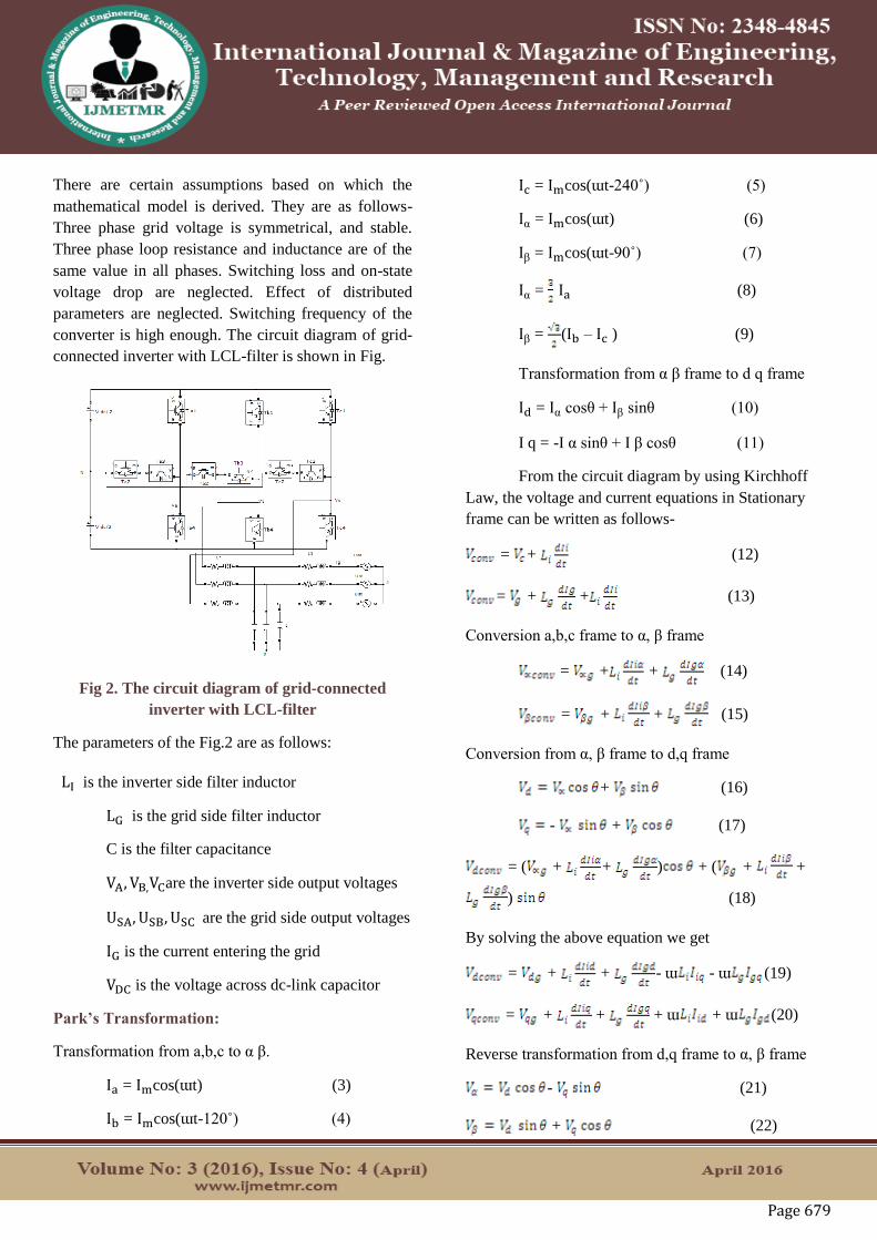
Page 679
There are certain assumptions based on which the
mathematical model is derived. They are as follows-
Three phase grid voltage is symmetrical, and stable.
Three phase loop resistance and inductance are of the
same value in all phases. Switching loss and on-state
voltage drop are neglected. Effect of distributed
parameters are neglected. Switching frequency of the
converter is high enough. The circuit diagram of grid-
connected inverter with LCL-filter is shown in Fig.
Fig 2. The circuit diagram of grid-connected
inverter with LCL-filter
The parameters of the Fig.2 are as follows:
LI is the inverter side filter inductor
LG is the grid side filter inductor
C is the filter capacitance
VA, VB,VCare the inverter side output voltages
USA, USB, USC are the grid side output voltages
IG is the current entering the grid
VDC is the voltage across dc-link capacitor
Park’s Transformation:
Transformation from a,b,c to α β.
Ia = Imcos(ɯt) (3)
Ib = Imcos(ɯt-120˚) (4)
Ic = Imcos(ɯt-240˚) (5)
Iα = Imcos(ɯt) (6)
Iβ = Imcos(ɯt-90˚) (7)
Iα = Ia (8)
Iβ = (Ib – Ic ) (9)
Transformation from α β frame to d q frame
Id = Iα cosθ + Iβ sinθ (10)
I q = -I α sinθ + I β cosθ (11)
From the circuit diagram by using Kirchhoff
Law, the voltage and current equations in Stationary
frame can be written as follows-
= + (12)
= + + (13)
Conversion a,b,c frame to α, β frame
= + + (14)
= + + (15)
Conversion from α, β frame to d,q frame
+ (16)
- + (17)
= ( + + ) + ( + +
) (18)
By solving the above equation we get
= + + - ɯ - ɯ (19)
= + + + ɯ + ɯ (20)
Reverse transformation from d,q frame to α, β frame
- (21)
+ (22)
Page 680
Transformation from α, β frame to a,b,c frame
= (23)
= - (24)
= -( ) (25)
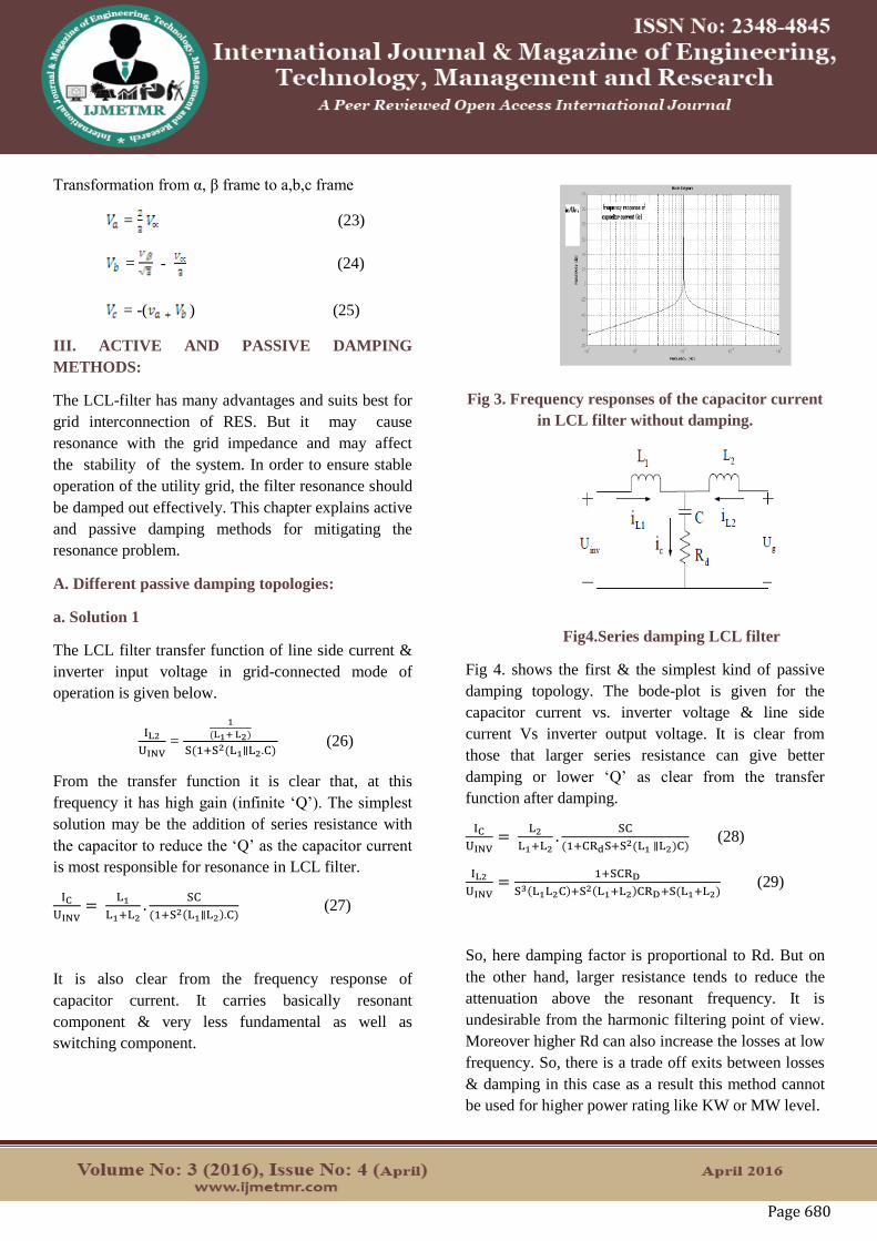
III. ACTIVE AND PASSIVE DAMPING
METHODS:
The LCL-filter has many advantages and suits best for
grid interconnection of RES. But it may cause
resonance with the grid impedance and may affect
the stability of the system. In order to ensure stable
operation of the utility grid, the filter resonance should
be damped out effectively. This chapter explains active
and passive damping methods for mitigating the
resonance problem.
A. Different passive damping topologies:
a. Solution 1
The LCL filter transfer function of line side current &
inverter input voltage in grid-connected mode of
operation is given below.
IL2
UINV =
1
(L1+ L2)
S(1+S2(L1∥L2.C) (26)
From the transfer function it is clear that, at this
frequency it has high gain (infinite ‘Q’). The simplest
solution may be the addition of series resistance with
the capacitor to reduce the ‘Q’ as the capacitor current
is most responsible for resonance in LCL filter.
IC
UINV=
L1
L1+L2.
SC
(1+S2(L1∥L2).C) (27)
It is also clear from the frequency response of
capacitor current. It carries basically resonant
component & very less fundamental as well as
switching component.
Fig 3. Frequency responses of the capacitor current
in LCL filter without damping.
Fig4.Series damping LCL filter
Fig 4. shows the first & the simplest kind of passive
damping topology. The bode-plot is given for the
capacitor current vs. inverter voltage & line side
current Vs inverter output voltage. It is clear from
those that larger series resistance can give better
damping or lower ‘Q’ as clear from the transfer
function after damping.
IC
UINV=
L2
L1+L2.
SC
(1+CRdS+S2(L1 ∥L2)C) (28)
IL2
UINV=
1+SCRD
S3(L1L2C)+S2(L1+L2)CRD+S(L1+L2) (29)
So, here damping factor is proportional to Rd. But on
the other hand, larger resistance tends to reduce the
attenuation above the resonant frequency. It is
undesirable from the harmonic filtering point of view.
Moreover higher Rd can also increase the losses at low
frequency. So, there is a trade off exits between losses
& damping in this case as a result this method cannot
be used for higher power rating like KW or MW level.
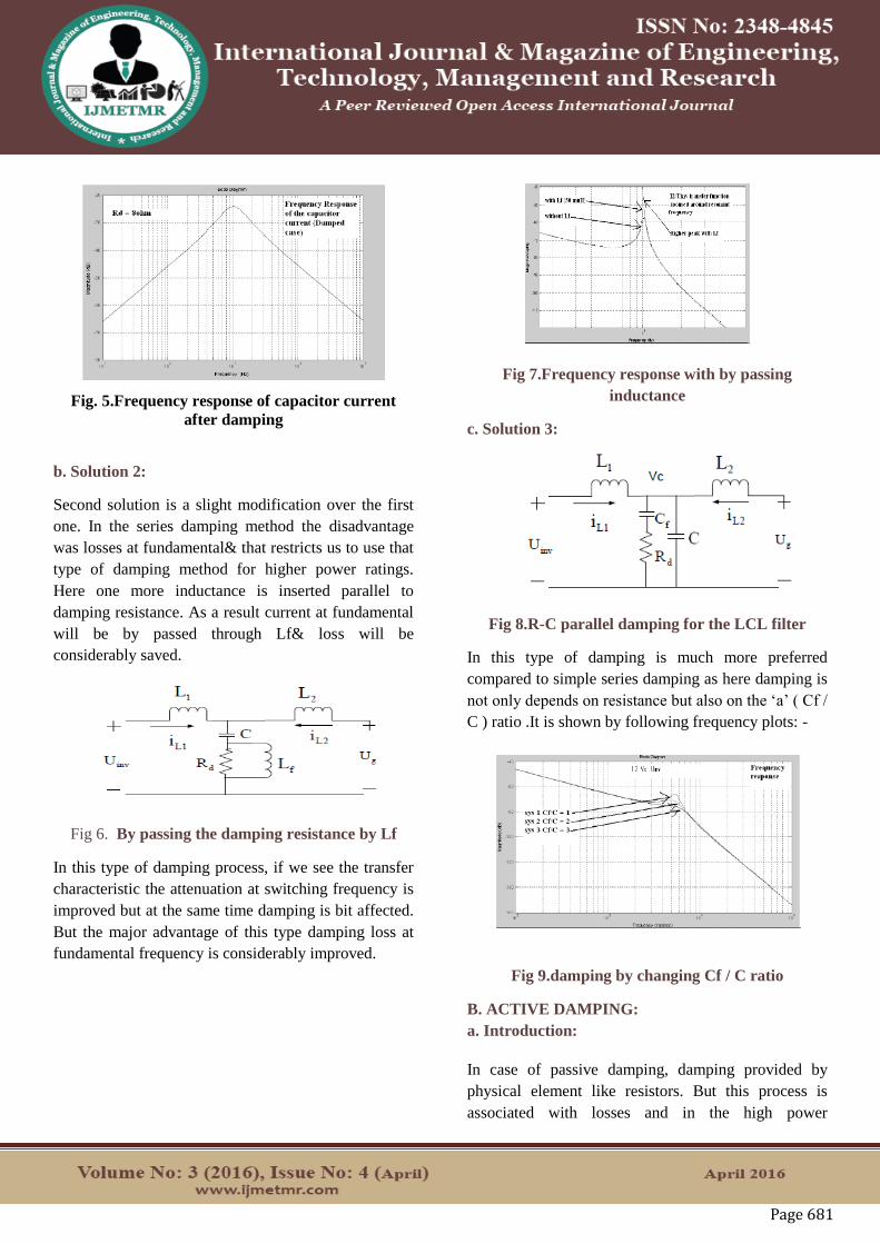
Page 681
Fig. 5.Frequency response of capacitor current
after damping
b. Solution 2:
Second solution is a slight modification over the first
one. In the series damping method the disadvantage
was losses at fundamental& that restricts us to use that
type of damping method for higher power ratings.
Here one more inductance is inserted parallel to
damping resistance. As a result current at fundamental
will be by passed through Lf& loss will be
considerably saved.
Fig 6. By passing the damping resistance by Lf
In this type of damping process, if we see the transfer
characteristic the attenuation at switching frequency is
improved but at the same time damping is bit affected.
But the major advantage of this type damping loss at
fundamental frequency is considerably improved.
Fig 7.Frequency response with by passing
inductance
c. Solution 3:
Fig 8.R-C parallel damping for the LCL filter
In this type of damping is much more preferred
compared to simple series damping as here damping is
not only depends on resistance but also on the ‘a’ ( Cf /
C ) ratio .It is shown by following frequency plots: -
Fig 9.damping by changing Cf / C ratio
B. ACTIVE DAMPING:
a. Introduction:
In case of passive damping, damping provided by
physical element like resistors. But this process is
associated with losses and in the high power
Page 682
application with process cannot be afforded. To reduce
losses and improve the performance inductors,
capacitors are provided along with resistors.In case of
active damping, damping is being provided by means
of control algorithm, this process is not a loss process
so this process is much more attractive. But there is a
limitation of active damping, such as this control
technique depends on the switching of power
converter,so this is effective only when power
converter is switching. On the other hand switching
frequency of the power converter is limited hence the
control BW of the active damping is also limited.
There are broadly two methods of active damping can
be thought one is based on traditional PI-controller and
the other is based on generalized statespace approach.
In this chapter we will focus on a method of active
damping based on State-space (arbitrary pole
placement).
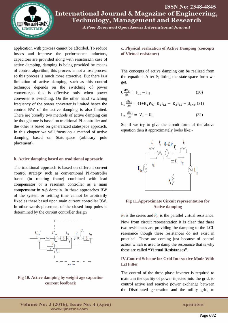
b. Active damping based on traditional approach:
The traditional approach is based on different current
control strategy such as conventional PI-controller
based (in rotating frame) combined with lead
compensator or a resonant controller as a main
compensator in α-β domain. In these approaches BW
of the system or settling time cannot be arbitrarily
fixed as these based upon main current controller BW.
In other words placement of the closed loop poles is
determined by the current controller design
Fig 10. Active damping by weight age capacitor
current feedback
c. Physical realization of Active Damping (concepts
of Virtual resistance)
The concepts of active damping can be realized from
the equation. After Splitting the state-space form we
get,
CdVc
dt= IL1 − Il2 (30)
L1dIL1
dt = -(1+K1)VC- K2IL1 − K3IL2 + UINV (31)
L2 diL2
dt= VC − UG (32)
So, if we try to give the circuit form of the above
equation then it approximately looks like:-
Fig 11.Approximate Circuit representation for
Active damping
is the series and is the parallel virtual resistance.
Now from circuit representation it is clear that these
two resistances are providing the damping to the LCL
resonance though these resistances do not exist in
practical. These are coming just because of control
action which is used to damp the resonance that is why
these are called “Virtual Resistances”.
IV.Control Scheme for Grid Interactive Mode With
Lcl Filter
The control of the three phase inverter is required to
maintain the quality of power injected into the grid, to
control active and reactive power exchange between
the Distributed generation and the utility grid, to
Page 683
maintain grid synchronization. Here in this chapter dq-
based control strategy is adopted. The control scheme
for LCL filter based system is quite different as well as
complicated from those of simple L filter based grid-
connected system.
A. Overview of control loop consisting of three
states of System
Fig 12.Conventional three loop control strategy for
LCL filter
B.Reduction of Controller complexity
But here for this type of filter the capacitor voltage can
be indirectly controlled so there is no need of capacitor
voltage controller for LCL filter. The = and
the = dt, Hence if we can control and
separately then that itself control the followed by .
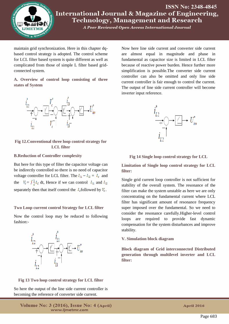
Two Loop current control Strategy for LCL filter
Now the control loop may be reduced to following
fashion:-
Fig 13 Two loop control strategy for LCL filter
So here the output of the line side current controller is
becoming the reference of converter side current.
Now here line side current and converter side current
are almost equal in magnitude and phase in
fundamental as capacitor size is limited in LCL filter
because of reactive power burden. Hence further more
simplification is possible.The converter side current
controller can also be omitted and only line side
current controller is fair enough to control the current.
The output of line side current controller will become
inverter input reference.
Fig 14 Single loop control strategy for LCL
Limitation of Single loop control strategy for LCL
filter:
Single grid current loop controller is not sufficient for
stability of the overall system. The resonance of the
filter can make the system unstable as here we are only
concentrating on the fundamental current where LCL
filter has significant amount of resonance frequency
super imposed over the fundamental. So we need to
consider the resonance carefully.Higher-level control
loops are required to provide fast dynamic
compensation for the system disturbances and improve
stability.
V. Simulation block diagram
Block diagram of Grid interconnected Distributed
generation through multilevel inverter and LCL
filter:
Page 684
Fig 15. SimulationBlock diagram of Grid
interconnected Distributed generation through
multilevel inverter and LCL filter
Block diagram of control loop:
Fig 16 Simulation Block diagram of control loop
Construction of current control loop:
Fig 17. Simulation Construction of current control
loop
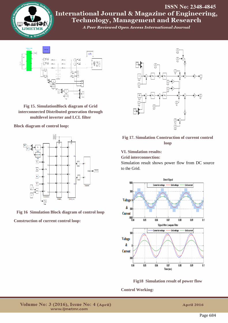
VI. Simulation results:
Grid interconnection:
Simulation result shows power flow from DC source
to the Grid.
Fig18 Simulation result of power flow
Control Working:
Page 685
Simulation results shows control working to meet
reference with feedback for various values of grid
current.
Fig19.
Simulation result of stability of control system
Simulation results shows control working to meet
reference with feedback for different input DC voltage
Transients.
Fig 20. Simulation result for transients in DC
voltages
Simulation results shows control working to meet
reference with feedback for different Grid frequency
Transients.
Fig 21. Simulation result for transients in grid
frequency
Simulation results shows control working to meet
reference with feedback for different Grid voltage
Transients.
Fig 22. Simulation result for transients in grid
voltage
Page 686
VII. CONCLUSION:
Performance of LCL filter for grid interconnection was
studied and simulated. And found that, among
different filter topologies present in the literature, the
LCL filter best suits for grid interconnection
application. And Active damping method of LCL filter
has better response. The passive damping method of
LCL filter is a low cost solution and is used where
efficiency can be sacrificed slightly. Two loop current
control strategy present in this project, it can achieved
control over active and reactive power flow in to the
grid. And ensure unity power factor operation with
grid interconnection. This control strategy simulated at
various transient conditions. Among different three
level converter topologies, T type neutral point
clamped (TNPC) obtained better performance with
reduced converter switches rating, and it does not
required any clamping devices, like diodes in diode
clamped multilevel converter, and capacitors in flying
capacitors multi level converter.
REFERENCES:
[1] M. Hanif.”Active Damping Techniques for
Suppressing the
LCL Filter Resonance in Distributed Generators”IEEE
Trans978-1-4799-3254-2- 2013.
[2] Dannehl J., Liserr, M. and Fuchs F.W., "Filter-


![Resonance Damping and Parameter Design Method for LCL-LC ... · The filter can be of different types [6]. Compared with the first order L filter, the third-order LCL filter can meet](https://static.documents.pub/doc/80x56/5e76b9e50c589625166846e9/resonance-damping-and-parameter-design-method-for-lcl-lc-the-filter-can-be-of.jpg)
![Conclusioni - GRIX.ITApp(1).pdf[8] M. Liserre, F. Blaabjerg, A. Dell’Aquila, “A stable three-phase LCL-filter based active rectifier without damping”, ISA 2003, Salt Lake City,](https://static.documents.pub/doc/80x56/60de65394e98c835477a202d/conclusioni-grixit-app1pdf-8-m-liserre-f-blaabjerg-a-dellaaquila.jpg)

