International Journal of Bifurcation and Chaos, Vol. 14, No. 10 (2004) 3633–3646 c World Scientific Publishing Company PERFORMANCE ANALYSIS OF MULTIPLE ACCESS CHAOTIC-SEQUENCE SPREAD-SPECTRUM COMMUNICATION SYSTEMS USING PARALLEL INTERFERENCE CANCELLATION RECEIVERS WAI M. TAM * , FRANCIS C. M. LAU † and CHI K. TSE ‡ Department of Electronic and Information Engineering, The Hong Kong Polytechnic University, Hong Kong, P. R. China * [email protected]† [email protected]‡ [email protected]Received August 1, 2003; Revised September 22, 2003 In this Letter, we apply combined linear detector/parallel interference cancellation (PIC) detectors to jointly decode symbols in a multiple access chaotic-sequence spread-spectrum com- munication system. In particular, three different types of linear detectors, namely single-user detector, decorrelating detector and minimum mean-square-error detector, are used to estimate the transmitted symbols at the first stage of the PIC detector. The technique for deriving the approximate bit error rate (BER) is described and computer simulations are performed to verify the analytical BERs. Keywords : Chaos-based communications; multiple access; multiuser detection; spread-spectrum communications; parallel interference cancellation. 1. Introduction Spread-spectrum digital modulation schemes based on chaotic sequence was first proposed by Heidari- Bateni and McGillem [1994], and Parlitz and Ergezinger [1994]. By assigning different chaotic sequences to different users, multiple access in chaotic-sequence spread-spectrum systems can be accomplished [Yang & Chua, 1997, 1998]. Since each transmitted symbol is spread by a chaotic sequence of finite length, there exist finite nonzero cross- correlations between the spread symbols from dif- ferent users. This introduces interference among the users and limits the performance of the system when the users’ symbols are decoded independently. Multiuser detection is an effective technique to reduce mutual interference between users in a multi- ple access environment. Multiuser detectors can be broadly categorized into linear and nonlinear types. For the linear detectors, a linear transformation is performed at the receiver to mitigate the mul- tiuser interference [Lupas & Verd´ u, 1989; Lupas & Verd´ u, 1990; Verd´ u, 1986; Xie et al., 1990] whereas nonlinear detectors cancel the interference in sev- eral stages by subtracting the reconstructed sig- nals from the received signals [Hui & Letaief, 1998; Xue et al., 2000; Yoon & Ness, 2002; Yoon et al., 1993]. Recently, two nonlinear multiuser detectors, namely parallel interference cancellation (PIC) and the successive interference cancellation (SIC) de- tectors, have been applied to a chaotic-sequence spread-spectrum communication system [Arg¨ uello et al., 2002]. The performance, however, has only been evaluated by computer simulations and no analytical BER has been derived. Also, the com- bined effects of the linear and nonlinear multiuser detectors have not been examined. 3633
Received August 1, 2003; Revised September 22, 2003
In this Letter, we apply combined linear detector/parallel interference cancellation (PIC)detectors to jointly decode symbols in a multiple access chaotic-sequence spread-spectrum com-munication system. In particular, three different types of linear detectors, namely single-userdetector, decorrelating detector and minimum mean-square-error detector, are used to estimatethe transmitted symbols at the first stage of the PIC detector. The technique for deriving theapproximate bit error rate (BER) is described and computer simulations are performed to verifythe analytical BERs.
Spread-spectrum digital modulation schemes basedon chaotic sequence was first proposed by Heidari-Bateni and McGillem [1994], and Parlitz andErgezinger [1994]. By assigning different chaoticsequences to different users, multiple access inchaotic-sequence spread-spectrum systems can beaccomplished [Yang & Chua, 1997, 1998]. Since eachtransmitted symbol is spread by a chaotic sequenceof finite length, there exist finite nonzero cross-correlations between the spread symbols from dif-ferent users. This introduces interference among theusers and limits the performance of the system whenthe users’ symbols are decoded independently.
Multiuser detection is an effective technique toreduce mutual interference between users in a multi-ple access environment. Multiuser detectors can bebroadly categorized into linear and nonlinear types.
For the linear detectors, a linear transformationis performed at the receiver to mitigate the mul-tiuser interference [Lupas & Verdu, 1989; Lupas &Verdu, 1990; Verdu, 1986; Xie et al., 1990] whereasnonlinear detectors cancel the interference in sev-eral stages by subtracting the reconstructed sig-nals from the received signals [Hui & Letaief, 1998;Xue et al., 2000; Yoon & Ness, 2002; Yoon et al.,1993]. Recently, two nonlinear multiuser detectors,namely parallel interference cancellation (PIC) andthe successive interference cancellation (SIC) de-tectors, have been applied to a chaotic-sequencespread-spectrum communication system [Arguelloet al., 2002]. The performance, however, has onlybeen evaluated by computer simulations and noanalytical BER has been derived. Also, the com-bined effects of the linear and nonlinear multiuserdetectors have not been examined.
3633
October 27, 2004 13:29 01154
3634 W. M. Tam et al.
Fig. 1. An N -user multiple access chaotic-sequence spread-spectrum (MA-CSSS) communication system employing single-user detectors.
In this Letter, we study three types of lin-ear detectors applied in conjunction with paral-lel interference cancellation (PIC) detector in amultiple access chaotic-sequence spread-spectrum(MA-CSSS) communication system [Tam et al.,2003]. The linear detectors include conventionalsingle-user detector, multiuser decorrelating detec-tor (DD) and multiuser minimum mean-square-error (MMSE) detector [Madsen & Cho, 1999; Tamet al., 2002, 2004]. In Sec. 2, we give an overviewof the MA-CSSS system. The structure of thePIC detector is described and the decision-makingmechanism is presented. The technique for deriv-ing the approximate bit error rates (BERs) for thePIC detectors (i.e. conventional/PIC, DD/PIC andMMSE/PIC detectors) is also shown. Finally, inSec. 3, brute-force simulation results are presentedand compared with the approximate BER values.
2. System Description
2.1. Multiple access chaotic-sequence
spread-spectrum communication
system
Consider an N -user multiple access chaotic-sequence spread-spectrum (MA-CSSS) communi-cation system shown in Fig. 1. Denote the lth
transmitted symbol for the ith user by d(i)l , which
assumes the value “+1” or “−1” with equal proba-bility. Also, we represent the chaotic sequence usedto spread the binary symbol sequence of the ith
user by {x(i)k }. Assuming a spreading factor of γ,
the transmitted signal for the ith user at the lth
symbol duration, i.e. at time k = (l − 1)γ + 1,(l − 1)γ + 2, . . . , lγ, can thus be expressed as
s(i)k = d
(i)l x
(i)k . (1)
The overall transmitted signal of the system at timek is thus given by
sk =N∑
i=1
s(i)k . (2)
Assuming a simple additive white Gaussian
noise (AWGN) channel, the received signal equals
rk =N∑
i=1
s(i)k + ξk (3)
where ξk is an AWGN sample with zero mean andvariance N0/2. Assume that the chaotic spreadingsequences can be reproduced exactly at the receiver.It is readily shown that when conventional single-user detectors are employed, as in Fig. 1, the outputof the jth correlator (j = 1, 2, . . . , N), denoted by
y(j)l , is equal to
y(j)l = d
(j)l
lγ∑
k=(l−1)γ+1
(x(j)k )2
+N∑
i=1,i6=j
d(i)l
lγ∑
k=(l−1)γ+1
x(i)k x
(j)k
+
lγ∑
k=(l−1)γ+1
ξkx(j)k (4)
October 27, 2004 13:29 01154
Multiple Access Chaotic-Sequence Spread-Spectrum Communication Systems 3635
Fig. 2. A multistage parallel interference cancellation (PIC) detector.
Fig. 3. The nth stage of a PIC detector.
and the decoded symbol, denoted by d(j)l , is com-
puted from
d(j)l = sgn[y
(j)l ] (5)
where sgn[·] represents the sign function. In (4),the first term represents the desired signal, the sec-ond term denotes the inter-user interference and thethird term comes from noise. It can be seen thatthe existence of the inter-user interference, which isnonzero, limits the performance of the system evenwhen the noise power is small.
2.2. Parallel interference
cancellation (PIC ) detector
A parallel interference cancellation (PIC) detectorwith multiple stages is shown in Fig. 2. At thezeroth stage of the PIC detector, the transmittedsymbols are first estimated using a linear detectorsuch as a conventional single-user detector, decorre-lating detector or MMSE detector [Tam et al., 2002,2004]. At each of the subsequent stages, the inter-user interference will be estimated and removedfrom the decision statistics.
The structure of the nth (n ≥ 1) stage of thePIC detector is shown in Fig. 3. The transmitted
symbols estimated by the previous stage are firstspread by the corresponding chaotic sequences so asto approximate the transmitted signals for all users.Then, the inter-user interference is reconstructedand subtracted from the received signal for each ofthe users. At the nth stage, the output of the jthcorrelator is given by
y(j)l,(n) =
lγ∑
k=(l−1)γ+1
rk −
N∑
i=1,i6=j
d(i)l,(n−1)x
(i)k
x(j)k
= d(j)l
lγ∑
k=(l−1)γ+1
(x(j)k )
2
︸ ︷︷ ︸
required signal
+
lγ∑
k=(l−1)γ+1
N∑
i=1,i6=j
(
d(i)l − d
(i)l,(n−1)
)
x(i)k x
(j)k
︸ ︷︷ ︸
inter-user interference
+
lγ∑
k=(l−1)γ+1
ξkx(j)k
︸ ︷︷ ︸
noise
(6)
October 27, 2004 13:29 01154
3636 W. M. Tam et al.
and the symbol is estimated again according to the
sign of y(j)l,(n), i.e.
d(j)l,(n) = sgn[y
(j)l,(n)] . (7)
It can be easily seen that when some symbols are
correctly estimated, i.e. d(i)l = d
(i)l,(n−1) for some
i ∈ {1, 2, . . . , N}, some of the inter-user interferenceis eliminated and the estimation process becomesmore reliable.
2.3. Performance analysis
Consider the nth stage of the PIC detector. With-out loss of generality, we consider the jth user inan N -user system and we derive the probability oferror for the first symbol, i.e. l = 1. For brevity, weomit the subscript l in the following analysis. Define
D(j)(n−1) = [D
(1)(n−1) D
(2)(n−1) · · ·
D(j−1)(n−1) D
(j+1)(n−1) · · · D
(N)(n−1)]
T (8)
where T represents the transpose and
D(i)(n−1) = d(i) − d
(i)(n−1) (9)
denotes the difference between the transmittedsymbol of the ith user and the estimated symbolat the (n− 1)th stage of the PIC detector. The in-put to the jth threshold detector, Eq. (6), is nowrewritten as
y(j)(n) = d(j)
γ∑
k=1
(x(j)k )2
+
N∑
i=1,i6=j
D(i)(n−1)
γ∑
k=1
x(i)k x
(j)k
+
γ∑
k=1
ξkx(j)k . (10)
Note that if the estimated symbol for the ith user
is correct, i.e. d(i) = d(i)(n−1), D
(i)(n−1) becomes zero
and the interference from the ith user is elimi-nated. However, when d(i) 6= d
(i)(n−1), D
(i)(n−1) equals
±2. Under such a condition, the interference maycontribute positively or negatively to the requiredsignal of the jth user, depending on the signs of
d(i), d(j) and∑γ
k=1 x(i)k x
(j)k .
Assume that the transmitted symbol is “+1”
for the jth user. For a given D(j)(n−1), the mean
and variance of y(j)(n) can be shown equal to,
respectively,
E[y(j)(n)|(d
(j) = +1,D(j)(n−1))] = γE[(x
(j)k )2] (11)
and
var[y(j)(n)|(d
(j) = +1,D(j)(n−1))]
= γ var[(x(j)k )2] +
γ∑
k=1
γ∑
m=1,m6=k
cov[(x(j)k )2, (x(j)
m )2]
+ γE[(x(j)k )2]
N∑
i=1,i6=j
(D(i)(n−1))
2E[(x(i)k )2]
+
N∑
i=1,i6=j
γ∑
k=1
γ∑
m=1,m6=k
E[x(i)k x(i)
m ]E[x(j)k x(j)
m ]
+ γN0E[(x(j)k )2]/2 (12)
where E[·] and var[·] represent the expectation andvariance operators, respectively, and cov[A,B] de-notes the covariance between A and B. In thederivations of (11) and (12), we have assumedthat the chaotic sequences are independent of oneanother because they are derived from differentgenerators. Also, the mean value of each chaotic se-quence is zero in order to avoid transmitting anynon-information-bearing dc components.
Using a similar procedure, we can derive
E[y(j)(n)|(d
(j) = −1,D(j)(n−1))] and var[y
(j)(n)|(d
(j) =
−1,D(j)(n−1))]. Assuming that both y
(j)(n)|(d
(j) =
+1,D(j)(n−1)) and y
(j)(n)|(d
(j) = −1,D(j)(n−1)) are nor-
mal when γ is large, it can be readily shown thatthe conditional error probabilities of both cases arethe same, i.e.
Prob(y(j)(n) ≤ 0|(d(j) = +1,D
(j)(n−1)))
= Prob(y(j)(n) > 0|(d(j) = −1,D
(j)(n−1)))
=1
2erfc
E[y
(j)(n)
|(d(j) = +1,D(j)(n−1)
)]√
2var[y(j)(n)|(d
(j) = +1,D(j)(n−1))]
(13)
where erfc[·] denotes the complementary errorfunction [Proakis, 1995]. Therefore, the bit errorprobability for the j user at the nth stage of the
October 27, 2004 13:29 01154
Multiple Access Chaotic-Sequence Spread-Spectrum Communication Systems 3637
PIC detector can be computed from
BER(j)(n)
=∑
D(j)(n−1)
[Prob(y(j)(n)
≤ 0|(d(j) = +1,D(j)(n−1)
)) × Prob(d(j) = +1)
+ Prob(y(j)(n) > 0|(d(j) = −1,D
(j)(n−1))) × Prob(d(j) = −1)] × Prob(D
(j)(n−1))
=∑
D(j)(n−1)
1
2[Prob(y
(j)(n) ≤ 0|(d(j) = +1,D
(j)(n−1)))
+ Prob(y(j)(n)
> 0|(d(j) = −1,D(j)(n−1)
))] × Prob(D(j)(n−1)
)
=∑
D(j)(n−1)
Prob(y(j)(n) ≤ 0|(d(j) = +1,D
(j)(n−1))) × Prob(D
(j)(n−1)) (14)
and Prob(D(j)(n−1)) is calculated using
Prob(D(j)(n−1)) =
∑
d∈{−1,+1}N
Prob(D(j)(n−1)|d) × Prob(d) , (15)
with
d = [d(1) d(2) · · · d(N)]T (16)
denoting the transmitted symbol vector. Note thatin (14) and (15), there are a lot of terms to computebecause a large number of possible combinationshave to be considered. Instead of dealing with sucha large number of terms, we make use of a simplerapproach to calculate the bit error rate.
Suppose that under the given condition D(j)(n−1),
at the (n − 1)th stage, there are Ne(j)(n−1) ∈
{0, 1, . . . , N − 1} symbols (excluding the one for
the jth user) that have been incorrectly estimated,
i.e. d(i) 6= d(i)(n−1), i 6= j. For such cases, (D
(i)(n−1))
2 =
4 (because D(i)(n−1) = ±2) and hence (12) can be
rewritten as
var[y(j)(n)|(d
(j) = +1,D(j)(n−1))]
= var[y(j)(n)|(d
(j) = +1, Ne(j)(n−1))]
= γ var[(x(j)k )2] +
γ∑
k=1
γ∑
m=1,m 6=k
cov[(x(j)k )2, (x(j)
m )2]
+ 4γNe(j)(n−1)E
2[(x(j)k )2]
+N∑
i=1,i6=j
γ∑
k=1
γ∑
m=1,m 6=k
E[x(i)k x(i)
m ]E[x(j)k x(j)
m ]
+ γN0E[(x(j)k )2]/2 . (17)
With the introduction of Ne(j)(n−1), the bit error
probability in (14) can be expressed as
BER(j)(n) =
N−1∑
u=0
Prob(y(j)(n) ≤ 0|(d(j) = +1, Ne
(j)(n−1) = u)) × Prob(Ne
(j)(n−1) = u)
=N−1∑
u=0
1
2erfc
E[y
(j)(n)|(d
(j) = +1, Ne(j)(n−1) = u)]
√
2 var[y(j)(n)|(d
(j) = +1, Ne(j)(n−1) = u)]
× Prob(Ne(j)(n−1) = u) (18)
whereE[y
(j)(n)|(d
(j) = +1, Ne(j)(n−1) = u)]
= E[y(j)(n)|(d
(j) = +1,D(j)(n−1))]
= γE[(x(j)k )2] . (19)
By computing the probability of occurrence of
Ne(j)(n−1) ∈ {0, 1, . . . , N−1} and using (17)–(19), the
bit error rate at the nth stage of the PIC detector,
BER(j)(n), can be found. In addition, Prob(Ne
(j)(n−1) =
October 27, 2004 13:29 01154
3638 W. M. Tam et al.
u) is only significant when u is very small. There-fore, not more than a few values of u need to beconsidered.
3. Results and Discussions
Assume that all users use the cubic map [Geisel &Fairen, 1984]
xk+1 = 4x3k − 3xk (20)
to generate the chaotic sequences and each user usesa different initial condition. It is readily shown thatthe mean value of each chaotic sequence is zero.Also, the mean and variance in (19) and (17) canbe simplified to, respectively,
E[y(j)(n)|(d
(j) = +1, Ne(j)(n−1) = u)] = γPs (21)
and
var[y(j)(n)|(d
(j) = +1, Ne(j)(n−1) = u)]
= γ var[(x(j)k )2] + 4γuP 2
s + γN0Ps/2 (22)
where Ps denotes the average power of the chaoticsequence and is given by
Ps = E[(x(1)k )2] = E[(x
(2)k )2] = · · · = E[(x
(N)k )2] .
(23)
For brevity, we define
Ψ(j) =var[(x
(j)k )2]
P 2s
=var[(x
(j)k )2]
E2[(x(j)k )2]
. (24)
As a consequence, the bit error probability for thej user at the nth stage of the PIC detector can nowbe computed using
BER(j)(n) =
1
2
N−1∑
u=0
erfc
[
2Ψ(j)
γ+
8u
γ+
(Eb
N0
)−1]− 1
2
× Prob(Ne(j)(n−1) = u) (25)
where
Eb = γPs (26)
denotes the average bit energy.Three linear detectors, namely conventional
single-user detector, decorrelating detector (DD)and minimum mean-square-error (MMSE) detec-tor, have been applied as the first stage (Stage 0)of the PIC detector. These combined detectors aretermed as, respectively, conventional/PIC, DD/PICand MMSE/PIC detectors. We assume that the cu-bic map defined as in (20) is used by all users,and each uses a different initial condition. Also, thespreading factor (γ) is 100 and the number of users
(N) is 10. We also assume that Prob(Ne(j)(n−1) = u) is
small when u is large. Therefore, in our analysis, we
assume that Prob(Ne(j)(n−1) = u) is negligible under
the following circumstances and the correspondingterms are neglected in the computation of (25).
• u ≥ 3 for the conventional/PIC detector at thefirst stage (n = 1).
• u ≥ 2 for the conventional/PIC detector at thesecond stage and beyond.
• u ≥ 2 for the DD/PIC detector at the first stageand beyond.
• u ≥ 2 for the MMSE/PIC detector at the firststage and beyond.
Details on the calculations of Prob(Ne(j)(n−1) = u)
can be found in the Appendix.Figures 4–6, respectively, plot the simulated
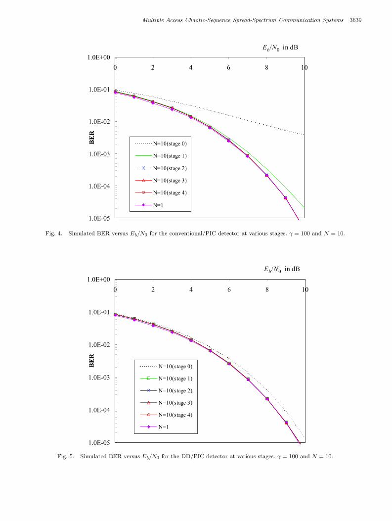
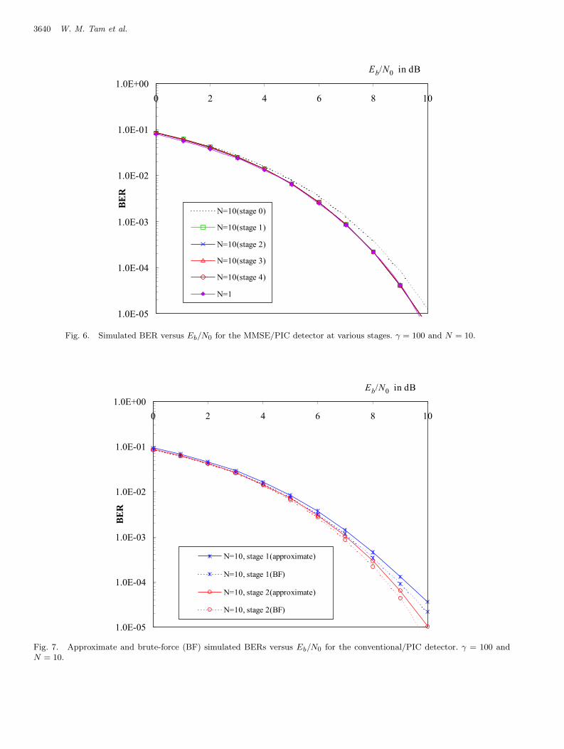
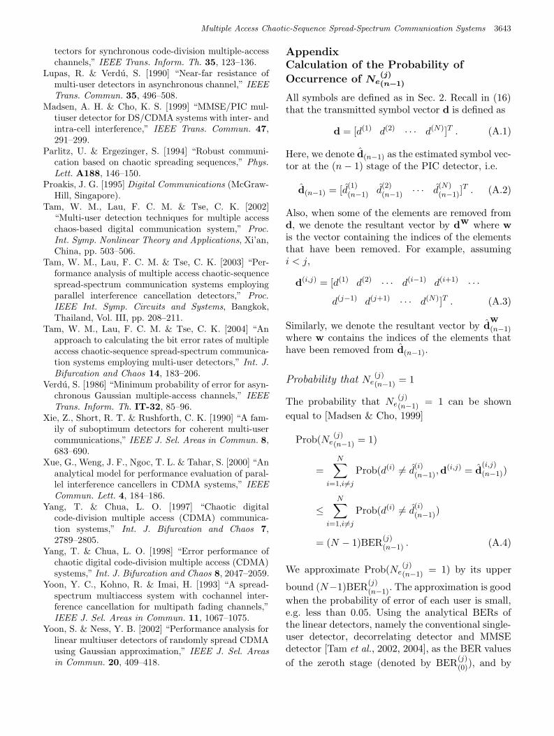
BERs for the conventional/PIC, DD/PIC andMMSE/PIC detectors, at various stages. The BERfor a single-user system, which is equivalent to aninterference-free system, is also given as a refer-ence. For all the detectors under study, the BERs atStage 1 are lower than those at Stage 0. For the con-ventional/PIC detector, the BER at Stage 2 is fur-ther reduced compared to that at Stage 1. The BERresults for the conventional/PIC detector with threestages, the DD/PIC and the MMSE/PIC detectorswith two stages, are close to that of the single-usersystem. When the number of stages is further in-creased, no improvement is observed. Overall, theresults indicate that the parallel interference can-cellation technique can further enhance the perfor-mance of linear multiuser detectors. With a lowBER at Stage 0 and at subsequent stages, it is welljustified that terms corresponding to large value ofu can be ignored in the computation of (25).
Figures 7 to 9 plot the approximate BERs(using (25)) and the brute-force (BF) simulatedBERs when the PIC detectors are applied. It canbe observed that the approximate and the simu-lated results agree with each other for all the PIC
October 27, 2004 13:29 01154
Multiple Access Chaotic-Sequence Spread-Spectrum Communication Systems 3639
Fig. 4. Simulated BER versus Eb/N0 for the conventional/PIC detector at various stages. γ = 100 and N = 10.
Fig. 5. Simulated BER versus Eb/N0 for the DD/PIC detector at various stages. γ = 100 and N = 10.
October 27, 2004 13:29 01154
3640 W. M. Tam et al.
Fig. 6. Simulated BER versus Eb/N0 for the MMSE/PIC detector at various stages. γ = 100 and N = 10.
Fig. 7. Approximate and brute-force (BF) simulated BERs versus Eb/N0 for the conventional/PIC detector. γ = 100 andN = 10.
October 27, 2004 13:29 01154
Multiple Access Chaotic-Sequence Spread-Spectrum Communication Systems 3641
Fig. 8. Approximate and brute-force (BF) simulated BERs versus Eb/N0 for the DD/PIC detector. γ = 100 and N = 10.
Fig. 9. Approximate and brute-force (BF) simulated BERs versus Eb/N0 for the MMSE/PIC detector. γ = 100 and N = 10.
October 27, 2004 13:29 01154
3642 W. M. Tam et al.
Fig. 10. Comparison of the conventional/PIC, DD/PIC and MMSE/PIC detectors. γ = 100 and N = 10.
detectors under study. Finally, we compared thesimulated BERs for the conventional/PIC, DD/PICand MMSE/PIC detectors. The results shown inFig. 10 indicate that the BERs for the DD/PICand MMSE/PIC detectors are almost the same. AtStage 1 of the PIC detector, the performances ofthe DD/PIC and MMSE/PIC detectors are betterthan that of the conventional/PIC detector. Withan additional stage (Stage 2), the conventional/PICcan achieve the same performance as the DD/PICand MMSE/PIC detectors.
4. Conclusion
In this Letter, we have applied three combinedlinear detector/parallel interference cancellation(PIC) detectors, namely conventional single-userdetector/PIC, decorrelating detector/PIC and min-imum mean-square-error/PIC detectors to a multi-ple access chaotic-sequence spread-spectrum com-munication system. The technique for deriving theapproximate BERs has been described. It is foundthat the approximate BERs agree with the simula-tion results. Also, it is shown that the PIC detectorscan further improve the bit error performance com-pared to that of the linear multiuser detectors. Withonly one or two PIC stages, the bit error perfor-
mance of the PIC detectors approaches to that ofa single-user (interference free) system. Increasingthe number of PIC stages further will not enhancethe bit error performance because the system is nowlimited by noise.
Acknowledgment
This work was supported by a Hong Kong Polytech-nic University Research Grant.
References
Arguello, F., Bugallo, M. & Amor, M. [2002] “Multi-userreceivers for spread spectrum communications basedon chaotic sequences,” Int. J. Bifurcation and Chaos
12, 847–853.Geisel, T. & Fairen, V. [1984] “Statistical properties
of chaos in Chebyshev maps,” Phys. Lett. A105,263–266.
Heidari-Bateni, G. & McGillem, C. D. [1994] “Achaotic direct-sequence spread-spectrum communica-tion system,” IEEE Trans. Commun. 42, 1524–1527.
Hui, A. L. C. & Letaief, K. B. [1998] “Successive in-terference cancellation for multiuser asynchronousDS/CDMA detectors in multipath fading links,”IEEE Trans. Commun. 46, 384–391.
Lupas, R. & Verdu, S. [1989] “Linear multi-user de-
October 27, 2004 13:29 01154
Multiple Access Chaotic-Sequence Spread-Spectrum Communication Systems 3643
Lupas, R. & Verdu, S. [1990] “Near-far resistance ofmulti-user detectors in asynchronous channel,” IEEE
Trans. Commun. 35, 496–508.Madsen, A. H. & Cho, K. S. [1999] “MMSE/PIC mul-
tiuser detector for DS/CDMA systems with inter- andintra-cell interference,” IEEE Trans. Commun. 47,291–299.
Parlitz, U. & Ergezinger, S. [1994] “Robust communi-cation based on chaotic spreading sequences,” Phys.
Lett. A188, 146–150.Proakis, J. G. [1995] Digital Communications (McGraw-
Hill, Singapore).Tam, W. M., Lau, F. C. M. & Tse, C. K. [2002]
“Multi-user detection techniques for multiple accesschaos-based digital communication system,” Proc.
Int. Symp. Nonlinear Theory and Applications, Xi’an,China, pp. 503–506.
Tam, W. M., Lau, F. C. M. & Tse, C. K. [2003] “Per-formance analysis of multiple access chaotic-sequencespread-spectrum communication systems employingparallel interference cancellation detectors,” Proc.
IEEE Int. Symp. Circuits and Systems, Bangkok,Thailand, Vol. III, pp. 208–211.
Tam, W. M., Lau, F. C. M. & Tse, C. K. [2004] “Anapproach to calculating the bit error rates of multipleaccess chaotic-sequence spread-spectrum communica-tion systems employing multi-user detectors,” Int. J.
Bifurcation and Chaos 14, 183–206.Verdu, S. [1986] “Minimum probability of error for asyn-
chronous Gaussian multiple-access channels,” IEEE
Trans. Inform. Th. IT-32, 85–96.Xie, Z., Short, R. T. & Rushforth, C. K. [1990] “A fam-
ily of suboptimum detectors for coherent multi-usercommunications,” IEEE J. Sel. Areas in Commun. 8,683–690.
Xue, G., Weng, J. F., Ngoc, T. L. & Tahar, S. [2000] “Ananalytical model for performance evaluation of paral-lel interference cancellers in CDMA systems,” IEEE
Commun. Lett. 4, 184–186.Yang, T. & Chua, L. O. [1997] “Chaotic digital
code-division multiple access (CDMA) communica-tion systems,” Int. J. Bifurcation and Chaos 7,2789–2805.
Yang, T. & Chua, L. O. [1998] “Error performance ofchaotic digital code-division multiple access (CDMA)systems,” Int. J. Bifurcation and Chaos 8, 2047–2059.
Yoon, Y. C., Kohno, R. & Imai, H. [1993] “A spread-spectrum multiaccess system with cochannel inter-ference cancellation for multipath fading channels,”IEEE J. Sel. Areas in Commun. 11, 1067–1075.
Yoon, S. & Ness, Y. B. [2002] “Performance analysis forlinear multiuser detectors of randomly spread CDMAusing Gaussian approximation,” IEEE J. Sel. Areas
in Commun. 20, 409–418.
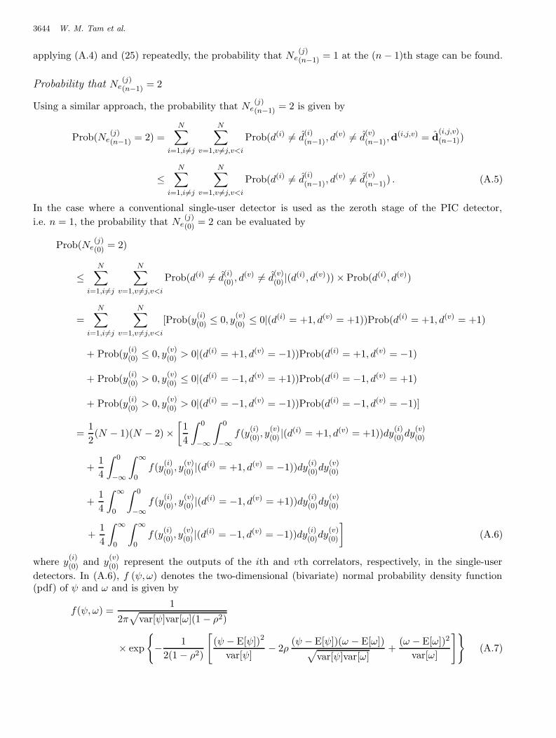
Appendix
Calculation of the Probability of
Occurrence of Ne(j)(n−1)
All symbols are defined as in Sec. 2. Recall in (16)that the transmitted symbol vector d is defined as
d = [d(1) d(2) · · · d(N)]T . (A.1)
Here, we denote d(n−1) as the estimated symbol vec-tor at the (n− 1) stage of the PIC detector, i.e.
d(n−1) = [d(1)(n−1) d
(2)(n−1) · · · d
(N)(n−1)]
T . (A.2)
Also, when some of the elements are removed fromd, we denote the resultant vector by dw where wis the vector containing the indices of the elementsthat have been removed. For example, assumingi < j,
d(i,j) = [d(1) d(2) · · · d(i−1) d(i+1) · · ·
d(j−1) d(j+1) · · · d(N)]T . (A.3)
Similarly, we denote the resultant vector by dw(n−1)
where w contains the indices of the elements thathave been removed from d(n−1).
Probability that Ne(j)(n−1) = 1
The probability that Ne(j)(n−1) = 1 can be shown
equal to [Madsen & Cho, 1999]
Prob(Ne(j)(n−1) = 1)
=
N∑
i=1,i6=j
Prob(d(i) 6= d(i)(n−1),d
(i,j) = d(i,j)(n−1))
≤
N∑
i=1,i6=j
Prob(d(i) 6= d(i)(n−1))
= (N − 1)BER(j)(n−1) . (A.4)
We approximate Prob(Ne(j)(n−1) = 1) by its upper
bound (N−1)BER(j)(n−1). The approximation is good
when the probability of error of each user is small,e.g. less than 0.05. Using the analytical BERs ofthe linear detectors, namely the conventional single-user detector, decorrelating detector and MMSEdetector [Tam et al., 2002, 2004], as the BER values
of the zeroth stage (denoted by BER(j)(0)), and by
October 27, 2004 13:29 01154
3644 W. M. Tam et al.
applying (A.4) and (25) repeatedly, the probability that Ne(j)(n−1) = 1 at the (n− 1)th stage can be found.
Probability that Ne(j)(n−1) = 2
Using a similar approach, the probability that Ne(j)(n−1) = 2 is given by
Prob(Ne(j)(n−1) = 2) =
N∑
i=1,i6=j
N∑
v=1,v 6=j,v<i
Prob(d(i) 6= d(i)(n−1), d
(v) 6= d(v)(n−1),d
(i,j,v) = d(i,j,v)(n−1))
≤
N∑
i=1,i6=j
N∑
v=1,v 6=j,v<i
Prob(d(i) 6= d(i)(n−1), d
(v) 6= d(v)(n−1)) . (A.5)
In the case where a conventional single-user detector is used as the zeroth stage of the PIC detector,
i.e. n = 1, the probability that Ne(j)(0) = 2 can be evaluated by
(v)(0) represent the outputs of the ith and vth correlators, respectively, in the single-user
detectors. In (A.6), f (ψ, ω) denotes the two-dimensional (bivariate) normal probability density function(pdf) of ψ and ω and is given by
f(ψ, ω) =1
2π√
var[ψ]var[ω](1 − ρ2)
× exp
{
−1
2(1 − ρ2)
[
(ψ − E[ψ])2
var[ψ]− 2ρ
(ψ − E[ψ])(ω − E[ω])√
var[ψ]var[ω]+
(ω − E[ω])2
var[ω]
]}
(A.7)
October 27, 2004 13:29 01154
Multiple Access Chaotic-Sequence Spread-Spectrum Communication Systems 3645
where ρ is the correlation coefficient between ψ and ω, and is defined as
ρ =E[ψω] − E[ψ]E[ω]√
var[ψ]var[ω]. (A.8)
It is readily shown that∫ 0
−∞
∫ 0
−∞f(y
(i)(0), y
(v)(0) |(d
(i) = +1, d(v) = +1))dy(i)(0)dy
(v)(0)
=
∫ 0
−∞
∫ ∞
0f(y
(i)(0), y
(v)(0) |(d
(i) = +1, d(v) = −1))dy(i)(0)dy
(v)(0)
=
∫ ∞
0
∫ 0
−∞f(y
(i)(0), y
(v)(0) |(d
(i) = −1, d(v) = +1))dy(i)(0)dy
(v)(0)
=
∫ ∞
0
∫ ∞
0f(y
(i)(0), y
(v)(0) |(d
(i) = −1, d(v) = −1))dy(i)(0)dy
(v)(0) . (A.9)
Hence, Prob(Ne(j)(0)
= 2) can be simplified to
Prob(Ne(j)(0)
= 2) ≤1
2(N − 1)(N − 2)
∫ 0
−∞
∫ 0
−∞f(y
(i)(0), y
(v)(0)
|(d(i) = +1, d(v) = +1))dy(i)(0)dy
(v)(0). (A.10)
Similar to the case for Ne(j)(n−1) = 1, we approximate Prob
(
Ne(j)(0) = 2
)
by its upper bound given in (A.10).
Probability that Ne(j)(n−1) ≥ 3
The probability that Ne(j)(n−1) ≥ 3 is given by
Prob(Ne(j)(n−1) = u) =
∑
j /∈u∪u,
∑
u∩u=�,
· · ·∑
u∪u∪j={1,2,...,N}
Prob(d(j,u)(n−1) 6= d
(j,u)(n−1),d
(j,u)(n−1) = d
(j,u)(n−1))
≤∑
j /∈u∪u,
∑
u∩u=�,
· · ·∑
u∪u∪j={1,2,...,N}
Prob(d(j,u)(n−1) 6= d
(j,u)
(n−1)) (A.11)
where the vectors u and u contain the indices of theusers that have made, respectively, wrong decisionsand correct decisions. Using similar procedures as in
the case Ne(j)(n−1) = 2, if a conventional single-user
detector is used as the zeroth stage, the probability
that Ne(j)(0) ≥ 3 can be shown equal to
Prob(Ne(j)(0)
= u) ≤
(
N − 1
u
)∑
d′
∈{−1,+1}u
∫
y(u)(0)
· · ·
∫
y(2)(0)
∫
y(1)(0)
f(Y|d′)dy(1)(0)dy
(2)(0)
· · · dy(u)(0) × Prob(d′) (A.12)
where
(wv
)
denotes the number of ways to choose
v items out of w. Also, the vectors Y and d′ are
defined as
Y = [y(1)(0) y
(2)(0) · · · y
(u)(0) ]
T (A.13)
d′ = [d(1) d(2) · · · d(u)]T . (A.14)
The u-dimensional normal pdf of Y for a given vec-tor d′ is denoted by f(Y|d′). It is represented by
f(ψ) =1
√
(2π)u det[U]
× exp
[
−1
2(ψ − E[ψ])T U−1(ψ − E[ψ])
]
(A.15)
where
ψ = [ψ(1) ψ(2) · · · ψ(u)]T , (A.16)
October 27, 2004 13:29 01154
3646 W. M. Tam et al.
U−1 is the u × u covariance matrix of the randomvariables ψ(1), ψ(2), . . . , ψ(u), and det[·] denotes thedeterminant operator.
Probability that Ne(j)(n−1)
= 0
SinceN−1∑
m=0
Prob(Ne(j)(n−1) = m) = 1 , (A.17)
the probability that Ne(j)(n−1) = 0 can be evaluated


![UAV Communications Based on Non-Orthogonal Multiple Access - … · 2018-09-18 · arXiv:1809.05767v1 [eess.SP] 15 Sep 2018 1 UAV Communications Based on Non-Orthogonal Multiple Access](https://static.documents.pub/doc/80x56/5e69512921d98d64ab48758e/uav-communications-based-on-non-orthogonal-multiple-access-2018-09-18-arxiv180905767v1.jpg)


