PERFORMANCE A N D ANALYSIS OF SEALS FOR INERTED LUBRICATION SYSTEMS OF TURBINE ENGINES by Robert L. Johnson, William R. Loomis, and Luwrence P. Ladwig !- Lewis Research Center CZeueZand, Ohio NATIONAL AERONAUTICS AND SPACE ADMINISTRATION WASHINGTON, D. C. AUGUST 1968
Transcript
PERFORMANCE A N D ANALYSIS OF SEALS FOR INERTED LUBRICATION SYSTEMS OF TURBINE ENGINES
by Robert L. Johnson, William R. Loomis, and Luwrence P. Ladwig !-
Lewis Research Center CZeueZand, Ohio
NATIONAL AERONAUTICS AND SPACE ADMINISTRATION WASHINGTON, D. C. AUGUST 1968
I -- -
TECH LIBRARY KAFB, NM
NASA T N D-4761
PERFORMANCE AND ANALYSIS O F SEALS FOR INERTED
LUBRICATION SYSTEMS OF TURBINE ENGINES
By Rober t L. Johnson, Wi l l iam R. Loomis , and L a w r e n c e P. Ludwig
Lewis R e s e a r c h C e n t e r Cleveland, Ohio
NATIONAL AERONAUT ICs AND SPACE ADMINISTRATION
For sale by the Clearinghouse for Federal Scientific and Technical Information Springfield, Virginia 22151 - CFSTl price $3.00
ABSTRACT
An inerted lubricating system incorporating a 125-millimeter ball bearing and 6.33- inch- (161-mm-) diameter face contact sea ls was operated for short duration screening runs in a simulated turbine engine sump at speeds to 14 000 rpm and bulk oil tempera- tu res to 500' F (533 K). outer race temperature under a 3280-pound (14 590 N) thrust load with four of the five lubricants evaluated in these short time runs. A persistent problem encountered was wear and leakage of the shaft seals. Additional experimental studies and analysis identi- fied seal thermal deformation a s a major factor in seal wear and leakage. New seals , revised to mitigate thermal deformations, were designed, analyzed, and subjected to preliminary experimental studies.
The ball bearings operated satisfactorily to 600' F (589 K)
ii
I '
PERFORMANCE AND ANALYSIS OF SEALS FOR INERTED
LUBRICATION SYSTEMS OF TURBINE ENGINES*
by Robert L. Johnson, William R. Loomis, and Lawrence P. Ludwig
Lewis Research Center
SUMMARY
A nitrogen inerted lubricating system incorporating a 125-millimeter ball bearing and 6. 33-inch- (161-mm-) diameter face contact seals was operated in a simulated tur- bine engine sump to 14 000 rpm to explore system feasibility and to identify system prob- lems. The bearing had a DN value of 1.75X10 and a maximum Hertz s t r e s s of 197 000 psi (136 000 N/cm2). In these 3-hour screening tests, with degassed lubricants at a bulk fluid temperature of 500' F (533 K), the dibasic acid ester (MIL-L-7808E) did not provide adequate bearing lubrication at 600' F (589 K) outer race bearing temperature. Three lubricants, an improved ester, a synthetic paraffin and a perfluorinated polymeric fluid were used in other screening tes ts to 700' F (644 K) outer race temperature and, in each case, the bearings showed no deterioration from the short time running. A modified polyphenyl ether (C-ether) lubricant performed satisfactorily with 600' F (589 K) outer race bearing temperature both with and without nitrogen inerting.
bellows type face contact seal separating the nitrogen gas and oil. Analysis revealed that the seal problems (excessive gas leakage and w e a r ) were not related to the inerting gas but rather to seal thermal deformation. Further experiments, on contact and hydrostatic type seals in another simulated engine sump without inerting, showed that thermal defor- mations were a major factor in limiting seal performance.
devices, were designed, analyzed, and checked experimentally. One revised design em- ployed a hydrodynamic gas bearing for lift, and the other obtained lift by means of an oil lubricated spiral groove bearing. Both of these revised designs showed low leakage po- tential in preliminary tests.
6
In inerted lubrication system operation, the most troublesome component w a s the
Two seals, revised to minimize thermal gradients and employing hydrodynamic lift
* Presented at ASME Gas Turbine Conference and Products Show, Washington, D. C. , March 17-21, 1968.
INTRODUCTION
Continuing increases in flight speeds and turbine inlet temperatures are raising the bulk temperatures of lubricating systems in aircraft turbine engines (refs. 1 and 2). The ester base synthetic lubricants of conventional lubricating systems have little o r no mar- gin to cope with higher temperatures (ref. 2). Therefore, not only is there an immediate need for improved lubricants and lubricating systems in uprated engines, but advanced engines, such as for Mach 3 flight, pose a much larger lubrication system problem be- cause bulk lubricant temperatures are expected to be in the 450' to 500' F (505 to 533 K) range.
In seeking solutions to this general problem of high temperature lubrication, some attention has been given to unconventional systems such as powder lubrication (ref. 3), dry fi lms (ref. 4), and throwaway schemes. Another unconventional approach is based on oxygen exclusion through the use of an inert gas blanket (e. g. , nitrogen). Oxidation is the primary limitation for lubricants at high temperatures. The inerted lubrication system approach is attractive because it may permit the use of presently available lubri- cants at significantly higher temperature levels. If oxygen is eliminated, bulk fluid tem- peratures for lubricants can be increased without significant chemical changes.
amount of blanket gas inventory depends on leakage rates. Low leakage precludes the use of labyrinth seals and places stringent requirements on the seal design since long life and low leakage must both be achieved. The size of seals is particularly important to performance, and the use of full-scale hardware is essential for obtaining meaningful data. There is some evidence (ref. 5) that seal carbon life will be enhanced through the use of nitrogen inerting. These data (ref. 5) show that the carbon wear ra te is lower in nitrogen and that oxidation is the chief cause of higher wear ra tes in air.
The objectives of this study were as follows: (1) to determine such problems as can be established in short-term operation of lubricants, bearing and seals in a full-size simulated engine sump at speeds, pressures, and temperatures expected in advanced en- gines; (2) to determine the leakage rates of these full-size seals operating in an inerted bearing sump system; and (3) to investigate newer seal concepts and to check the feasi- bility of these concepts experimentally.
The simulated engine sump of the inerted lubrication system incorporated a 6.33- inch- (161-mm-) diameter face contact and a 125-millimeter ball bearing operating at 14 000 rpm with a 3280-pound (14 590-N) thrust load. Thus, the bearing had a DN value of 1.75xlO and a maximum Hertz stress at 197 000 psi (136 000 N/cm ). Runs were made with a nominal bulk fluid temperature of 500' F (533 K) with outer race bearing temperatures between 600' and 750' F (589 and 672 K) and with nominal 100-psi (69- N/cm ) pressure differential across the nitrogen gas to oil seal. Nominal seal surface
A key factor in the use of inerted lubricant systems is seal leakage, because the
6 2
2
2
speed was 400 feet per second (122 m/sec). The initial bearings and seals were ad- vanced state of the art components selected from different engine development programs. Neither the bearings nor the seals were designed to operate under temperature conditions as severe as imposed by this program. Only minor modifications to those par ts (e. g . , bearing cage clearance) were made for this exploratory operation.
Another simulated engine bearing sump operating with air (not inerted) was used to evaluate seal concepts. This system contained bearings from turbine engines (a 130-mm roller bearing and a 110-mm duplex thrust bearing). The air to oil seals were operated at pressure differentials to 300 psi (207 N/cm ) and at speeds to 400 feet per second (122 m/sec). Sealed air temperatures to 1200' F (922 K) were employed.
Analytical studies were made to determine thermal gradients in the seal structure and to determine overall elastic deformation due to temperature, pressure, and centrifu- gal force.
2
Part of the studies reported herein were made under NASA contracts (refs. 6 to 9).
APPARATUS AND PROCEDURE
lnerted Lubrication Systems
A schematic of the simulated turbine engine sump employing an inerted lubricating system is shown in figure 1. The r ig incorporated a 125-millimeter ball bearing and was operated at 14 000 rpm. Heaters on the bearing and housing outside diameter permitted
Nitrogen to a i r sealJ I Nitrogen to oi l seal-' I
Figure 1. - Bearing and seal assembly in simulated engine sump, iner ted lubr icat ion system.
3
I
operation to 750' F (672 K) bearing outer race temperature. Lubricants were introduced at a nominal temperature of 500' F (533 K). Two face contact seals (bellows secondary) formed the sealing system. Nitrogen was introduced between the two seals at 105 psig (72.4 N/cm g). The seal between the nitrogen gas and bearing sump, therefore, was subjected to a 100-psi (69-N/cm ) pressure differential, and the seal between the hot air (1200' F (922 K) and 100-psi (69-N/em2)) and nitrogen was subjected to a 5-psi (3- N/cm2) pressure differential.
2 2
m e r
F C l o s i n g I c*...-*
diameter Nosepiece h ' v e n t d '
Nitrogen gas, 105 psig (72 N/cm2g)(P,)
Figure 2 is a schematic of the seal employed in the inerted lubrication systems. The bellows assembly was fabricated from Inconel. A finger spring damper, rubbing against the nosepiece retainer outside diameter, provided friction damping. The carbon- graphite nosepiece face contained three elements - an outer wear pad, a sealing dam, and an inner wear pad. The wear pads were interrupted by grooves that vented the wear pad area. Thus, the pressure drop occurred only across the sealing dam. The seal seat w a s chrome plated on the rubbing surface and finished flat within three light bands.
graphite nosepiece and seal seat were made by inspection after running. In some cases surface profile t races were made to determine effect of sealing face deformation on con- tact area. Other parameters recorded included sealed gas pressure and temperature, sliding speed, lubricant temperatures, and bearing outer race temperature.
The test bearing, a split-inner-ring angular-contact ball bearing, is the type most widely used in aircraft turbine engines. This design permits a maximum ball comple- ment (because of separable inner ring halves) and supports a thrust load in either direc-
Seal gas leakage was monitored continuously. Wear measurements of the carbon-
4
r -
tion. The separa'me 'ring also permits the use of a precision-machined one-piece cage which is required for high-speed high-temperature operation. The test bearing has a bore diameter of 125 millimeters and a nominal mounted operating contact angle of 26'. This bearing runs at the test speed of 14 000 rpm (DN = 1.75X10 ) and a thrust load P of 3280 pounds (14 590 N) (maximum Hertz surface stress, 197 000 psi (136 000 N/cm2)). For operating temperatures up to 600' F (589 K), consumable electrode vacuum melted (CVM) M-50 tool steel rings and balls were used. At higher temperatures, CVM WB49 tool steel was used for the bearing rings and CVM M-1 tool steel for the balls. The cages are of an outer-ring piloted design and were constructed of silver plated M-1 tool steel. The bearings had a nominal 51.6-percent inner ring conformity, a 52. l-percent outer ring conformity, a surface roughness of 4-microinch (0.102-pm) r m s maximum across grooves, twenty-one 13/16-inch- (2.064-cm-) diameter balls, and a 0.0068- to 0.0080-inch (0.0173- to 0.0203-cm) unmounted internal radial looseness.
6
The following were the lubricants used: (1) Formulated dibasic acid es te r (MIL-L-7808E type) with proprietary additives
(2) Mixed ester-base lubricant with improved thermal stability and with an estimated
(3) Synthetic paraffinic lubricant containing a proprietary boundary lubricant additive
(4) Unformulated perfluorinated polymer (fluorocarbon) with an estimated viscosity
(5) Unformulated modified polyphenyl ether (aromatic C -ether) having 0. 6 centistoke
Pr ior to test all lubricants were degassed for 72 hours at room temperature at a nominal pressure of millimeter of mercury.
and with an extrapolated viscosity of 0.64 centistoke at 600' F (589 K)
viscosity of 1. 17 centistokes at 600' F (589 K)
and having an estimated viscosity of 2.4 centistokes at 600' F (589 K)
of 1 . 6 centistokes at 600' F (589 K)
estimated viscosity at 600' F (589 K)
Seal Concept Studies
Figure 3 is a schematic of the seal and bearing area of a simulated turbine engine sump employing an open lubrication system and used to study face contact and hydro- static seal concepts. The system simulated the roller bearing sump at the turbine loca- tion and the structure is typical of engine parts. High pressure air at temperatures to 1200' F (922 K) was introduced at the seal dam inside diameter and air leakage was into the bearing compartment. Seal gas leakage w a s monitored continuously. W e a r measure- ments of the sealing faces were provided by inspection after running. Other parameters recorded included sealed gas pressure and temperature, rpm, lubricant temperature, and seal nosepiece temperature. In some runs accelerometers were attached to the
5
I
Shaft _I
F igure 3. - Bearing and seal assembly in simulated open engine sump used to evaluate face contact and hydrostatic seals.
nosepiece, and accelerometer output was recorded on magnetic tape and then analyzed qualitatively for evidence of nosepiece instability.
the seal assembly by a finite-difference steady-state heat-transfer computer program. Thermal deformation was calculated from these thermal maps by an axisymmetric finite- element computer program, which also included pressure and centrifugal force effects.
Analysis of sealing face deformation was made by first calculating a thermal map of
RESULTS AND DISCUSSION
I nerted Lubrication System
Lubricants. - Operation of a furl-scale simulated lubrication system (bearing and seals) allows evaluation of a lubricant at temperatures, shear rates, and loads which are indicative of actual conditions. Thus a check is obtained on such items as coking, lubri- cant breakdown due to shear rates, lubricant effectiveness at bearing cage sliding sur- face, corrosion, seal performance, etc. The durations of these runs were not sdficient to show potential problems that might accrue from extended operation with partial lubri- cant films. Such discontinuous films might be expected at the high surface temperatures for the bearing and oil seals of these runs. The lubrication system, which is described in the apparatus section, simulated the expected environmental conditions of an inerted
6
bearing sump of an advanced engine. The lubricants evaluated, also described in the ap- paratus section, were as follows: (1) a dibasic acid ester qualifying against MIL-L- 78083, (2) an improved higher viscosity mixed ester formulation, (3) a synthetic paraf- finic lubricant, (4) a modified polyphenyl ether (C-ether), and (5) a perfluorinated poly- meric fluid. All lubricants were degassed before use for 72 hours at 75' F (297 K) and a nominal pressure of
Pr imary results obtained for these lubricants in the system studies (3-hr screening tests) are as follows:
(1) The dibasic acid ester (MIL-L-78083 type) lubricant did not provide adequate bearing lubrication, even with inert blanketing, at 600' F (589 K) outer race bearing temperatures. Lubrication-related bearing distress, including excessive wear of the cage and balls, occurred. Also, isoteniscope data show thermal breakdown of the for- mulation at 575' F (575 K).
ester (MIL-L-78083) ran satisfactorily in tes ts with an outer race bearing temperature as high as 700' F (644 I(). At a 650' F (616 K) bearing temperature, this fluid per- formed satisfactorily for approximately 10 hours before testing was stopped due to a seal malfunction.
(3) The synthetic paraffinic lubricant was used satisfactorily to outer race bearing temperatures of 700' F (644 K). An attempted run at 750' F (672 K) was aborted after less than 2 hours because of excessive leakage of the oil-side test seal.
(4) The modified polyphenyl ether (C-ether) performed satisfactorily at 600' F (589 K) both with and without nitrogen blanketing. Higher temperature testing was sus- pended because it was necessary to provide oil flows greater than considered practical to stabilize the bearing temperatures at 600' F (589 K).
(5) Perfluorinated polymeric fluid w a s run successfully to bearing temperatures of 700' F (644 K) but higher lubricant flow rates were required to achieve temperature sta- bility than for the improved ester o r the synthetic paraffinic lubricants.
Only minor oil coking occurred in most tes ts and usually did not appear to affect bearing o r seal performance seriously. Attempted runs of 50 hours with the improved ester and the synthetic paraffinic were not completed due to repeated oil-side seal mal- functions, which was also the limiting factor in a majority of the 3-hour screening tests.
From the overall system viewpoint, based on short-term tests, bearing and seal operation using inerted recirculating lubrication appears to be feasible at 150' to 200' F (339 to 366 K) higher bulk oil temperatures than possible with a conventional recirculating system with several off -the-shelf fluids. For example, in an open system, a diester based fluid would not be considered at bulk oil temperatures over 350' F (450 K), but isoteniscope data showed it was thermally stable to 575' F (575 K) in the absence of air.
niillimeter of mercury.
(2) An improved mixed ester of somewhat greater viscosity than the dibasic acid
7
I
The primary problem in the inerted system is related to achieving low leakage oil-seal performance so that leakage loss of inerting gas would be tolerable in a flight vehicle.
gas but rather to thermal deformation. Seal leakage data are summarized in table I. Seals. - Analysis revealed that the seal malfunctions were not related to the inerting
TABLE I. - FACE CONTACT SEAL LEAKAGE IN INERTED LUBRICATION SYSTEMS
[Seal mean diameter, 6.33 in. (161 mm); sliding speed, 395 ft/sec (120 m/sec); pressure differential, 100 psi (69 N/cm2).]
Fluid type r Formulated dibasic acid ester I
Formulated mixed ester base
Formulated synthetic paraffinic
Unformulated perfluor inat ed polymer
I
Unformulated modified poly- phenyl ether
~
Rw
1 9 2
~
3 4 5 6
7 8
9
10 11
12
13
14 ~
Run tim€ hr
3.7
3.3 3.3 3.4 9 .7
3.2 2.5
6.5
3.0 3.7
3.7
1.0
3.0
Bulk oil temperature
O F
490 to 55:
480 to 50C 450 to 50C 495 to 50C 475 to 520
480 to 550 450 t o 550
480 to 500
500 to 505 500 to 510
490 to 510
$80 to 500
190 to 515
K
528 to 5 6 ~
523 to 53: 505 to 532 530 to 53: 519 to 544
523 to 561 505 to 561
523 to 533
533 t o 536 533 to 539
528 to 539
523 to 533
528 to 541
Bearing outer race temperature
O F
540 to 60C
590 to 675 600 to 700 730 to 750 610 to 640
560 to 625 550 to 600
675 to 760
310 to 615 390 to 780
500 t o 740
580 to 600
$00 to 620
K
555 to 58:
583 to 63[ 589 to 644 661 to 67; 594 to 611
566 to 603 561 to 58s
630 to 678
594 to 597 639 to 689
589 to 666
578 to 589
589 to 600
Seal leakage rate
Standard ft3/min
0.7 to 1.5
6 to 8 10 to 11 1 to 3 6 to 26
3.7 to 4.4 6.9 to 20.7
3 . 9 t 0 4 . 9
10 to 13 15 to 23
5 to 10
1.0
7 to 11
Standard m3/hr
1 . 2 to 2.6
10 to 14 17 to 19
1.7 to 5 . 1 10 to 43
6.3 to 7.5 15. I to 35.
1. 5 to 8. 3
17 t o 22 25 to 39
8. 5 to 17
1 . 7
11 to 19
Remarks
Test bearing failure
Run completed Run completed Run completed O i l seal left ofi
Run completed Excessive seal
leakage Seal failure
Run completed Excessive seal
leakage rest bearing
failure
rest bearing
Zun completed failure
3 The data show that seal leakage, for the majority of runs, is greater (5 standard f t /min 3 (8.5 m /hr) or more) than would likely be acceptable from a nitrogen inventory stand-
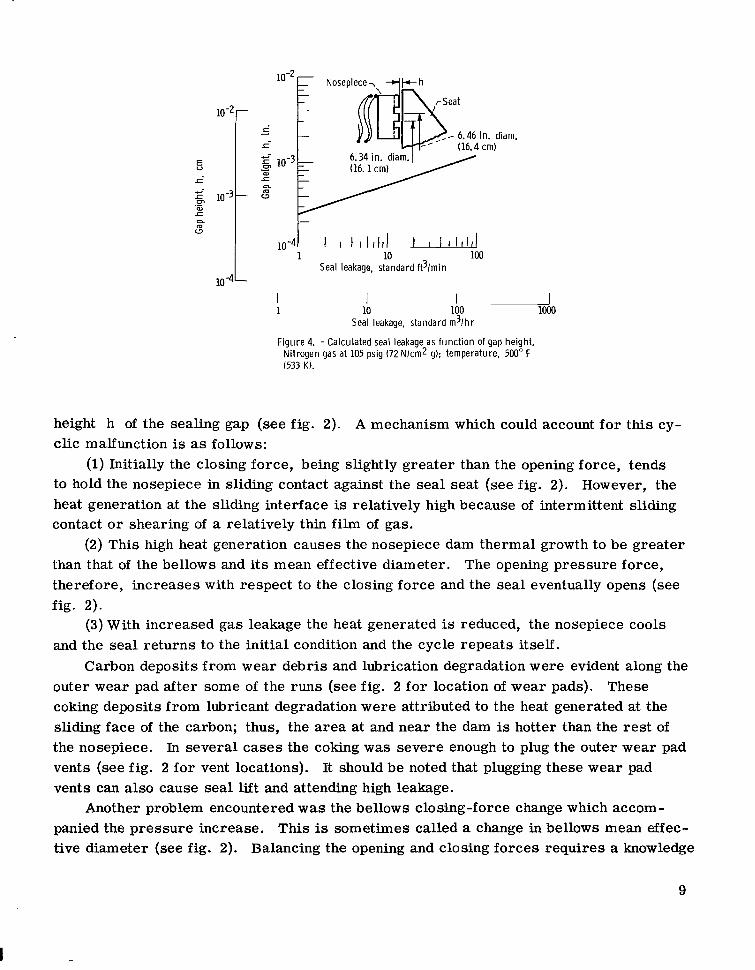
point. The leakage shown is a total for both seals (oil and air seals of fig. 1) in the sys- tem; however, it was determined that most of the leakage (up to 90 percent) could be at- tributed to the oil seal. (See fig. 4 for calculated seal leakage as a function of gap height. )
crease in leakage. This cyclic change in leakage implies a cyclic change in the average One seal malfunction that commonly occurred was a cyclic increase and then de-
8
E- I
.- E-
n m
Nosepiece-,, A k h
- m ,"
10-4[ I I I I I I I I l & 10 100
Seal leakage, standard ft3/min 10-4 -
100 lo00 I I 1 10
Seal leakage, standard m3/hr
Figure 4. - Calculated seal leakage as funct ion of gap height. Nitrogen gas at 105 psig (72 N / c d 9); temperature, 500" F 1533 K).
height h of the sealing gap (see fig. 2). A mechanism which could account for this cy- clic malfunction is as follows:
to hold the nosepiece in sliding contact against the seal seat (see fig. 2). However, the heat generation at the sliding interface is relatively high because of intermittent sliding contact or shearing of a relatively thin film of gas.
than that of the bellows and its mean effective diameter. therefore, increases with respect to the closing force and the seal eventually opens (see fig. 2).
and the seal returns to the initial condition and the cycle repeats itself.
outer wear pad after some of the runs (see fig. 2 for location of wear pads). These coking deposits from lubricant degradation were attributed to the heat generated at the sliding face of the carbon; thus, the area at and near the dam is hotter than the rest of the nosepiece. In several cases the coking was severe enough to plug the outer wear pad vents (see fig. 2 for vent locations). It should be noted that plugging these wear pad vents can also cause seal lift and attending high leakage.
panied the pressure increase. This is sometimes called a change in bellows mean effec- tive diameter (see fig. 2). Balancing the opening and closing forces requires a knowledge
(1) Initially the closing force, being slightly greater than the opening force, tends
(2) This high heat generation causes the nosepiece dam thermal growth to be greater The opening pressure force,
(3) With increased gas leakage the heat generated is reduced, the nosepiece cools
Carbon deposits from wear debris and lubrication degradation were evident along the
Another problem encountered w a s the bellows closing-force change which accom-
9
of this mean effective diameter change and of the probable pressure profiles at the seal- ing dam. At best, the selected force balance was a compromise, and a slight closing force was selected at test pressure in order to preclude opening the sliding interface (dam) due to inertia forces. Carbon wear encountered in some of the tests with increased loading was attributed to the lack of control over this seal force balance.
Evaluation of Seal Concepts in an Open Lubrication System
Face contact and hydrostatic seal concepts were evaluated in a simulated engine sump operating with an air environment (not inerted). The face contact seal used oper- ates on the same principle as the seal previously described for the inerted system except
~ I I I I I I I 0 Static -before test
L 0 200 ftlsec: 61 mlsec (6 820 rpm)
0 400 ft lsec; 122 mlsec (13 640 rpm)
0 20 40 60 80 100 120 140 160 180 200 220 240 Pressure drop across seal, psi
0
I I I I I I I I I J 0 20 40 60 80 100 120 140 160 180
Pressure drop across seal, N k m 2
Figure 5. - Face contact seal leakage (piston r i n g secondary), open lubrication system. Sealed a i r temperature, 800' F (700 K).
that the bellows is replaced with two piston rings and a ser ies of helical springs (fig. 5). It is evident from table II, which is a summary of the test data, that seal leakage was the primary failure mode. Additional data, characteristic of the leakage ra tes of these seals, are given in figure 5. is relatively low (being less than 5 standard f t /min (8. 5 m /hr)); beyond 120 psi (82.7 N/cm ) the leakage rate shows a strong dependence on sliding speed. This dependence of leakage on sliding speed could be caused by (1) a nosepiece dynamic response to seat
Up to 120 psi (82.7 N/cm2) pressure differential the leakage rate 3 3
2
10
TABLE 11. - FACE CONTACT SEAL PERFORMANCE IN OPEN LUBRICATION SYSTEM
[Seal mean diameter, 6.80 in. (172.7 mm); sliding speeds, 200 to 400 ft /sec (61 to 122 m/sec).]
iUn
-
1
2
3
4
5
6
7
RUn time, h r
16
50
5 . 1
9 .7
14.7
01.7
57.1
Nosepiece wear
in.
0.0002
0.0256
0.0006
0.0020
0.0025
0.0022
____- -
~
cm
0.0005
0.0650
0.0015
0.0051
0.0064
0.0056
- - _ _ _ -
Sealed air temperature
OF
70
70 800
800
800 1000
800 1230
800 1200
800 1200
K
294
294 700
700
700 811
700 943
700 922
700 922
Reason f o r run termination
~
High seal leakage of 58 standard 3 ft3/min (99 m /hr) at 140 ps i
(96.5 N/cm2)
High seal leakage of 46 standard
(172 N/cm2)
High seal leakage of 30 standard ft3/min (51 m3/hr) at 120 ps i (82.7 N/cm2)
High sea l leakage of 40 standard f t /min (68 m /hr ) a t 160 psi (110 N/cm2)
ft3/min (78 m 3 /hr) at 250 ps i
3 3
High sea l leakage of 32 standard ft3/min (54 m3/hr) a t 40 ps i (27.6 N/cm2)
Run completed
Sump f i r e due to sea l failure
runout and rotation, (2) thermal effects such as described for the bellows face seal, (3) separation of the sealing surfaces by greater volume or size of wear particles, and (4) instabilities induced by stick-slip friction phenomena.
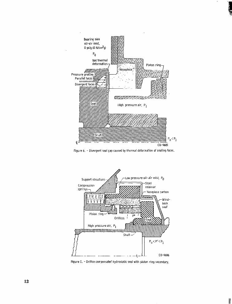
mal deformation of the nosepiece and seal seat. This thermal deformation, illustrated in figure 6, was identified by both wear patterns and thermal analysis. The axial thermal gradients cause both the nosepiece and seal seat to form divergent leakage gaps. A di- verging gap reduces the seal opening force and causes the net closing force to increase. The result is heavy carbon wear at the nosepiece inside diameter.
A second concept evaluated w a s an orifice-compensated hydrostatic seal design which operates on an air film of about 0.0005 inch (0.00127 cm). The seal design (fig. 7) is somewhat similar to that of a face contact seal except that a recess and a series of
An additional problem associated with operation of the face contact seal was the ther- .
11
Bearing side oi l -a i r mist,
P I
0 psig (0 N/cm2g)
CD-9685
Figure 6. - Divergent seal gap caused by thermal deformation of sealing faces.
Figure 7. - Ori f ice compensated hydrostatic seal with piston r i n g secondary.
12
I '
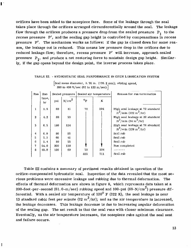
orifices have been added to the nosepiece face. Some of the leakage through the seal takes place through the orifices arranged circumferentially around the seal. The leakage flow through the orifices produces a pressure drop from the sealed pressure P1 to the recess pressure P', and the sealing gap height is controlled by compensations in recess pressure P'. The mechanism works as follows: if the gap is closed down for some rea- son, the leakage out is reduced. This means low pressure drop in the orifices due to reduced leakage flow; therefore, recess pressure P' will increase, approach sealed pressure PI, and produce a net restoring force to maintain design gap height. Similar- ly, if the gap opens beyond the design point, the inverse process takes place.
TABLE ID. - HYDROSTATIC SEAL PERFORMANCE I N OPEN LUBRICATION SYSTEM
[Seal mean diameter, 6.70 in. (170.2 mm); sliding speed, 200 to 400 ft /sec (61 to 122 m/sec).]
RUn
1
2
3
4 5 6 7 8
Run time,
h r
1. 5
4.2
6 .5
6. 0 7.3 5 . 4
54.0 49.0
Sealed p res su re
ps i
60
80
180
80 60 80
200 100
N/cm2
41
55
124
55 41 55
138 69
Sealed air temperature Reason f o r run termination
~
High seal leakage at 72 standard
High seal leakage a t 20 standard
High seal leakage at 76 standard
Seal rub Seal rub Seal rub Run completed
Seal rub
ft3/min (122 m3/hr)
ft3/min (34 m3/hr)
ft3/min (129 m 3 /hr)
- - - - - - -
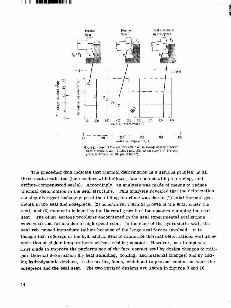
Table III contains a summary of pertinent results obtained in operation of the orifice-compensated hydrostatic seal. Inspection of the data revealed that the most se- rious problems were excessive leakage and rubbing due to thermal deformation. The effects of thermal deformation are shown in figure 8, which represents data taken at a 200-foot-per-second (61.O-m/sec) rubbing speed and 100-psi (69-N/cm ) pressure dif- ferential. With a sealed air temperature of 120' F (322 K), the seal leakage is near 13 standard cubic feet per minute (22 m /hr); and as the air temperature is increased, the leakage decreases. This leakage decrease is due to increasing angular deformation of the sealing gap. The net result is that the seal runs with closer minimum clearance. Eventually, as the air temperature increases, the nosepiece rubs against the seal seat and failure occurs.
2
3
13
PO
L ._
Paral lel Divergent Seal r u b caused faces faces by divergence
I I -
c 73 L
g 10 c m c VI 0 0
H 5 J 0 a-
m a
L - 2
0 100 200 300 400 500 600 700 800 900
Sealed a i r temperature, "F
~. J 800
1 700
I - L - I . . I 300 400 500 600
Sealed a i r temperature, K
Figure 8. - Effect of thermal deformation on a i r leakage of o r i f i ce compen- sated hydrostatic seal. Sl iding speed, 00 feet per second (61.0 mlsec); pressure differential, 100 psi (69 Nlcm 1. P
The preceding data indicate that thermal deformation is a serious problem in all three seals evaluated (face contact with bellows, face contact with piston ring, and orifice-compensated seals). Accordingly, an analysis was made of means to reduce thermal deformation in the seal structure. This analysis revealed that the deformation causing divergent leakage gaps at the sliding interface was due to (1) axial thermal gra- dients in the seat and nosepiece, (2) nonuniform thermal growth of the shaft under the seal, and (3) moments induced by the thermal growth of the spacers clamping the seal seat. The other serious problems encountered in the seal experimental evaluations were wear and failure due to high speed rubs. In the case of the hydrostatic seal, the seal rub caused immediate failure because of the large seal forces involved. It is thought that redesign of the hydrostatic seal to minimize thermal deformations will allow operation at higher temperatures without rubbing contact. However, an attempt was first made to improve the performance of the face contact seal by design changes to miti- gate thermal deformation (by heat shielding, cooling, and material changes) and by add- ing hydrodynamic devices, to the sealing faces, which act to prevent contact between the nosepiece and the seal seat. The two revised designs are shown in figures 9 and 10.
14
Figure 9. - Face contact seal wi th hydrodynamic gas bearing for lift augmentation.
F igure 10. - Face contact seal w i th spiral groove bearing for lift augmentation.
15
Face Contact Seal wi th Gas Bearing for Hydrodynamic Lift
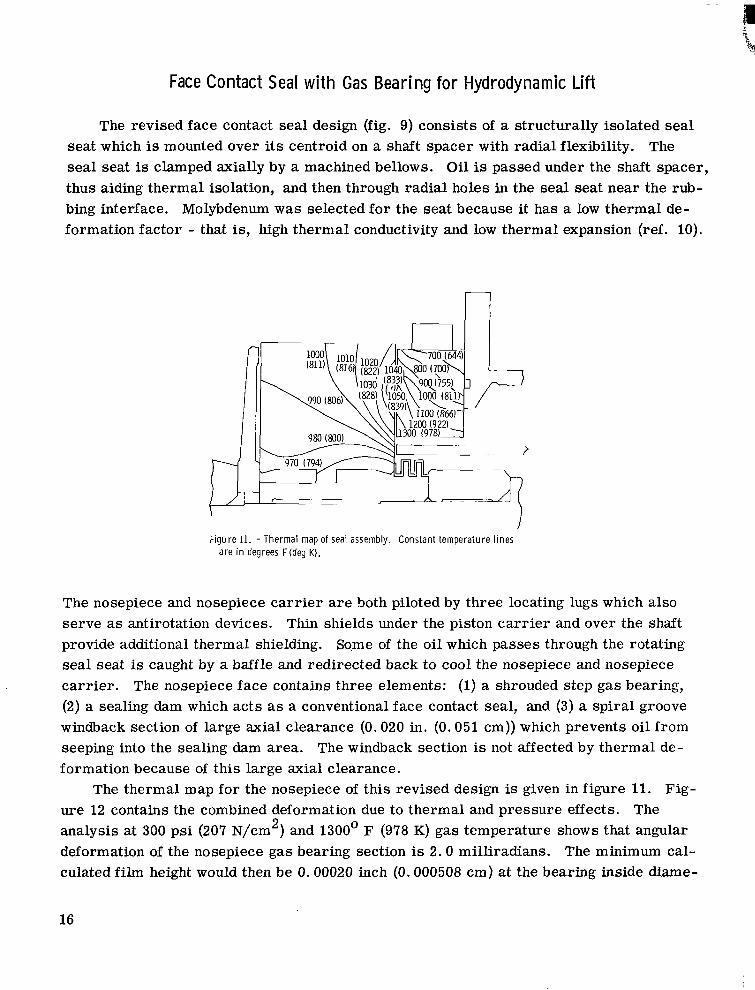
The revised face contact seal design (fig. 9) consists of a structurally isolated seal seat which is mounted over its centroid on a shaft spacer with radial flexibility. The seal seat is clamped axially by a machined bellows. Oil is passed under the shaft spacer, thus aiding thermal isolation, and then through radial holes in the seal seat near the rub- bing interface. Molybdenum was selected for the seat because it has a low thermal de- formation factor - that is, high thermal conductivity and low thermal expansion (ref. 10).
Figure 11. - Thermal map of seal assembly. Constant temperature l ines a re in degrees F(deg K).
The nosepiece and nosepiece car r ie r are both piloted by three locating lugs which also serve as antirotation devices. Thin shields under the piston car r ie r and over the shaft provide additional thermal shielding. Sqme of the oil which passes through the rotating seal seat is caught by a baffle and redirected back to cool the nosepiece and nosepiece carr ier . The nosepiece face contains three elements: (1) a shrouded step gas bearing, (2) a sealing dam which acts as a conventional face contact seal, and (3) a spiral groove windback section of large axial clearance (0.020 in. (0.051 cm)) which prevents oil from seeping into the sealing dam area. The windback section is not affected by thermal de- formation because of this large axial clearance.
The thermal map for the nosepiece of this revised design is given in figure 11. Fig- ure 12 contains the combined deformation due to thermal and pressure effects. The analysis at 300 psi (207 N/cm ) and 1300' F (978 K) gas temperature shows that angular deformation of the nosepiece gas bearing section is 2.0 milliradians. The minimum cal- culated film height would then be 0.00020 inch (0.000508 cm) at the bearing inside diame-
2
16
I -
5%' F (550 K) o i l -a i r mist at 0 psig (0 Nkm2g)
1
Nosepiece 0.0007 (0.0018)
growth
300 psig (207 Nlcmzg) O*Oo5 (0.013)
1
IT Radial
' : : I I
1 L l n i t i a l room temperature shape
L - 1
1 y , ;
L . i CD-9690 Figure 12. - Seal deformation and growth due to temperature and pressure. A l l dimensions
are in inches (cm).
(0.0025 cm) deep 0.04 in. 5.96 in. diam. (0.10 cm) ( 15.14 cm) deep \ 6.46 " in. diam.
(16.4 cm) \
8 I
6 I
4 I
2 Gap height, h, in.
1 1 25 3 0 ~ 1 0 - ~
I 20
I 15
I 10
I 5
I 0
Gap height, h, cm
Figure 13. - Calculated load capacity of gas bearing portion of seal face 20 step type pads; 300 psig (207 N/cm2 g) gas pressure; 1300O F (978 K) gas temperature; 500 fllsec (152 mlsec) s l id ing velocity; 1 mil l i radian tilt of seal faces.
17
I
111 1l1l1111l11ll1ll11l111111II
ter and 0.00050 inch (0.00127 cm) at the gas bearing outside diameter; the gas bearing can accommodate this tilt angle. Of more concern is the milliradian deformation across the sealing dam. Since this deformation has a divergent tendency, the opening force is expected to decrease with increasing deformation; however, the analysis shows that the gas bearing will accept the force changes and prevent seal face contact. Figure 13 shows the calculated gas bearing load capacity.
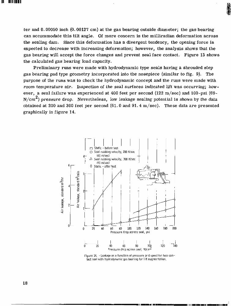
Preliminary runs were made with hydrodynamic type seals having a shrouded step gas bearing pad type geometry incorporated into the nosepiece (similar to fig. 9). The purpose of the runs was to check the hydrodynamic concept and the runs were made with room temperature air. Inspection of the seal surfaces indicated lift was occurring; how- ever, a seal failure was experienced at 400 feet per second (122 m/sec) and 100-psi (69- N/cm ) pressure drop. Nevertheless, low leakage sealing potential is shown by the data obtained at 200 and 300 feet per second (61.0 and 91.4 m/sec). These data a r e presented graphically in figure 14.
2
L S
M' E
a,- (31 cu Y m a, - L .- Q
0 Static - before test 0 Seal rubbing velocity, 200 ftlsec
(61 mlsec) a Seal rubbing velocity, 300 ftlsec
(91 mlsecl 0 Static - after test
3ki I
0 20 40 60 80 100 120 140 160 180 XlO Pressure drop across seal, psi
I I I I 1 - _ I 80 100 120 140 0 20 40 60
- Pressure drop across seal, N l c d
Figure 14. - Leakage as a funct ion of pressure a n d speed for face con- tact seal wi th hydrodynamic gas bearing for l i f t augmentation.
18
Face Contact Seal wi th Lubricated Spiral Groove for Hydrodynamic Lift
A second design for providing hydrodynamic lift is shown schematically in figure 10. The overall design is structurally similar to the previous seal except that the gas bearing pads have been eliminated and seal cooling oil is made to pass through a spiral groove section which provides hydrodynamic lift (see ref. 11 for spiral groove seal theory). In operation, the spiral groove section provides the lift to establish a sealing gap of about 0.0005 inch (0.00127 cm). This lift prevents wear, limits the gas leakage to acceptable levels, and mitigates the effects of thermal angular deformation. Preliminary runs with seals employing this spiral lift concept showed operation at less than 0.0005-inch
3 (0.00127-cm) film thickness and 0.5 standard cubic foot per minute (0.9 m /hr) leakage at 100 feet per second (30. 5 m/sec) sliding velocity at 75 psi (52 N/cm2). Typical leak- age data is given in figure 15.
c .- E .
% E m v c co YI - a,- m m x m a,
L - .- Q
0
L 0
40 80 Pressure, psi -
20 40 60 Pressure, N/cm2
120
F igure 15. - A i r leakage for face seal w i th lubricated spiral groove providing hydrodynamic l ift.
19
CONCLUDING REMAR KS
Nitrogen gas inerted lubrication system studies were made using a simulated engine sump operating at 14 000 rpm with a 125-millimeter ball bearing under a 3280-pound (14 590-N) thrust load (197 000 psi (136 000 N/cm2) maximum Hertz stress) and with 6.33-inch (161-mm) mean diameter face contact seals (400 ft/sec (122 m/sec)). Three- hour screening runs with the inerted system were used to explore feasibility and establish problem areas with 500' F (533 K) nominal bulk fluid temperature and up to 750' F (672 K) bearing temperatures. Seal concept studies were also made with open lubrication systems. Face contact and hydrostatic seal performance was determined at various speeds, pressures, and temperatures. Design revisions were made to seals in order to mitigate problem s encountered.
The experimental data and analysis revealed the following: 1. Formulated dibasic acid ester (MIL-L-7808E) did not provide adequate bearing
lubrication at 600' F (589 K) outer race temperature in the inerted system. Three lubri- cants, an improved ester (twice the viscosity of dibasic acid ester) , a synthetic paraffinic fluid, and a perfluorinated polymeric fluid, were evaluated to a 700' F (644 K) bearing outer race temperature; in each case the bearings showed no deterioration in the short duration runs. However, with the perfluorinated polymeric fluid there w a s slight evi- dence of corrosion on the bearing after running at higher temperature (700' F (644 K)). A modified polyphenyl ether (C-ether) performed satisfactorily at 600' F (589 K) outer race temperature both with and without inerting.
2. The inerted system operated satisfactorily since low oxygen content (<O. 5 per- cent) was maintained during operation. Seal leakage was frequently so high, however, that a flight system of these components would be impractical. This high leakage and wear was attributed to thermal deformation of the sealing face. The role of deformation in seal performance is more clearly delineated in these full-scale hardware experiments than in more common small component studies.
3. Supporting but open lubrication system studies on two seal types (face contact and hydrostatic) also confirmed that seal face thermal deformation was a major problem. Changes in force balance, which accompany thermal deformation, can lead to severe rubbing and wear.
other an oil lubricated spiral groove for lift, showed low leakage in preliminary dynamic testing.
4. Two face seal concepts, one using a hydrodynamic gas bearing for lift and the
Lewis Research Center, National Aeronautics and Space Administration,
Cleveland, Ohio, May 17, 1968, 126-15-02-16-22.
20
REFERENCES
1. Bisson, Edmond E. ; and Anderson, William J. : Advanced Bearing Technology. NASA SP-38, 1964.
2. Reynolds, H. W. , Jr. : Turbine Oil and Test Method Development Needed for Cur- rent and Future Engines. Presented at the USAF-Southwest Research Institute Turbine Engine Lubrication Conference, Sept. 13-15, 1966.
3. Schlosser, A. L. : Powder Lubrication of Rolling Contact Bearings at Very High Speeds and Temperatures. Presented at the USAF Aerospace Fluids and Lubri- cants Conference, San Antonio, Texas, Apr. 1963.
4. Sliney, Harold E. : Bearings Run at 1250' F with Solid Lubricant. Space/Aeronautics, vol. 35, no. 3, Mar. 1961, pp. 91-100.
5. Strom, Thomas N. ; Allen, Gordon P. ; and Johnson, Robert L. : Wear and Friction of Impregnated Mechanical Carbons at Temperatures to 1400' F (760' C) in Air or Nitrogen. NASA TN D-3958, 1967.
6. Parks, A. J. ; McKibben, R. H. ; and Ng, C. C. W. : Development of Main Shaft Seals for Advanced Air Breathing Propulsion Systems. Rep. PWA-3161, Pratt & Whitney Aircraft (NASA CR-72338), Aug. 14, 1967.
7. Hingley, C. G.; Southerling, H. E. ; and Sibley, L. B. : Supersonic Transport Lubrication System Investigation. Rep. AL65T038, SKF Industries (NASA CR- 54311), May 20, 1965.
8. Hingley, C. G.; and Sibley, L. B.: Supersonic Transport Lubrication System In- vestigation. Rep. AL65T077, SKF Industries (NASA CR-54312), Nov. 20, 1965.
9. Rhoads, W. L. ; and Sibley, L. B. : Supersonic Transport Lubrication System In- vestigation. Rep. AL66T032, SKF Industries (NASA CR-54313), May 20, 1966.
Robert L. : Improving Performance of Face Contact Seals in Liquid Sodium (400' to 1000° F) by Incorporation of the Spiral-Groove Geometry. NASA T N D-3942, 1967.
10. Ludwig, Lawrence P. ; Strom, Thomas N. ; Allen, Gordon P. ; and Johnson,
11. Strom, T. N . ; Ludwig, L. P.; Allen, G. P.; and Johnson, R. L.: Spiral Groove Face Seal Concepts - Comparison to Conventional Face Contact Seals in Sealing Liquid Sodium (400' to 1000° F). Paper No. 67 WA/Lub - 17, ASME, Nov. 1967.