Performance and scalability of Fourier domain opticalcoherence tomography acceleration using
graphics processing units
Jian Li,* Pavel Bloch, Jing Xu, Marinko V. Sarunic, and Lesley ShannonSchool of Engineering Sciences, Simon Fraser University, V5A 1S6 Burnaby BC, Canada
Fourier domain optical coherence tomography (FD-OCT) is a well-established optical interferometricimaging modality that has been rapidly gainingpopularity for providing high-resolution, cross-sectional imaging in biological tissues and materials.FD-OCT is commonly used in ophthalmic imaging byclinicians and researchers to gain accurate insightinto the eyes of patients and research specimens.During FD-OCT data acquisition, a line scanningcamera of the FD-OCT system is used to collect adata set in the form of multiple scanning lines, calledamplitude scans (A-scans). A typical volumetric dataset acquired with currently available commercialsystems takes several seconds, while acquisition of
more densely sampled volumes for high-resolutionresearch applications takes even longer.
The resulting motion artefacts, which are inevita-ble for live subject imaging, can significantly affectthe volumetric image quality and diagnostic utility.In order to achieve minimal motion artefacts, higheracquisition speed is essential. The current fastestline scan camera available for spectrometer-basedFD-OCT can achieve a line rate of 200kHz with re-solution of 4096 pixels [1], and the future trend foracquisition speed is even faster [2]. However, due tothe computationally intensive nature of the FD-OCTalgorithm, real-time FD-OCT data processing anddisplaying is now facing a challenge to keep up withthe increasing data acquisition speeds of newer cam-eras. The advances in wavelength swept source OCT(SS-OCT) and parallel FD-OCT systems [3] placeeven higher demands on computation resources forreal-time data processing and display of medicalimages.
Pure software solutions for FD-OCT processing,even on the most up-to-date Intel i7 processors, de-liver processing and display rates in the tens of kilo-hertz. The massively parallel processing cores in agraphic processing unit (GPU) can be utilized to ac-celerate FD-OCT by offloading the computationallyintensive processing tasks from the CPU. Previouswork [4] reported the use of an NVIDIA GTX285as an accelerator for FD-OCT using a k-linear spec-trometer, a configuration that is not commonly usedin commercial FD-OCT systems. A followup studypresented GPU acceleration for a standard config-uration spectrometer using a high end NVIDIAFX5800 GPU [5]. The authors reported processingrates for a common-path interferometer topology, ex-cluding the additional processing steps required tocompensate for the dispersion present in the morecommon dual-arm interferometer configurationsused in ophthalmic imaging [2]. GPUs are also usedas accelerators in Monte Carlo simulations [6,7]; arecent study [8] demonstrated a speedup of approxi-mately 600× over an Intel i7 CPU for Monte Carlosimulation on the new Fermi GPU with a novelscheme to optimize memory utilization.
In this paper, we investigate the limitations ofGPU-based accelerators for real-time FD-OCT pro-cessing and project how current trends in GPU archi-tecture will scale for increasing line rates.Specifically, the contributions of this paper are:
• a GPU-accelerated software implementation ofa complete FD-OCT system; we demonstrate that theGPUs are able to process at a maximum line rate of280kHz with dispersion compensation, whereas themaximum throughput for the overall system is lim-ited to 110kHz due to the overhead incurred by datatransfers.
• the GPU-accelerated FD-OCT system incorpo-rates the dispersion compensation processing [2]required for dual-arm interferometers and retinalimaging,
• an analysis of the FD-OCT algorithm’s perfor-mance profile on a GPU and the implications of cur-rent trends in GPU architecture for future line rates.
The paper is structured as follows: Section 2summarizes the related previous work; Section 3 de-scribes the data acquisition system and processingalgorithm; results are given in Section 4, and finallywe conclude the paper and discuss future work inSection 5.
2. Background
In FD-OCT processing, all A-scans are independentof one another. This characteristic of FD-OCTsuggests speedups could be achieved by exploitingparallelism in the following aspects,
• FD-OCT A-scans will benefit from single in-struction multiple data (SIMD) processing fromthe GPU as it is in the form of vectors,
• multiple A-scans can be processed in parallelbecause individual lines are independent, and
• in the case where the vector operations involveconstants, each element within an A-scan vectorcould be processed in a pipelined fashion.
Watanabe et al. demonstrated the use of anNVIDIA GTX285 GPU to accelerate FD-OCT sys-tems with a line scan CCD camera at 27:9kHz,while achieving a real-time display frame rate of27:9 frames=s (2048 FFT size, 1000 A-scans) [4,9].The calculation of Fourier transforms from wave-length space to wave number space is avoided, be-cause a k-linear spectrometer was used. A followupstudy [10] from the same group used a linear wave-length (λ) spectrometer with a zero-filling interpola-tion technique. Zhang et al. reported a standardspectrometer configuration with a common-path in-terferometer topology [5], therefore excluding thedispersion compensation step required in the morecommon dual-arm interferometer setup. This workimplemented both the λ-to-k resampling and three-dimensional (3D) real-time volumetric renderingon a FX5800 GPU; however, only the GPU processingtime was used to evaluate the system performance.Columns 2 and 3 of Table 1 list the specifications ofthe GPUs used in the previous works.
In this paper, we investigate the performance of aGPU-accelerated FD-OCT system under imagingconditions using a dual-arm interferometer topology.It should be noted that while GPU-accelerated plat-forms deliver significant speedup by parallelizing theFD-OCT algorithm, they also require additionalsteps to copy data back and forth between the host(CPU) and device (GPU) memory; when calculatingthe maximum real-time throughput rate of GPU-accelerated platforms, the time required for theseadditional memory copies needs to be included.
The system presented is based on a commercialspectrometer customized by Bioptigen Inc. As willbe discussed in Section 3.B, in addition to all the pro-cessing functions in [5], our system also included anumerical dispersion compensation function, whichis highly computationally intensive, as it uses twoFourier transforms and vector multiplication incomplex numbers. For this reason, a higher compu-tational requirement has to be met in order toachieve the goal of real-time FD-OCT processingand display. In addition to implementing the GPU
accelerator, we also quantified the actual runtime ofeach of the processing steps of the FD-OCTalgorithmso as to gain better insight into the performance-limiting aspects of the algorithm on the GPU accel-erating platform; this information can then be usedto guide future research into accelerating the proces-sing of FD-OCT for real-time applications. As demon-strated by our analysis, the data transfer ratebetween CPU and GPU is currently the limiting fac-tor to accelerating the FD-OCT algorithm.
3. Overview of FD-OCT System
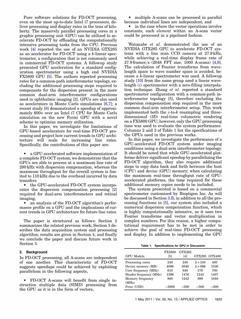
A typical FD-OCT system is composed of three stages—data acquisition, processing and display, as notedin Fig. 1.
A. Data Acquisition
During data acquisition, a line scanning cameraacquires a data set from the spectrometer, which, de-pending on the configuration of the acquisitiondevice, could be either collected to form a frame usinga frame-grabber for batch transfer or directly trans-ferred out in a serial fashion (via interfaces such asCamerLink). The demands for faster processingstems from the increasing acquisition speed, whichis in turn made possible by faster scanning rateand higher resolution. While the scanning rate ona single-channel FD-OCT acquisition on ophthalmicimaging will be bounded for safety reasons, multi-channel scanning implementations could easily scalethe equivalent speed up to six times [3].
B. FD-OCT Processing
During the processing stage, the data set is processedthrough the functions as labeled in the shaded boxes
in Fig. 1. The details of the algorithm are describedin [2,5].
1. DC Removal
This function subtracts the DC level. While the aver-age DC levels (shown as Avg. DC) will need to be ac-quired (involving add/accumulation/division) prior tothe removal, the DC level remains relatively con-stant for a specific acquisition; thus it is not neces-sary to perform DC acquisition in real time. TheDC removal function is composed of vectorsubtraction.
2. λ-to-k Resampling
Because the majority of line scanning cameras deli-ver data sets that are sampled in wavelength (λ)space, whereas the FD-OCT algorithm requires datato be presented in evenly sampled wave-number (k)space, a linear-k space data set needs to be con-structed from the one based on linear-λ space [11].Linear interpolation is used to resample the requireddata set [5]. As the sampling frequency and its range(shown as Freq.& Range in Fig. 1) for a specific imageacquisition is fixed, the coefficients for linear interpo-lation can be obtained prior to the real time FD-OCTprocessing. The λ-to-k resampling function containsvector add, multiplication, as well as reordering.
3. Dispersion Compensation
This function is an extra step to the FD-OCT proces-sing and is required for high-quality imaging inapplications such as retinal imaging [2]. The compo-nents of this function contain a Hilbert transform[2,12], which is used to construct a complex numberrepresentation of the spectral sampled data. Thecompensation is achieved by tuning the phase coeffi-cients up to the third term [2,11] (shown as PhaseCoe. in Fig. 1). The Hilbert transform is implementedby a forward fast Fourier transform (FFT), vectormultiplication in complex numbers, and an inverseFFT.
4. FFT
A cross-sectional image is produced by resolving theinformation on the delay and magnitude of the opti-cal reflection. This information can be extracted byperforming an FFT of the spectral interference sig-nal; the length of the FFT is 2048.
4. Experimental Setup
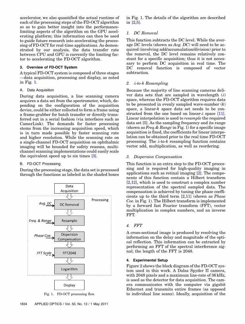
Figure 2 shows the block diagram of the FD-OCT sys-tem used in this work. A Dalsa Spyder II camera,with 2048 pixels and a maximum line-rate of 36kHz,is used as the detector for data acquisition. The cam-era communicates with the computer via gigabitEthernet and transmits entire frames (as opposedto individual line scans). Ideally, acquisition of theFig. 1. FD-OCT processing flow.
next frame is performed at the same time the currentframe is being processed.
The GPU accelerator used for our implementationwas a dual-GPU GeForce GTX295 from NVIDIA(shown in column 4 of Table 1), with 480 CUDA pro-cessor cores (240 cores per GPU) and 17892MB ofDDR3 memory (896MB per GPU), and a core clockfrequency of 576MHz. For the current implementa-tion, we are using one GPU (240 CUDA cores and896MB of GPU memory) to make a fair comparisonto previous works [4,5]. The GTX295 GPU boardcommunicates with the CPU via the 16-lane PCI-Express v2.0 bus as in the comparative works.
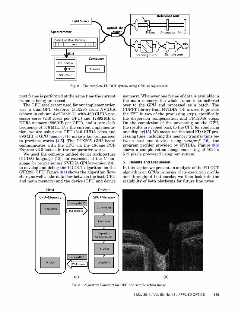
We used the compute unified device architecture(CUDA) language [13], an extension of the C lan-guage for programming NVIDIA GPUs (version 2.3),to develop and debug the FD-OCT algorithm on theGTX295 GPU. Figure 3(a) shows the algorithm flow-chart, as well as the data flow between the host (CPUand main memory) and the device (GPU and device
memory). Whenever one frame of data is available inthe main memory, the whole frame is transferredover to the GPU and processed as a batch. TheCUFFT library from NVIDIA [14] is used to processthe FFT in two of the processing steps, specificallythe dispersion compensation and FFT2048 steps.On the completion of the processing on the GPU,the results are copied back to the CPU for renderingand display[15]. We measured the total FD-OCT pro-cessing time, including the memory transfer time be-tween host and device, using cudaprof [16], theprogram profiler provided by NVIDIA. Figure 3(b)shows a sample retina image consisting of 1024 ×512 pixels processed using our system.
5. Results and Discussion
In this section we present an analysis of the FD-OCTalgorithm on GPUs in terms of its execution profileand throughput bottlenecks; we then look into thescalability of both platforms for future line rates.
Fig. 2. The complete FD-OCT system using GPU as coprocessor.
Fig. 3. Algorithm flowchart for GPU and sample retina image.
Figure 4 illustrates the percentage of the FD-OCTalgorithm’s runtime as attributed to its variouscomponent functions (similar results were seen in[9] which did not include dispersion compensation).Although the specific results presented here arefor processing multiple A-scans in a batch, the per-centages of time allocated to the various functions re-main relatively constant as long as the size of thedata set is large enough to amortize the cost of thedata transfer[17]. Figure 4 shows that the processingsteps for the FD-OCT algorithm (DC-Removal,Resample, Dispersion Compensation, FFT2048, andLogarithm) require approximately 40% of the totalruntime, while the memory (data) transfers (host-to-device and device-to-host) require approximately60%. The maximum processing line rate, excludingthe dispersion compensation and data transfer,was ∼680kHz. Adding in the time required to per-form the computationally heavy dispersion compen-sation slowed the performance down to ∼280kHz.However, to properly evaluate the real-time perfor-mance of a GPU-accelerated implementation, thedata transfer time must also be included, as it isan unavoidable overhead for existing GPU architec-tures. When the time for data transfers between theCPU and GPU is included, the resulting maximumcamera line rate for the complete system implemen-tation is ∼110kHz.
Figure 5 shows the performance of the GPU-accel-erated implementation in terms of processed A-scanlines per second versus varied batch sizes for thethree different scenarios indicated in the legend:1) Memcpy Excl, the line rate for pure processingwithout the memory copies; 2) Memcpy Incl, the linerate including both memory copies (via a 16-lane PCIExpress Bus); and 3) Intg. GPU, the extrapolated linerate for processing plus memory transfers if the sameGPU architecture had an integrated configuration.
Although NVIDIA recommends maximizing thesize of the data transfers to minimize the overhead,Fig. 5 illustrates that there is little difference in the
system’s actual maximum line rate (Memcpy Incl) forvaried batch sizes due to the fact that the majority ofthe “processing” time (∼60%) is spent in memory co-pies. The trend line excluding the memory transfers(Memcpy Excl) demonstrates that when only pureGPU processing time is considered, there is greatervariation in line rates over varied batch sizes; thetrend line plateaus around 2048 A-scans but the op-timal performance was observed at 8192 A-scan linesdue to sustained transfer rates of larger amounts ofdata. Finally, while the GPU used in these experi-ments is only available as a discrete unit due to theprocessing power requirements, we projected whatthe maximum line rates would be if it were availableas an integrated device [18]. We measured the timeneeded for data transfers between a CPU and an in-tegrated NVIDIAGeForce 9400MGPU, which sharesthe same discrete memory model where the CPUdata must be transferred to the “device memory”of the GPU (even when the host and device memoryare on the same physical device). We used this infor-mation to extrapolate what the effective line ratewould be for our GPU in this configuration (Intg.GPU). Surprisingly, it is the memory copy itself,and not the data transfer via the PCI Express bus,that accounts for themajority of the performance lossof relative to the pure GPU processing time (MemcpyExcl). In fact, the integrated GPU scenario only im-proves the effective line rate of our actual systemby 22%.
Therefore, to significantly increase the maximumline rate, the underlying memory architecture of theGPU needs to be changed to limit the number ofmemory transfers between the CPU and GPU. GPUson high-end workstations with higher PCI Expressbus frequency will provide better processing ratesfor FD-OCT, but it is still necessary for data to betransferred from the CPU for processing. However,changes to the GPU memory architecture would al-low processed data to be directly rendered to the dis-play and would significantly impact the maximumline rate of the system (nominally a 1:3× increase).We are currently investigating the latest Fermiarchitecture GTX480 GPU (shown in column 5 ofTable 1) from NVIDIA that supports duplex dataFig. 4. Percentage of GPU functions’ runtime.
Fig. 5. (Color online) Performance against A-scan batch sizes.
transfers between the host and device with the goalof reducing the impact of the memory copy by writingpostprocessed lines back to the CPU while new datafor processing is read onto the GPU. Furthermore, weare pursuing the use of multiple host threads to ex-ploit the additional spatial parallelism available onmulti-GPU devices so that one device renders anddisplays the results while the other device processesnew scans. In general, the key to improving thethroughput rates for real-time processing of in-creased line rates will be reliant on leveraging in-creased spatial parallelism in the algorithm. Asline rates increase, assuming no dramatic changes inGPU architectures, this may require the use of hard-ware acceleration to achieve this increased spatialparallelism.
In summary, whereas the GPU processing has aline rate of ∼280kHz, the system’s effective line rateis ∼110kHz. To compare our implementation to pre-vious work, we exclude the data transfer time as wellas the dispersion compensation function, resulting ina maximum line rate of ∼680kHz. By comparison,the implementation of [5] has a reported maximumline rate of ∼320kHz on the FX5800 GPU, demon-strating that our implementation achieves faster linerate on a GPU with the same number of processingcores but less memory and a slower clock rate.
B. Scalability of Using GPUs as FD-OCT Accelerators
While technology sizes continue to decrease drama-tically, following the trends predicted by Moore’s law[19], clock speeds have leveled off due to power con-sumption and heat dissipation requirements. Thus,improved computing power is provided in terms ofspatial processing, or additional processing units.This additional processing power is extremely bene-ficial to data processing applications with indepen-dent data sets that can be processed in parallel, asin the case of FD-OCT, where each A-scan can be pro-cessed independently. Ideally, as the number of pro-cessing cores increases, larger batch sizes can beprocessed in parallel to increase the throughput.
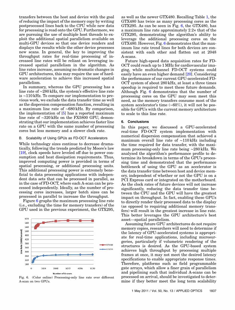
Figure 6 graphs the maximum processing line rate(i.e., excluding the time for memory transfers) of theGPU used in the previous experiment, the GTX295,
as well as the newer GTX480. Recalling Table 1, theGTX480 has twice as many processing cores as theGTX295. As can be seen in Fig. 6, the GTX480, hasa maximum line rate approximately 2:2× that of theGTX295, demonstrating the algorithm’s ability toleverage the additional processing cores on theGTX480. However, Fig. 6 demonstrates that themax-imum line rate trend lines for both devices are con-sistent with each other and flatten out at 2048A-scans.
Future high-speed data acquisition rates for FD-OCT could reach up to 1MHz for cardiovascular ima-ging, while multichannel FD-OCT systems couldeasily have an even higher demand [20]. Consideringthe performance of our current GPU-accelerated FD-OCT system of about 280kHz, at least a three timesspeedup is required to meet these future demands.Although Fig. 6 demonstrates that the number ofprocessing cores on the GPU may soon meet thisneed, as the memory transfers consume most of thesystem accelerator’s time (∼60%), it will not be pos-sible for GPUs with the current memory architectureto scale to this line rate.
6. Conclusions
In this paper, we discussed a GPU-acceleratedreal-time FD-OCT system implementation withnumerical dispersion compensation that achieved amaximum overall line rate of ∼110kHz includingthe time required for data transfer, with the maxi-mum processing-only line rate being ∼280kHz. Weanalyzed the algorithm’s performance profile to de-termine its breakdown in terms of the GPU’s proces-sing time and demonstrated that the performancebottleneck of using the GPU as an accelerator isthe data transfer time between host and device mem-ory, independent of whether or not the GPU is on aPCI Express card or integrated on the motherboard.As the clock rates of future devices will not increasesignificantly, reducing the data transfer time be-tween the CPU and the GPU will have the greatestimpact on throughput. In fact, enabling these GPUsto directly render their processed data to the display(as opposed to requiring additional memory trans-fers) will result in the greatest increase in line rate.This better leverages the GPU architecture’s bestasset—spatial parallelism.
Assuming future GPU architectures do not requirememory copies, researchers will need to determine ifthe latency of GPU-accelerated systems is appropri-ate for real-time applications, including microsur-geries, particularly if volumetric rendering of thestructures is desired. As the GPU-based systemachieves high throughput by processing multipleframes at once, it may not meet the desired latencyspecifications to enable appropriate response times.Therefore, platforms such as field programmablegate arrays, which allow a finer grain of parallelismand pipelining such that individual A-scans can beprocessed on arrival, should be investigated to deter-mine if they better meet the long term scalability
Fig. 6. (Color online) Processing-only line rate over differentA-scan on two GPUs.
requirements of future data acquisition rates andreal-time response times.
We would like to thank the Canadian NationalScience and Engineering Research Council (NSERC),the Canadian Institute of Health Research (CIHR),and the Michael Smith Foundation for Health Re-search (MSFHR) for funding this project. We wouldalso like to thank the Canadian MicroelectronicsCorporation (CMC) for their equipment donations.
References and Notes1. T. Schmoll, C. Kolbitsch, and R. A. Leitgeb, “Ultra-high-speed
volumetric tomography of human retinal blood flow,” Opt.Express 17, 4166–4176 (2009).
2. M.Wojtkowski,V. Srinivasan, T.Ko, J. Fujimoto,A.Kowalczyk,and J. Duker, “Ultrahigh-resolution, high-speed, Fourier do-main optical coherence tomography and methods for disper-sion compensation,” Opt. Express 12, 2404–2422 (2004).
3. M. K. K. Leung, A. Mariampillai, B. A. Standish, K. K. C. Lee,N. R. Munce, I. A. Vitkin, and V. X. D. Yang, “High-powerwavelength-swept laser in littman telescope-less polygon fil-ter and dual-amplifier configuration for multichannel opticalcoherence tomography,” Opt. Lett. 34, 2814–2816 (2009).
4. Y. Watanabe and T. Itagaki, “Real-time display on Fourier do-main optical coherence tomography system using a graphicsprocessing unit,” J. Biomed. Opt. 14, 060506 (2009).
5. K. Zhang and J. U. Kang, “Real-time 4D signal processing andvisualization using graphics processing unit on a regularnonlinear-k Fourier-domain OCT system,” Opt. Express 18,11772–11784 (2010).
6. Q. Fang and D. A. Boas, “Monte Carlo simulation of photonmigration in 3D turbid media accelerated by graphics proces-sing units,” Opt. Express 17, 20178–20190 (2009).
7. N. Ren, J. Liang, X. Qu, J. Li, B. Lu, and J. Tian, “GPU-basedMonte Carlo simulation for light propagation in complexheterogeneous tissues,” Opt. Express 18, 6811–6823(2010).
8. E. Alerstam, W. C. Y. Lo, T. D. Han, J. Rose, S. Andersson-Engels, and L. Lilge, “Next-generation acceleration and code
optimization for light transport in turbid media using GPUs,”Biomed. Opt. Express 1, 658–675 (2010).
9. Y. Watanabe and T. Itagaki, “Real-time display on SD-OCTusing a linear-in-wavenumber spectrometer and a graphicsprocessing unit,” Proc. SPIE 7554, 75542S (2010).
10. Y. Watanabe, S. Maeno, K. Aoshima, H. Hasegawa, and H.Koseki, “Real-time processing for full-range Fourier-domainoptical-coherence tomography with zero-filling interpolationusing multiple graphic processing units,” Appl. Opt. 49,4756–4762 (2010).
11. J. Xu, L. Molday, R. Molday, and M. Sarunic, “In vivo imagingof the mouse model of X-linked juvenile retinoschisis withFourier domain optical coherence tomography,” Invest.Ophthalmol. Visual Sci. 50, 2989 (2009).
12. J. Goodman, Statistical Optics (Wiley, 2000).13. “NVIDIA CUDA Programming Guide,” (2009), http ://
17. Because of the overhead incurred from initiating data trans-fers between device and host memory, data copies need to be“batched” (i.e., multiple individual copies grouped togetherinto a single multiword copy) to amortize this cost [13]. InFig. 4, a batch size of 8192 was used.
18. Integrated GPUs are packaged on the same chip as thesystem memory controller and system I/O controller to pro-vide a compact, low cost, low power-consumption solution.Because of these design constraints, they provide lessprocessing power and fewer processing cores to meet therequirements.
19. G. Moore, “Cramming more components onto integratedcircuits,” Proc. IEEE 86, 82–85 (1998).
20. W. Wieser, B. R. Biedermann, T. Klein, C. M. Eigenwillig, andR. Huber, “Multi-megahertz OCT: High quality 3d imaging at20 million a-scans and 4.5 gvoxels per second,” Opt. Express18, 14685–14704 (2010).