Performance Comparisons Among Radial Flux, Multi-stage Axial Flux and Three-phase Transverse
Flux PM Machines for Downhole Applications
Anyuan Chen, Robert Nilssen and Arne Nysveen
Norwegian University of Science and Technology, Trondheim, 7034, Norway
Abstract- The aim of this paper is to provide performance
comparisons among conventional radial flux (RF), multi-stage axial flux (AF) and three-phase transverse flux (AF) permanent magnet (PM) machines for downhole applications where the outer-diameters are limited by well sizes, but the axial lengths can be relatively long. The comparison procedure is based on a high ambient temperature of 150ºC, a small outer-diameter of 100mm, a current density of 4A/mm2, an electrical loading of 20kA/m and a constant speed of 1000rpm. Three machine prototypes are chosen and optimized individually in terms of maximum torque density on the basis of some common constraints. The comparisons are focused on the torque density and the efficiency of the machines with respect to different pole numbers and axial lengths. For a specific downhole application without an external cooling system, the obtained results provide an indication of machines best suited with respect to the performance and size.
I. INTRODUCTION
The current standard electrical downhole machine is the induction machine which is relatively inefficient. Permanent magnet (PM) machines, having higher efficiencies, higher torque densities and smaller volumes, have widely employed in industrial applications to replace conventional machines, but few have been developed for downhole applications due to the high ambient temperatures in deep wells and the low temperature stability of PM materials over time. Today, with the development of advanced technologies and applications of high temperature magnets, it is increasingly interesting for oil and gap industries to develop PM machines for downhole applications [1][2] where the machine outer-diameters are typically limited to 100-200 mm by well sizes, but the axial lengths can be relatively long.
This paper compares the performance of conventional radial flux (RF), multi-stage axial flux (AF) and three-phase transverse flux (TF) permanent magnet (PM) machines for downhole applications. Several papers have already presented machine performance comparisons [3]-[6], but all of them focused on RFPM and single-stage AFPM machines. The authors have found no paper including multi-stage AFPM and TFPM machines. In this paper, three machine prototypes are chosen and optimized individually in terms of maximum torque density based on some common constraints without considering the mechanical construction machine and
manufacturing problems. The comparisons are focused on the torque density and the efficiency of the machines with respect to their pole numbers and machine axial lengths based on analytical calculations.
II. THREE MACHINE PROTOTYPES
According to the traveling direction of their magnetic field in the airgap, PM machines are categorized into RFPM, AFPM and TFPM machines. Each of them has many construction variations depending on specific applications. In downhole applications, machine construction is chosen based upon following considerations: • Cylindrical shape: suitable for cylindrical wells. • Internal-rotor machines: Normally, with the same
dimensions external-rotor RFPM and TFPM machines could provide higher torque density than internal-rotor machines since the former can have greater airgap radius, but it is not the case in downhole applications where the machines need to be enclosed to protect the moving rotors from the harsh conditions within a small radial space. The internal-rotor machines can use their stator yokes to achieve this function and may have greater outer diameters by eliminating the extra shields required for the external-rotor machines. For AFPM machines an extra shield is always needed. However, this is not taken into account in the investigations presented in this paper.
• Three-phase machines: Considering the machine self-starting and standard control systems.
• Multi-stage AFPM machines: To provide good performance, a single-stage AFPM machine usually has a disc shape, so it is not practical to design a single-stage AFPM machine with a long axial length. Multi-stage AFPM machines having n+1 stators/rotor and n rotors/stator can have a long axial length by increasing the number of stages.
• Single-sided TFPM machines: Double-sided TFPM machines can usually provide higher torque by fully utilizing the magnetic flux, but they need more radial space and it is challengeable to manufacture them within a small radius. Single-sided TFPM machines are therefore chosen here. Summarizing the aspects above-mentioned, internal-rotor
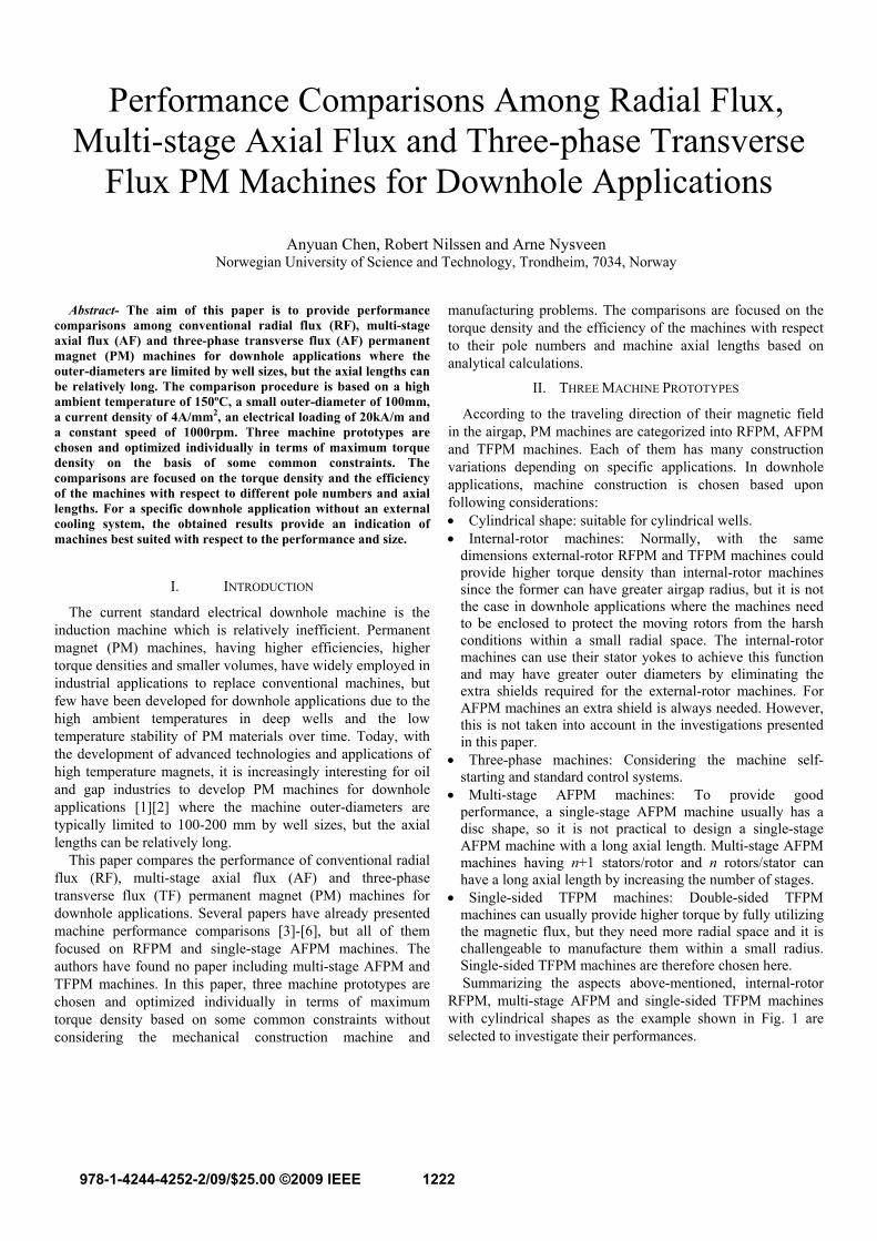
RFPM, multi-stage AFPM and single-sided TFPM machines with cylindrical shapes as the example shown in Fig. 1 are selected to investigate their performances.
Fig. 1. Example of three machine types (a) RFPM (b) Multi-stage AFPM (here 3 stages) (c) Three-phase TFPM machines.
III. MACHINE CONSTRAINTS
To fairly perform comparisons among the three type machines, some constraints have to be given as listed as follows: • The pole number is freely chosen, but the pole pitch should
not be less than 10mm to limit the inter-pole flux leakage of the machines [10] [12].
• The maximum flux density in the air gap is limited to 0.9T in order to limit the flux leakage in the TFPM machine.
• The saturation flux density in the iron parts is chosen to be 1.8T except in the tooth iron of the TFPM machine where it is assumed to be 0.9T to limit the flux leakage.
• All the iron parts are assumed to be ideal with infinite permeability.
• An application with a constant speed of 1000rpm is assumed.
• Only small current densities and electrical loadings are considered. Both the long distances from the topside to downhole and the small radial space limited by wells make it
difficult to have a forced cooling system downhole to dissipating heat. For low speed applications like this case (1000rpm), the dominant loss in the machines is the copper loss which is proportional to the square of machine current. According to [7], a current density of 4A/mm2 and an electrical loading of 20kA/m are appropriate values for an enclosed machine with no external cooling.
• Only slotted machines with surfaced-mounted PM are selected. To produce the same electromagnetic torque with the same dimensions, slotted machines usually have higher magnetic loading and less electrical loading compared with slot-less machines that generally have less magnetic loading, but higher electrical loading. In the case of downhole applications, the selected electrical loading is relatively small; therefore, slotted machines with high magnetic loading are selected. Assumed constraints for the design are listed in TABLE I.
IV. COMPARISON PROCEDURE
A. Electromagnetic Torque Calculation The electromagnetic torques developed at the machine
airgaps of the RFPM and AFPM machines can be expressed as (1) [6][8].
2 21
3 21
1 (RFPM machines)2
(1 ) (AFPM machines)
t g o
t g so
k SB D LT
k SB R
π λ
π λ λ
⎧⎪= ⎨⎪ −⎩
(1)
where Bg1 is the rms value of the fundamental airgap flux density, λ is the ratio of Di/Do, here Di and Do are respectively the machine inner- and outer-stator diameters, and for the RFPM and TFPM machines Do equals to the well diameter. L is the active length of the machine windings. kt is the machine constant that depends on both the actual airgap flux density distribution and the winding arrangement. For square-wave flux density distributions and full pitch windings, its value is unity, here it is assumed to be the case. S is the electrical loading with unit in A/m. Rso is the outer-stator radius of the AFPM machines and it is dependent of pole number p and evaluated by (2) [4] (see Fig. 4).
TABLE I
ASSUMED CONSTRAINTS FOR THE DESIGN Parameters Values Well diameter 100mm Machine axial length 0.1~1m Saturation flux density 1.8T Air gap 1.5 mm Ambient temperature 150ºC Speed 1000rpm Copper conductivity@20 ºC 1.72 10-8Ω/m Current density 4A/mm2 Electrical loading 20kA/m PM remanence @20ºC 1.2T PM temperature coefficient -0.00045K-1 Specific loss factor 2.7W/kg Winding fill factor 0.6 Temperature coefficient (Cu) 0.0039 K-1
1223
( ) ( )/ 2
; for NS type sin cos
; for NN type 2 (1 )
o
so
sat o
sat g pm
D
p pRpB D
pB B
π π
α π λ
⎧⎪
+⎪= ⎨⎪⎪ + +⎩
(2)
where αpm is the magnet coverage, here it is assumed to be unity, Bsat is the iron saturation flux density, Bg is the flux density in the air gap over the magnets, and its distribution is assumed to be a square waveform. The relationship between Bg1 and Bg is
12 2 sin( )
2g g pmB B παπ
= . (3)
The torque expression of the TFPM machines is derived as follows:
The electromagnetic torque produced by an electrical machine can be calculated by
/ mT mEI ω= . (4) where m is the phase number, E is the induced phase voltage, and for the TFPM machines it can be expressed as (5). I is the phase current and determined by (6), ωm is the mechanical angular speed and calculated by (7).
12 t e s so g mE k f n k D B lσπ λ= (5) where lm is the magnet depth in the TFPM machine (see Fig. 10) and kσ is the flux leakage factor representing the amount of flux from the airgap to the stator teeth, ns is the conductor number in one phase, fe is the electrical frequency.
/o sI D S nπ λ= (6)
4 /m ef pω π= (7) Substituting (5), (6) and (7) into (4), the torque expression for the TFPM machines is obtained as
2 21
12 t g o mT k k mp SB D lσ π λ= . (8)
B. End Winding Approximation The method presented in [4] for calculating the end-winding
length of RFPM and AFPM machines is employed here. No end-winding exits in the TFPM machines.
The equivalent length of half the end connects of a winding coil in the RFPM is approximated as
2
_ ( ) / 2end RF o tl D H pπ λ= + . (9) where Ht is the tooth height determined by magnetic design of the stator core.
Multi-stage AFPM machines may have either the same or different magnet polarity at both sides of each stator, so are
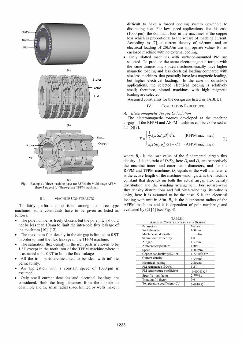
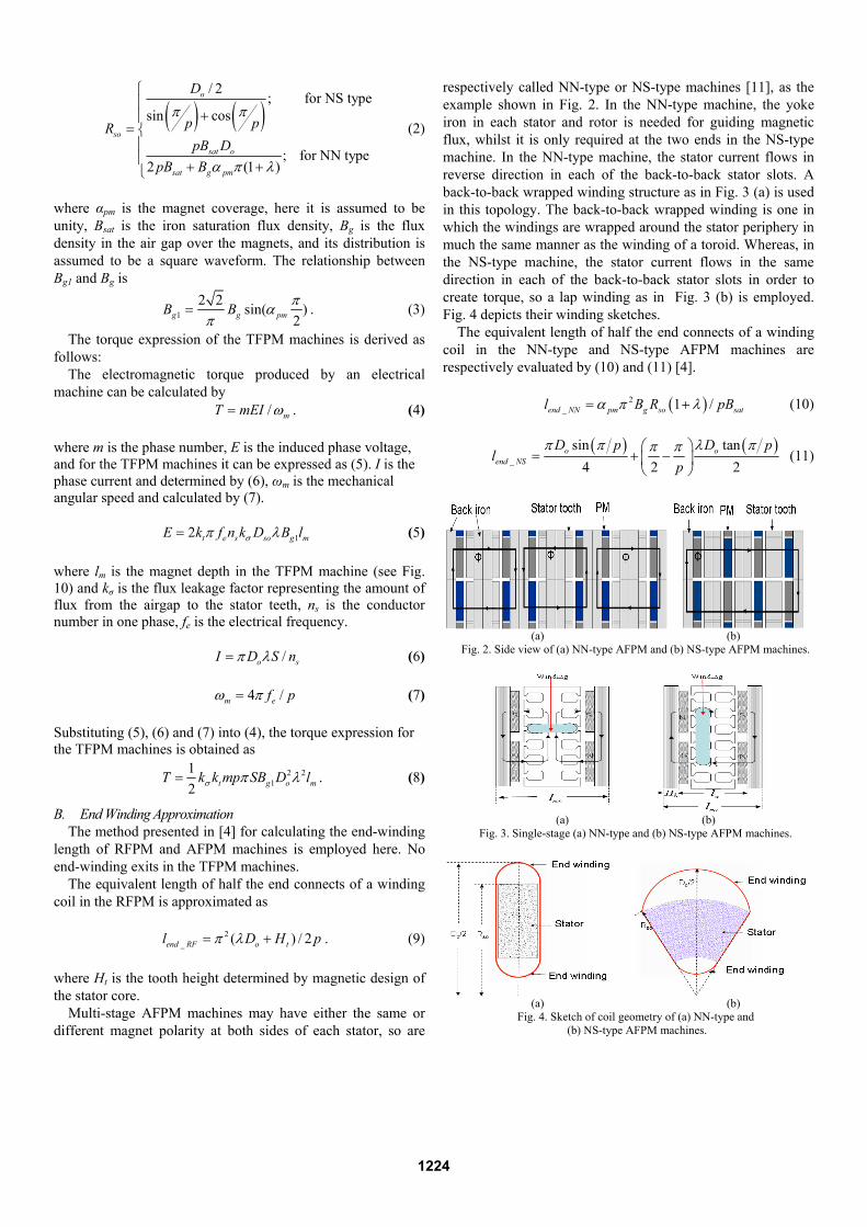
respectively called NN-type or NS-type machines [11], as the example shown in Fig. 2. In the NN-type machine, the yoke iron in each stator and rotor is needed for guiding magnetic flux, whilst it is only required at the two ends in the NS-type machine. In the NN-type machine, the stator current flows in reverse direction in each of the back-to-back stator slots. A back-to-back wrapped winding structure as in Fig. 3 (a) is used in this topology. The back-to-back wrapped winding is one in which the windings are wrapped around the stator periphery in much the same manner as the winding of a toroid. Whereas, in the NS-type machine, the stator current flows in the same direction in each of the back-to-back stator slots in order to create torque, so a lap winding as in Fig. 3 (b) is employed. Fig. 4 depicts their winding sketches.
The equivalent length of half the end connects of a winding coil in the NN-type and NS-type AFPM machines are respectively evaluated by (10) and (11) [4].
( )2
_ 1 /end NN pm g so satl B R pBα π λ= + (10)
( ) ( )_
sin tan4 2 2
o oend NS
D p D pl
pπ π λ ππ π⎛ ⎞
= + −⎜ ⎟⎝ ⎠
(11)
(a) (b)
Fig. 2. Side view of (a) NN-type AFPM and (b) NS-type AFPM machines.
(a) (b)
Fig. 3. Single-stage (a) NN-type and (b) NS-type AFPM machines.
(a) (b)
Fig. 4. Sketch of coil geometry of (a) NN-type and (b) NS-type AFPM machines.
1224
C. Torque density Calculations The torque density here is defined as the ratio of
electromagnetic torque to overall machine volume including end-windings.
2
4T
o tot
TD L
ξπ
= (12)
where Ltot is the total machine axial length.
D. Efficiency Calculations The copper loss is calculated by
2
cu f cu cuP k J A lθρ= . (13)
where Acu is the copper area. J is the current density. kf is the winding fill factor. lcu is the copper length including the end windings. ρθ is the copper resistivity at temperature θ and is calculated by
20 (1 ( 20 ))θρ ρ α θ= + − ° . (14) where α is the temperature coefficient.
The iron loss in each iron part is approximated by [9]
2 30.078 (100 ) 10Fe Fe FeP Wf f B G −= + . (15) where W is the specific loss factor in W/kg, GFe is the weight of the iron part, while BFe is the peak flux density in the corresponding iron part. The efficiency is then evaluated by
/( )m m cu FeT T P Pη ω ω= + + . (16)
V. OPTIMAL DESIGN VARIABLES
As clearly seen from (1) and (8), the key variables for each machine design are Bg (Bg1) and λ. In order to obtain the optimal machines with the highest torque density, their optimal values addressing to the maximum torque densities with respect to different pole numbers and machine axial lengths are investigated for each of the prototypes.
A. RFPM Machines For a specific RFPM machine the total machine axial length
is evaluated by
tot eaL L l= + . (17) where lea is the axial length of the end-winding encumbrance and is assumed as [4]
_2 /ea end RFl l π= . (18)
The torque density can be calculated by (1), (9), (12), (17) and (18) for a given pole number and a machine length after
magnetic design. It should be noted that, to calculate the torque from (1), S=20kA/m is used for the machines with small λ values, which have enough space for copper in their stators. For the machines with big λ values, the machine current is limited by the available copper area, and the electrical loading is then determined by
/cu f oS A Jk Dπ λ= . (19)
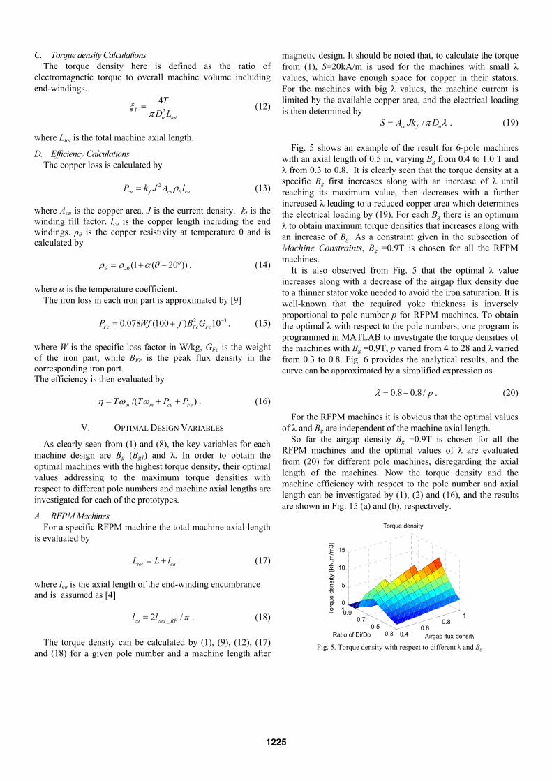
Fig. 5 shows an example of the result for 6-pole machines with an axial length of 0.5 m, varying Bg from 0.4 to 1.0 T and λ from 0.3 to 0.8. It is clearly seen that the torque density at a specific Bg first increases along with an increase of λ until reaching its maximum value, then decreases with a further increased λ leading to a reduced copper area which determines the electrical loading by (19). For each Bg there is an optimum λ to obtain maximum torque densities that increases along with an increase of Bg. As a constraint given in the subsection of Machine Constraints, Bg =0.9T is chosen for all the RFPM machines.
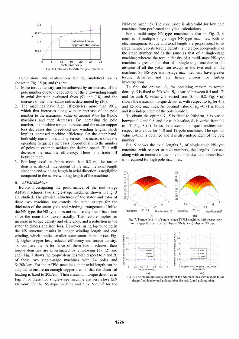
It is also observed from Fig. 5 that the optimal λ value increases along with a decrease of the airgap flux density due to a thinner stator yoke needed to avoid the iron saturation. It is well-known that the required yoke thickness is inversely proportional to pole number p for RFPM machines. To obtain the optimal λ with respect to the pole numbers, one program is programmed in MATLAB to investigate the torque densities of the machines with Bg =0.9T, p varied from 4 to 28 and λ varied from 0.3 to 0.8. Fig. 6 provides the analytical results, and the curve can be approximated by a simplified expression as
0.8 0.8 / pλ = − . (20)
For the RFPM machines it is obvious that the optimal values of λ and Bg are independent of the machine axial length.
So far the airgap density Bg =0.9T is chosen for all the RFPM machines and the optimal values of λ are evaluated from (20) for different pole machines, disregarding the axial length of the machines. Now the torque density and the machine efficiency with respect to the pole number and axial length can be investigated by (1), (2) and (16), and the results are shown in Fig. 15 (a) and (b), respectively.
0.40.6
0.81
0.30.5
0.70.910
5
10
15
Airgap flux density
Torque density
Ratio of Di/Do
Torq
ue d
ensi
ty [k
N.m
/m3]
Fig. 5. Torque density with respect to different λ and Bg.
1225
4 8 12 16 20 24 28
0.65
0.7
0.75
0.8
Pole number p
λ
calculated curveapproximated curve
Fig. 6. Optimal λ for different pole numbers.
Conclusions and explanations for the analytical results
shown in Fig. 15 (a) and (b) are: 1. More torque density can be achieved by an increase of the
pole number due to the reduction of the end-winding length in axial direction evaluated from (9) and (18), and the increase of the inner-stator radius determined by (20).
2. The machines have high efficiencies, more than 90%, which first increases along with an increase of the pole number to the maximum value of around 94% for 8-pole machines and then decreases. By increasing the pole number, the machine torque increases and the stator copper loss decreases due to reduced end winding length, which implies increased machine efficiency. On the other hand, both eddy current loss and hysteresis loss increase since the operating frequency increases proportionally to the number of poles in order to achieve the desired speed. This will decrease the machine efficiency. There is a trade off between them.
3. For long axial machines more than 0.2 m, the torque density is almost independent of the machine axial length since the end-winding length in axial direction is negligible compared to the active winding length of the machines.
B. AFPM Machines Before investigating the performance of the multi-stage
AFPM machines, two single-stage machines shown in Fig. 3 are studied. The physical structures of the stator and rotor of these two machines are exactly the same except for the thickness of the stator yoke and winding arrangement. Unlike the NN type, the NS type does not require any stator back iron since the main flux travels axially. This feature implies an increase in torque density and efficiency, and a reduction in the stator thickness and iron loss. However, using lap winding in the NS structure results in longer winding length and end winding, which implies smaller outer stator diameter (see Fig. 4), higher copper loss, reduced efficiency and torque density. To compare the performance of these two machines, their torque densities are investigated by employing (1), (2) and (12). Fig. 7 shows the torque densities with respect to λ and Bg of these two single-stage machines with 24 poles and S=20kA/m. For the AFPM machines, their axial length can be adapted to ensure an enough copper area so that the electrical loading is fixed to 20kA/m. Their maximum torque densities in Fig. 7 for these two single-stage machine are very close (5.9 kN.m/m3 for the NS-type machine and 5.8k N.m/m3 for the
NN-type machine). The conclusion is also valid for low pole machines from performed analytical calculations.
For a multi-stage NN-type machine as that in Fig. 2, it consists of multiple single-stage NN-type machines, both its electromagnetic torque and axial length are proportional to its stage number, so its torque density is therefore independent of the stage number and is the same as that of a single-stage machine; whereas the torque density of a multi-stage NS-type machine is greater than that of a single-stage one due to the absence of all the yoke iron except at the two ends of the machine. So NS-type multi-stage machines may have greater torque densities and are hence chosen for further investigations.
To find the optimal Bg for obtaining maximum torque density, S is fixed to 20kA/m, Bg is varied between 0.4 and 1T, and for each Bg value, λ is varied from 0.4 to 0.8. Fig. 8 (a) shows the maximum torque densities with respect to Bg for 4, 8 and 12-pole machines. An optimal value of Bg =0.7T is found and it is independent of the pole number.
To obtain the optimal λ, S is fixed to 20kA/m, λ is varied between 0.4 and 0.8, and for each λ value, Bg is varied from 0.4 to 1T. Fig. 8 (b) shows the maximum torque densities with respect to λ value for 4, 8 and 12-pole machines. The optimal value λ=0.55 is obtained and it is also independent of the pole number.
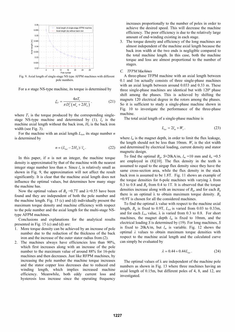
Fig. 9 shows the axial lengths lns of single-stage NS-type machines with respect to pole numbers, the lengths decrease along with an increase of the pole number due to a thinner back iron required for high pole machines.
0.40.6
0.81
0.4
0.6
0.82
3
4
5
6
Airgap flux density [T]Ratio of Di/Do
Torq
ue d
esity
[kN
.m/m
3]
0.4
0.60.8
1
0.4
0.6
0.83
4
5
6
Airgap flux density [T]Ratio of Di/Do
Torq
ue d
esity
[kN
.m/m
3]
(a) (b)
Fig. 7. Torque density of single –stage TFPM machines with respect to λ and airgap flux density (a) 24-pole NN type (b) 24-pole NS type.
0.4 0.5 0.6 0.7 0.8 0.9 11
1.5
2
2.5
3
3.5
4
Airgap flux density [T]
Max
imum
torq
ue d
ensi
ty [k
N.m
/m3]
4 poles8 poles12 poles
0.3 0.35 0.4 0.45 0.5 0.55 0.6 0.650.7 0.751
1.5
2
2.5
3
3.5
4
Ratio of Di/Do
Max
imum
torq
ue d
ensi
ty [k
N.m
/m3]
4 poles8 poles12 poles
(a) (b)
Fig. 8. The maximum torque density of the NS machines with respect to (a) airgap flux density and pole number (b) ratio λ and pole number.
1226
4 8 12 16 20 24 280.02
0.025
0.03
0.035
0.04
0.045
0.05
0.055
0.06
Pole number
Axi
al le
ngth
[m]
Axial length of single-stage AFPM machineAxial length (la) without back iron
Fig. 9. Axial length of single-stage NS type AFPM machines with different
pole numbers. For a n stage NS-type machine, its torque is determined by
( )1
2
42T
o a b
nTD nl H
ξπ
=+
. (21)
where T1 is the torque produced by the corresponding single-stage NS-type machine and determined by (1), la is the machine axial length without the back iron, Hb is the back iron width (see Fig. 3).
For the machine with an axial length Ltot, its stage number n is determined by
( 2 ) /tot b an L H l= − . (22)
In this paper, if n is not an integer, the machine torque density is approximated by that of the machine with the nearest integer stage number less than n. Since la is relatively small as shown in Fig. 9, the approximation will not affect the result significantly. It is clear that the machine axial length does not influence the optimal values, but determines how many stage the machine has.
Now the optimal values of Bg =0.7T and λ=0.55 have been found and they are independent of both the pole number and the machine length. Fig. 15 (c) and (d) individually present the maximum torque density and machine efficiency with respect to the pole number and the axial length for the multi-stage NS-type AFPM machines.
Conclusions and explanations for the analytical results presented in Fig. 15 (c) and (d) are: 1. More torque density can be achieved by an increase of pole
number due to the reduction of the thickness of the back iron and the increase of the outer stator radius from (2).
2. The machines always have efficiencies less than 90%, which first increases along with an increase of the pole number to the maximum value of around 88% for 16-pole machines and then decreases. Just like RFPM machines, by increasing the pole number the machine torque increases and the stator copper loss decreases due to reduced end winding length, which implies increased machine efficiency. Meanwhile, both eddy current loss and hysteresis loss increase since the operating frequency
increases proportionally to the number of poles in order to achieve the desired speed. This will decrease the machine efficiency. The poor efficiency is due to the relatively large amount of end-winding existing in each stage.
3. The torque density and efficiency of the long machines are almost independent of the machine axial length because the back iron width at the two ends is negligible compared to the total machine length. In this case, both the machine torque and loss are almost proportional to the number of stages.
C. TFPM Machines A three-phase TFPM machine with an axial length between
0.1 and 1m actually consists of three single-phase machines with an axial length between around 0.033 and 0.33 m. These three single-phase machines are identical but with 120º phase shift among the phases. This is achieved by shifting the magnets 120 electrical degree in the rotors among the phases. So it is sufficient to study a single-phase machine shown in Fig. 10 to investigate the performance of the three-phase machine.
The total axial length of a single-phase machine is
2tot m sL l W= + . (23) where lm is the magnet depth, in order to limit the flux leakage, the length should not be less than 10mm. Ws is the slot width and determined by electrical loading, current density and stator magnetic design.
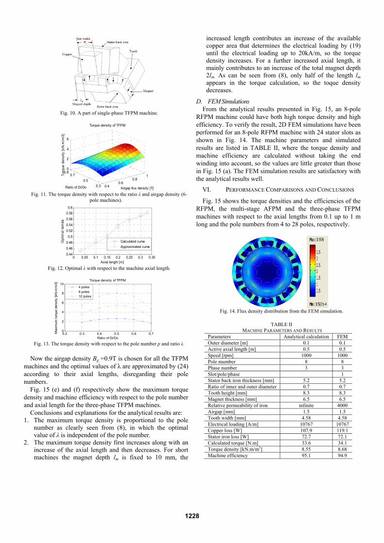
To find the optimal Bg, S=20kA/m, lm =10 mm and kσ =0.5 are employed in (8)[10]. The flux density in the teeth is assumed to equal to the airgap flux density since they have the same cross-section area, while the flux density in the stack back iron is assumed to be 1.8T. Fig. 11 shows an example of the torque densities for 6-pole machines with varying λ from 0.3 to 0.8 and Bg from 0.4 to 1T. It is observed that the torque densities increase along with an increase of Bg, and for each Bg there is an optimal λ to obtain maximum torque density. Bg =0.9T is chosen for all the considered machines.
To find the optimal λ value with respect to the machine axial length, Bg is fixed to 0.9T, Ltot is varied from 0.03 to 0.33m, and for each Ltot value, λ is varied from 0.3 to 0.8. For short machines, the magnet depth lm is fixed to 10mm, and the electrical loading S is determined by (19). For long machines, S is fixed to 20kA/m, but lm is variable. Fig. 12 shows the optimal λ values to obtain maximum torque densities with respect to the machine axial length and the calculated curve can simply be evaluated by
0.44 0.44 totLλ = + . (24)
The optimal values of λ are independent of the machine pole
numbers as shown in Fig. 13 where three machines having an axial length of 0.15m, but different poles of 4, 8, and 12, are investigated.
1227
Fig. 10. A part of single-phase TFPM machine.
0.40.6
0.81
0.30.5
0.70.8
0
2
4
6
Airgap flux density [T]
Torque density of TFPM
Ratio of Di/Do
Torq
ue d
ensi
ty [k
N.m
/m3]
Fig. 11. The torque density with respect to the ratio λ and airgap density (6-
pole machines).
0 0.05 0.1 0.15 0.2 0.25 0.3 0.35
0.440.460.480.5
0.520.540.560.580.6
Axial length [m]
Opt
imal
lam
da
Calculated curveApproximated curve
Fig. 12. Optimal λ with respect to the machine axial length.
0.2 0.3 0.4 0.5 0.6 0.70
2
4
6
8
10Torque density of TFPM
Ratio of Di/Do
Max
imum
torq
ue d
ensi
ty [k
N.m
/m3]
4 poles8 poles12 poles
Fig. 13. The torque density with respect to the pole number p and ratio λ.
Now the airgap density Bg =0.9T is chosen for all the TFPM
machines and the optimal values of λ are approximated by (24) according to their axial lengths, disregarding their pole numbers.
Fig. 15 (e) and (f) respectively show the maximum torque density and machine efficiency with respect to the pole number and axial length for the three-phase TFPM machines.
Conclusions and explanations for the analytical results are: 1. The maximum torque density is proportional to the pole
number as clearly seen from (8), in which the optimal value of λ is independent of the pole number.
2. The maximum torque density first increases along with an increase of the axial length and then decreases. For short machines the magnet depth lm is fixed to 10 mm, the
increased length contributes an increase of the available copper area that determines the electrical loading by (19) until the electrical loading up to 20kA/m, so the torque density increases. For a further increased axial length, it mainly contributes to an increase of the total magnet depth 2lm. As can be seen from (8), only half of the length lm appears in the torque calculation, so the toque density decreases.
D. FEM Simulations From the analytical results presented in Fig. 15, an 8-pole
RFPM machine could have both high torque density and high efficiency. To verify the result, 2D FEM simulations have been performed for an 8-pole RFPM machine with 24 stator slots as shown in Fig. 14. The machine parameters and simulated results are listed in TABLE II, where the torque density and machine efficiency are calculated without taking the end winding into account, so the values are little greater than those in Fig. 15 (a). The FEM simulation results are satisfactory with the analytical results well.
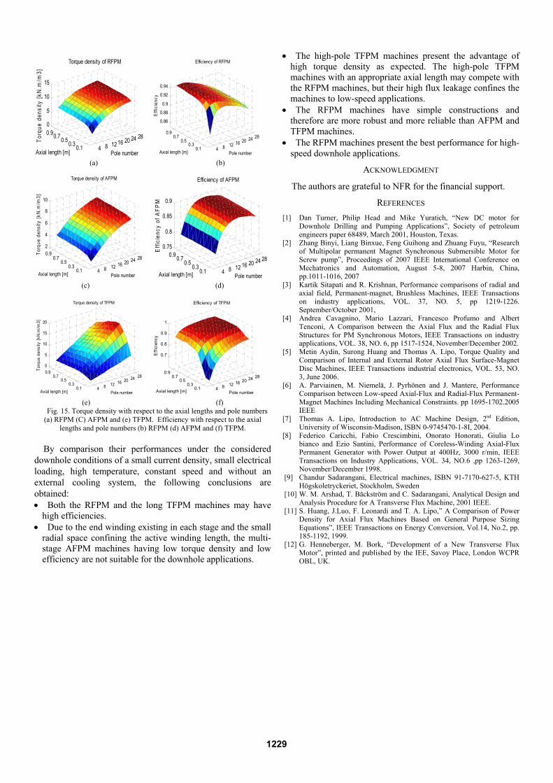
VI. PERFORMANCE COMPARISONS AND CONCLUSIONS
Fig. 15 shows the torque densities and the efficiencies of the RFPM, the multi-stage AFPM and the three-phase TFPM machines with respect to the axial lengths from 0.1 up to 1 m long and the pole numbers from 4 to 28 poles, respectively.
Fig. 14. Flux density distribution from the FEM simulation.
TABLE II
MACHINE PARAMETERS AND RESULTS Parameters Analytical calculation FEM Outer diameter [m] 0.1 0.1 Active axial length [m] 0.5 0.5 Speed [rpm] 1000 1000 Pole mumber 8 8 Phase number 3 3 Slot/pole/phase 1 Stator back iron thickness [mm] 5.2 5.2 Ratio of inner and outer diameter 0.7 0.7 Tooth height [mm] 8.3 8.3 Magnet thickness [mm] 6.5 6.5 Relative permeability of iron infinite 4000 Airgap [mm] 1.5 1.5 Tooth width [mm] 4.58 4.58 Electrical loading [A/m] 10767 10767 Copper loss [W] 107.9 119.1 Stator iron loss [W] 72.7 72.1 Calculated torque [N.m] 33.6 34.1 Torque density [kN.m/m3] 8.55 8.68 Machine efficiency 95.1 94.9
1228
4 8 12 16 20 24 28
0.10.30.50.70.90
5
10
15
Pole number
Torque density of RFPM
Axial length [m]
Torq
ue d
ensi
ty [k
N.m
/m3]
4 8 12 16 20 24 28
0.10.3
0.50.7
0.9
0.86
0.88
0.9
0.92
0.94
Pole number
Efficiency of RFPM
Axial length [m]E
ffici
ency
(a) (b)
4 8 12 16 20 24 28
0.10.3
0.50.7
0.92
4
6
8
10
Pole number
Torque density of AFPM
Axial length [m]
Torq
ue d
ensi
ty [k
N.m
/m3]
4 8 12 16 20 24 28
0.10.3
0.50.70.9
0.75
0.8
0.85
0.9
Pole number
Efficiency of AFPM
Axial length [m]
Effi
cien
cy o
f AFP
M
(c) (d)
4 8 12 16 20 24 28
0.10.3
0.50.7
0.90
5
10
15
20
Pole number
Torque density of TFPM
Axial length [m]
Torq
ue d
ensi
ty [k
N.m
/m3]
4 8 12 16 20 24 28
0.10.3
0.50.7
0.9
0.7
0.8
0.9
1
Pole number
Efficiency of TFPM
Axial length [m]
Effi
cien
cy
(e) (f)
Fig. 15. Torque density with respect to the axial lengths and pole numbers (a) RFPM (C) AFPM and (e) TFPM. Efficiency with respect to the axial
lengths and pole numbers (b) RFPM (d) AFPM and (f) TFPM.
By comparison their performances under the considered downhole conditions of a small current density, small electrical loading, high temperature, constant speed and without an external cooling system, the following conclusions are obtained: • Both the RFPM and the long TFPM machines may have
high efficiencies. • Due to the end winding existing in each stage and the small
radial space confining the active winding length, the multi-stage AFPM machines having low torque density and low efficiency are not suitable for the downhole applications.
• The high-pole TFPM machines present the advantage of high torque density as expected. The high-pole TFPM machines with an appropriate axial length may compete with the RFPM machines, but their high flux leakage confines the machines to low-speed applications.
• The RFPM machines have simple constructions and therefore are more robust and more reliable than AFPM and TFPM machines.
• The RFPM machines present the best performance for high- speed downhole applications.
ACKNOWLEDGMENT
The authors are grateful to NFR for the financial support.
REFERENCES [1] Dan Turner, Philip Head and Mike Yuratich, “New DC motor for
Downhole Drilling and Pumping Applications”, Society of petroleum engineers paper 68489, March 2001, Houston, Texas.
[2] Zhang Binyi, Liang Binxue, Feng Guihong and Zhuang Fuyu, “Research of Multipolar permanent Magnet Synchronous Submersible Motor for Screw pump”, Proceedings of 2007 IEEE International Conference on Mechatronics and Automation, August 5-8, 2007 Harbin, China, pp.1011-1016, 2007
[3] Kartik Sitapati and R. Krishnan, Performance comparisons of radial and axial field, Permanent-magnet, Brushless Machines, IEEE Transactions on industry applications, VOL. 37, NO. 5, pp 1219-1226. September/October 2001,
[4] Andrea Cavagnino, Mario Lazzari, Francesco Profumo and Albert Tenconi, A Comparison between the Axial Flux and the Radial Flux Structures for PM Synchronous Motors, IEEE Transactions on industry applications, VOL. 38, NO. 6, pp 1517-1524, November/December 2002.
[5] Metin Aydin, Surong Huang and Thomas A. Lipo, Torque Quality and Comparison of Internal and External Rotor Axial Flux Surface-Magnet Disc Machines, IEEE Transactions industrial electronics, VOL. 53, NO. 3, June 2006.
[6] A. Parviainen, M. Niemelä, J. Pyrhönen and J. Mantere, Performance Comparison between Low-speed Axial-Flux and Radial-Flux Permanent-Magnet Machines Including Mechanical Constraints. pp 1695-1702.2005 IEEE
[7] Thomas A. Lipo, Introduction to AC Machine Design, 2nd Edition, University of Wisconsin-Madison, ISBN 0-9745470-1-8I, 2004.
[8] Federico Caricchi, Fabio Crescimbini, Onorato Honorati, Giulia Lo bianco and Ezio Santini, Performance of Coreless-Winding Axial-Flux Permanent Generator with Power Output at 400Hz, 3000 r/min, IEEE Transactions on Industry Applications, VOL. 34, NO.6 ,pp 1263-1269, November/December 1998.
[9] Chandur Sadarangani, Electrical machines, ISBN 91-7170-627-5, KTH Högskoletryckeriet, Stockholm, Sweden
[10] W. M. Arshad, T. Bäckström and C. Sadarangani, Analytical Design and Analysis Procedure for A Transverse Flux Machine, 2001 IEEE.
[11] S. Huang, J.Luo, F. Leonardi and T. A. Lipo,” A Comparison of Power Density for Axial Flux Machines Based on General Purpose Sizing Equations”, IEEE Transactions on Energy Conversion, Vol.14, No.2, pp. 185-1192, 1999.
[12] G. Henneberger, M. Bork, “Development of a New Transverse Flux Motor”, printed and published by the IEE, Savoy Place, London WCPR OBL, UK.