Performance Enhancement of Fabricated and Simulated Inset Fed Microstrip Rectangular Patch Antennas Ahmed Ibrahim Salem, Amgad A.Salama, Alla M.Eid, M. Sobhy, A.watany
Abstract— Microstrip patch antennas have become the favorite of antenna designers because of its versatility and advantages of
planar profile, ease of fabrication, compatibility with integrated circuit technology, and conformability with a shaped surface. In this paper Microstrip feed Rectangular patch antennas RMPA are fabricated and simulated for various applications. The antennas are fed by differ-ent feeding techniques including Inset feeding technique. The advantage of Inset feed is that it can be easily fabricated and simplicity in modeling as well as impedance matching. The proposed patch antennas are designed and simulated on HFSS simulation software and fabricated to operate at frequencies 5GHz and 10 GHz.These antennas are designed using dielectric substrate RT/duroid 5880 whose permittivity εr = 2.2. The simulated results for antenna parameters such as gain, return loss, radiation Pattern, Polar Plot, VSWR and further the performance of the inset feed techniques were discussed. VSWR of the frequency range 5 GHz is 1.08 and for the designed RMPA at frequency 10 GHz it is 1.56. The Return Loss of the 5.4 mm inset center fed rectangular patch antenna at frequency 5GHz records the best performance among the inset deviated from center and the ordinary fed around 0.1. The measured return loss for fabri-cated antennas is very close to the simulated for patch antennas.
Index Terms— RMPA, Radiation Pattern, VSWR, 3D Polar Plot, Inset feed
—————————— ——————————
1 INTRODUCTION
n modern wireless communication system requires low profile, light weight, high gain, and simple struc-ture antennas to give surety reliability, mobility, and
high efficiency characteristics [1]. The key features of a Micro strip antenna are relative ease of construction, light weight, low cost and either conformability to the mounting surface [2]. The input impedance of these an-tennas depends on their geometrical shape, dimensions, the physical properties of the materials involved, the feed type and location. Therefore, a subset of antenna parameters can be adjusted to achieve the “best” geome-try for matching of a particular resonance. The Inset-fed Micro strip antenna provides a method of impedance control with a various feed configurations. This antenna provides all of the advantages of printed circuit tech-nology. These advantages of Micro strip antennas make them popular in many wireless communication applica-tions such as satellite communication, radar, medical applications, etc [3]. Choosing the design parameters (dielectric material, height and frequency, etc) is impor-tant because antenna performance depends on these parameters. Radiation performance can be improved by using proper design structures. The use of high permit-tivity substrates can miniaturize the Micro strip antenna size. Thick substrates with low range of dielectric give the better efficiency and wide bandwidth but it requires larger element. And it depends on the feeding technique the parameters like VSWR return loss bandwidth will vary [1].This research provides a way to choose the ef-fective feeding technique and its location for Micro strip patch antenna.
Ahmed Ibrahim Salem, Amgad A.Salama, Alla M.Eid, M. Sobhy, A.watany
These designed antennas are potential candidate for the C-band applications due to the simplicity in structure, ease of fabrication, high gain and high efficiency [5].Various parameters of the Micro strip patch anten-nae, design considerations, performance of Inset feed techniques are discussed in the subsequent sections.
2THEORETICAL CONSIDERATIONS
2.1 Microstrip Patch Antenna
Micro strip antenna consists of very small conducting patch built on a ground plane separated by dielectric substrate. This patch is generally made of conducting material such as copper or gold and can take any possible shape [1]. The radiating patch and the feed lines are usually photo etched on the dielectric substrate. The conducting patch, theoretically, can be designed of any shape like square, triangular, circular, rectangular, however rectangular and circular configurations are the most commonly used [6]. In this paper rectangular Micro strip Patch antenna is used. Some of the other configurations used are very complex to analyze and require large numerical computations. However Micro strip antenna has a drawback of low bandwidth and low gain. The bandwidth can be increased by cutting slots and stacking configuration. In its most fundamental form a Micro strip patch antennae consist of a radiating patch on one side of a dielectric substrate which has a ground plane on the other side [1] is illustrated in figure 1. Micro strip patch antennae radiate primarily because of the fringing fields between the patch edge and the ground plane. For a rectangular patch, the length L of the patch is usually 0.3333λ0 < L < 0.5 λ0, where λ0 is the free space wavelength (λ0=0.125) [7]. The patch is selected to be very thin such that t << λ0 (where t is the thickness of patch). The height h of the dielectric substrate is usually 0.003 λ0 ≤ h ≤ 0.05 λ0. The dielectric constant of the substrate is typically in the range 1.2 ≤ εr ≤ 12.The Micro strip
I
143
IJSER
International Journal of Scientific & Engineering Research, Volume 5, Issue ƘȮɯ ×ÙÐÓɪƖƔƕƘ ISSN 2229-5518
patch is designed such that its pattern maximum is normal to the patch (broadside radiator). This is accomplished through proper choice of the mode of excitation beneath the patch. End-fire radiation can also be accomplished by careful mode selection.
(a) Front view of Patch (b) Structure of Micro strip Patch Antenna
Fig. 1. Structure of micro strip patch antenna
The ones that are most desirable for antenna perfor-mance are thick substrates whose dielectric constant is in the lower end of the range. This is because they pro-vide better efficiency, larger bandwidth, loosely bound fields for radiation into space, but at the expense of larger element size [7]. Thin substrates with higher di-electric constants are attractive for microwave circuitry because they require tightly bound fields to minimize undesirable radiation and coupling, which lead to smaller element sizes; however, because of their greater losses, they are less efficient and have relatively smaller bandwidths [8]. Since Micro strip antennas are often integrated with other microwave circuitry, a compro-mise has to be reached between good antenna perfor-mance and circuit design
2.2 Feed Techniques
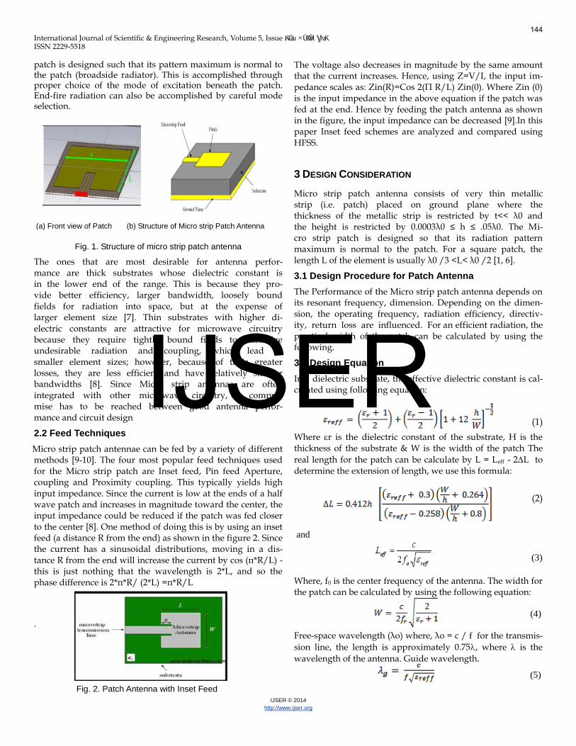
Micro strip patch antennae can be fed by a variety of different methods [9-10]. The four most popular feed techniques used for the Micro strip patch are Inset feed, Pin feed Aperture, coupling and Proximity coupling. This typically yields high input impedance. Since the current is low at the ends of a half wave patch and increases in magnitude toward the center, the input impedance could be reduced if the patch was fed closer to the center [8]. One method of doing this is by using an inset feed (a distance R from the end) as shown in the figure 2. Since the current has a sinusoidal distributions, moving in a dis-tance R from the end will increase the current by cos (π*R/L) - this is just nothing that the wavelength is 2*L, and so the phase difference is 2*π*R/ (2*L) =π*R/L
.
Fig. 2. Patch Antenna with Inset Feed
The voltage also decreases in magnitude by the same amount that the current increases. Hence, using Z=V/I, the input im-pedance scales as: Zin(R)=Cos 2(Π R/L) Zin(0). Where Zin (0) is the input impedance in the above equation if the patch was fed at the end. Hence by feeding the patch antenna as shown in the figure, the input impedance can be decreased [9].In this paper Inset feed schemes are analyzed and compared using HFSS.
3 DESIGN CONSIDERATION
Micro strip patch antenna consists of very thin metallic strip (i.e. patch) placed on ground plane where the thickness of the metallic strip is restricted by t<< λ0 and the height is restricted by 0.0003λ0 ≤ h ≤ .05λ0. The Mi-cro strip patch is designed so that its radiation pattern maximum is normal to the patch. For a square patch, the length L of the element is usually λ0 /3 <L< λ0 /2 [1, 6].
3.1 Design Procedure for Patch Antenna
The Performance of the Micro strip patch antenna depends on its resonant frequency, dimension. Depending on the dimen-sion, the operating frequency, radiation efficiency, directiv-ity, return loss are influenced. For an efficient radiation, the practical width of the patch can be calculated by using the following.
3.2 Design Equation
In a dielectric substrate, the effective dielectric constant is cal-culated using following equation:
(1)
Where r is the dielectric constant of the substrate, H is the thickness of the substrate & W is the width of the patch The
real length for the patch can be calculate by L = Leff - 2L to determine the extension of length, we use this formula:
(2)
and
(3)
Where, f0 is the center frequency of the antenna. The width for the patch can be calculated by using the following equation:
(4)
Free-space wavelength (λo) where, λo = c / f for the transmis-
sion line, the length is approximately 0.75, where is the
wavelength of the antenna. Guide wavelength.
(5)
144
IJSER
International Journal of Scientific & Engineering Research, Volume 5, Issue ƘȮɯ ×ÙÐÓɪƖƔƕƘ ISSN 2229-5518
The actual length, L of patch used the following formula:
(6)
4 Simulation Process
A dielectric substrate RT/duroid 5880 whose permittivity εr = 2.2 is selected for various RMPA. The proposed patch antennas are designed and simulated on HFSS simulation software and fabricated to operate at frequencies 5GHz and 10GHz. All parameters mentioned from equation (1) to equation (6) are computed and tabulated in table 1.
TABLE 1.
CALCULATED DESIGNED VALUES FOR PROPOSED RMPA
5 Figure Captions for Ordinary Fed RMPA
(a) Return Loss
(b) Antenna Geometry
Fig.3. Ordinary Fed Rectangular Patch Antenna at
Frequency 5GHz
6 Simulation, Measured Results and Discussion
The software used to model and simulate the Micro strip patch antennae is High Frequency Simulation Software HFSS version 13. It has been widely used in the design of Patch antennae, Wire antennae, MICs, RFICs, and other RF/wireless antennae designs. It can be used to determine and plot the reflection parameters, Voltage Standing Wave Ratio (VSWR), Radiation patterns, Polar Plots etc. band-width of the simulation and measurements are accom-plished. Since a Microstrip patch antenna radiates normal to
its patch surface, the elevation pattern for = 0 and = 90
degrees would be important. Figures (4e), (5e) & (6e) show the radiation Pattern plots in terms of directivity of the antenna at frequencies 5&10 GHz for various feeding techniques. Gain is improved at frequencies 5&10 GHz by using the inset feed patch antenna. The parameter VSWR is a measure that numerically describes how well the antenna is impedance matched to the radio or transmission line it is connected to. VSWR stands for Voltage Standing Wave Ratio, and is also referred to as Standing Wave Ratio (SWR). VSWR is a function of the reflection coefficient, which describes the power reflect-ed from the antenna. The VSWR is always a real and positive number for antennas. The smaller the VSWR is, the better the antenna is matched to the transmission line and the more power is delivered to the antenna. The minimum VSWR is 1.0. In this case, no power is reflected from the antenna, which is ideal. When a transmitter is connected to an antenna by a feed line, the impedance of the antenna and feed line must match exactly for maximum possible energy transfer from the feed line to the antenna. When an antenna and feed line do not have matching impedances, some of the electrical energy cannot be transferred from the feed line to the antenna. Energy not transferred to the antenna is re-flected back towards the transmitter. It is the interaction of these reflected waves with forward waves which causes standing wave patterns. Ideally, VSWR must lie in the range of 1-2. Measured VSWR at figures (4f), (5f) & (6f) of the frequency range 5 GHz is 1.08 and for the designed RMPA at frequency 10 GHz it is 1.56. A fre-quency band of 1 GHz is selected for each operating frequency and 151frequency points are selected over this range to obtain accurate results. The center frequen-cy is selected as the one at which the return loss is min-imum. The bandwidth of the antenna can be said to be at range of frequencies over which the return loss is greater than -9.5 dB as shown in fig. (3a) for the ordi-nary fed RMPA. Figures (4a), (4b), (5a), (5b) (6a) & (6b) investigate the measured return loss for simulated and fabricated patches. The Return Loss of the 5.4 mm inset center fed rectangular patch antenna at frequency 5GHz records the best performance as it is around 0.1 for the measured and less than 0.025 for the simulated. Figures (4c), (5c) & (6 c) depict the 3D polar plot when φ = 0 and φ = 90 which is simulated using HFSS.
145
IJSER
International Journal of Scientific & Engineering Research, Volume 5, Issue ƘȮɯ ×ÙÐÓɪƖƔƕƘ ISSN 2229-5518
The main and unique feature of this Microstrip antenna is its simplicity to get higher performance. In applica-tions essentially in radar and satellite communication, it is necessary to design antennas with very high directive characteristics to meet the demand of long distance communication. The Inset feed Microstrip patch anten-nae has been designed and simulated using high fre-quency simulation software HFSS. The simulation re-sults show that the Inset feed excitation technique pro-vides more enhanced characteristics and perfect imped-ance matching as compared to the other feed excitation techniques and at different feeding locations. Also the main advantage of this feeding technique is that feed can be given anywhere inside the patch which makes easier fabrication compared to other feed techniques. In future Micro strip patch antenna array will be designed for the same operating frequency ranges in order to achieve the maximum gain. Fabrication clarifies how to obtain the best possible match for center feeding Micro strip line as well with a maximum deviation of 0.3% from the centre.
REFERENCES
[1] Microstrip Antennas," IEEE International Symposium on Antennas
and Propagation, Williamsburg Virginia, 1972 pp. 177-180
[2] N. Kanniyappan, Dr.R. Indra Gandhi, “Design and Analysis of Micro
strip Patch Antenna Feeding Techniques”, IEEE proceedings of In-
ternational Conference on Computational Intelligence and Compu-
ting Research’2011
[3] Microstrip and Printed Antenna Design" (2nd Edition) Randy Ban-
croft SciTech Publishing Inc. 2009.
[4] Antenna Theory (3rd Edition), C. Balanis, Wiley 2005
[5] Antenna Engineering Handbook, ed. R. Johnson, McGraw-Hill 1993
[6] K.A. Carver and J.A. Mink, "Microstrip antenna technology," IEEE
Transactions on Antennas & Propagation, Vol. 29, January 1981, pp.
2-24.
[7] H. Pues and A. Van De Capelle, "Accurate transmission line model
for the rectangular microstrip antenna," IEEE Proceedings on Micro-
waves, Optics & Antennas, Vol. 134, 1984, pp. 334−340.
[8] David M. Pozar, "Input impedance and mutual coupling of
rectangular microstrip antennas,"IEEE Transactions on Antennas &
Propagation, Vol. AP-30, November 1982, pp. 1191-1196.
[9] M A Matin, A. I. Sayeed, “A Design Rule for Inset-fed Rectangular
Micro strip Patch Antenna” in International Conference on Wseas
Transactions On Communications, ISSN: 1109-2742 Bangladesh Issue
1, Volume 9, and January 2010 March 21-23, 2011.
[10] Priya Upadhyay, Richa Sharma, "Design and Study of Inset Feed
Square Microstrip Patch Antenna for S-Band Applica-
tion," International Journal of Application or Innovation in Engi-
neering & Management (IJAIEM) Vol. 2, January 2013, pp. 256-261.
Fig. 4. Inset Center Deviated Fed Rectangular Patch Antenna
at f = 5GHz
146
IJSER
International Journal of Scientific & Engineering Research, Volume 5, Issue ƘȮɯ ×ÙÐÓɪƖƔƕƘ ISSN 2229-5518