Performance Enhancement ofMicroturbine Engines ToppedWith Wave RotorsSignificant performance enhancement of microturbines is predicted by implementing vari-ous wave-rotor-topping cycles. Five different advantageous cases are considered forimplementation of a four-port wave rotor into two given baseline engines. In these ther-modynamic analyses, the compressor and turbine pressure ratios and the turbine inlettemperatures are varied, according to the anticipated design objectives of the cases.Advantages and disadvantages are discussed. Comparison between the theoretic perfor-mance of wave-rotor-topped and baseline engines shows a performance enhancement upto 34%. General design maps are generated for the small gas turbines, showing thedesign space and optima for baseline and topped engines. Also, the impact of ambienttemperature on the performance of both baseline and topped engines is investigated. It isshown that the wave-rotor-topped engines are less prone to performance degradationunder hot-weather conditions than the baseline engines. �DOI: 10.1115/1.1924484�
IntroductionA growing market for distributed power generation and propul-
sion of small vehicles has motivated a strong interest in design ofsmall gas turbine systems in the range of 30–300 kW. Known asmicroturbines, they are now widely used in the US for distributedpower generation, shaving peak loads, and providing backuppower for critical needs. They propel small commercial aircraft,unmanned air vehicles �UAV�, and terrestrial vehicles. Microtur-bines are often the preferred alternative to IC engines, because oftheir higher power density and robustness. They present severaladvantageous features such as compact size, simple operability,ease of installation, low maintenance, fuel flexibility, and lowNOX emissions. Furthermore, recent electric-power crises and en-vironmental concerns have stimulated a strong interest in the re-search, development, and application of microturbines.
Despite their attractive features, compared with larger gas tur-bines, microturbines suffer from lower thermal efficiency andtheir relative output power, due to their �lower� component effi-ciencies, limited cycle pressure ratio, and peak cycle temperature.For example, experimental and theoretical research has shownthat microturbines with pressure ratios of 3–5 without recupera-tion systems achieve only about 15%–20% efficiency �1,2�. Formany applications improvement of their performance is desirableto enhance advantages over competing technologies. To achievesuch improvements, current efforts are mainly focused on utilizingheat recovery devices, developing new high-strength, high-temperature materials for turbine blades, and improving the aero-dynamic quality of turbomachinery components �3�. The aerody-namics of turbomachinery has already yielded very highcomponent efficiencies up to around 90% �4�. Further improve-ment is possible, but huge gains seem unlikely especially forsmall compressors with unavoidable tip leakage. Geometries ofmicroturbines make blade cooling very difficult and internal cool-ing methods applied to larger engines are often impractical forsmaller turbines. Hence, their lifetimes are shorter when usingmaterials typical of larger gas turbines �5�. Therefore, there issignificant research toward developing advanced metallic alloysand ceramics for high-thermal-resistance turbine wheels used in
Contributed by the IGTI Microturbines and Small Turbomachinery Committee ofthe ASME for publication in the JOURNAL OF ENGINEERING FOR GAS TURBINES AND
POWER. Manuscript received March 12, 2004; final manuscript received December
microturbines �6,7�. Utilizing conventional recuperators based onthe use of existing materials can improve the overall efficiency ofmicroturbines up to 30% �2,8–10�. Despite the attractive featureof the recuperator concept, a recuperator adds about 25%–30% tothe overall engine manufacturing cost, which is a challenge forcommercialization of microturbines �11–13�. The current trend ofthe microturbine market is to reduce the investment cost. There-fore, alternative devices need to be considered to achieve higherperformance at lower component costs. Topping a microturbinewith a wave rotor device is an appropriate solution.
In a wave-rotor-topped cycle, the combustion can take place ata higher temperature while the turbine inlet temperature can beequal to that of the baseline cycle. Also, a pressure gain additionalto that provided by the compressor is obtained by the wave rotor.Thus, the wave rotor can increase the overall pressure ratio andpeak cycle temperature beyond the limits of ordinary turboma-chinery. The performance enhancement is achieved by increasingboth thermal efficiency and output work, hence reducing specificfuel consumption rate considerably. This enhancement is espe-cially favorable for smaller gas turbines often used for distributedpower generation or propulsion of small vehicles �14–17�.
Wave Rotor History. The first successful wave rotor wastested by Brown Boveri Company �BBC�, later Asea BrownBoveri �ABB�, in Switzerland in the beginning of the 1940s �18�as a topping stage for a locomotive gas turbine engine �19–22�,based on the patents of Seippel �23–26�. This first unit sufferedfrom inefficient design and crude integration �21�. Later, BBCfocused on the development of pressure wave superchargers fordiesel engines, anticipating greater payoff �27�. By 1987, theirComprex® supercharger appeared in the Mazda 626 Capella pas-senger car �28,29�. Since then, the Comprex® has been commer-cialized for heavy diesel engines, and also tested successfully onvehicles such as Mercedes-Benz �30�, Peugeot, and Ferrari �27�.Such a pressure-wave supercharger offers rapid load response andscale-independent efficiency, making its light weight and compactsize attractive for supercharging small engines �below about 75kW or 100 hp� �31,32�.
Propulsion applications resumed in the 1960s, with GeneralElectric Company �GE�, General Power Corporation �GPC�,Mathematical Science Northwest �MSNW�, and Rolls Royce de-veloping prototypes �27,33�. In the 1980s, US agencies like theDefense Advanced Research Projects Agency �DARPA� and the
Navy sponsored research programs on wave rotor science and
2006 by ASME Transactions of the ASME
technology. The 1985 ONR/NAVAIR Wave Rotor Research andTechnology Workshop �33� offered a comprehensive review ofprior work.
Since the late 1980s, a sustained research program at NASAGlenn Research Center �GRC� collaborating with the US ArmyResearch Laboratory �ARL� and Rolls-Royce Allison has aimed todevelop and demonstrate the benefits of wave rotor technology forfuture aircraft propulsion systems �34–40�. Experimental studiesat NASA on four-port �41� and three-port �42–44� wave rotorsenabled the estimation of loss budgets �45,46� and simulationcode validation �47�. Initially, a simple three-port flow dividerwave rotor was built and tested to evaluate loss mechanisms andcalibrate the simulation code. Next, a four-port pressure ex-changer was built and was tested to evaluate the pressure-gainperformance for application to a small gas turbine �Allison 250�.Wave rotor cycles with lower thermal loads have been proposed�48,49�, and mechanical design issues are being addressed in cur-rent NASA-sponsored research.
The French National Aerospace Research Establishment�ONERA� has also investigated wave rotor enhancement of gasturbines in auxiliary power units, turboshaft, turbojet, and turbo-fan engines �15�. Consistent with NASA studies �50�, ONERAanticipates the largest gains and efficiency for engines with a lowcompressor pressure ratio and high turbine inlet temperature, suchas turboshaft engines and auxiliary power units.
The objective of the present work is a comprehensive and sys-tematic performance analysis of two actual microturbines knownas the C-30 and C-60 engines which are topped with a four-portwave rotor in various wave-rotor-topping cycles. The challengesand advantages associated with the different implementation casesare discussed. While the performance evaluation of several gasturbine engines has been studied extensively �14,15,50�, to theknowledge of the author, there exits no comprehensive work in-vestigating the potential benefits of various implementation casesof wave rotor topping cycles for small gas turbines. The presentedresults have been obtained using basic thermodynamic equationsalong with the wave-rotor characteristic equation previously vali-dated using computational tools �14�. The model can be employedto predict the performance improvement of various wave-rotor-topping cycles without the need for knowing the details of thecomplex fluid mechanics within the wave rotor.
Wave Rotor DescriptionWave rotors do not use mechanical components such as pistons
or vaned impellers to compress the fluid. Instead, the pressure riseis obtained by generating compression waves in appropriate ge-ometries. It has been proven that for the same inlet and outletMach numbers the pressure gain in time-dependent flow devicescan be much greater than in steady flow devices �51–53�.
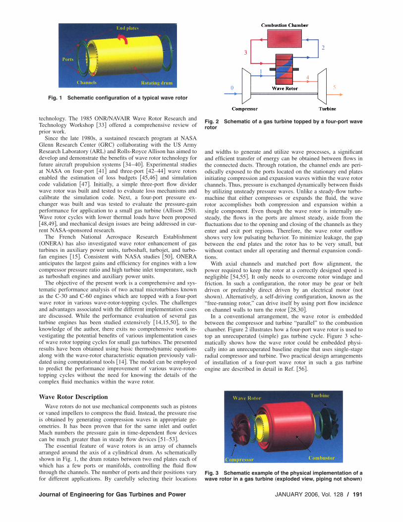
The essential feature of wave rotors is an array of channelsarranged around the axis of a cylindrical drum. As schematicallyshown in Fig. 1, the drum rotates between two end plates each ofwhich has a few ports or manifolds, controlling the fluid flowthrough the channels. The number of ports and their positions vary
Fig. 1 Schematic configuration of a typical wave rotor
for different applications. By carefully selecting their locations
Journal of Engineering for Gas Turbines and Power
and widths to generate and utilize wave processes, a significantand efficient transfer of energy can be obtained between flows inthe connected ducts. Through rotation, the channel ends are peri-odically exposed to the ports located on the stationary end platesinitiating compression and expansion waves within the wave rotorchannels. Thus, pressure is exchanged dynamically between fluidsby utilizing unsteady pressure waves. Unlike a steady-flow turbo-machine that either compresses or expands the fluid, the waverotor accomplishes both compression and expansion within asingle component. Even though the wave rotor is internally un-steady, the flows in the ports are almost steady, aside from thefluctuations due to the opening and closing of the channels as theyenter and exit port regions. Therefore, the wave rotor outflowshows very low pulsating behavior. To minimize leakage, the gapbetween the end plates and the rotor has to be very small, butwithout contact under all operating and thermal expansion condi-tions.
With axial channels and matched port flow alignment, thepower required to keep the rotor at a correctly designed speed isnegligible �54,55�. It only needs to overcome rotor windage andfriction. In such a configuration, the rotor may be gear or beltdriven or preferably direct driven by an electrical motor �notshown�. Alternatively, a self-driving configuration, known as the“free-running rotor,” can drive itself by using port flow incidenceon channel walls to turn the rotor �28,30�.
In a conventional arrangement, the wave rotor is embeddedbetween the compressor and turbine “parallel” to the combustionchamber. Figure 2 illustrates how a four-port wave rotor is used totop an unrecuperated �simple� gas turbine cycle. Figure 3 sche-matically shows how the wave rotor could be embedded physi-cally into an unrecuperated baseline engine that uses single-stageradial compressor and turbine. Two practical design arrangementsof installation of a four-port wave rotor in such a gas turbineengine are described in detail in Ref. �56�.
Fig. 2 Schematic of a gas turbine topped by a four-port waverotor
Fig. 3 Schematic example of the physical implementation of a
wave rotor in a gas turbine „exploded view, piping not shown…
JANUARY 2006, Vol. 128 / 191
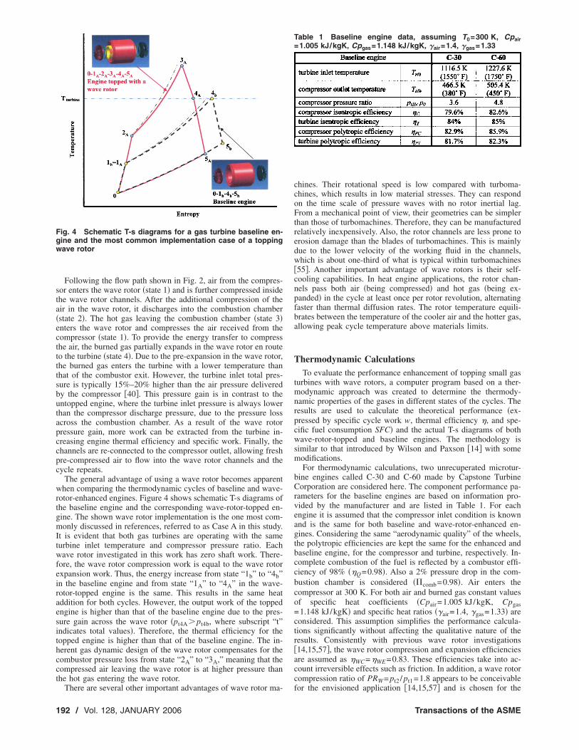
Following the flow path shown in Fig. 2, air from the compres-sor enters the wave rotor �state 1� and is further compressed insidethe wave rotor channels. After the additional compression of theair in the wave rotor, it discharges into the combustion chamber�state 2�. The hot gas leaving the combustion chamber �state 3�enters the wave rotor and compresses the air received from thecompressor �state 1�. To provide the energy transfer to compressthe air, the burned gas partially expands in the wave rotor en routeto the turbine �state 4�. Due to the pre-expansion in the wave rotor,the burned gas enters the turbine with a lower temperature thanthat of the combustor exit. However, the turbine inlet total pres-sure is typically 15%–20% higher than the air pressure deliveredby the compressor �40�. This pressure gain is in contrast to theuntopped engine, where the turbine inlet pressure is always lowerthan the compressor discharge pressure, due to the pressure lossacross the combustion chamber. As a result of the wave rotorpressure gain, more work can be extracted from the turbine in-creasing engine thermal efficiency and specific work. Finally, thechannels are re-connected to the compressor outlet, allowing freshpre-compressed air to flow into the wave rotor channels and thecycle repeats.
The general advantage of using a wave rotor becomes apparentwhen comparing the thermodynamic cycles of baseline and wave-rotor-enhanced engines. Figure 4 shows schematic T-s diagrams ofthe baseline engine and the corresponding wave-rotor-topped en-gine. The shown wave rotor implementation is the one most com-monly discussed in references, referred to as Case A in this study.It is evident that both gas turbines are operating with the sameturbine inlet temperature and compressor pressure ratio. Eachwave rotor investigated in this work has zero shaft work. There-fore, the wave rotor compression work is equal to the wave rotorexpansion work. Thus, the energy increase from state “1b” to “4b”in the baseline engine and from state “1A” to “4A” in the wave-rotor-topped engine is the same. This results in the same heataddition for both cycles. However, the output work of the toppedengine is higher than that of the baseline engine due to the pres-sure gain across the wave rotor �pt4A� pt4b, where subscript “t”indicates total values�. Therefore, the thermal efficiency for thetopped engine is higher than that of the baseline engine. The in-herent gas dynamic design of the wave rotor compensates for thecombustor pressure loss from state “2A” to “3A,” meaning that thecompressed air leaving the wave rotor is at higher pressure thanthe hot gas entering the wave rotor.
Fig. 4 Schematic T-s diagrams for a gas turbine baseline en-gine and the most common implementation case of a toppingwave rotor
There are several other important advantages of wave rotor ma-
192 / Vol. 128, JANUARY 2006
chines. Their rotational speed is low compared with turboma-chines, which results in low material stresses. They can respondon the time scale of pressure waves with no rotor inertial lag.From a mechanical point of view, their geometries can be simplerthan those of turbomachines. Therefore, they can be manufacturedrelatively inexpensively. Also, the rotor channels are less prone toerosion damage than the blades of turbomachines. This is mainlydue to the lower velocity of the working fluid in the channels,which is about one-third of what is typical within turbomachines�55�. Another important advantage of wave rotors is their self-cooling capabilities. In heat engine applications, the rotor chan-nels pass both air �being compressed� and hot gas �being ex-panded� in the cycle at least once per rotor revolution, alternatingfaster than thermal diffusion rates. The rotor temperature equili-brates between the temperature of the cooler air and the hotter gas,allowing peak cycle temperature above materials limits.
Thermodynamic CalculationsTo evaluate the performance enhancement of topping small gas
turbines with wave rotors, a computer program based on a ther-modynamic approach was created to determine the thermody-namic properties of the gases in different states of the cycles. Theresults are used to calculate the theoretical performance �ex-pressed by specific cycle work w, thermal efficiency �, and spe-cific fuel consumption SFC� and the actual T-s diagrams of bothwave-rotor-topped and baseline engines. The methodology issimilar to that introduced by Wilson and Paxson �14� with somemodifications.
For thermodynamic calculations, two unrecuperated microtur-bine engines called C-30 and C-60 made by Capstone TurbineCorporation are considered here. The component performance pa-rameters for the baseline engines are based on information pro-vided by the manufacturer and are listed in Table 1. For eachengine it is assumed that the compressor inlet condition is knownand is the same for both baseline and wave-rotor-enhanced en-gines. Considering the same “aerodynamic quality” of the wheels,the polytropic efficiencies are kept the same for the enhanced andbaseline engine, for the compressor and turbine, respectively. In-complete combustion of the fuel is reflected by a combustor effi-ciency of 98% ��Q=0.98�. Also a 2% pressure drop in the com-bustion chamber is considered ��comb=0.98�. Air enters thecompressor at 300 K. For both air and burned gas constant valuesof specific heat coefficients �Cpair=1.005 kJ/kgK, Cpgas=1.148 kJ/kgK� and specific heat ratios ��air=1.4, �gas=1.33� areconsidered. This assumption simplifies the performance calcula-tions significantly without affecting the qualitative nature of theresults. Consistently with previous wave rotor investigations�14,15,57�, the wave rotor compression and expansion efficienciesare assumed as �WC=�WE=0.83. These efficiencies take into ac-count irreversible effects such as friction. In addition, a wave rotorcompression ratio of PRW= pt2 / pt1=1.8 appears to be conceivable
for the envisioned application �14,15,57� and is chosen for the
Transactions of the ASME
following discussion. In this work all performance plots areshown for various wave rotor pressure ratios indicating its effecton the performance enhancement.
Implementation Cases. There are several possibilities to top agas turbine with a wave rotor. Considering possible design restric-tions and preferences, five different advantageous implementationcases for a wave rotor into a given baseline engine can be intro-duced as follows:
Case A: same compressor, same turbine inlet temperatureCase B: same overall pressure ratio, same turbine inlet
temperatureCase C: same combustorCase D: same turbineCase E: same compressor, same combustion end temperatureCase A: In Case A the pressure ratio of the compressor is kept
unchanged, so the physical compressor of the baseline engine canalso be used for the wave-rotor-enhanced engine provided themass flow is kept approximately the same. The pressure in thecombustion chamber of the enhanced engine is increased by thecompression ratio of the wave rotor. This may require modifica-tions to the structure of the combustion chamber and to the fuelinjection system. The heat addition in the combustor is the sameas for the baseline engine, but it takes place after the energy ex-change in the wave rotor, hence the heat addition starts at a highertemperature. Thus, the combustion end temperature is even higherthan that of the baseline engine, possibly requiring additionally athermal enhancement of the combustor structure. The turbine ofthe topped engine might need to be adapted to efficiently utilizethe higher pressure ratio. The turbine inlet temperature, however,is the same as that of the baseline engine. As will be shown later,this implementation case provides the highest thermal efficiencyand specific work and the lowest value of SFC. However, con-cerns may be raised concerning emissions and combustor designdue to the elevation of combustor pressure and temperature.Therefore, other topping cycles might be preferred which are dis-cussed below.
Case B: In Case B the overall pressure ratio for the wave-rotor-enhanced engine is kept equal to that of the baseline engine, sothat the combustor works under the same pressure. However, forthe wave-rotor-topped engine, the heat addition in the combustorand the combustion end temperature are greater than those of thebaseline engine. This may require some adaptation of the combus-tor, especially in the outlet region. The turbine and compressorwork with lower pressure ratios, reducing the design challenges.Thus, both may be adapted advantageously. This might reduce thecost of the compressor and turbine due to reduction of stages inmultistage types �mostly axial�, or due to reduction of the tipdiameter in radial types �mostly single-stage�. With a smaller tipdiameter the wheels can be manufactured more economically overa shorter time from cheaper materials with less strength and onsmaller machines. Besides an attractive performance enhance-ment, this case additionally provides the highest turbine outlettemperature of all five cases investigated. The temperature of theleaving exhaust gas is much higher than that of the baseline en-gine. Therefore, this case is attractive for an external heat recov-ery application or for internal recuperation that can enhance theperformance further.
Case C: Case C assumes that it is desirable for the wave-rotor-enhanced engine to use the unmodified combustor of the baselineengine. So the overall pressure ratio and combustor inlet and out-let temperatures for the wave-rotor-enhanced engine are keptequal to those of the baseline engine. The heat addition in thecombustor is consequently the same.1 The implementation of thewave rotor considerably reduces the pressure ratio of the turbine
1The wave rotor compression efficiency is greater than the compressor efficiency.Therefore, the combustor inlet temperature is in fact negligibly smaller and hence the
heat addition is negligibly greater than that in the baseline engine.
Journal of Engineering for Gas Turbines and Power
and compressor. The compressor pressure ratio is as low as inCase B, and the turbine pressure ratio and turbine inlet tempera-ture are even lower than those in Case B. Thus, the turbine andcompressor could be made from less thermally resistant material.Compared to the baseline engine, they also could be smaller andhence less expensive, as discussed in Case B. This might be themain implementation reason because unfortunately, but not sur-prisingly, the unambitious combustor constrains the performanceenhancement. It is nearly negligible for the smaller C-30 engineand even negative for the C-60 engine.
Case D: Case D employs the same physical turbine as the base-line engine. Due to the wave-rotor-topping, the compressor needsto produce a lower pressure ratio than that of the baseline engine.This allows for a smaller and less expensive compressor as dis-cussed for Cases B and C. The pressure in the combustion cham-ber and the combustion end temperature are higher than those ofthe baseline engine, but lower than those of Case A. Hence, lesseffort might be required to adapt the structure and fuel injection ofthe combustion chamber. As a result of the lower pressure ratio inthe compressor, hence lower compressor discharge temperature,the heat addition in the combustor has to be more than that for thebaseline engine to utilize the same allowed turbine inlet tempera-ture. This case gives the second highest performance increase forboth baseline engines.
Case E: Case E is similar to Case A but the combustion endtemperature �the cycle peak temperature� is restricted to the tur-bine inlet temperature of the baseline engine in order to avoidadditional thermal requirements on the combustor design. Theoverall pressure ratio is the same as in Case A because this caseemploys the same physical compressor as for the baseline engine.Thus, the overall pressure ratio is greater than that of the baselineengine, by the wave rotor pressure ratio. The heat addition in thecombustor is less than that for the baseline engine because to thewave rotor compression work is added to the fluid before com-bustion. The turbine in the topped cycle works with a slightlygreater pressure ratio than the turbine of the baseline engine, butthe turbine inlet temperature is less than that for the baseline en-gine. In fact, it is the lowest of all cases investigated. This maygive the option to produce the turbine wheel at a lower cost out ofless thermally resistant material.
According to the state numbering introduced in Fig. 2, Fig. 5visualizes all five cases in schematic T-s diagrams. Path0-1b-4b-5b represents the baseline cycle and 0-1i-2i-3i-4i-5i �i=A, B, C, D, E� indicates the wave-rotor-topped cycles, where thesubscripts indicate the case. One of the five cases might be pref-
Fig. 5 Schematic T-s diagrams for a baseline cycle and fivedifferent wave-rotor-topped cycles
erable for a practical design, however, intermediate design cases
JANUARY 2006, Vol. 128 / 193
are possible. In the following it is assessed how the wave-rotor-topping enhances the performance of C-30 and C-60 baseline gasturbine engines.
Analytical Procedure. According to state numbering intro-duced in Fig. 2, the following steps are taken to calculate thethermodynamic properties of the gases in different states of thetopped cycle:
Path 0-1: Compressor. With the given compressor inlet tem-perature �T0=Tt0�, the compressor outlet total temperature andpressure are calculated from the adiabatic relations:
Tt1 = Tt0 +Tt0
�C
��C
�air−1
�air − 1� �1�
pt1
p0=
pt1
pt0= �C �2�
where the compressor isentropic efficiency ��C� relates the com-pressor pressure ratio ��C� to the compressor polytropic effi-ciency ��PC� through:
�C =�C
�air−1
�air − 1
�C
�air−1
�air�PC − 1
�3�
For Cases A and E, the compressor pressure ratio is equal to thatof the baseline engine �e.g., for C-30 engine �C=3.6 and for C-60engine �C=4.8�. However, for Cases B and C its value is calcu-lated by dividing the baseline compressor pressure ratio with thewave rotor compression ratio �PRW�. For Case E, the value of �Cis calculated in a way that keeps the pressure at the turbine inletequal for both baseline and topped engines. This calculation canbe performed by inversely solving of Eqs. �1�–�21�. The compres-sor specific work is obtained by:
wC = Cpair�Tt1 − Tt0� =CpairTt0
�C��C
�air−1
�air − 1� �4�
Path 1-2: Compression in the Wave Rotor. The flow propertiesafter the wave rotor compression process are obtained from theadiabatic relations similarly to those of the compressor:
Tt2 = Tt1 +Tt1
�WC�PRW
�air−1
�air − 1� �5�
pt2
pt0=
pt2
pt1
pt1
pt0= PRW · �C �6�
Path 2-3: Combustion Chamber. The value of fuel–air ratio�f =mf /mair� can be obtained by applying the energy �first law�equation to the combustion chamber:
�Q f hPR = �1 + f�CpgasTt3 − CpairTt2 �7�
where hPR=43,000 kJ/kg is the heating value used for all calcu-lations here. This equation gives f as:
f =CpgasTt3 − CpairTt2
�Q hPR − CpgasTt3�8�
Alternatively, f can be expressed based on the turbine total inlettemperature �Tt4� and the compressor total exit temperature �Tt1�.For this purpose, the wave rotor compression and expansion spe-cific work �per unit mass of air flow� are defined, respectively, asfollows:
wWC = Cpair�Tt2 − Tt1� �9�
194 / Vol. 128, JANUARY 2006
wWE = �1 + f�Cpgas�Tt3 − Tt4� �10�
Here, it is considered that m1= m2= mair and m3= m4= mair+ mf.Other cycles exist in which the mass flow rates m1 and m2 are notthe same, and, correspondingly the mass flow rates m3 and m4may not be equal either. These cycles are not considered here.Using Eqs. �9� and �10�, Eq. �7� can be expressed as:
�Q f hPR = �1 + f�CpgasTt4 + wWE − wWC − CpairTt1 �11�
Because the net output work of the wave rotor is zero �wWC=wWE�, solving for f leads to:
f =CpgasTt4 − CpairTt1
�Q hPR − CpgasTt4�12�
For Cases C and E, Tt3 is equal to the baseline inlet turbine tem-perature, therefore, Eq. �8� is used to calculate f . For Cases A, B,and D, where Tt4 is a known value and is equal to the baselineinlet turbine temperature, f can be obtained from Eq. �12�. Therelation between Tt3 and Tt4 can be found by equating Eqs. �9� and�10�:
Tt3 = Tt4 + � Tt1
�WC�PRW
�air−1
�air − 1�� Cpair
�1 + f�Cpgas�13�
Finally, the total pressure after the combustion chamber is ob-tained by:
pt3
pt0=
pt3
pt2
pt2
pt0= �comb · PRW · �C �14�
Path 3-4: Expansion in the Wave Rotor. To obtain the turbineinlet total pressure �pt4�, it is convenient to express the wave rotorcompression work and the expansion work in terms of pressureratios:
where PO= pt4 / pt1 is the gain pressure ratio across the wave rotor.Equating the compression work to the expansion work leads to:
CpairTt1
�WC�PRW
�air−1
�air − 1� = �1 + f�Cpgas�WETt3
��1 − � PO
�combPRW��gas−1/�gas�
�17�
Substituting Tt3 from Eq. �13� into Eq. �17� and some algebragives:
PO = �combPRW1 −A 1
�WE�WCB
1 + A 1�WC
B�gas/�gas−1
�18�
where
A =Cpair
�1 + f�Cpgas�19�
B =Tt1
Tt4�PRW
��air−1�/�air − 1� �20�
Equation �18� is a modified version of the “wave-rotor character-istic” equation introduced in the literature �14�. This equation rep-resents the performance of the wave rotor. By using Eq. �18�, the
turbine inlet total pressure is obtained by:
Transactions of the ASME
rat
pt4
pt0=
pt4
pt1
pt1
pt0= PO · �C �21�
Path 3-4: Turbine. The turbine specific work �per unit mass ofair flow� can be calculated knowing the pressure ratio across theturbine:
Assuming the turbine expands the hot gas leaving the wave rotorto atmospheric pressure �pt5= pt0�. As a result, the total tempera-ture of the gas leaving the turbine �Tt5� can be calculated from theabove equation.
After calculating the thermodynamic properties of all states inthe cycle, it is possible to calculate the engine performance pa-rameters. The net specific output work produced by the engine canbe calculated by subtracting the turbine specific work from thecompressor work as w=wT−wC. With the amount of specific heataddition through the combustion process being defined as q= f .hPR, the thermal efficiency can be written as �=w /q. Finally,the specific fuel consumption �SFC� is calculated by SFC= f /w.
Predicted Performance ResultsCase A is the most common case discussed in the literature and
it gives mostly the best performance enhancement. Therefore, it isdiscussed here in more details. Figure 6 illustrates the increase ofcycle thermal efficiency �dash dot� and specific work �dashed�,and the decrease of specific fuel consumption �solid� with increas-ing wave rotor pressure ratio PRW for both C-30 and C-60 toppedengines. The plot visualizes how the effect develops from thebaseline engine with PRW=1 until PRW=2 which might be a prac-tical limit for the investigated application. However, if the waverotor pressure ratio increases beyond this limit, the trend alreadyshows that the rate of increase of the effect diminishes whiletechnical problems may increase. With a conceivable wave rotorpressure ratio of 1.8, the thermal efficiency of the baseline cycleincreases from 14.9% to 20.0% for the C-30 engine and from19.4% to 24.2% for the C-60 engine. Simultaneously, the specificwork increases from 128 to 171 kJ/kg for the C-30 engine andfrom 184 to 231 kJ/kg for the C-60 engine. The specific fuelconsumption �SFC� of the C-30 engine decreases from 0.156 to0.116 kg/kN.s and it reduces from 0.120 to 0.095 kg/kN.s for
Fig. 6 Thermal efficiency, specific work, and Swave rotor pressure ratio and overall pressure
the C-60 engine.
Journal of Engineering for Gas Turbines and Power
A better picture of the performance improvement is obtained bycalculating the relative increases of thermal efficiency, specificwork, and the relative decrease of SFC as shown in Fig. 7. ForCase A, the relative increases of thermal efficiency and specificwork �dash–dot� are precisely the same as it is obvious from �=w /q where the heat addition q= f .hPR is the same for bothtopped and baseline engines. For a wave rotor pressure ratio of1.8, Fig. 7 indicates an attractive relative performance improve-ment in thermal efficiency and specific work of about 33.8% anda 25.2% reduction in SFC �solid� for the C-30 engine. The C-60engine shows a 25.1% enhancement in thermal efficiency andspecific work and a 20.1% reduction in SFC.
More detailed documentation of these cases are not presentedhere. The reader is referred to Ref. �16�. Instead, numerical valuesof the predicted performance enhancement of all five investigatedcases with a wave rotor pressure ratio of 1.8 are summarized inTable 2. In this table, �T represents the turbine pressure ratio.Subscript “gain” indicates the relative increase of thermal effi-ciency and specific work and decrease of SFC. Table 2 shows thatCase A gives the highest performance increase for both baselineengines. After Case A, Case D gives the highest overall perfor-mance for the C-30 engine as for the C-60 engine. However, CaseE provides the second highest thermal efficiency and the lowestSFC for the C-60 engine.
Figure 8 shows maps of the relevant design space for Cases A,B, and D for each engine. The only fixed parameters are turbineinlet temperature, the polytropic efficiencies of the compressorand turbine corresponding to the respective baseline engine, andthe combustion chamber pressure loss as indicated in the upper-right hand corner legend of each map. Performance maps valid forCases C and E of the C-30 and the C-60 engines are shown in Fig.9 which have lower turbine inlet temperatures than that indicatedin Fig. 8. Instead, Cases C and E have the same combustion endtemperature as the baseline engine, as indicated in the upper-righthand corner of these maps.
The maps allow predicting the performance of the wave-rotor-enhanced engine in terms of thermal efficiency �green�, specificwork �blue�, and SFC �red� for any combination of the compressorpressure ratio �abscissa� and the wave rotor pressure ratio PRW�parameter labeled in black�. In these maps, the multiplication ofcompressor pressure ratio pt1 / p0 and wave rotor pressure ratioPRW determines the overall cycle pressure ratio pt2 / p0 �orange�.The locus of optimum compressor pressure ratio points �for high-est thermal efficiency and specific work at each achievable waverotor pressure ratio� are connected by black solid lines. The op-
for the wave-rotor-topped engines versus theio, Case A consideration
FC
tima for SFC are found at the same combination of the compres-
JANUARY 2006, Vol. 128 / 195
sor pressure ratio and PRW as the optima of the thermal efficiency.Such maps are not only very useful to explore the possible
enhancement of already existing baseline engines, but they alsoserve well for selecting a design point or region for designing anew wave-rotor-topped engine. In all plots, the performancepoints of the baseline engine �PRW=1� and the wave-rotor-enhanced engines of all cases with a wave rotor pressure ratio ofPRW=1.8 can be found. For instance in Fig. 8, starting from theperformance point of the baseline engine, the performance valuesfor Case A are found by moving vertically upwards �e.g., alongthe dashed line for constant compressor pressure ratio pt1 / p0� un-til the corresponding performance curve of the expected waverotor pressure ratio is crossed. Case B is found by moving along aline of constant overall pressure ratio pt2 / p0 �orange�.
The results indicate that for every compressor pressure ratio ineach design space shown here, the performance of the toppedengine is always higher than that of the corresponding baselineengine with the same compressor pressure ratio �Case A consid-eration�. The increase of PRW always increases the performance.However, for higher compressor pressure ratios the benefit of us-ing a wave rotor progressively diminishes. In fact, for compressor
Fig. 7 Relative values of thermal efficienctopped engines versus the wave rotor presconsideration
Table 2 Performance comparison between btopping with a wave rotor pressure ratio of 1.
196 / Vol. 128, JANUARY 2006
pressure ratios greater than around 11, almost no benefit can beobtained for the C-30 engine. An identical statement applies to theC-60 engine for compressor pressure ratios above around 15. Thebenefit is clearly the greatest for lower compressor pressure ratios.This suggests that the wave-rotor-topping for microturbines withlow compressor pressure ratios can produce the greatest relativebenefit. Moreover, as expected and known for baseline engines�PRW=1�, it is also true for wave-rotor-topped engines that thecompressor pressure ratio for the maximum specific work is al-ways less than that of the maximum thermal cycle efficiency.However, with increasing wave rotor pressure ratio, the optimacome closer together, while moving towards lower compressorpressure ratio. This can be viewed as an additional advantage forapplying wave rotors to small gas turbines with low compressorpressure ratios. So as the plots show, adding a wave rotor with a1.8 pressure ratio to C-30 or C-60 baseline engines with a com-pressor pressure ratio pt1 / p0=3.6 or pt1 / p0=4.8, respectively, al-ready brings the design point into the optimum range for highestspecific work and nearly half way closer to the optimum for high-est thermal efficiency.
pecific work, and SFC for the wave-rotor-re ratio and overall pressure ratio, Case A
eline engines and five cases of wave-rotor-
y, ssu
as8
Transactions of the ASME
top
Comparison Between Adding a Second Compressor Stageand Wave-Rotor-Topping. The wave-rotor-topping competesmainly against adding a second compressor stage to the singlestage baseline engine. In this competition one major advantage ofthe wave-rotor-topping is that the wave rotor favorably operatesmechanically independently from the high-speed engine shaft.Therefore, adding a retrofit wave rotor does not require the rede-sign of the challenging dynamic system. Even if the compressoror turbine wheel is adapted subsequently to utilize the full poten-tial of the wave-rotor-topping, the dynamic system may changebut not as dramatically as if a second compressor stage was added.Thus, by default the wave rotor is a system for achieving similarthermodynamic advantages as by adding a second compressorstage or a high pressure spool, but with many fewer dynamicchallenges.
To justify the wave-rotor-topping approach further, the perfor-mance results of both competing solutions are compared below.For the addition of a second compressor stage, performance dataare calculated for the five most probably relevant pressure ratiosof the second stage described here:
�c2 = PRW.
A �perhaps� logical way to compare both systems would be toassume the same compression ratio for the second compressor
Fig. 8 Performance map for wave-rotor-
Fig. 9 Performance map for wave-rotor-to
Journal of Engineering for Gas Turbines and Power
stage as for the wave rotor. Hence the compression ratio of thesecond compressor stage would be �c2=1.8, because the assumedwave rotor compression ratio is PRW=1.8.
wC2 = wC1
More likely, when the effort of adding a second compressor stageis undertaken, the designer would not limit the pressure ratio ofthe second stage to �C2=1.8. It might be desired to a add secondcompressor wheel that is similar to the existing first stage �or thesame� for reasons such as using existing experience, or producingboth wheels cost effectively as identical wheels, or producingthem geometrically similar using the same or slightly modifiedtools. This approach can be modeled by setting the compressorshaft work of the second stage equal to that of the first stage,simulating the same angular momentum change of the flow inboth stages at the same shaft. Because the inlet air temperature forthe second stage is much higher, the pressure ratio of the secondstage is less than that of the first stage �C2��C1.
�C2 = �C
Alternatively, it could simply be assumed that the pressure ratio ofthe second stage is equal to the pressure ratio in the first stage.This is a common design approach.
ping of gas turbines, Cases A, B, and D
pping of gas turbines, Cases C and E
JANUARY 2006, Vol. 128 / 197
�C�wnet�opt. and �C���opt.
It might be desirable to compare the wave-rotor-topped enginewith a two-stage compressor engine that has an overall pressureratio �C2 ·�C1 corresponding to the optimum for maximum spe-cific work �C�w�opt or the optimum for maximum efficiency�C���opt.. The resulting values for specific work and thermalefficiency, respectively, are the maximum values actually obtain-able by enhancing the pressure ratio of a conventional compressor.The values of ��w�opt and ����opt can be found by using perfor-mance maps in Figs. 8 and 9 and following the curves for PRW=1 to their optimum points.
In all performance calculations above, it is assumed that thepolytropic compression efficiency of the second stage is equal tothat of the single stage baseline compressor The performance val-ues of all these two-stage-compressor cases as well as intermedi-ate cases can also be read off the performance maps in Figs. 8 and9 following the curves for PRW=1. The compressor pressure ratioat the abscissa then corresponds to the overall pressure ratio�C2 ·�C1.
The performance results are compiled for the C-30 engine inTable 3 and for the C-60 engine in Table 4 for all five two-stage-compressor cases described above. The two-stage-compressor en-gines are compared with the wave-rotor-topped engine Case A andCase E. These cases are more suitable to be compared with two-stage-compressor engines for a few reasons. Both cases employthe same compressor as the first stage of the baseline engines.Case A has shown the highest performance improvement and itrepresents the maximum performance achievable for a wave-rotor-topping cycle. In Case E, the baseline compressor is thesame and the combustion end temperature is the same as for thebaseline engine �not requiring any thermal enhancement of thecombustor�. It can be understood that this is exactly the case forthe two-stage-compressor engine, where the combustion end tem-
Table 3 Performance comparison between aand wave-rotor-topping Cases A and E with aC-30
Table 4 Performance comparison between aand wave-rotor-topping Cases A and E with aC-60
198 / Vol. 128, JANUARY 2006
perature is simultaneously the turbine inlet temperature �which isnever the case for wave-rotor-topping�. The two-stage-compressorvalues may also be compared with the wave-rotor-topping CasesB, C, and D using the supplied data in Table 2.
Tables 3 and 4 show that the gain in predicted overall effi-ciency, specific shaft work, and SFC of the wave-rotor-toppedengine in Case A is always greater than any obtainable values forthe two-stage-compressor engine. A look at the maps in Fig. 8easily verifies this for the relevant design space. In Fig. 8 theperformance points for Case A lie well above any point at thecurves for PRW=1 where all the performance data of the two-stage-compressor engine can be found. For the C-30 engine, CaseE in Table 3 still shows a higher performance than any two-stage-compressor configuration. For the C-60 engine, however, Case Ein Table 4 achieves nearly the same performance as a two-stage-compressor engine with a second-stage compression ratio in therange between the two optima for maximum specific workand maximum overall efficiency �minimum SFC�, �C2=1.52,… ,2.55. Finally, the results show again that the compres-sor pressure ratio for the maximum specific work is always lessthan that of the maximum overall cycle efficiency �minimumSFC�.
Besides the drawbacks of the two-stage-compressor implemen-tation already mentioned, a second compressor stage adds notonly a second compressor wheel, it always requires an enhancedcombustor capable for higher combustion pressure and a turbineadapted to considerably higher pressure ratio. Finally, it requiresan enhanced engine shaft, transmitting much more compressionwork. Quite opposite for the wave-rotor-enhanced engine, thetransmitted compression work for all considered wave-rotor-topping cases is always either less �Cases B, C, D� or the same asfor the baseline engine �Cases A and D�. The combustion pressureratio can be kept the same �Cases B and C�. Furthermore, the
ng a conventional second compressor stageve rotor pressure ratio of 1.8; baseline engine
ng a conventional second compressor stageve rotor pressure ratio of 1.8; baseline engine
ddiwa
ddiwa
Transactions of the ASME
pressure ratio that has to be accommodated in the turbine is al-ways less for the wave-rotor-topped engine than for the two-stage-compressor engine with the same or greater overall pressure ratio,causing likely fewer problems when adapting the turbine. For thewave-rotor-topping Cases B and C, the turbine pressure ratio iseven less than that of the single stage baseline engine. Addition-ally, in Cases C and E the wave-rotor-topping even lowers theturbine inlet temperature, which allows the designer to use a tur-bine made of a lower cost material.
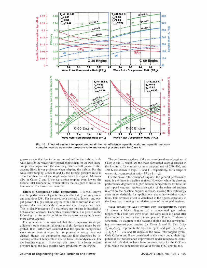
Effect of Compressor Inlet Temperature. It is well knownthat the performance of gas turbines is affected by varying ambi-ent conditions �58�. For instance, both thermal efficiency and out-put power of a gas turbine engine with a fixed turbine inlet tem-perature decrease when the compressor inlet temperature rises.This is disadvantageous if a stationary gas turbine is installed inhot-weather locations. Under this consideration, it is proved in thefollowing that for such conditions the wave-rotor-topping is evenmore advantageous.
For simulation, it is assumed that the compressor isentropicefficiency stays constant although a slight decrease might be ex-pected. It is furthermore assumed that the specific compressionwork stays constant since the compressor geometry does notchange. Hence, the compressor pressure ratio decreases by in-creasing ambient temperature due to basic thermodynamics. Forthe baseline engine it is obvious this results in a lower turbine
Fig. 10 Effect of ambient temperature-overall thesumption versus wave rotor pressure ratio and ov
pressure ratio and less specific work produced by the engine.
Journal of Engineering for Gas Turbines and Power
The performance values of the wave-rotor-enhanced engines ofCases A and B, which are the most considered cases discussed inthe literature, for compressor inlet temperatures of 250, 300, and350 K are shown in Figs. 10 and 11, respectively, for a range ofwave rotor compression ratios PRW=1,… ,2.
For the wave-rotor-enhanced engines, the general performancetrend is the same as baseline engines. However, while the absoluteperformance degrades at higher ambient temperatures for baselineand topped engines, performance gains of the enhanced enginesrelative to the baseline engines increase, making this technologyeven more desirable for applications under hot-weather condi-tions. This reversed effect is visualized in the figures especially inthe lower part showing the relative gains of the topped engines.
Wave Rotors for Gas Turbines with Recuperations. Figure12 shows a block diagram of a recuperated gas turbinetopped with a four-port wave rotor. The wave rotor is placed afterthe compressor and before the recuperator. Figure 13 shows aschematic T-s diagram of the baseline engine and the correspond-ing wave-rotor-topped engine for Cases A and B. Path 0-1b-2b
*-4b-5b-5b* represents the baseline cycle and path 0-1i-2i-2i
*-3i-4i-5i-5i
* �i=A and B� indicates the wave-rotor-topped cycles.Only Cases A and B are considered in this study due to their highpotential for performance improvement under recuperated condi-tions. All calculations have been presented only for the C-30 en-
al efficiency, specific work, and specific fuel con-ll pressure ratio for Case A
rmera
gine, while the conclusions are valid for the C-60 engine, too.
JANUARY 2006, Vol. 128 / 199
era
The analytical approach to analysis such wave-rotor-topped re-cuperated cycles has been introduced by the authors in previouswork �59� and is not stated here. Instead, Table 5 summarizes theobtained results and shows a comparison between performanceimprovements of the simple and recuperated engines for imple-mentations of both Cases A and B. It is seen from the table thatthe baseline engine �C-30 without the wave rotor� with recupera-tion has much higher efficiency �about twice� and lower SFC thanthose of the unrecuperated baseline engine due to the reduction of
Fig. 11 Effect of ambient temperature-overall thesumption versus wave rotor pressure ratio and ov
Fig. 12 Schematic of a recuperated gas turbine topped by a
four-port wave rotor
200 / Vol. 128, JANUARY 2006
heat addition in the combustion process, as expected. As ex-plained before, implementation of Case A into the baseline engineresults in a significant performance improvement of the unrecu-perated engine, however, the thermal efficiency and SFC improve-
l efficiency, specific work, and specific fuel con-ll pressure ratio for Case B
Fig. 13 Schematic T-s diagram for a recuperated baseline
rma
cycle and two wave-rotor-topped cycles
Transactions of the ASME
ments of the recuperated engine are much less than that of thespecific work. In Case B, however, the topped recuperated cyclehas higher performance compared to the unrecuperated engine andits thermal efficiency and SFC gains are even more than those ofCase A. Case B takes advantage of the fact that the temperaturedifference between the air and the gas entering the recuperator ofthe topped engine �Tt5B−Tt2B� is more than that of Case A�Tt5A−Tt2A�. This results in a higher recuperation effect for CaseB. The results clearly demonstrate the advantage of implementingCase A for unrecuperated engines and implementing Case B forrecuperated engines. The results also indicate that the recuperatorenhances thermal efficiency and SFC better, while the wave-rotoris mostly better for enhancing the specific work output. Therefore,substituting a recuperator with a wave rotor may be guided by apreference for high power output and reduced unit cost, consider-ing that a recuperator contributes about 25%–30% to the unit cost�11–13� and a wave rotor may be cheaper.
ConclusionFor the implementation of a wave rotor into two simple-cycle
microturbines C-30 and C-60, the present investigation predicts anattractive performance enhancement for both baseline engines.The smaller C-30 engine would benefit more from the wave-rotor-topping than the C-60 engine. The C-30 engine overall efficiencyand specific work may increase by up to 34% and for the C-60engine by up to 25%. Five different cases of implementing a waverotor into the existing baseline engines are investigated. Ideally,one of the three main components �compressor, combustor, orturbine� would remain unchanged when a wave rotor is imple-mented. However, compromises may be considered for tests orcost-effective prototype development, keeping two or even allthree main components unchanged. Case A, in which the baselinecompressor remains completely unchanged, appears to be themost beneficial case. However, the combustor works under higherpressure and with higher combustion end temperature. The turbinepressure ratio increases as well. Thus, an adaptation of the turbinewheel may be desired to utilize the obtained potential optimally.Other cases with unchanged overall pressure ratio �Cases B andC�, with unchanged combustion end temperature �Cases D and E�or unmodified turbine �Case D� are investigated as well. Case Bgives an increased turbine exit temperature and is therefore espe-cially attractive for external heat recovery applications or internalrecuperation, which would enhance the performance even more.Sacrificing some performance enhancement, the wave-rotorimplementation can yield other advantages like decreased turbineinlet temperature �Cases C and E�, reduced compressor pressureratio �Cases B, C, and D� or reduced turbine pressure ratio �CasesB and C�, which can reduce the gas turbine cost. Further, adding a
Table 5 Performance comparison between siwave-rotor-topping with a wave rotor pressure
wave rotor instead of a second compressor stage results in better
Journal of Engineering for Gas Turbines and Power
or similar performance enhancement and has many other advan-tages. While a second compressor stage alters the dynamic systemtremendously and always increases the combustion pressure, tur-bine inlet pressure and compressor work transmitted through theshaft, a wave-rotor implementation requires no or only minorchanges to the dynamic system of the gas turbine spool. It cankeep the combustion pressure the same, can even reduce the tur-bine inlet pressure or temperature and the transmitted shaft workfor the compressor. Furthermore, it is shown that the performancedegradation at higher temperatures is much less for the wave-rotor-topped engines than for the baseline engines, making thistechnology even more desirable for applications under hot-weather conditions. Finally, it is shown that the recuperator isbetter for improving overall thermal efficiency and specific fuelconsumption, while the wave-rotor-topping is better for increasingthe specific work output. Cost considerations may additionallyfavor the wave-rotor.
AcknowledgmentThe authors wish to acknowledge the cooperation of Capstone
Turbine Corporation, providing the baseline engine data. The as-sistance of A. Behinfar in sketching Figs. 1 and 3 is acknowl-edged.
References�1� Craig, P., 1997, “The Capstone Turbogenerator as an Alternative Power
Source” SAE Paper 970292.�2� Kang, Y., McKeirnan, R., 2003, “Annular Recuperator Development and Per-
formance Test for 200 kW Microturbine” ASME Paper GT-2003-38522.�3� Benini, E., Toffolo, A., and Lazzaretto, A., 2003, “Centrifugal Compressor of
A 100 KW Microturbine: Part 1-Experimental and Numerical Investigationson Overall Performance” ASME Paper GT2003-38152.
�4� Zauner, E., Chyou, Y. P., Walraven, F., and Althaus, R., 1993, “Gas TurbineTopping Stage Based on Energy Exchangers: Process and Performance”ASME Paper 93-GT-58.
�5� Rogers, C., 2003, “Some Effects of Size on the Performance of Small GasTurbine” ASME Paper GT2003-38027.
�6� Shi, J., Venkata, R., Vedula, J. H., Connie, E. B., Scott, S. O., Bertuccioli, L.,and Bombara, D. J., 2002, “Preliminary Design of Ceramic Components forthe ST5+ Advanced Microturbine Engine” ASME Paper GT-2002-30547.
�7� Walsh, C., An, C., Kapat, J. S., and Chow, L. C., 2002, “Feasibility of aHigh-Temperature Polymer-Derived-Ceramic Turbine Fabricated ThroughMicro-Stereolithography” ASME Paper GT-2002-30548.
�8� McDonald, C. F., 1996, “Heat Recovery Exchanger Technology for Very SmallGas Turbine” Journal of Turbo and Jet Engines, 13, pp. 239–261.
�9� Proeschel, R. A., 2002, “Proe 90TM Recuperator for Microturbine Applica-tions” ASME Paper GT-2002-30406.
�10� Carman, B. G., Kapat, J. S., Chow, L. C., and An, L., 2002, “Impact of aCeramic Microchannel Heat Exchanger on a Microturbine” ASME PaperGT2002-30544.
�11� McDonald, C. F., 2000, “Low Cost Recuperator Concept for MicroturbineApplications” ASME Paper GT2000-167.
�12� Utriainen, E., and Sunden, B., 2001, “A Comparison of Some Heat TransferSurfaces for Small Gas Turbine Recuperators” ASME Paper GT2001-0474.
le and recuperated engines and two cases oftio of 1.8, C-30 engine
mpra
�13� Maziasz, P. J., Pint, B. A., Swindeman, R. W., More, K. L., and Lara-Curzio,
JANUARY 2006, Vol. 128 / 201
E., 2003, “Selection, Development and Testing of Stainless Steel and Alloysfor High-Temperature Recuperator Applications” ASME Paper GT2003-38762.
�14� Wilson, J. and Paxson, D. E., 1993, “Jet Engine Performance EnhancementThrough Use of a Wave-Rotor Topping Cycle” NASA TM-4486.
�15� Fatsis A., and Ribaud Y., 1999, “Thermodynamic Analysis of Gas TurbinesTopped with Wave Rotors” Aerosp. Sci. Technol., 3, No. 5, pp. 293–299.
�16� Akbari, P., and Müller, N., 2003, “Performance Improvement of Small GasTurbines Through Use of Wave Rotor Topping Cycles” ASME Paper GT2003-38772.
�17� Akbari, P., and Müller, N., 2003, “Performance Investigation of Small GasTurbine Engines Topped with Wave Rotors” AIAA Pap. 2003-4414.
�18� Meyer, A., 1947, “Recent Developments in Gas Turbines” Chin. J. Mech.Eng., 69, No. 4, pp. 273–277.
�19� Real, R., 1946, “The 3000 kW Gas Turbine Locomotive Unit” Brown BoveriRev., 33, No. 10, pp. 270-271.
�20� Meyer, A., 1947, “Swiss Develop New Gas Turbine Units” Electr. World, 127,pp. 38-40.
�21� Azoury P. H., 1992, Engineering Applications of Unsteady Fluid Flow, JohnWiley and Sons, New York.
�22� Rose, P. H., 1979, “Potential Applications of Wave Machinery to Energy andChemical Processes” Proceedings of the 12th International Symposium onShock Tubes and Waves, pp. 3–30.
�23� Seippel, C., 1940, Swiss Patent No. 225426.�24� Seippel, C., 1942, Swiss Patent No. 229280.�25� Seippel, C., 1946, “Pressure Exchanger” US Patent 2399394.�26� Seippel, C., 1949, “Gas Turbine Installation” US Patent 2461186.�27� Taussig, R. T., Hertzberg, A., 1984, “Wave Rotors for Turbomachinery” Winter
Annual Meeting of the ASME, edited by Sladky, J. F., Machinery for DirectFluid-Fluid Energy Exchange, AD-07, pp. 1–7.
�28� Zehnder, G., Mayer, A. and Mathews, L., 1989, “The Free Running Com-prex®” SAE Paper 890452.
�29� Mayer, A., Oda, J., Kato, K., Haase, W. and Fried, R., 1989, “ExtrudedCeramic-A New Technology for the Comprex® Rotor” SAE Paper 890453.
�30� Hiereth, H., 1989, “Car Tests With a Free-Running Pressure-Wave Charger-AStudy for an Advanced Supercharging System” SAE Paper 890 453.
�31� Azoury, P. H., 1965-66, “An Introduction to the Dynamic Pressure Exchanger”Proc. Inst. Mech. Eng., 180, Part 1, No. 18, pp. 451–480.
�32� Guzzella, L., Wenger, U., and Martin, R., 2000, “IC-Engine Downsizing andPressure-Wave Supercharging for Fuel Economy” SAE Paper 2000-01-1019.
�33� Shreeve, R. P., Mathur, A., 1985, Proceeding ONR/NAVAIR Wave Rotor Re-search and Technology Workshop, Report NPS-67-85-008, Naval PostgraduateSchool, Monterey, CA.
�34� Paxson, D. E., 1992, “A General Numerical Model for Wave-Rotor Analysis”NASA TM-105740.
�35� Paxson, D. E., 1996, “Numerical Simulation of Dynamic Wave Rotor Perfor-mance” J. Propul. Power, 12, No. 5, pp. 949-957.
�36� Welch, G. E., Jones, S. M., and Paxson, D. E., 1997, “Wave Rotor-EnhancedGas Turbine Engines” J. Eng. Gas Turbines Power, 119, No. 2, pp. 469–477.
�37� Welch, G. E., 1997, “Macroscopic Balance Model for Wave Rotors” J. Propul.Power, 13, No. 4, pp. 508–516.
�38� Welch, G. E., 1997, “Two-Dimensional Computational Model for Wave RotorFlow Dynamics” J. Eng. Gas Turbines Power, 119, No. 4, pp. 978–985.
202 / Vol. 128, JANUARY 2006
�39� Wilson, J., and Paxson, D. E., 1996, “Wave Rotor Optimization for Gas Tur-bine Topping Cycles” J. Propul. Power, 12, No. 4, pp. 778–785. See SAEPaper 951411, and NASA TM 106951.
�40� Welch, G. E., 2000, “Overview of Wave-Rotor Technology for Gas TurbineEngine Topping Cycles” Novel Aero Propulsion Systems International Sympo-sium, The Institution of Mechanical Engineers, pp. 2–17.
�41� Wilson, J., 1997, “Design of NASA Lewis 4-Port Wave Rotor Experiment”AIAA Pap. 97-3139. Also NASA CR-202351.
�42� Wilson J., and Fronek, D., 1993, “Initial Results from the NASA-Lewis WaveRotor Experiment” AIAA Pap. 93-2521. Also NASA TM-106148.
�43� Wilson, J., 1997, “An Experiment on Losses in a Three Port Wave-Rotor”NASA CR-198508.
�44� Wilson, J., 1998, “An Experimental Determination of Loses in a Three-PortWave Rotor” J. Eng. Gas Turbines Power, 120, pp. 833–842. Also ASMEPaper 96- GT-117, and NASA CR-198456.
�45� Paxson, D. E., 1993, “A Comparison Between Numerically Modeled and Ex-perimentally Measured Loss Mechanisms in Wave Rotors” AIAA Pap. 93-2522.
�46� Paxson, D. E., 1995, “Comparison Between Numerically Modeled and Experi-mentally Measured Wave-Rotor Loss Mechanism” J. Propul. Power, 11, No.5, pp. 908–914. Also NASA TM-106279.
�47� Paxson D. E., and Wilson, J., 1995, “Recent Improvements to and Validationof the One Dimensional NASA Wave Rotor Model” NASA TM-106913.
�48� Paxson, D. E., and Nalim, M. R., 1999, “Modified Through-Flow Wave-RotorCycle with Combustor Bypass Ducts” J. Propul. Power, 15, No. 3, pp. 462-467. Also AIAA Paper 97-3140, and NASA TM-206971.
�49� Nalim, M. R., and Paxson, D. E., 1999, “Method and Apparatus for Cold-GasReinjection in Through-Flow and Reverse-Flow Wave Rotors” US Patent5,894,719.
�50� Jones, S. M., and Welch, G. E., 1996, “Performance Benefits for Wave Rotor-Topped Gas Turbine Engines” ASME Paper 96-GT-075.
�51� Weber, H. E., 1986, “Shock-Expansion Wave Engines: New Directions forPower Production” ASME Paper 86-GT-62.
�52� Weber, H. E., 1995, Shock Wave Engine Design, John Wiley and Sons, NewYork.
�53� Akbari, P., Kharazi, A. A., and Müller, N., 2003, “Utilizing Wave Rotor Tech-nology to Enhance the Turbo Compression in Power and Refrigeration Cycles”ASME Paper IMECE2003-44222.
�54� Gyarmathy, G., 1983, “How Does the Comprex Pressure-Wave SuperchargerWork?” SAE Paper 830234.
�55� Kentfield, J. A. C., 1993, Nonsteady, One-Dimensional, Internal, CompressibleFlows, Oxford University Press, Oxford.
�56� Taussig, R. T., 1984, “Wave Rotor Turbofan Engines for Aircraft” WinterAnnual Meeting of the ASME, edited by Sladky, J. F., Machinery for DirectFluid-Fluid Energy Exchange, AD-07, pp. 9–45.
�57� Welch, G. E., 1996, “Two-Dimensional Computational Model for Wave RotorFlow Dynamics” ASME Paper 96-GT-550.
�58� El Hadik, A. A., 1990, “The Impact of Atmospheric Conditions on Gas Tur-bine Performance” J. Eng. Gas Turbines Power, 112, No. 4, pp. 590–595.
�59� Akbari, P., Müller, N., and Nalim, M. R., 2004, “Performance Improvement ofRecuperated and Unrecuperated Microturbines Using Wave Rotor Machines,”2004 ASME-ICED Spring Technical Conference, Japan.