Page 1
Performance Enhancing of Galloping-basedPiezoelectric Energy Harvesting by Exploiting 1:1Internal Resonance of Magnetically CoupledOscillatorsWan Sun
Jiangsu UniversityCanzhi Guo
Jiangsu UniversityGuanggui Cheng
Jiangsu UniversityShangwen He
Zhengzhou Universityzhaorui yang ( [email protected] )
Zhengzhou UniversityJianning Ding
Jiangsu University
Research Article
Keywords: Internal resonance, Multiple time scale, Frequency synchronization, Nonlinear force coupling,Wind energy harvesting
Posted Date: November 3rd, 2021
DOI: https://doi.org/10.21203/rs.3.rs-1022013/v1
License: This work is licensed under a Creative Commons Attribution 4.0 International License. Read Full License
Page 2
1
Performance enhancing of galloping-based piezoelectric energy 1
harvesting by exploiting 1:1 internal resonance of magnetically 2
coupled oscillators 3
Wan Suna,b, Canzhi Guoa,b, Guanggui Chenga,b, Shangwen He b, Zhaorui Yangb*, Jianning Ding a,b* 4
a Institute of Intelligent Flexible Mechatronics, Jiangsu University, Zhenjiang 212013, P.R. China 5
b Jiangsu Collaborative Innovation Center of Photovoltaic Science and Engineering, Changzhou 6
University, Changzhou 213164, P.R. China 7
c School of Mechanics and Safety Engineering, Zhengzhou University, Zhengzhou 450001, P.R. China 8
9
10
11
*Corresponding Author 12
E-mail address: 13
[email protected] (Zhaorui Yang) 14
[email protected] (Jianning Ding) 15
16
Page 3
2
Abstract 1
In this study, we introduced 1:1 internal resonance in a magnetically coupled 2-degree-of-freedom 2
(2-DOF) galloping-based piezoelectric energy harvester to improve the energy harvesting efficiency. 3
The governing equations for the proposed magnetically coupled aero-electro-mechanical system 4
considering the effect of oscillating wake are established using the extended Hamilton principle, and the 5
method of multiple scale is exploited to obtain approximate analytical solutions. Parameter sweeping 6
numerical calculation is conducted to validate the analytical prediction through comparing with 7
analytical solutions, and the results show a good matching between them. In addition, we investigated 8
the systematic dynamic behaviors under a pure oscillating wake induced 1:1 internal response. Typical 9
nonlinear characteristics such as jump, hysteresis, frequency synchronization under varying design 10
parameters appear in the present system. Especially, cusp bifurcation and synchronization regime of 11
oscillating wake coupled nonlinear oscillator in w plane and w plan. With an adoption of 12
magnetic force, chaos happens as the gap distance decreases smaller than 5 mm, and a frequency lock-in 13
phenomenon can be strengthened through adjusting the magnet distance. In the perspective of output 14
performance, both of the voltage and power output results shows that the exploiting of 1:1 internal 15
resonance can significantly improve the output performance under a suitable magnet distance. 16
Keyword: Internal resonance; Multiple time scale; Frequency synchronization; Nonlinear force 17
coupling; Wind energy harvesting. 18
19
Page 4
3
1 Introduction 1
With the dramatic increasing of energy consumption due to the rapid industrial development, a 2
series of environmental pollution problems have been continually arisen over the past few decades. It is 3
anticipated that the development of renewable and sustainable energy is the trend of human development 4
in the future, and this viewpoint is becoming the consensus all over the world. Energy harvesting from 5
the surrounding environment as an alternative of renewable energy has been receiving increasing interest 6
in recent few decades. In particular, the recent rapid developments of wireless sensor networks 7
necessitate some new demands on self-powering technologies such as portability, small-scale, high 8
efficiency, environmental adaptability, which promotes numerous researchers devoting their efforts in 9
developing various energy harvesting technologies. 10
In accordance with the operation environment of the sensor nodes and electric devices, various 11
forms of wasted energy sources such as wind [1], mechanical [2, 3], thermal, solar, and chemical sources 12
can be selected and converted into electric energy for the electric consumption devices. Wind energy, as 13
one of the most common wasted energy sources, which has abundant free utilization value. A large 14
amount usage of wind energy has been applied to the traditional rotating wind turbine [4, 5] for 15
commercial power supplies because of its high output and high efficiency in wind energy conversion. 16
On the other hands, wind turbine is difficult to meet the requirements of self-power supply of small-17
scale wireless sensors that need a compact structural integration of the power supply components and 18
target small-scale electric device. Therefore, the instinct shortage of the wind turbine applying in small-19
scale electric devices accelerated the development of the studies on compact wind energy harvesting 20
Page 5
4
system based on flow induced vibrations such as vortex-induced vibration (VIV), galloping, flutter, and 1
wake galloping. Among them, galloping phenomenon is a representative flow-induced vibration, which 2
happens when the structural system loses its stability. The galloping phenomenon is broadly applied in a 3
small-scale wind energy harvesting system because it usually exhibits a large oscillation amplitude and 4
wide operating wind velocity range compared to VIV, flutter and wake galloping [6-8]. 5
The wind energy can be converted into electric energy through three typical transduction 6
mechanisms of electromagnetic, electrostatic, and piezoelectric. Among them, the piezoelectric 7
mechanism is the most popular owing to its high energy density and easiness of application [8-10]. In 8
the last decade, a variety of piezoelectric wind energy harvesters (PEH) have been studied from the basis 9
mechanisms of flow induced vibration to the technologies of improving energy conversion efficiency 10
[11-15]. Among various aerodynamic phenomenon-based wind energy harvesters, galloping-based 11
piezoelectric wind energy harvester (GPEH) exhibits an excellent performance compared to the others 12
because of its larger amplitude response and wider operational wind range. A general GPEH is 13
composed of a cantilever beam attached with piezo patch and a cross-section asymmetric bluff body 14
fixed on its free end. To further improve energy harvesting efficiency and reduce the critical wind speed, 15
some researchers have been devoting their efforts on optimizing the cross-section of bluff body [16-21], 16
exerting synergy effect by combining aerodynamic phenomena (VIV, galloping) [22-25] and increasing 17
the degrees of freedom (DOF) [26, 27]. Lan et al. [26] proposed lumped parameter models for two 18
structural configurations with different bluff bodies under aerodynamic force. They analytically and 19
Page 6
5
numerically compared the output performances between the proposed configurations which shows that 1
the second configuration with the wind flow loaded on the outer bluff body can easily and remarkably 2
reduce the critical wind speed and improve the output power. In addition, Hu et al. [7] recently proposed 3
a comb-like beam (CombBeam) based GPEH, which consists of several parasitic beams mounted on a 4
conventional cantilever beam. This structure is regarded as a multiple-degree-of-freedom (MDOF) 5
system. They showed that the MDOF CombBeam-based GPEH was superior to the conventional beam 6
GPEH in reducing the cut-in wind speed from 2.24 m/s to 1.96 m/s and enhancing the power for about 7
171.2% with an optimal resistance under a specific wind speed of 3 m/s. Starting from such kinds of 8
linear 2-DOF GPEH, an exploiting of external nonlinear force in a flow induced vibration energy 9
harvester was also considered in some works to further enhance the energy harvesting performance. 10
Wang et al. [28] proposed a double-beam piezo–magneto–elastic nonlinear wind energy harvester, in 11
which two piezoelectric cantilever beams attached to prism-like bluff bodies employing repulsive 12
magnets were fixed vertically and oriented to face each other. Most recently, Sun et al. [6] investigated a 13
magnetically coupled GPEH in a tandem configuration to improve the energetic performance, which 14
consists of two elastic structures with two bluff bodies and a pair of repulsive magnets installed for the 15
generation of mutual interaction between them. This work showed that a maximum overall average 16
output power of 8.09 mW and power improvement rate of 65% were obtained compared to the case 17
without magnetic interaction under an optimal magnetic gap distance. 18
However, to the best of our knowledge, few study has reported on consideration of the effects of 19
Page 7
6
the natural frequency ratio between the oscillators to the overall output performance in a two or multiple 1
DOF GPEH. Up till now, some systematic studies on the internal resonance have been carried out on a 2
general 2-DOF PEH in the previous works. In these previous works [29-32], the dynamical behaviors 3
show dramatical changes when one of the natural frequencies is close to the other where internal 4
resonance happens. Internal resonance has been extensively reported in external forced vibration energy 5
harvesting system for an output performance enhancement [33, 34], which usually appears when the 6
ratio between two natural frequencies of a given system is close to an integer and various interesting 7
phenomena such as frequency or (and) lock-in (synchronization), hysteresis, chaotic behaviors can be 8
resulted in. Inspired by these work on internal resonance in a 2-DOF PEH, this study tried to exploit 1:1 9
internal resonance in a development of magnetically coupled galloping-based piezoelectric energy 10
harvester (MCR- GPEH) for a significant output performance improvement. 11
This study proposed a lumped parameter model for the MCR-GPEH considering the effect of 12
oscillating wake using Hamilton principle, and a series of comprehensive parametric studies have been 13
analytically and numerically conducted to predict the evaluation of the symmetric dynamic behavior 14
when the internal resonance happens. This work provides a general framework and design guidance for 15
a high efficiency wind energy harvester by exploiting 1:1 internal resonance through controlling the 16
distance. Both of the numerical and analytical results showed that 1:1 internal resonance wind energy 17
harvesting system is expected to be a promising alternative in the development of high-efficiency 18
galloping-based wind energy harvesting system. 19
Page 8
7
2 Dynamic modeling 1
2.1 Conceptual description 2
3
Fig. 1 Schematic of the magnetically coupled 2-DOF galloping-based piezoelectric energy harvester. 4
5
Conventional piezoelectric wind energy harvester based on galloping or VIV aerodynamic 6
phenomenon is generally designed with a single cantilever beam and a bluff body fixed on its free end. 7
The wind energy can be converted into structural vibration energy, and then into electric energy through 8
the piezoelectric transducer, which has been thoroughly investigated in various aspects such as 9
fundamental theory construction, novel structure design and aerodynamic energy conversion mechanism 10
in the previous studies. 11
In this study, we proposed a magnetically coupled 2-DOF galloping-based piezoelectric energy 12
harvester to increase the energy harvesting efficiency through double-steps energy extraction from the 13
incoming wind flow using the tandem arrangement of the bluff bodies as shown in Fig. 1. The proposed 14
structure is configured with two presumed arbitrary bluff bodies and individually connected to a fixture 15
using elastic component. Considering the merits of galloping phenomenon in wind energy harvesting as 16
Page 9
8
introduced in Introduction section, the cross-section shape of the bluff bodies is designed as circular 1
asymmetric shape for aerodynamic instability. The primary bluff body is arranged in the front of the 2
secondary bluff body with a tandem configuration along the wind incoming direction. The wind flow 3
passing the primary bluff body generates wake flow that applies to the secondary bluff body and further 4
give rise to the variation of its dynamic behaviors. However, the oscillation of the secondary bluff body 5
has a negligible influence to the primary bluff body due to the directionality of the wake flow as 6
investigated in [35]. In this study, we exploited a pair of mutually repelling magnets, which are attached 7
to the inner side of each bluff body to strengthen the coupling effect of the dynamic behaviors of the two 8
bluff bodies to achieve synergistic effect. 9
This study focuses on the investigation of the overall output performance of the two individual 10
elastic structures under various natural frequency difference. The nonlinear characteristics induced by 11
the wind flow and magnet force lead to various nonlinear dynamic behaviors such as jump phenomenon, 12
limit cycle, frequency synchronization and catastrophe bifurcation. The variation of the natural 13
frequency difference between two weakly coupled mass-spring-damper system results in 14
synchronization and internal resonance which is beneficial to improve the wind energy harvesting 15
performance. 16
2.2 Governing equations 17
In this section, a mathematical modeling of the proposed magnetically coupled 2-DOF system is 18
derived to predict the dynamic behaviors and output voltage performance. The proposed system consists 19
Page 10
9
of two discrete mass-spring-damper components which are coupled with weak nonlinear magnetic force, 1
the governing equations can be formulated using the expended Hamilton’s principle as follows: 2
2
1
d 0t
t t nct
T W t , (1) 3
where t represents time, tT and t
represent the variations of the total kinetic and potential energy 4
contained in this system, respectively, and nc
W is the virtual work done by the non-conservative forces. 5
The kinetic energy in the proposed system includes the translational and rotational kinetic energies of 6
the outer and inner bluff bodies. Thus, the total kinetic energy tT in the present system is given by 7
2 21 21 2
1 1
2 2tT m y m y & & , (2) 8
where the over-dot of a symbol denotes a derivative with respect to time t ; 1m and 2m denote the total 9
masses of the bluff bodies (primary, secondary) and the corresponding attached permanent magnets, 10
respectively; 1y and 2y denote the displacement of the primary and secondary bluff bodies. 11
The potential energy of the proposed system includes several components such as the electrical, 12
electromechanical, mechanical, and magnetic potential energy. Subsequently, the total potential energy 13
t of the proposed system is expressed as follows: 14
2 2 2 21 1 1 2 1 1 2 2 1 1 1 2 2 2
1 1 1 1( ) ( ) ( ) ( )
2 2 2 2mag p p et eU k y k y c t c t t y t y & & & & , (3) 15
where 1k and 2k represent the spring constants of the primary and secondary spring; 1pc and 2p
c 16
represent the capacitance of the primary and secondary piezo components; 1e and 2e
represent the 17
piezoelectric coupling coefficients; 1& and 2& represent the flux linkage of the equivalent circuit of the 18
Page 11
10
piezoelectric components; magU represents the potential energy from the magnetic field generated by 1
the two repulsive magnets, which can be described by the dipole–dipole model due to the small size 2
compared to the bluff body [36]. 3
03
24
B BAmag A
BA
U
m rm
r
03 5
2 2
31
4B BA
B BA A
BA BA
m rm r m
r r, (4) 4
where 0 is the vacuum permeability; BAr is the vector from the center of the magnet A to the center of 5
the magnet B; and Am and B
m are the magnetic moment vectors of the outer and inner magnets, 6
respectively. For a permanent magnet, the magnitude of the magnetization vector can be evaluated using 7
the magnet’s residual flux density rB , that is, 0/
rm B . Under a series of mathematical manipulation, 8
the magnetic potential energy can be expressed as 9
1.5 2.52 2 2 21 1 01 2 12
22 212( , ) 3
4mag m m m
m m v vU y y y D D y D
, with 12 1 2y y y , (5) 10
referring to [6]. where 1m and 2m are the magnitudes of magnetization vectors, and 1v and 2v are the 11
volumes of the primary and secondary magnets; and mD is the minimum gap distance between the 12
center points of the two magnets. Take the derivative with respect to 12y on the magnetic potential 13
energy and then expand the resulting equation in a Taylor series at 12 0y , the magnetic force can be 14
obtained as 15
31 12 3 12
magF Y Y , with 0 0
1 35 7
12 45,
4 4A B A B A B A B
m m
m m v v m m v v
D D
. (6) 16
The virtual work done by the non-conservative forces is given by 17
Page 12
11
g1 1 2 1 1 2 2 2 1 1 1 1
2 2 1 2 2 2 2 2
2 1
2 ( ) ( ) / ( ) ( ) /
w w
nc g
L L
W F y F y y y y y y c y y
c y y t t R t t R
& & &
& &&, (7) 1
where 1L
R and 2L
R represent the load resistances for the primary and secondary external circuit, 2
respectively; 1c and 2c represent the damping constants; w
i denote the wake force coefficients, and we 3
assumed they are both equal to w ; 1g
F and 2gF are the aerodynamic transverse force acting on the 4
bluff bodies, which can be expressed as [23] 5
2igi i i gF nU C with a0.5
i in DH , (8) 6
where the indices i =1, 2 represent the corresponding symbols for primary and secondary bluff bodies, 7
respectively. a represents the air density; iH and
iU are the height of the bluff bodies and the wind 8
velocity applied to each bluff bodies. gi
C represents the dimensionless coefficients of the aerodynamic 9
transverse force, which is a function of attack angle according to the assumption of quasi-steady state of 10
the bluff bodies in wind flow field referring to the previous studies [19, 37]. gi
C is the inherent 11
characteristics related to the cross-section shape of the bluff body and Renolds number, which can be 12
obtained through series expansion of the transverse aerodynamic force at different rotation angles of the 13
bluff body. It can be expressed as 35
1 53( ) ,igi i i ii i iAC A A L with /
i i iy U & , where 1i
A , 3iA , 14
5iA are the aerodynamic coefficients. In this study, a third-order expansion is adopted to describe the 15
nonlinear dynamic behaviors resulted from the aerodynamic force. 16
Subsequently, we performed several manipulations using variational calculus to Eqs. (2), (3) and 17
(7), then substituted the resultants into Eq. (1) to gather the coefficients of 1y , 2y , 1( )t and 2 ( )t . 18
Page 13
12
Furthermore, we conducted a normalization manipulation for a calculation convenience, thus a set of 1
governing equations can be obtained as 2
31 1 1 3 1 1 1 1 g11 1 1 1 1 2 2 22 ( ) ( ) w
e eFy y y y yy Vyy & % %&& & , (9a) 3
32 1 1 3 1 2 2 22 2 2 2 2 22 1 g22 ( ) ( ) w
e ey y y y y yy yV F % %& % %&& & , (9b) 4
1 1 1 1 1 0V V y & %& , (9c) 5
2 2 2 2 2 0V V y & %& , (9d) 6
where the definitions of the normalized parameters in Eqs. (9) are listed in Table 1. The set of governing 7
equations given in Eq. (9) indicates that the two primary and secondary oscillators are mechanically 8
coupled to each other through a nonlinear magnetic force. Additionally, the oscillating aerodynamic 9
wake force generated by the adjacent bluff body during oscillation is considered to avoid the loss of 10
generality of the mathematical modeling although it has a tiny disturbance to the dynamic behaviors of 11
bluff body compared to the magnetic force. It should be noted that the oscillating wake force acting to 12
the bluff bodies is not equal due to the unilaterality of the incoming wind flow. Accordingly, an order 13
selection considering the wake force scale should be conducted in finding analytical solution using 14
perturbation method. 15
16
Page 14
13
Table 1 Normalized parameters used in the governing equations, where 1,2i denotes the primary and 1
secondary oscillators, respectively. 2
Definition Parameters
Undamped natural frequencies = /i i i
k m
Damping ratios / 2i i i i
c m k
Mass normalized electromechanical coupling coefficients /ei ei i
m
Normalized wake coupling coefficients = /w w
i i im %
Normalized magnetic force coefficients for primary oscillator 1 1 1 3 3 1/ , /m m
Normalized magnetic force coefficients for secondary oscillator 1 1 2 3 3 2/ , /m m % %
Capacitance normalized electromechanical coupling coefficients /i ei pi
C %
Equivalent impedances 1/i Li pi
R C
3
2.3 Analytical solutions based on method of multiple scale 4
In an attempt to understand the nonlinear dynamic behaviors of the present system, especially the 5
internal resonance between the individual oscillator, the perturbation method of multiple scale is utilized 6
to obtain the approximate analytical solutions for Eq. (9). The time dependence can be expanded into 7
two time scales in the form 0T t (fast time scale) and
1T t (slow time scale), respectively, where 8
is a scaling parameter. The new time derivatives with respect to t can be expressed as: 9
2
2 2 20 1 0 0 12
d d, 2
d dD D O D D D O
t t , (10) 10
where n
n
DT
and 2O denotes the terms higher than the second power of . The asymptotic 11
Page 15
14
series solutions are expanded up to the first order, such that 1
01 0 1 1 0 1 1 0 10 1
02 0 1 2 0 1 2 0 10 1
01 0 1 1 0 1 1 0 10 1
02 0 1 2 0 1 2 0 10 1
, , , ,
, , , ,
, , , ,
, , , ,
y T T y T T y T T
y T T y T T y T T
v T T v T T v T T
v T T v T T v T T
(11) 2
where the symbols of 0 and
1 represent the 0 and 1 order solution for the dynamic responses 3
of the primary and secondary oscillators. The oscillators in the present system are assumed to be weakly 4
coupled by the external magnetic force and oscillating wake force. An ordering for the terms in Eq. (9) 5
can be determined by scaling the viscous damping, magnetic coupling, electromechanical coupling, and 6
aerodynamic force in the same order. In other words, the scaled relevant coefficients or terms can be 7
expressed as 8
1 1 2 2 1 1 3 3 1 1
23 3 1 1 2 2 g1 g1 g2 g2.
, , , , ,
, = , = , = , =w w w wF F F F
% %
% % % % % % % %% % (12) 9
It should be noted that the oscillating wake coupling coefficient generated by the secondary oscillator is 10
defined to higher order of 2 considering the fact that the effect of the wake generated from the 11
secondary oscillator to the primary bluff body is much weaker than that from the primary oscillator to 12
the secondary oscillator generated. Substituting the scaled terms into Eq. (10) and expanding the 13
governing equations in terms of Eq. (10) and (12), we can obtain the ordered equations after collecting 14
the coefficients of 0 and 1 , which yields the following results: 15
0 order equations: 16
Page 16
15
2
21 1 12 0 0
0
0y yT
, (13) 1
2
22 2 22 0 0
0
0y yT
, (14) 2
0
1 10 0 01
1
0
10p e
L
c v y vT T R
, (15) 3
0
2 20 0 02
2
0
10p p e
L
c v c y vT T R
. (16) 4
1 order equations: 5
2 22 22
1 1 1 1 1 1 3 1 2 3 1 2 12 1 1 0 0 0 0 0 00 0 0 1
3
3 31 131 1 11 1 1 1 1 1 2 3 1 3 2 1 10 0 0 0 0 0 0
0 1 0
2 3 3
A
2
A
y y y y y y y yT T T T
nnU y y y y y y v
T U T
, (17) 6
2 22 22
2 2 2 2 2 2 3 1 2 3 1 2 22 1 1 0 0 0 0 0 00 0 0 1
3
3 32 232 2 21 2 2 3 2 2 2 1 1 1 1 1 2 3 10 0 0 0 0 0 0 0
0 2 0 0
2 3 3 2
A A w
y y y y y y y yT T T T
nn U y y y v y y y y
T U T T
% %
%% % % %
,(18) 7
1 1 1 1 11 1 1 0 00 0 1 1 1
1p e p e
L
c v y v c v yT T R T T
, (19) 8
2 2 2 2 21 1 1 0 00 0 2 1 1
1p p e p p e
L
c v c y v c v c yT T R T T
. (20) 9
The solutions of the zeroth-order Eqs. (13)-(16) can be written as: 10
1 0
1 1 10ei T
ccy A T , (21) 11
Page 17
16
2 0
2 1 10ei T
ccy B T , (22) 1
01 0
1
1 0
1 1 1 1 1 1 1 11 1 11
1 1 1 1
e( )e
1 1- epL
TTRe L e L
T
L p L p
ic
i
i A T R i A T Rv E T
iR c iR c
, (23) 2
00
2
2 0
2
1 1 2 2 1
2
1 22 2 11
2 22
2 e( )e
1 1- epL
TTRe L e L
T
L p L p
ic
i
i B T R i B T Rv E T
iR c iR c
. (24) 3
where cc denotes the complex conjugate of the preceding term. 1A and 1B denote the unknown 4
complex-valued functions for primary and secondary oscillators, respectively. The over-bar denotes the 5
complex conjugate. Substituting the zeroth-order solutions into the right hand side of the first order 6
equations (17-20) and expanding the equations, it can be observed that frequency modes with frequency 7
ratio of 1:1 are coupled via the oscillating wake force and the linear terms of magnetic force. 8
Additionally, it also can be observed that the frequency modes with frequency ratio of 1:3 are coupled 9
via cubic nonlinearities of the magnetic force. In this study, the 1:1 internal resonance plays a decisive 10
role in the improvement of dynamic behaviors and the output performance for the present system 11
referring to the results of a preliminary numerical analysis. After eliminating the undesired non-secular 12
terms and collecting coefficients of harmonics, it can be obtained as follows: 13
1 0 2 0
22
1 1 1 1 22 1 10
i T i Ty y Q e Q e cc NST
T
, with (25) 14
2 321 13 1 1 1 1 1 1 1 1 1 1
1 1 1 1 3 1 1 1 1
1 1 1
21 1 1 1 1 11 1 1 1 3 1 1 1 1 1 1 1 1 1 1
1
33
1
d2 6 2
dT
e e L
L p
in A A T A T i A T RQ A T A T A T
U iR c
i A T inU A A T A T B T B T i A T
, 15
2
2 3 1 1 1 1 1 1 3 1 1 1 1 1 1 16 3Q A T A T B T B T B T B T . 16
Page 18
17
1
1 0 2 0
22
2 2 2 3 42 1 10
e eT i i Ty y Q Q cc NST
T
, with (26) 2
2
3 3 1 1 1 1 3 1 1 1 1 1 1 1 1 1 1 1 13 6w
Q A T A T A T B T B T i A T A T , 3
2 32 23 1 1 2 1 1 2
4 3 1 1 1 1 1 1 2 2 1 1 1 1 2
2 1
2 2 2 1 1 2
3 1 1 1 1 2 2 21 1 1 2 1 1 1
2 2
d3 6 2 2
d
31
e e p L
L p
in A B T B TQ A T A T B T i B T i B T
U T
i B T c RB T B T in U A B T B T
iR c
%
% %
. 4
where NST stands for the terms that do not produce secular terms. Then, it is necessary to introduce the 5
1:1 internal resonance condition as 6
2 1 1 2, , (27) 7
where is the internal resonance detuning parameter, which represents the closeness of the two natural 8
frequencies of the primary and secondary oscillators. Substituting 2 and 1 in Eq. (27) into Eqs. (25)-9
(26) and after a mathematical manipulation, the simplified equations can be expressed as 10
1 01
22
1 1 1 1 22 1 10
i Ti Ty y Q Q e e cc NST
T
, (28) 11
2 01
22
2 2 2 3 42 1 10
i Ti Ty y Q Q e e cc NST
T
. (29) 12
Eliminating the terms that lead to secular terms in the above equations, and expressing the complex-13
valued function in the polar form 14
Page 19
18
1 1
11 1
e
2
i Ta T
A T
, 2 1
11 1
e
2
i Tb T
B T
, (30) 1
where a and b represent the unknown amplitude for the primary and secondary oscillators; 1 and 2 2
represent the phase of the corresponding dynamic responses. Next, separating the real and imaginary 3
parts in Eqs. (28)-(29) yields the modulation equations as 4
2 2 2 2 3 31 3 3 1 1 1 11 1 1 1 1 1 12 1 13 1
1 1 1
sin( ) 6 3 4 4 A 8 4 3 Ad
d 8
U b a b a U n U U E a na
T U
, (31) 5
2 2 2 311 3 3 1 3 3 11
1 1
4 3 6 4 6 3 4 cos( )d
d 8
a E a b a b b b
T a
, (32) 6
2 2 3 3 22 3 3 1 2 1 2 2 23 2 2 2 21 2 2 2
1 2 2
22sin( ) 3 6 4 4 cos( ) 3 A 4 A 8d
d 8
4
waU a b EU a b n U n U bb
T U
% %,(33) 7
3 2 2 23 3 1 1 3 3 21 12
1 2
3 6 4 cos( ) 4 sin( ) 6 3 4 4d
d 8
wa ab a a b a b E
T b
% % % % % %, with (34) 8
1 2 1T ,
2 21 1 1
11 2 2 21 1 1
e e p L
L p
c RE
R c
1 1 1
12 2 2 21 1 1e e L
L p
RE
R c
, 9
2 22 2 2
21 2 2 22 2 1
e e p L
L p
c RE
R c
2 2 2
22 2 2 22 2 1e e L
L p
RE
R c
. 10
The time derivatives of 1 and 2 in Eq. (32) and (34) can be vanished in terms of the relationship of 11
2 1 , where the primer means the time derivation of 1T , and thus the modulation equations 12
with 4-dimensional phase space ( 1 2, , ,a b ) can be reduced to a 3-dimensional phase space ( , ,a b ). 13
Additionally, the steady-state responses can be determined by setting the time derivatives in the 14
Page 20
19
modulation equations equal to zero. The resulted equations are a set of transcendental equations which 1
are difficult to be solved by an analytical method, however, it is fairly straightforward to be solved 2
numerically for semi-analytical solutions. Subsequently, we can obtain the output voltage generated by 3
the piezoelectric element using Eqs. (23) and (24), where homogeneous and non-homogeneous solutions 4
are contained in them. It is known that the homogeneous solutions would converge to zero on account of 5
the electric energy dissipation in the external resistor along the time. Consequently, we can find the 6
output voltage amplitude through the non-homogeneous terms, and the resultants can be expressed with 7
a function of the amplitude of the corresponding oscillators as 8
1 11 2 2 2
1 1
| |1
e L
L p
RV a
R c
, 2
2 2 222
2
2
| |1
e L
L p
RV b
R c
. (35) 9
Subsequently, the output power can be described as 10
2 2
21 11 2 2 2
1 1
| |1
e L
L p
RP a
R c
, 2 2
22 22 2 2 2
2 2 1e L
L p
RP b
R c
. (36) 11
According to the expressions of output voltage and power, we can compare the energy harvesting 12
performance between the internal resonance case and non-internal resonance case. 13
14
Page 21
20
3 Oscillating wake induced internal resonance 1
Table 2 Physical parameters used in the proposed system. 2
Description Symbol Value
Mass of bluff bodies 1m , 2m 0.015 kg, 0.01 kg
Characteristic dimension of the bluff bodies D 30 mm
Height of the bluff bodies 1H , 2H 100 mm, 80 mm
Damping constants 1c , 2c 0.0021 Ns/m, 0.0015 Ns/m
Stiffness of spring 1k 236.86 N/m
Electromechanical coupling coefficients 1 2e e e 1.1 × 10⁻⁴ N/V
Capacitance of the piezoelectric patches 1 2p p pC C C 90 nF
1st and 3rd order aerodynamic coefficients [38] 11 21A A , 13 23A A 2.3,-18.4
Air density a 1.225 kg/m3
Magnitudes of magnetization 1m = 2m 0.295×10⁶ A/m
Volumes of magnets 1v = 2v 40 mm3
Vacuum permeability 0 74 10 H/m
3
In this section, we first investigated the electric characteristics of the external circuit and some 4
fundamental aerodynamic features as a preliminary investigation for the further examination of coupled 5
dynamic behaviors. Additionally, the oscillating wake generated from the primary bluff body has an 6
effect to the dynamic behaviors secondary bluff body. To validate the proposed analytical model and 7
give a comprehensive understanding of oscillating wake coupled system, we examine the dynamic 8
behaviors considering the pure oscillating wake coupling effect by assuming the magnet gap distance to 9
be infinite. Subsequently, some bifurcation analyses are carried out to clarify the inherent characteristics 10
Page 22
21
of the internal resonance. The relevant parameters and the corresponding values used in this study are 1
listed in Table 2. 2
3.1 Effect of the external resistance 3
In a wind energy harvesting system, the critical wind speed is one of the most important factors to 4
evaluate the output performance. Here, we first investigate and clarify the influence of external load to 5
the critical wind speed in terms of the secular equations. The energy harvesting system would loss 6
stability when the linear mechanical damping changes to be negative. Nevertheless, the resultant 7
damping term is determined by the combined effect of the mechanical damping and the electric damping 8
in an electromechanical coupled system. Based on the simplified secular equations, the derived damping 9
coefficient can be expressed as 10
221 2 0 A 2
i i i i iiU n E . (37) 11
The critical wind speed can thus be expressed as 12
2 2 2
11
21
ei e Li
iLi p
cr
i i
i
i
R
R cU
n A
. (38) 13
According to the expression of critical wind speed, we can investigate the relationship between the 14
external resistance and the critical wind speed. As shown in Fig. 2, the critical wind speed changes to be 15
higher as the external resistance increases and then decline with the further increase of the external 16
resistance, which matches the results in [39]. The up and down phenomenon of critical wind speed 17
Page 23
22
versus external resistance is resulted from the electromechanical damping terms of 2iE , which causes an 1
maximum value damping at the resistance value of 0.176 MΩ for the primary oscillator. The resistance 2
value is also regarded as an optimal one to obtain a maximum output power in the external circuit. As 3
shown in Fig. 2(a), the electromechanical coupling strength also shows a significant influence to the 4
critical wind speed. It can be observed that the strong coupling effect between electric domain and 5
mechanical domain would result in an increase of critical wind speed. On the other hand, the detuning 6
parameter describes the difference between the natural frequencies of the primary and secondary 7
oscillators, which causes the change of the secondary natural frequency as shown in Fig. 2(b). It further 8
indicates the fact that the increase of natural frequency is able to pull down the critical wind speed. 9
In a general energy harvesting system, impedance matching between mechanical and electric 10
system is essential to obtain a maximum output power. Mechanical energy would be dissipated during 11
energy harvesting operation due to the fact that the mechanical energy is transformed into electric energy. 12
However, the increase of electric damping results in a dramatic decrease in the dynamic response of 13
oscillator as shown in Fig. 3, especially in the low wind speed range. This result gives a pertinent 14
interpretation for the fact that the critical wind speed is postponed as the external resistance near to the 15
optimal value as shown in Fig. 2. For a consistent evaluation of the effect of internal resonance and other 16
key parameters, the external resistance is treated to be infinite, in other words, an open circuit in the next 17
section. 18
Page 24
23
0.0 0.2 0.4 0.6 0.8 1.0
0.5
1.0
1.5
2.0
2.5
(a) e=110-4 N/V
e=210-4 N/V
e=310-4 N/V
Uc
r1 (
m/s
)
RL1 (MW)
0.0 0.1 0.2 0.3 0.4 0.5 0.6
0.4
0.5
0.6
0.7
0.8
0.9(b)
Uc
r2 (
m/s
)
RL2 (MW)
10 rad/s
0 rad/s
10 rad/s
1
Fig. 2 Variation of critical wind speed versus external resistance with different (a) electromechanical 2
coupling coefficients, (b) detuning parameters. 3
4
0.0 0.1 0.2 0.3 0.4 0.5 0.60.0
0.5
1.0
1.5
2.0
2.5
a (
mm
)
R1 (MW)
0.7 m/s
0.8 m/s
0.9 m/s
1.0 m/s
0.6 m/s
5
Fig. 3 Electric damping effects to the amplitude of the primary oscillator under different wind speeds. 6
3.2 Parametric analyses under wake effect 7
In this subsection, we investigated the dynamic responses of both oscillators under no magnetic 8
force coupling by setting the distance between two magnets infinity. The oscillating wake generated by 9
Page 25
24
the primary bluff body periodically acts on the secondary bluff body, however, it is not easy to inversely 1
affect that of the primary bluff body. This phenomenon is analytically and numerically investigated, and 2
the results are shown in Fig. 4(a). In this numerical calculation, we adopted a means of wind speed 3
sweeping to illustrate the evolution of dynamic behavior with time. Through comparing the numerical 4
results to the analytical ones, a good matching can be seen in a wind speed range from 0 m/s to 10 m/s. 5
The strength of the incoming wind exerted on the secondary bluff body tends to be weaker due to 6
the wind flow obstruction of the primary bluff body configured in front of the secondary bluff body, in 7
other words, the actual wind speed loaded to the secondary bluff body is smaller than that to the primary 8
one. This fact necessitates a function relationship between the wind speeds of 1U and 2U . We assume 9
that 2U is linearly related to 1U and expressed as 2 1U U . Here, is a wind speed proportional 10
constant to quantitatively express the reduction of wind speed, which always smaller than one. 11
Subsequently, we analytically investigated the amplitude responses of the secondary bluff body versus 12
wind speed under different with w =0 Ns/m and =0 rad/s as shown in Fig.4 (b). It can be seen that 13
the amplitudes of the bluff body increase along the axis of the wind speed for all the various cases. 14
However, the critical wind speed moves to the higher range as decreases. The subplot in Fig.4 (b) 15
shows the variation of dimensionless critical wind speed cr
U ( 0/cr
U U ) over the wind speed 16
proportional constant , where 0U denotes the critical wind speed when is zero. It further shows that 17
crU is much sensitive to the variation of at low range of , which demonstrated a dramatical increase 18
as close to zero. 19
Page 26
25
0 2 4 6 8 100
2
4
6
8
10
12
0.0 0.2 0.4 0.6 0.8 1.00
4
8
(b)
b (
mm
)
U1 (m/s)
0.06
0.14
0.22
0.30
0.38
Uc
r
1
Fig. 4 (a) Results comparisons Electric damping effects to the amplitude of the primary oscillator under 2
different wind speeds with w = 0 Ns/m and = 0 rad/s. 3
A natural difference of the dynamic responses happens in the secondary bluff body when the wake 4
coupling effect is accounted for in the dynamical analysis. Response bifurcation and multiple solution 5
phenomenon start to appear when w is given a small value of 0.002 Ns/m as shown in Fig. 5. Here, 6
two stable branches and one unstable branch can be determined through the stability evaluation based on 7
the eigenvalues of the Jacobian matrix of the right-hand sides of Eqs. (31)–(34) as stated in [40]. The 8
cross point between the bifurcation curve and the dynamic response curve is defined as the saddle node. 9
It can be clearly observed that the critical wind speed is pulled down to the lower wind range referring to 10
that case without consideration of wake oscillation. In addition, it is also observed that the saddle node 11
can be significantly reduced from 9.2 m/s to 3.8 m/s as increases from 0.08 to 0.16, and the second 12
stable branch tends to be close to the first stable branch as increases as illustrated in Fig. 5 (a) and (b). 13
Page 27
26
0 2 4 6 8 10
0.0
0.5
1.0
1.5
2.0
= 0.08
w = 0.002 Ns/m
0 rad/s
1st stable branch
2nd stable branch
unstable branch
b (
mm
)
U1 (m/s)
Bifurcation
curve
SN
(a)
0 2 4 6 8 10
0
1
2
3
4
5
b (
mm
)
U1 (m/s)
1st stable branch
2nd stable branch
unstable branch
=0.16
w=0.002 Ns/m
0 rad/s
Bifurcation
curve
SN
(b)
1
Fig. 5 Bifurcation graph of secondary bluff body response under (a) =0.08 and (b) =0.16 with w2
=0.020 Ns/m and =0 rad/s. 3
4
Fig. 6 comparisons between analytical prediction results and numerical results with forward and 5
backward sweeping of wind speed under (a) =0.15 rad/s and (b) =5 rad/s with w =0.020 Ns/m and 6
=0.1. 7
The influence of detuning parameter to the dynamic response of the secondary bluff body is also 8
investigated in the presence of oscillating wake coupling as shown in Fig. 6. The graphs depicted similar 9
dynamic behaviors with the cases showed in Fig. 5, however, we can see that the variation of exhibits 10
Page 28
27
few effects to the saddle node position, which is much different with the varying case of . To further 1
evaluate the analytical results, a series of numerical simulation have been conducted by sweeping the 2
parameter with variation of time. A jump phenomenon occurs at the saddle node point when the wind 3
speed increases from zero to higher wind speed range both in = 0.15 and =5 cases as shown in Fig. 4
6 (a) and (b). It is worth noting that the maximum amplitude appears close to the first stable branch at a 5
smaller and which tends to approach the second stable branch when a bigger is introduced. On the 6
other hand, the amplitude responses decrease along the routine of the first stable branch when a wind 7
speed decreases backward. From the above comparisons, a good matching between the analytical and 8
numerical results are achieved, which further validates the proposed prediction model. 9
3.3 Perspective in saddle-node bifurcation 10
As previously mentioned, the saddle node point appears as we vary the associated parameters, the 11
saddle node plays an important role in the dynamic response evaluation for a nonlinear coupled system. 12
Accordingly, a systematical analysis for the overall bifurcation curve is necessary at the viewpoint of 13
revealing the mechanism contained in the wake coupled oscillators. Response bifurcation usually 14
happens at the positions where the derivative of the response to the varying parameter is zero. A 3-15
Dimensional graph for the amplitude of the secondary oscillator in terms of two varying parameters can 16
be identified based on the resultant polynomial equation. It is expected that a surface fold phenomenon 17
of the dynamic response would happen due to the non-linearity of the coupled parameter and 18
aerodynamic force. 19
Page 29
28
0.5 1.0 1.5 2.0
0
1
2
3
4
5(a)
0.3 rad/s 0.6 rad/s
0.9 rad/s
w (
Ns
/m)
Cusp
Cusp
Cusp
-0.8 -0.4 0.0 0.4 0.8
0.0
0.5
1.0
1.5
2.0
(b)
w (
Ns
/m)
(rad/s)
SN
Cusp
SN
SNSN
SSN-1
SSN-2
Cusp
CuspCusp
=1.0
=1.5
1
Fig. 7 Saddle node bifurcation of oscillating wake coupled nonlinear oscillator in (a) w plane and 2
w plan. 3
For a coherent exhibition of the saddle-node bifurcation curve, we reduce the polynomial equation 4
including 3 varying parameters to that including 2 parameters by vanishing the amplitude of secondary 5
oscillator using the original polynomial equation and its derivative with the amplitude of secondary 6
oscillator. As shown in Fig. 7, a series of saddle-node bifurcation curves are generated in w and 7
w plane where the stable and unstable fixed points collide. Additionally, a cusp bifurcation occurs 8
when two saddle-node bifurcation curves meet as shown in Fig. 7(a) and (b). The folds degenerate at 9
these cusp point, that is, the frequency synchronization tends to be difficult when the varying parameter 10
passing the cusp point. It shows that cusp point moves to higher values of and w as increases as 11
illustrated in Fig. 7(a). In Fig. 7(b), the shadow regions are bounded by the saddle node curves and 12
saddle-node bifurcation curve for a saddle and a twice saddle cycles (SSN). There cusp points appear in 13
each bounded region. We can see from this graph that the shadow region is symmetric with the axis of 14
Page 30
29
=0, which indicates the bounded synchronization region is strongly dependent on the natural 1
frequency difference of the two oscillators. Furthermore, gives a significant influence to the area of 2
the bounded regime, namely the increasing of causes area expansion of the bounded regime. 3
4
4 Magnetically force induced internal resonance 5
The fundamental dynamic behaviors of the oscillators undergoing oscillating wake coupling have 6
been parametrically investigated in the previous section without consideration of real physical 7
conditions. In galloping-based energy harvesting, an asymmetric bluff body is usually adopted to 8
generate the transverse aerodynamic force, which leads to vibration of oscillator as the system loses its 9
stability. In the galloping phenomenon, the wake shed from the asymmetric bluff body is easy to be 10
broken as wind flow is strongly separated for the edge of the bluff body, in which the wake intensity 11
would be significantly reduced. As an alternative, we consider to utilize weak magnetic force effect to 12
bring out the internal resonance for an improving energy harvesting performance. In this section, we 13
concentrate on the clarification of synchronization mechanism and evaluation of the improving 14
performance of the magnetically coupled wind energy harvester under internal resonance. 15
4.1 Synchronization analysis 16
To further validates the analytical solution in the magnetically coupled case, we compared the 17
analytical predictions and numerical solutions by examining the effect of some key parameters on the 18
dynamic responses of the primary and secondary oscillators. Herein, the numerical solutions were 19
Page 31
30
obtained by sweeping the parameters with varying time. Fig. 8 shows the dynamic responses for each 1
oscillator when the detuning parameter changes with fixed associated parameters, in which a very good 2
matching between the analytical predictions and numerical solutions can be observed throughout the 3
concerned range of detuning parameter. This graph shows that a slight amplitude decreasing of the 4
primary oscillator (Fig. 8(a)) corresponding a significant amplitude increase of the secondary oscillator 5
(Fig. 8(b)) as near to zero, where the 1:1 internal resonance happens. This phenomenon indicates an 6
energy exchange happens between the two modes of oscillation during their oscillating. It is worth 7
noting that not only stable solutions, but unstable branch of the secondary bluff body were observed in 8
the analytical prediction as shown in Fig. 8(b). The unstable branch is strongly dependent on the wind 9
speed proportional constant , in other words, this unstable branch is directly induced by the wind flow 10
applied to the bluff body. 11
In purpose of representing the dynamic strength distribution over time at various frequencies and 12
examinating the frequency or amplitude synchronizing regime, spectrograms via fast Fourier 13
transformation are adopted as shown in the second row of figure 8. It can be observed that a 14
concentrated and consistent energy distribution of the primary oscillator is located near 20 Hz, and the 15
similar phenomenon can be found in the spectrogram of the secondary oscillator even though there 16
appears some energy distribution in other frequency regimes. This spectrogram indicates that the 17
oscillating frequency of secondary oscillator is locked on that of the primary oscillator. However, 18
secondary natural frequency varies by adjusting detuning parameter , which gives rise to some sub-19
Page 32
31
harmonic or super-harmonic responses in the secondary oscillators as shown in the spectrogram of 1
secondary oscillator. Obviously, the energy distribution level is higher as closed to zero, which 2
reflects that the advantages of using 1:1 internal resonance in improving energy conversion efficiency 3
from wind energy to structural vibration energy, and further enhancing the wind energy harvesting 4
performance. 5
6
Fig. 8 Dynamic resonances comparisons between analytical results and numerical results versus varying 7
of natural frequency differences and spectrogram for (a) primary oscillator, (b) secondary oscillator and 8
the spectrograms for each oscillator at mD = 20 mm w
= 0.08, 1U = 10 m/s and = 0.08. 9
10
As the wind speed proportional constant increases to 0.16, the wind flow induced response curve 11
changes from unstable branch to stable branch as shown Fig. 9 (b). In this case, the dynamic response of 12
the secondary oscillator exhibits a combination of the two stable branches. It also shows that the 13
secondary oscillator amplitude is enlarged as closed to zero owing to the frequency lock-in 14
phenomenon as shown in the spectrogram of secondary oscillator. Comparing to the case with =0.08, 15
Page 33
32
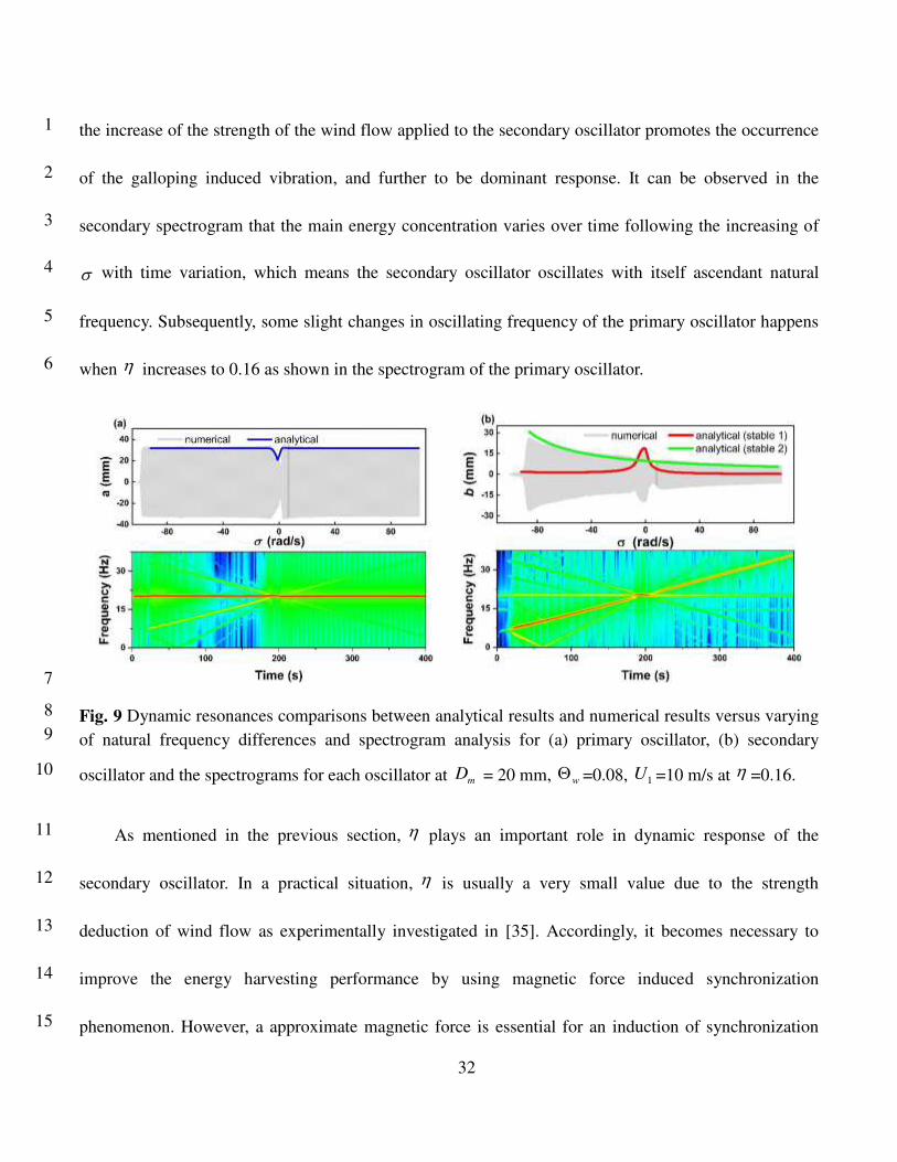
the increase of the strength of the wind flow applied to the secondary oscillator promotes the occurrence 1
of the galloping induced vibration, and further to be dominant response. It can be observed in the 2
secondary spectrogram that the main energy concentration varies over time following the increasing of 3
with time variation, which means the secondary oscillator oscillates with itself ascendant natural 4
frequency. Subsequently, some slight changes in oscillating frequency of the primary oscillator happens 5
when increases to 0.16 as shown in the spectrogram of the primary oscillator. 6
7
Fig. 9 Dynamic resonances comparisons between analytical results and numerical results versus varying 8
of natural frequency differences and spectrogram analysis for (a) primary oscillator, (b) secondary 9
oscillator and the spectrograms for each oscillator at mD = 20 mm, w
=0.08, 1U =10 m/s at =0.16. 10
As mentioned in the previous section, plays an important role in dynamic response of the 11
secondary oscillator. In a practical situation, is usually a very small value due to the strength 12
deduction of wind flow as experimentally investigated in [35]. Accordingly, it becomes necessary to 13
improve the energy harvesting performance by using magnetic force induced synchronization 14
phenomenon. However, a approximate magnetic force is essential for an induction of synchronization 15
Page 34
33
because a strongly mode coupling will result in a structural binding phenomenon, which cause the 2-1
DOF system collapse to a 1-DOF system. On the other hand, an extremely weak coupling would cause 2
invalidation of mode coupling, and thus make synchronization phenomenon hard to happen. In this study, 3
we investigated the influence of magnet distance to the responses of both oscillators. Subsequently, we 4
investigated the dynamic responses of both the oscillators with a small magnet distance for a strongly 5
mechanical coupling, and the results are illustrated in Fig. 10. It can be observed that both of the primary 6
and secondary oscillators are totally bounded to each other, and they have almost the same dynamic 7
behaviors over the varying frequency range. Based on the prediction accuracy point, it can be found that 8
the analytical prediction results showed in the Fig. 10(a) and (b) does not give an accurate amplitude 9
matching with that of the numerical results. The difference between numerical results and analytical 10
prediction happens because chaos phenomenon happens in this strongly coupled system as detuning 11
parameter varies, and chaos itself is hard to be predicted. In the spectrogram of each oscillator in 12
second row of Fig. 10, it can be identified that a frequency evolution happens over time, especially, the 13
frequencies evolution is irregular and infinite in the chaos regions. The other regime except the chaos 14
ones also shows a quasi-chaos state even though the dominant frequencies exhibit the same trend of 15
gradual increasing for both of the oscillators. 16
Page 35
34
1
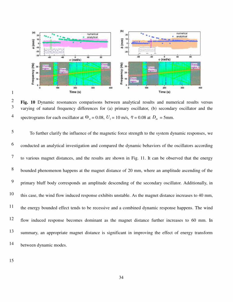
Fig. 10 Dynamic resonances comparisons between analytical results and numerical results versus 2
varying of natural frequency differences for (a) primary oscillator, (b) secondary oscillator and the 3
spectrograms for each oscillator at w = 0.08, 1U = 10 m/s, = 0.08 at m
D = 5mm. 4
To further clarify the influence of the magnetic force strength to the system dynamic responses, we 5
conducted an analytical investigation and compared the dynamic behaviors of the oscillators according 6
to various magnet distances, and the results are shown in Fig. 11. It can be observed that the energy 7
bounded phenomenon happens at the magnet distance of 20 mm, where an amplitude ascending of the 8
primary bluff body corresponds an amplitude descending of the secondary oscillator. Additionally, in 9
this case, the wind flow induced response exhibits unstable. As the magnet distance increases to 40 mm, 10
the energy bounded effect tends to be recessive and a combined dynamic response happens. The wind 11
flow induced response becomes dominant as the magnet distance further increases to 60 mm. In 12
summary, an appropriate magnet distance is significant in improving the effect of energy transform 13
between dynamic modes. 14
15
Page 36
35
-100 -50 0 50 10024
26
28
30
32
a (
mm
)
rad/s
Dm = 20mm
Dm = 40mm
Dm = 60mm
(a)
0
5
10
0
5
10
-100 -50 0 50 1000
5
10
Dm = 20mm(b)
b (
mm
)
Dm = 40mm
Dm = 60mm
rad/s
1
Fig. 11 Dynamic resonances comparisons versus varying of natural frequency differences for (a) 2
primary oscillator, (b) secondary oscillator under different magnet distances of 20 mm, 40mm and 60 3
mm. 4
4.2 Performance evaluation 5
The 1:1 internal resonance is adopted for the mode synchronization between the oscillators, and 6
thus the output performances are expected to be effectively improved. In this study, a maximum power 7
based on an optimal resistance is assumed to evaluate the output performance. 8
The total RMS voltage are calculated to combine the output voltages from the primary and 9
secondary oscillators according to Eq. (35) with an optimal resistance of 0.18 MΩ. Subsequently, the 10
total maximum average power can be calculated according to Eq. (36). As shown in Fig. 12, the output 11
voltage and average power undergoes a dramatic decrease when near zero (namely the difference 12
between two natural frequency is closed to zero) at an extremely small magnet distance of 15 mm, 13
because a collapse of degree freedom number happens when the coupling force exceeds a throttle value. 14
It can be seen that total RMS voltage with the maximum value of about 60 V and average power of 15
Page 37
36
0.021 W with two peaks happens near the position when is zero as the magnet distance increases to 1
20 mm. Subsequently, as we continually increase the magnet distance to 25 mm, two electric output 2
peaks changes to one single peak near the position where equals zero as shown in Fig. 12. 3
In summary, a significant enhancement of both the total RMS voltage and average power can be 4
achieved by exploiting of the nonlinear magnet force coupling. The 1:1 internal resonance of two 5
oscillators leads to frequency synchronization as natural frequencies of two oscillators are closed to each 6
other, and further promoting the output performance enhancement. 7
-40 -20 0 20 4030
40
50
60
Dm = 15 mm
Dm = 20 mm
Dm = 25 mmTo
tal R
MS
vo
lta
ge
(V
)
(rad/s)
(a)
-40 -20 0 20 400.0
0.1
0.2
0.3
To
tal
av
era
ge
po
we
r (m
w)
(rad/s)
Dm = 15 mm
Dm = 20 mm
Dm = 25 mm
(b)
8
Fig. 12 (a) Total RMS voltages and (b) average powers against various under different magnet 9
distance of 15 mm, 20 mm and 25 mm. 10
11
5 Conclusions 12
In this study, we proposed a technique of 1:1 internal resonance to improve the output performance 13
in a magnetically coupled wind energy harvester with two tandem oscillators which are arranged along 14
the wind flow direction. The proposed technique was numerical and analytically verified advantageous, 15
Page 38
37
while a significant improvement of total RMS voltage and average power are readily achieved as the 1
frequency synchronization happens when the two natural frequency equals to each other. 2
The magnetically coupled governing equations representing the transverse dynamics of the bluff 3
bodies and electric circuitry are derived based on the extended Hamilton principle. The oscillating wake 4
generated by the primary bluff body are considered in the proposed model to investigate the dynamic 5
behaviors of both the oscillators. The approximate analytical solutions of the resulting model are 6
determined using a perturbation technique: the method of multiple scales. After mathematical 7
manipulation, a set of modulation equations are obtained to predict the overall static dynamic responses. 8
The proportional wind flow constant is newly defined in this study to describe the wind velocity 9
reduction to the secondary bluff body. A series of parametric studies are carried out to obtain a 10
comprehensive understanding of the relationships between the system dynamic behaviors and the 11
parameters including wind velocity 1U , frequency detuning parameter and oscillating wake 12
coefficient w with absence of magnetic force. The comparisons between the analytical prediction 13
solutions and numerical results are also conducted, which exhibits a very good matching between them. 14
Several saddle-node bifurcation analyses are conducted to reveal the nature of the system with w 15
and w plane. The cusp bifurcation and synchronization region are found out based on the 16
bifurcation analyses. 17
The frequency synchronization under magnetic coupling can be triggered as the natural frequencies 18
of the oscillators close to each other under a suitable magnet distance and verified both in analytical 19
Page 39
38
prediction solutions and numerical results. The total RMS voltages and average power generated by both 1
of the oscillators shows a significant improvement when the magnet distance larger than 15 mm which is 2
benefit to promote the improvement of energy harvesting performance. This study provides an important 3
guideline for the design of a magnetically coupled high-efficiency 2-DOF wind energy harvester using 4
the 1:1 internal mode resonance. It is expected that the proposed method has a potential in designing 5
compact and efficient wind energy harvesters and broad and practical industrial applications such as 6
wireless sensor networks in the future. 7
8
Acknowledgments 9
This work was supported by the National Natural Science Foundation of China (5210051321) and 10
Scientific Research foundation for Talented Scholars of Jiangsu University (5501730000). 11
Data availability statement 12
All data generated or analysed during this study are included in this published article (and its 13
supplementary information files). 14
15
Conflict of Interest 16
The authors declare that they have no conflict of interest. 17
References 18
1. Zhang, L., Meng, B., Xia, Y., Deng, Z., Dai, H., Hagedorn, P., et al.: Galloping triboelectric 19
nanogenerator for energy harvesting under low wind speed. Nano Energy. 70, 104477 (2020) 20
https://doi.org/10.1016/j.nanoen.2020.104477 21
Page 40
39
2. Wang, G., Liao, W.-H., Zhao, Z., Tan, J., Cui, S., Wu, H., et al.: Nonlinear magnetic force and 1
dynamic characteristics of a tri-stable piezoelectric energy harvester. Nonlinear Dynamics. 97(4), 2
2371-97 (2019) https://doi.org/10.1007/s11071-019-05133-z 3
3. Maamer, B., Boughamoura, A., Fath El-Bab, A.M.R., Francis, L.A., Tounsi, F.: A review on design 4
improvements and techniques for mechanical energy harvesting using piezoelectric and 5
electromagnetic schemes. Energy Convers Manage. 199, 111973 (2019) 6
https://doi.org/10.1016/j.enconman.2019.111973 7
4. Dai, J., Tan, Y., Shen, X.: Investigation of energy output in mountain wind farm using multiple-units 8
SCADA data. Appl Energy. 239, 225-38 (2019) https://doi.org/10.1016/j.apenergy.2019.01.207 9
5. Kaplan, Y.A., Agalar, S., Bildircin, H.: General situation of wind energy source in Turkey and wind 10
turbine technologies. International Journal of Renewable Energy Technology. 10(1-2), 56-67 (2019) 11
https://doi.org/10.1504/IJRET.2019.097004 12
6. Sun, W., Jang, H., Seok, J.: Magnetically coupled piezoelectric galloping-based energy harvester 13
using a tandem configuration. Mechanical Systems and Signal Processing. 161, 107952 (2021) 14
https://doi.org/10.1016/j.ymssp.2021.107952 15
7. Hu, G., Wang, J., Tang, L.: A comb-like beam based piezoelectric system for galloping energy 16
harvesting. Mechanical Systems and Signal Processing. 150, 107301 (2021) 17
https://doi.org/10.1016/j.ymssp.2020.107301 18
8. Tan, T., Hu, X., Yan, Z., Zou, Y., Zhang, W.: Piezoelectromagnetic synergy design and performance 19
analysis for wind galloping energy harvester. Sensors and Actuators A: Physical. 302, 111813 (2020) 20
https://doi.org/10.1016/j.sna.2019.111813 21
9. Hu, G., Liang, J., Lan, C., Tang, L.: A twist piezoelectric beam for multi-directional energy harvesting. 22
Smart Mater Struct. 29(11), 11lt01 (2020) https://doi.org/10.1088/1361-665X/abb648 23
10. Pan, J., Qin, W., Deng, W., Zhang, P., Zhou, Z.: Harvesting weak vibration energy by integrating 24
piezoelectric inverted beam and pendulum. Energy. 227, 120374 (2021) 25
https://doi.org/10.1016/j.energy.2021.120374 26
11. Zhao, L., Tang, L., Yang, Y.: Comparison of modeling methods and parametric study for a 27
piezoelectric wind energy harvester. Smart Mater Struct. 22(12), 125003 (2013) 28
https://doi.org/10.1088/0964-1726/22/12/125003 29
12. Rezaei-Hosseinabadi, N., Tabesh, A., Dehghani, R.: A Topology and Design Optimization Method 30
for Wideband Piezoelectric Wind Energy Harvesters. IEEE Transactions on Industrial Electronics. 31
63(4), 2165-73 (2015) https://doi.org/10.1109/tie.2015.2499248 32
13. Hu, G., Wang, J., Su, Z., Li, G., Peng, H., Kwok, K.C.S.: Performance evaluation of twin 33
piezoelectric wind energy harvesters under mutual interference. Appl Phys Lett. 115(7), 073901 (2019) 34
https://doi.org/10.1063/1.5109457 35
14. Sun, W., Seok, J.: Novel galloping-based piezoelectric energy harvester adaptable to external wind 36
velocity. Mechanical Systems and Signal Processing. 152, 107477 (2021) 37
https://doi.org/10.1016/j.ymssp.2020.107477 38
15. Sun, W., Seok, J.: A novel self-tuning wind energy harvester with a slidable bluff body using vortex-39
Page 41
40
induced vibration. Energy Convers Manage. 205, 112472 (2020) 1
https://doi.org/10.1016/j.enconman.2020.112472 2
16. Zhao, D., Hu, X., Tan, T., Yan, Z., Zhang, W.: Piezoelectric galloping energy harvesting enhanced by 3
topological equivalent aerodynamic design. Energy Convers Manage. 222, 113260 (2020) 4
https://doi.org/10.1016/j.enconman.2020.113260 5
17. Zhao, K., Zhang, Q., Wang, W.: Optimization of Galloping Piezoelectric Energy Harvester with V-6
Shaped Groove in Low Wind Speed. Energies. 12(24), 4619-36 (2019) 7
https://doi.org/10.3390/en12244619 8
18. Lee, Y.J., Zhou, G., Lua, K.B.: Two-dimensional numerical study of isotoxal-star polygonal 9
cylinders in cross-flow. Journal of Wind Engineering and Industrial Aerodynamics. 188, 125-35 (2019) 10
https://doi.org/10.1016/j.jweia.2019.02.020 11
19. Wang, J., Tang, L., Zhao, L., Zhang, Z.: Efficiency investigation on energy harvesting from airflows 12
in HVAC system based on galloping of isosceles triangle sectioned bluff bodies. Energy. 172, 1066-78 13
(2019) https://doi.org/10.1016/j.energy.2019.02.002 14
20. Zhou, C., Zou, H.-X., Wei, K.-X., Liu, J.: Enhanced performance of piezoelectric wind energy 15
harvester by a curved plate. Smart Mater Struct. 28(12), 125022 (2019) https://doi.org/10.1088/1361-16
665X/ab525a 17
21. Tucker Harvey, S., Khovanov, I.A., Murai, Y., Denissenko, P.: Characterisation of aeroelastic 18
harvester efficiency by measuring transient growth of oscillations. Appl Energy. 268, 115014 (2020) 19
https://doi.org/10.1016/j.apenergy.2020.115014 20
22. Yang, K., Qiu, T., Wang, J., Tang, L.: Magnet-induced monostable nonlinearity for improving the 21
VIV-galloping-coupled wind energy harvesting using combined cross-sectioned bluff body. Smart 22
Mater Struct. 29(7), 07LT1 (2020) https://doi.org/10.1088/1361-665X/ab874c 23
23. Wang, J., Gu, S., Zhang, C., Hu, G., Chen, G., Yang, K., et al.: Hybrid wind energy scavenging by 24
coupling vortex-induced vibrations and galloping. Energy Convers Manage. 213, 112835 (2020) 25
https://doi.org/10.1016/j.enconman.2020.112835 26
24. Yang, X., He, X., Li, J., Jiang, S.: Modeling and verification of piezoelectric wind energy harvesters 27
enhanced by interaction between vortex-induced vibration and galloping. Smart Mater Struct. 28(11), 28
115027 (2019) https://doi.org/10.1088/1361-665X/ab4216 29
25. Sun, W., Jo, S., Seok, J.: Development of the optimal bluff body for wind energy harvesting using 30
the synergetic effect of coupled vortex induced vibration and galloping phenomena. International 31
Journal of Mechanical Sciences. 156, 435-45 (2019) https://doi.org/10.1016/j.ijmecsci.2019.04.019 32
26. Lan, C., Tang, L., Hu, G., Qin, W.: Dynamics and performance of a two degree-of-freedom 33
galloping-based piezoelectric energy harvester. Smart Mater Struct. 28(4), 045018 (2019) 34
https://doi.org/10.1088/1361-665X/ab0852 35
27. Zhao, L., Tang, L., Yang, Y.: Enhanced piezoelectric galloping energy harvesting using 2 degree-of-36
freedom cut-out cantilever with magnetic interaction. Jpn J Appl Phys. 53(6), 060302 (2014) 37
https://doi.org/10.7567/JJAP.53.060302 38
28. Wang, J., Geng, L., Yang, K., Zhao, L., Wang, F., Yurchenko, D.: Dynamics of the double-beam 39
Page 42
41
piezo–magneto–elastic nonlinear wind energy harvester exhibiting galloping-based vibration. 1
Nonlinear Dynamics. 100(3), 1963-83 (2020) https://doi.org/10.1007/s11071-020-05633-3 2
29. Yang, W., Towfighian, S.: Internal resonance and low frequency vibration energy harvesting. Smart 3
Mater Struct. 26(9), 095008 (2017) https://doi.org/10.1088/1361-665X/aa791d 4
30. Clementi, F., Lenci, S., Rega, G.: 1:1 internal resonance in a two d.o.f. complete system: a 5
comprehensive analysis and its possible exploitation for design. Meccanica. 55(6), 1309-32 (2020) 6
https://doi.org/10.1007/s11012-020-01171-9 7
31. Jiang, W.-A., Ma, X.-D., Han, X.-J., Chen, L.-Q., Bi, Q.-S.: Broadband energy harvesting based on 8
one-to-one internal resonance. Chinese Physics B. 29(10), 100503 (2020) 9
https://doi.org/10.1088/1674-1056/aba5fd 10
32. Jiang, W., Han, X., Chen, L., Bi, Q.: Improving energy harvesting by internal resonance in a spring-11
pendulum system. Acta Mechanica Sinica. 36(3), 618-23 (2020) https://doi.org/10.1007/s10409-020-12
00945-4 13
33. Pu, D., Wei, X., Xu, L., Jiang, Z., Huan, R.: Synchronization of electrically coupled 14
micromechanical oscillators with a frequency ratio of 3:1. Appl Phys Lett. 112(1), 013503 (2018) 15
https://doi.org/10.1063/1.5000786 16
34. Cao, D.X., Leadenham, S., Erturk, A.: Internal resonance for nonlinear vibration energy harvesting. 17
The European Physical Journal Special Topics. 224(14-15), 2867-80 (2015) 18
https://doi.org/10.1140/epjst/e2015-02594-4 19
35. Sun, W., Guo, F., Seok, J.: Development of a novel vibro-wind galloping energy harvester with high 20
power density incorporated with a nested bluff-body structure. Energy Convers Manage. 197, 111880 21
(2019) https://doi.org/10.1016/j.enconman.2019.111880 22
36. Lan, C., Tang, L., Qin, W., Xiong, L.: Magnetically coupled dual-beam energy harvester: Benefit and 23
trade-off. J Intell Mater Syst Struct. 29(6), 1216-35 (2017) 24
https://doi.org/10.1177/1045389x17730927 25
37. Meseguer, J., Sanz-André s, A., Alonso, G.: Determination of Maximum Mechanical Energy 26
Efficiency in Energy Galloping Systems. J Eng Mech. 141(1), 04014101 (2015) 27
https://doi.org/10.1061/(asce)em.1943-7889.0000817 28
38. Abdelkefi, A., Yan, Z., Hajj, M.R.: Performance analysis of galloping-based piezoaeroelastic energy 29
harvesters with different cross-section geometries. J Intell Mater Syst Struct. 25(2), 246-56 (2014) 30
https://doi.org/10.1177/1045389X13491019 31
39. Tang, L., Zhao, L., Yang, Y., Lefeuvre, E.: Equivalent Circuit Representation and Analysis of 32
Galloping-Based Wind Energy Harvesting. IEEE/ASME Transactions on Mechatronics. 20(2), 834-44 33
(2015) https://doi.org/10.1109/tmech.2014.2308182 34
40. Bibo, A., Daqaq, M.F.: An analytical framework for the design and comparative analysis of 35
galloping energy harvesters under quasi-steady aerodynamics. Smart Mater Struct. 24(9), 094006 36
(2015) https://doi.org/10.1088/0964-1726/24/9/094006 37


![Galloping Gourmet Perfection Aire Manual[1]](https://static.documents.pub/doc/80x56/54fd70ee4a7959fc798b46a0/galloping-gourmet-perfection-aire-manual1.jpg)


