Page 1
International Journal of Engineering & Technology IJET-IJENS Vol:14 No:01 58
142101-7474-IJET-IJENS © February 2014 IJENS I J E N S
Abstract— There is considerable interest in the use of Single
Carrier Frequency Division Multiple Access (SC-FDMA) as the
uplink transmission scheme in the Third-generation Partnership
Project-Long Term Evolution 3GPP-LTE standard. This interest
is justified by the inherent single carrier structure of SC-FDMA,
which results in reduced sensitivity to phase noise and a lower
Peak-to-Average Power Ratio (PAPR) compared to Orthogonal
Frequency Division Multiple Access OFDMA. This consequently
makes it more attractive for low cost devices with limited transmit
power. In this paper the LTE and SCFDMA specifications will be
explained in details and the performance of the system will be
examined under two types of equalization method which are zero
forcing ZF and minimum mean square error MMSE method.
Also the system was tested under two types of subcarrier mapping
which are localized and distributed mapping in two types of
channel models which are International Telecommunications
Union (ITU) and Stanford University Interim (SUI). The results
show that the system gives better performance with localized
distributed mode and also give good performance with the
minimum mean square error MMSE method and the system will
give different response through the different channel cases.
Index Term— LTE, SCFDMA, PAPR, ZF, MMSE, ITU
channel, SUI channel
I. INTRODUCTION
Just a decade ago mobile communications was mainly focusing
on speech transmission, while nowadays mobile internet and
multimedia applications demand for high data rates and a high
quality of service of communications links [1].
Wireless communications is moving rapidly towards small,
low cost devices. However, the mobility and value of these
devices is often limited by battery life since device
miniaturization is progressing at a faster rate than battery
technology optimization. Thus, the issue of battery life
represents a key concern in the next generation of wireless
communication systems [2].
Raad Farhood Chisab, Author is with the Ministry of Higher Education and
Scientific Research in Iraq-Foundation of Technical Education-institute of technology in Baghdad. Also he is pursuing Ph.D. Scholarship at Electronic
and Communication Engineering Department-Sam Higginbottom Institute of
Agriculture, Technology and Science (SHIATS) (Deemed to be university), Allahabad 211007, UP, India. (Corresponding author to provide Email:
[email protected] ).
Prof. (Dr.) C. K. Shukla, Author is Professor at Electronic and Communication Engineering Department-Sam Higginbottom Institute of
Agriculture, Technology and Science (SHIATS) (Deemed to be university),
Allahabad 211007, UP, India. E-mail: [email protected]
To go beyond 3G, 4G (4th Generation) mobile networks are
evolving to provide a comprehensive IP-based integrated
solution at an affordable price where voice, data and streamed
multimedia can be given to users on an anytime, anywhere
basis, and at higher data rates than previous generations. This
will be achieved after the convergence of all types of wired and
wireless technologies and will be capable of providing data
rates between 100 Mbps and 1 Gbps (both indoors and
outdoors), with premium quality and high security. High data
rate calls upon an improved spectral efficiency [3].
The Third Generation Partnership Project Long Term
Evolution 3GPP-LTE radio access standard is based on shared
channel access providing peak data rates of 50 Mbps in the
uplink and 100 Mbps in the downlink [4]. SCFDMA has been
proposed for use on the uplink of the LTE standard [5]
II. LTE FUNDAMENTAL OVERVIEW
Long Term Evolution started in December 2004. The
objective was to develop a framework for the evolution of the
3GPP radio access technology towards a high-data-rate,
low-latency, and packet-optimized radio access technology [6].
3GPP standard is focused on next generation cellular systems
called Long Term Evolution (LTE) [7],[8]. The scalable
bandwidth of LTE is 1.25MHz-20MHz. The LTE features are
high peak data rate, flexibility of spectrum usage, low latency
times, and higher capacity per cell. LTE is based on OFDMA in
the downlink and SC-FDMA in the uplink [9].
The linear convolution of the multipath channel is
transformed into circular convolution, which enables the
receiver to equalize each subcarrier present in the channel by
scaling with a complex gain factor. The main advantage of
SCFDMA over OFDMA is low PAPR. As it has got lower
PAPR, the power efficiency is high [10].
Talking more explicitly, main objectives and targets of LTE
development can be stated as follows [11]:
1. Increase in system capacity and reduced cost per bit,
as well as utilization of existing 2G and 3G spectrum
along with the new spectrum.
2. Achieving of notably higher data rates weighed
against the existing 3G systems, with goal of 100Mbps
in uplink and over 50Mbps in downlink.
3. Greater coverage by providing higher data rates over
wider areas and flexibility of use of existing and new
frequency bands
4. Attaining higher system capacity up to three times the
Performance Evaluation of 4G-LTE-SCFDMA
Scheme under SUI and ITU Channel Models
Raad Farhood Chisab, Member IEEE and Prof. (Dr.) C. K. Shukla
Page 2
International Journal of Engineering & Technology IJET-IJENS Vol:14 No:01 59
142101-7474-IJET-IJENS © February 2014 IJENS I J E N S
capacity of current systems and increased service
provisioning more services at lower cost with better
user experience.
Some key requirements and capability targets for the LTE
are [12],[13]:
1. Low latency : for both user plane and control plane,
with a 5MHz spectrum allocation the latency target is
below 5 ms
2. Bandwidth Scalability : different bandwidths can be
used depending upon the requirements (1.25 to 20
MHz)
3. Peak Data Rates : 100 Mbps for DL , 50 Mbps for UL
4. 2 to 4 times capacity over existing Release 6 scenarios
with HSDPA
5. Only Packet Switched Domain support
6. Improved Cell edge performance
7. Inter-working with the existing 2G and 3G systems
and non-3GPP systems
8. Optimized for low mobile speed but also support high
mobile speeds
9. Reduction of complexity in both system and terminals
Ease of migration from existing networks
The LTE SC-FDMA subcarrier spacing equals 15 kHz. The
selection of the subcarrier spacing in an SCFDMA based
system needs to carefully balance overhead from the cyclic
prefix against sensitivity to Doppler shift and other types of
frequency errors and inaccuracies. The choice of 15 kHz for the
LTE subcarrier spacing was found to offer a good balance
between these two constraints. Assuming an FFT-based
transmitter/receiver implementation, 15 kHz subcarrier spacing
corresponds to a sampling rate where NFFT is
the FFT size. It is important to understand though that the LTE
specifications do not in any way mandate the use of FFT-based
transmitter/ receiver implementations and even less so a
particular FFT size or sampling rate. Nevertheless, FFT-based
implementations of OFDM are common practice and an FFT
size of 2048, with a corresponding sampling rate of 30.72 MHz,
is suitable for the wider LTE carrier bandwidths, such as
bandwidths of the order of 15 MHz and above. However, for
smaller carrier bandwidths, a smaller FFT size and a
correspondingly lower sampling rate can very well be used
[14].
In frequency domain 12 subcarriers are grouped together and
make up the Resource Block RB in one slot as shown in Fig. 1.
So a Resource Block occupies 180 KHz in the frequency
domain and 0.5 ms in the time domain [11].
A resource element, consisting of one subcarrier during one
OFDM symbol, is the smallest physical resource in LTE.
Furthermore, as illustrated in Fig. 1, resource elements are
grouped into resource blocks. Each resource block thus consists
of 7*12=84 resource elements in the case of a normal cyclic
prefix and 6*12=72 resource elements in the case of an
extended cyclic prefix. Although resource blocks are defined
over one slot, the basic time-domain unit for dynamic
scheduling in LTE is one sub-frame, consisting of two
consecutive slots. The minimum scheduling unit consisting of
two time-consecutive resource blocks within one sub frames
(one resource block per slot), can be referred to as a
resource-block pair [14].
Fig. 1. The Resource Block in LTE
Transmission parameters in LTE consist of frequency, space,
and time to create transmission resources for carrying data. All
of the time units in LTE are specified as a factor of ⁄ in which 2048 is the FFT length. The LTE
radio frame for downlink and uplink transmission is long. LTE supports two radio frame structures
[15]:
1. FDD (Frequency division duplex), which uses type 1
frame structure.
2. TDD (Time division duplex), which is applicable to
type2 frame structure.
A radio frame consists of 10 sub frames in FDD and two half- frames in TDD as shown in Fig. 2. A half-frame is
divided into four sub frames and a special sub frame, or five sub
frames, based on downlink to uplink switch point periodicity.
The TDD frame structure can be configured in seven different
sub frame formats; however sub frames 0 and 5 and DwTS are
reserved for downlink transmission. The sub frame that appears
after special sub frame as well as UpPTS, is always assigned to
uplink transmission. Each sub frame in both FDD and TDD has
two slots of . The important
parameters of LTE can be found in Table I
TABLE I
THE DOMINANT PARAMETERS OF 3GPP-LTE
Parameters Quantity
BW (MHz) 1.25 2.5 5 10 15 20 Resource Block 6 12 25 50 75 100
FFT Size 128 256 512 1024 1536 2048
Fs.(MHz) 1.92 3.84 7.68 15.36 23.04 30.72 Sample per slot 960 1920 3840 7680 11520 15360
No. sub carrier 76 151 301 601 901 1201
Carrier spacing 15 KHz (PRB) BW 180 KHz
Full mobility Up to 500 Km/h
Capacity > 200 User per cell Cell size 5-100 Km
III. SCFDMA
Nowadays, mobile radio system is immersed by more and
Page 3
International Journal of Engineering & Technology IJET-IJENS Vol:14 No:01 60
142101-7474-IJET-IJENS © February 2014 IJENS I J E N S
more services with data rate from few Kbit/s up to several
Mbit/s. Presently, research beyond 3rd generation mobile radio
systems is in progress worldwide to enable the future mobile
radio system supporting different types of services with
different data rates and providing high flexibility and high
performance. An important decision for the future mobile radio
system is the choice of the multiple access schemes [16].
SC-FDMA has drawn great attention as an attractive
alternative to OFDMA, especially in the uplink
communications where lower PAPR greatly benefits the mobile
terminal in terms of transmit power efficiency. SC-FDMA has
been adopted for the uplink multiple access scheme for the 3rd
Generation Partnership Project (3GPP) Long Term Evolution
(LTE) [17].
SC-FDMA is a single carrier block transmission technique
with cyclic prefix (CP). Each block is called an SC-FDMA
symbol [18]. With the aid of CP, SC-FDMA converts the
multipath frequency selective fading channel into several flat
fading sub-channels and enables efficient frequency domain
equalization (FDE) at the receiver. SC-FDMA signals have low
PAPR, which greatly increases the power efficiency of user
equipment (UEs) [19].
When the channel is in good condition, the transmission is
performed with higher data rates (such as 64QAM), and when
the channel is in poor condition, the transmission rate is
lowered (such as QPSK) with small constellation and low-rate
codes. The channel side information is feedback to transmitter
in order to control transmit power; transmit constellation and
the coding rate. The resource allocation and modulation would
give a distribution as in Fig. 2. In this figure it can show that
how each user get its modulation type and get its time allocation
and fixed amount of subcarrier according to channel type that
the signal will transfer through it. The power level of the
modulation is adjusted to overcome the fading of the channel.
The channel may be assumed to be reciprocal. BS is able to
estimate the channel of all BS-to-mobile links based on the
received uplink transmission as long as the channel variation is
slow [20].
Fig. 2. The resource allocation and modulation for each user in SC-FDMA
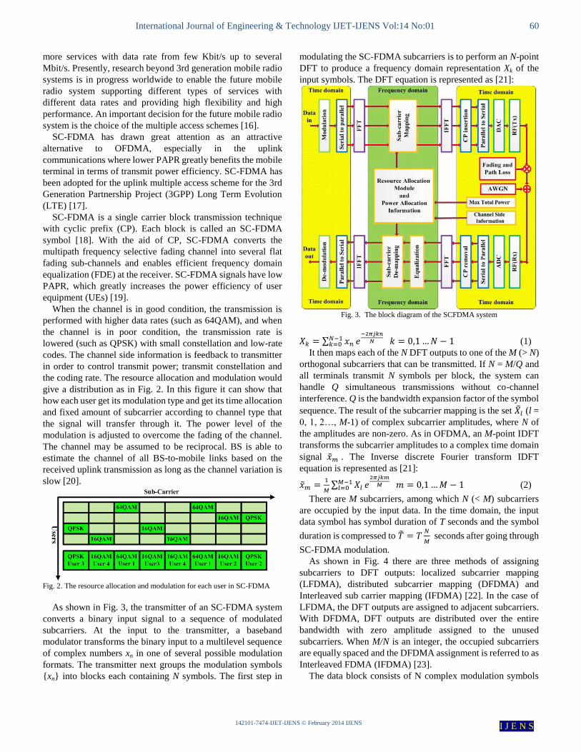
As shown in Fig. 3, the transmitter of an SC-FDMA system
converts a binary input signal to a sequence of modulated
subcarriers. At the input to the transmitter, a baseband
modulator transforms the binary input to a multilevel sequence
of complex numbers xn in one of several possible modulation
formats. The transmitter next groups the modulation symbols
{xn} into blocks each containing N symbols. The first step in
modulating the SC-FDMA subcarriers is to perform an N-point
DFT to produce a frequency domain representation Xk of the
input symbols. The DFT equation is represented as [21]:
Fig. 3. The block diagram of the SCFDMA system
∑
(1)
It then maps each of the N DFT outputs to one of the M (> N)
orthogonal subcarriers that can be transmitted. If N = M/Q and
all terminals transmit N symbols per block, the system can
handle Q simultaneous transmissions without co-channel
interference. Q is the bandwidth expansion factor of the symbol
sequence. The result of the subcarrier mapping is the set (l =
0, 1, 2…, M-1) of complex subcarrier amplitudes, where N of
the amplitudes are non-zero. As in OFDMA, an M-point IDFT
transforms the subcarrier amplitudes to a complex time domain
signal . The Inverse discrete Fourier transform IDFT
equation is represented as [21]:
∑
(2)
There are M subcarriers, among which N (< M) subcarriers
are occupied by the input data. In the time domain, the input
data symbol has symbol duration of T seconds and the symbol
duration is compressed to
seconds after going through
SC-FDMA modulation.
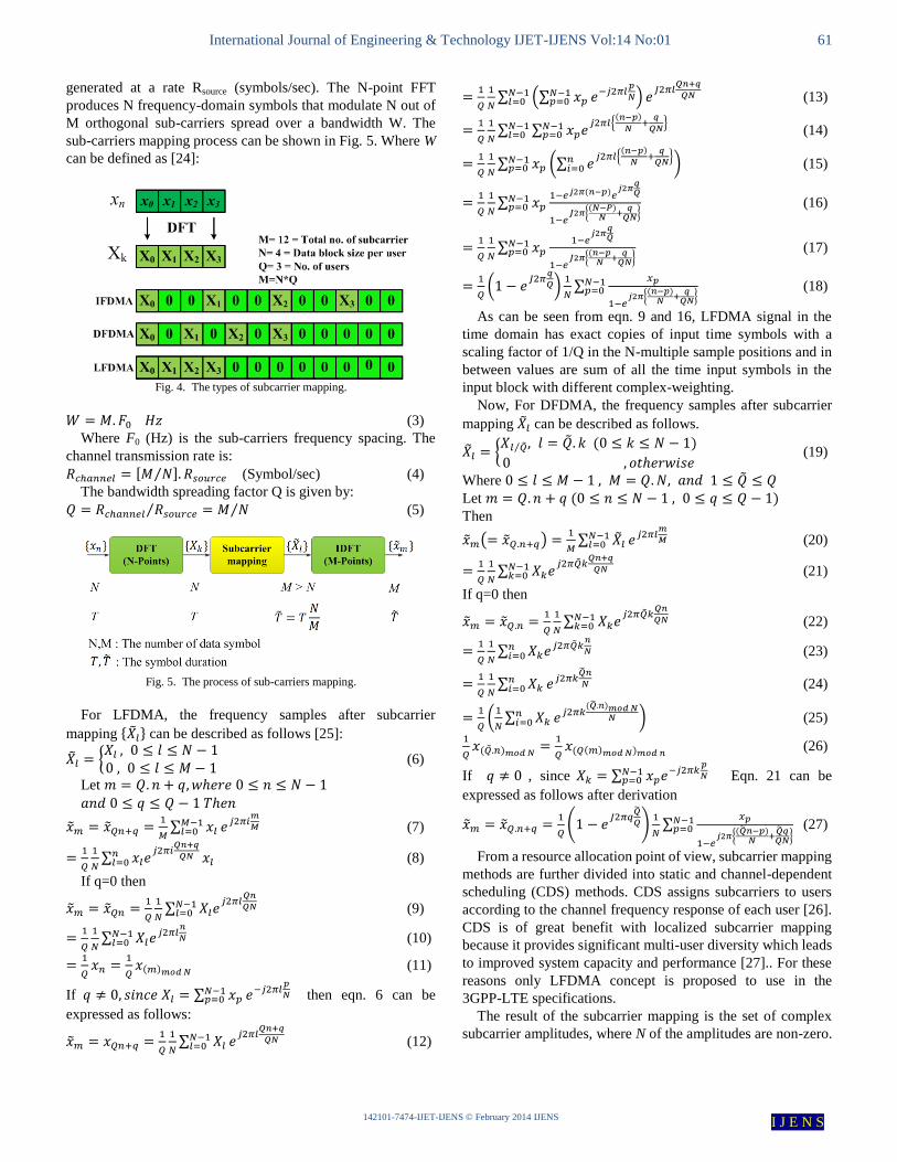
As shown in Fig. 4 there are three methods of assigning
subcarriers to DFT outputs: localized subcarrier mapping
(LFDMA), distributed subcarrier mapping (DFDMA) and
Interleaved sub carrier mapping (IFDMA) [22]. In the case of
LFDMA, the DFT outputs are assigned to adjacent subcarriers.
With DFDMA, DFT outputs are distributed over the entire
bandwidth with zero amplitude assigned to the unused
subcarriers. When M/N is an integer, the occupied subcarriers
are equally spaced and the DFDMA assignment is referred to as
Interleaved FDMA (IFDMA) [23].
The data block consists of N complex modulation symbols
Page 4
International Journal of Engineering & Technology IJET-IJENS Vol:14 No:01 61
142101-7474-IJET-IJENS © February 2014 IJENS I J E N S
generated at a rate Rsource (symbols/sec). The N-point FFT
produces N frequency-domain symbols that modulate N out of
M orthogonal sub-carriers spread over a bandwidth W. The
sub-carriers mapping process can be shown in Fig. 5. Where W
can be defined as [24]:
Fig. 4. The types of subcarrier mapping.
(3)
Where F0 (Hz) is the sub-carriers frequency spacing. The
channel transmission rate is:
[ ⁄ ] (Symbol/sec) (4)
The bandwidth spreading factor Q is given by:
⁄ ⁄ (5)
Fig. 5. The process of sub-carriers mapping.
For LFDMA, the frequency samples after subcarrier
mapping { } can be described as follows [25]:
{
(6)
Let
∑
(7)
∑
(8)
If q=0 then
∑
(9)
∑
(10)
(11)
If ∑
then eqn. 6 can be
expressed as follows:
∑
(12)
∑ (∑
)
(13)
∑ ∑
{
}
(14)
∑ (∑
{
}
) (15)
∑
{
} (16)
∑
{
} (17)
(
)
∑
{
}
(18)
As can be seen from eqn. 9 and 16, LFDMA signal in the
time domain has exact copies of input time symbols with a
scaling factor of 1/Q in the N-multiple sample positions and in
between values are sum of all the time input symbols in the
input block with different complex-weighting.
Now, For DFDMA, the frequency samples after subcarrier
mapping can be described as follows.
{ ⁄
(19)
Where
Let
Then
( )
∑
(20)
∑
(21)
If q=0 then
∑
(22)
∑
(23)
∑
(24)
(
∑
) (25)
(26)
If , since ∑
Eqn. 21 can be
expressed as follows after derivation
(
)
∑
{
}
(27)
From a resource allocation point of view, subcarrier mapping
methods are further divided into static and channel-dependent
scheduling (CDS) methods. CDS assigns subcarriers to users
according to the channel frequency response of each user [26].
CDS is of great benefit with localized subcarrier mapping
because it provides significant multi-user diversity which leads
to improved system capacity and performance [27].. For these
reasons only LFDMA concept is proposed to use in the
3GPP-LTE specifications.
The result of the subcarrier mapping is the set of complex
subcarrier amplitudes, where N of the amplitudes are non-zero.
Page 5
International Journal of Engineering & Technology IJET-IJENS Vol:14 No:01 62
142101-7474-IJET-IJENS © February 2014 IJENS I J E N S
An M-point inverse DFT (IDFT) transforms the subcarrier
amplitudes to a complex time domain signal. Each then
modulates a single frequency carrier and all the modulated
symbols are transmitted sequentially. The transmitter performs
two other signal processing operations prior to transmission. It
inserts a set of symbols referred to as a cyclic prefix (CP) in
order to provide a guard time to prevent inter-block interference
(IBI) due to multipath propagation. The transmitter also
performs a linear filtering operation referred to as pulse shaping
in order to reduce out-of-band signal energy. The receiver
transforms the received signal into the frequency domain via
DFT, performs frequency domain equalization and then
de-maps the subcarriers. Because SC-FDMA uses single carrier
modulation, it suffers from inter-symbol interference (ISI) and
thus equalization is necessary to combat the ISI. The equalized
symbols are transformed back to the time domain via IDFT, and
detection and decoding take place in the time domain.
Disadvantages of OFDMA compared to SC-FDMA are its
strong sensitivity to carrier frequency offset and strong
sensitivity to nonlinear distortion in the power amplifier due to
the high PAPR, both properties of the multicarrier nature of
OFDMA. PAPR was a major factor in selecting SC-FDMA
over OFDMA as the uplink air interface for 3GPP LTE [28].
The transmitted SCFDMA signals suffer from multipath
fading and Doppler Effect while propagating through the
wireless channel, which performs like a filter. In order to get
correct demodulation and decoding at the receiver, the channel
transfer function must be estimated by the receiver. Channel
estimation is followed by channel equalization, which simply
divides all the received data symbols by the estimated channel
transfer function. Channel estimation can be done both in time
domain and frequency domain. For an SCFDMA system FFT
need to be performed for all carriers so frequency domain
processing is straightforward [29].
The equalization can be done in two domains which are:
Equalization in time domain
Equalization in frequency domain
We can position the equalizer on time domain data symbols
and try to make these received symbols as close as possible to
the transmitted symbols. This is called Time Domain
Equalization (TEQ) which computationally complex method.
The second method to design equalizer is the Frequency
Domain Equalizer (FEQ). The frequency domain equalizer is
simple and computationally less complex as compared to time
domain equalizer. In the case of frequency domain equalization
the received signal is first transformed into frequency domain
by means of N‐point DFT and then equalization is performed as
frequency domain filtering.
In our work we have performed frequency domain linear
equalization for the received data symbols as shown in Fig. 6.
The received signal is equalized in the frequency domain.
After the equalization block the equalized signal is then
transformed back to the time domain using the IFFT by the
following steps [30]:
Let E(n) where (n=0, 1, 2…NFFT -1) denote the equalizer
coefficient for the nth
sub carrier, the time domain equalized
signal K(n) can be expressed as:
∑
(28)
Where , The equalizer coefficients
E(n) are determined to minimize the mean square error between
the equalized signal and the original signal. The equalizer
coefficients are computed according to the types of the
frequency domain equalization (FDE) in two methods as
follows [31]:
A. The zero forcing (ZF) Equalizer is
⁄ (29)
B. The Minimum Mean Square Error (MMSE) is
[| | ]⁄ (30)
Fig. 6. The process of channel equalization
Where * denotes the complex conjugate, H(n) is the transfer
function of the channel and is average energy-per-bit to
noise power spectral density. Equalization will be used to
eliminate the effect of ISI. The MMSE method is better than the
ZF method and gives lower BER compared with other method.
This improvement can be shown in Fig. 14. Therefore, in all
tests and simulations for channel models, the MMSE method
will be use.
In the receiver side, OFDMA utilizes a simple equalizer per
subcarrier after FFT. But, SC-FDMA utilizes a complex
equalizer before sending the resultant to IFFT. IFFT removes
the effect of the FFT in the transmitter. Notice that result of the
IFFT is again a time domain signal; the time domain signal is
sent to a single detector to create the bits. These differences in
receiver side are illustrated in Fig. 7. In which we can see the
equalizer simplicity of OFDMA against SC-FDMA. As you
can see, SC-FDMA receiver is more complex than OFDMA,
but in the transmitter simpler power amplifiers can be utilized
to reduce the power consumption. These fortify the SC-FDMA
as an uplink transmission scheme, since power efficiency and
complexity is important for mobile stations but not in the base
station [32].
Fig. 7. The equalization in OFDMA and SCFDMA
Page 6
International Journal of Engineering & Technology IJET-IJENS Vol:14 No:01 63
142101-7474-IJET-IJENS © February 2014 IJENS I J E N S
IV. THE CHARACTERISTICS OF THE WIRELESS
COMMUNICATION CHANNELS
In a wireless mobile communication system, a transmitted
signal propagating through the wireless channel often
encounters multiple reflective paths until it reaches the receiver
[33]. We refer to this phenomenon as multipath propagation
and it causes fluctuation of the amplitude and phase of the
received signal [34]. We call this fluctuation multipath fading
and it can occur either in large scale or in small scale as shown
in Fig. 8.
Fig. 8. The characterization of fading channel
Large-scale fading represents the average signal power
attenuation or path loss due to motion over large areas.
Small-scale fading occurs due to small changes in position and
we also call it as Rayleigh fading since the fading is often
statistically characterized with Rayleigh probability density
function (pdf). Rayleigh fading in the propagation channel,
which generates inter-symbol interference (ISI) in the time
domain, is a major impairment in wireless communications and
it significantly degrades the link performance. With a wider
transmission bandwidth, frequency selectivity of the channel
becomes more severe and thus the problem of ISI becomes
more serious. In a conventional single carrier communication
system, time domain equalization in the form of tap delay line
filtering is performed to eliminate ISI. However, in case of a
wide band channel, the length of the time domain filter to
perform equalization becomes prohibitively large since it
linearly increases with the channel response length.
The wireless communication system suffer from more than
one types of impairments that effect on the activity of the
system and this impairment can be category into three groups
which are [12]:
A. Transmission impairment due to Physical of radio
propagation which include:
1) Attenuation
The energy radiated from an omnidirectional antenna fills a
sphere, and therefore the fraction of the original energy incident
on a receiving antenna varies inversely with the distance
between the transmitting and receiving antennas. In free space
the received energy would be inversely proportional to the
square of the distance (d meters).
2) Shadowing
If attenuation were the only effect of distance on signal
strength, a signal would be received with equal power at all
points equally distant from a transmitter. However, due to
differences in the path taken by the transmitted signal, there is
noticeable variation in the power in received signals at different
points on a circle surrounding a transmitter. The effect of
shadow can be shown in Fig. 9.
Fig. 9. The effect of path loss, shadowing and Multipath on signal power
3) Doppler
When the transmitted signal is a sine wave and the
transmitter and/or receiver is moving, the frequency of a single
ray within the received signal is different from the frequency of
the transmitted signal. The difference is the Doppler shift and it
is proportional to fd = v/λ Hz, where v (in m/s) is the relative
velocity of the transmitter and receiver and λ (in meter) is the
wavelength of the transmitted sine wave [33]. For example, the
Doppler frequency of a 2 GHz sine wave at a cellular phone in a
vehicle moving at 120 km/h is fd = 222.2 Hz. The typical other
value of Doppler frequency can be shown in table II. The effect
of Doppler frequency on the channel can be shown in Fig. 10
and 11. In this figure it can notice that when the speed is high
then the effect will be increase and disturb the channel.
TABLE II
PERCEIVED MAXIMUM DOPPLER FREQUENCIES AT DIFFERENT SPEEDS AND
CARRIER FREQUENCIES
Fc V=3 Km/h V=60 Km/h V=120 Km/h
1.5 GHz 4.16 Hz 83.33 Hz 166.67 Hz
2.0 GHz 5.6 Hz 111.11 Hz 222.22 Hz
2.4 GHz 6.67 Hz 133.33 Hz 266.67 Hz
Fig. 10. The Rayleigh fading channel behavior under mobile speed of 3km/h.
Page 7
International Journal of Engineering & Technology IJET-IJENS Vol:14 No:01 64
142101-7474-IJET-IJENS © February 2014 IJENS I J E N S
Fig. 11. The Rayleigh fading channel behavior under mobile speed of 60km/h.
4) Inter-Symbol Interference
Multipath propagation is a pervasive phenomenon in cellular
signal transmission. Due to the features of the operating
environment, components of the transmitted signal arrive at the
receiver after reflections from the ground and various natural
features and manmade structures as shown in Fig. 12.
Therefore, the impulse response of the channel can be modeled
as a set of impulses arriving with relative delays proportional to
the path lengths of the different signal components.
Fig. 12. The radio propagation effects.
5) Flat Fading and Frequency-Selective Fading
When the signal bandwidth BS Hz is small compared to
the width of the frequency response, the fast fading is referred
to as “flat” because all the frequency components of the
transmitted signal are attenuated approximately equally.
Otherwise the fast fading is “frequency selective”. By other
word in the flat fading channel the BWchannel> BWsignal while in
case of selective fading channel the BWchannel< BWsignal .the
effect of flat fading and selective fading channel on the signal
transfer through these channels can be shown in Fig.13.
B. Transmission impairment due to extraneous signals
which include:
1) Co-Channel Interference
Co-channel interference is a well-known consequence of
cellular reuse. In order to use the cellular radio spectrum
efficiently, several base stations in a service area use the same
physical channels simultaneously.
2) Adjacent Channel Interference
Adjacent channel interference also occurs in all cellular
systems. Even though a signal occupies a nominal bandwidth
3) Noise
Co-channel interference and adjacent channel interference
are effects of signals generated by a cellular system and
therefore under the control of the cellular network operator.
C. Transmission impairment due to transmitting and
receiving equipment which include:
1) Thermal Noise
Thermal noise in device electronics enhances the
atmospheric noise power in a radio receiver. The added noise is
usually expressed as a receiver noise figure, which is the ratio
of the total noise power in the receiver to the atmospheric noise
2) Nonlinear Distortion
Nonlinearity in the transmitter power amplifier is the
imperfection that most influences performance of
frequency-division techniques.
3) Frequency Offset
There are inevitable differences in the frequencies and
phases of local oscillators at the transmitter and receiver of a
communication system.
Fig. 13. The effects of flat and selective fading on signals.
V. THE WIRELESS CHANNEL MODELS
A wireless channel can be modeled by trying to calculate the
physical processes which modify the transmitted signal.
Statistically, communication channels are modeled as a triple
consisting of an input alphabet, an output alphabet, and for each
pair of input and output elements a transition probability [35].
A realistic model will be a combination of both physical and
statistical modeling. A typical example is a wireless channel
modeled by a random attenuation (fading) followed by AWGN.
The statistics of the random attenuation are decided by previous
measurements or physical simulations [36].
There are more channel models that can be studies but in this
paper two types of channel models will be discussed which are
International Telecommunications Union (ITU) and Stanford
University Interim (SUI)
Page 8
International Journal of Engineering & Technology IJET-IJENS Vol:14 No:01 65
142101-7474-IJET-IJENS © February 2014 IJENS I J E N S
A. ITU Channel Model
For the selection of the air interface of third-generation
cellular systems, the International Telecommunications Union
(ITU) developed set of models that is available only as a
tapped-delay-line implementation [37]. ITU recommendation
is also commonly used as an empirical channel model. ITU
recommends six channels for three cases and two different
delay spreads: indoor, pedestrian, vehicular with low delay
spread (Channel A) and medium delay spread (Channel B)
[38]. Pedestrian environment is characterized by small cells and
low transmit power. Base stations with low antenna height are
located outdoors while pedestrian users are located on the
streets and inside buildings and residences. The mobile speed is
assumed to be 3 km/h [39]. The number of paths in Pedestrian
A model is 4 while in Pedestrian B model is 6. The average
powers and relative delays for the taps of multipath channels
based on ITU recommendations are given in Table III, IV and
V. Vehicular environment is characterized by large cells and
higher transmit power. Received signal is composed of
multipath components with NLOS case only. The number of
paths in Vehicular A and B model is 6 [40]. The performance of
the system under this channel can be shown in Fig. 15, 16 and
17. TABLE III
THE AVERAGE POWER AND RELATIVE DELAYS OF ITU INDOOR MODELS
delay (ns) Chan. A (dB) Chan. B (dB)
0 0 0
50 -3 100 -3.6
110 -10
170 -18 200 -7.2
290 -26
300 -10.8 310 -32
500 -18
700 -25.2
TABLE IV THE AVERAGE POWER AND RELATIVE DELAYS OF ITU PED. MODELS
delay (ns) Chan. A (dB) Chan. B (dB)
0 0 0
110 -9.7
190 -19.2
200 -0.9
410 -22.8
800 -4.9
1200 -8
2300 -7.8
3700 -23.9
TABLE V
THE AVERAGE POWER AND RELATIVE DELAYS OF ITU VEH. MODELS
delay (ns) Chan. A (dB) Chan. B (dB)
0 0 -2.5 300 0
310 -1
710 -9 1090 -10
1730 -15
2510 -20 8900 -12.8
12900 -10
17100 -25.2 20000 -16
B. SUI
Stanford University Interim (SUI) model is developed by
Stanford University. It is used for frequencies above 1900 MHz
the modified Stanford University Interim (SUI) channel models
consist of a set of 6 typical channels used to simulate the
channel models [32]. In this propagation model, three different
types of terrains or areas are considered. These are called as
terrain A, B and C. Terrain A represents an area with highest
path loss, it can be a very dense populated region while terrain
B represents an area with moderate path loss, a suburban
environment. Terrain C has the least path loss which describes a
rural or flat area.
A set of six typical channels was selected for the three terrain
types. These models can be used for simulations, design,
development, and testing of technologies suitable for fixed
broadband wireless applications. The multipath fading is
modeled as a tapped delay line with 3 taps with non-uniform
delays. Each modified SUI channel model has three taps. Two
sets of relative powers are specified for each channel model:
one for an omnidirectional antenna, and one for a 30 degrees
directional antenna [41]. The distribution of the channel types
can be shown in tables VI to XI. The performance of the system
under this channel can be shown in Fig. 18, 19, 20 and 21
TABLE VI
SPECIFICATION OF THE SUI1 CHANNEL MODEL
SUI-1 Channel Model Tap 1 Tap 2 Tap 3
Delay (µs) 0 0.4 0.9 Power (dB) (Omni Antenna) 0 -15 -20
Power (dB) (30º Antenna) 0 -21 -32
Terrain Type C Doppler Spread Low
Spread Low
LOS High
TABLE VII
SPECIFICATION OF THE SUI2 CHANNEL MODEL
SUI-2 Channel Model Tap 1 Tap 2 Tap 3
Delay (µs) 0 0.4 1.1
Power (dB) (Omni Antenna) 0 -12 -15 Power (dB) (30º Antenna) 0 -18 -27
Terrain Type C Doppler Spread Low
Spread Low
LOS High
Page 9
International Journal of Engineering & Technology IJET-IJENS Vol:14 No:01 66
142101-7474-IJET-IJENS © February 2014 IJENS I J E N S
TABLE VIII
SPECIFICATION OF THE SUI3 CHANNEL MODEL
SUI-3 Channel Model Tap 1 Tap 2 Tap 3
Delay (µs) 0 0.4 0.9 Power (dB) (Omni Antenna) 0 -5 -10
Power (dB) (30 º Antenna) 0 -11 -22
Terrain Type B Doppler Spread Low
Spread Low
LOS Low
TABLE IX SPECIFICATION OF THE SUI4 CHANNEL MODEL
SUI-4 Channel Model Tap 1 Tap 2 Tap 3
Delay (µs) 0 1.5 4
Power (dB) (Omni Antenna) 0 -4 -8
Power (dB) (30 º Antenna) 0 -10 -20 Terrain Type B
Doppler Spread High
Spread Med LOS Low
TABLE X
SPECIFICATION OF THE SUI5 CHANNEL MODEL
SUI-5 Channel Model Tap 1 Tap 2 Tap 3
Delay (µs) 0 4 10
Power (dB) (Omni Antenna) 0 -5 -10 Power (dB) (30 º Antenna) 0 -11 -22
Terrain Type A
Doppler Spread High Spread Low
LOS High
XI
SPECIFICATION OF THE SUI6 CHANNEL MODEL
SUI-6 Channel Model Tap 1 Tap 2 Tap 3
Delay (µs) 0 14 20
Power (dB) (Omni Antenna) 0 -10 -14 Power (dB) (30 º Antenna) 0 -16 -26
Terrain Type A
Doppler Spread High Spread High
LOS Low
VI. RESULTS AND DISCUSSION
The system (3GPP-LTE-SCFDMA) based on FFT was
simulated and run using MATLAB package version 7.12
(R2011a). The behavior of the system was monitored while
change the parameters that effect on the performance of the
system. The parameters are listed in table I.
TABLE XII
THE PARAMETERS FOR SIMULATION OF (3GPP-LTE-SC-FDMA)
Parameters Value
System bandwidth 5 MHz Modulation types QPSK
Carrier Frequency ( fc ) 2GHz
Sub-carriers spacing 15 KHz Sub-carriers mapping Localized, Distributed
No. of sub-carrier 256
Channel equalization MMSE Target BER 10-3
Channel estimation Perfect
Channel Types SUI, ITU
Fig. 14. The performance under two types of channel equalization.
Fig. 15. The performance of SCFDMA under the ITU indoor channel.
Page 10
International Journal of Engineering & Technology IJET-IJENS Vol:14 No:01 67
142101-7474-IJET-IJENS © February 2014 IJENS I J E N S
Fig. 16. The performance of SCFDMA under the ITU pedestrian channel
Fig. 17. The performance of SCFDMA under the ITU vehicular channel
Fig. 18. The performance of SCFDMA system under the SUI1, SUI2, and
SUI3 channels (Omni Antenna).
Fig. 19. the performance of SCFDMA system under the SUI4, SUI5, and SUI6
channels (Omni Antenna).
Fig. 20. The performance of SCFDMA system under the SUI1, SUI2, and
SUI3 channels (30˚ Antenna).
Fig. 21. The performance of SCFDMA system under the SUI4, SUI5, and
SUI6 channels (30˚ Antenna).
VII. CONCLUSION
In this paper work, an effective study, analysis and
evaluation of the LTE specification in general and in special a
SCFDMA downlink performance with two channel models has
Page 11
International Journal of Engineering & Technology IJET-IJENS Vol:14 No:01 68
142101-7474-IJET-IJENS © February 2014 IJENS I J E N S
been carried out. The performance is evaluated with respect to
two definitive metrics namely signal to noise ratio (SNR) and
bit error rate (BER). The comparison between two types of
channel equalization was done and it is found that the
performance of the minimum mean square error MMSE
method was better than the zero forcing ZF method. In case of
changing the channel types first the ITU channel was selected,
the system was run under three cases of channels which are
indoor, pedestrian, and vehicular. In case of indoor it is found
that there is no high difference between terrain A and B in case
of BER but found that there is more benefit when using
localized subcarrier mapping and give lower BER as compare
with distributed mode and the difference more than 4dB. In
case of ITU pedestrian channel model it is found that the
difference between localized terrain A and B is about 4dB
while the difference between localized and distributed in terrain
A equal to 1dB and 10dB in case of terrain B. finally in case of
vehicular channel model it is found that there is the difference
in case of localized is less than 1dB while in case if terrain A it
is found that the difference between localized and distributed
mode is 9dB and 6dB in case of terrain B.
The system was tested now under the SUI channel case. The
SUI channel models are consisting of six channel models which
are SUI1, SUI2… SUI6 and it is found that the system under
the localized subcarrier mapping give lower bit error rate than
the distributed subcarrier mapping. Also it is found that the
channel SUI3 and SUI4 give BER lower than SUI2, SUI1,
SUI5 and SUI6 respectively in case of Omni and 30˚ antenna.
Totally for all, it can be concluded that the MMSE
equalization is better than ZF method and the localized
subcarrier mapping is better than the distributed subcarrier
mapping. And also concluded that the SCFDMA system give
different response due to different channel model cases.
ACKNOWLEDGMENT
In the beginning, the author likes to express thanks to
supervisor for giving the major time and effort and help me in
order to complete the requirements of doctoral dissertation to
come up with good results. Also, I would like to extend my
thanks, appreciation and pride to the Ministry of Higher
Education and Scientific Research in Iraq and in particular the
Foundation of Technical Education in Baghdad for financial
and moral support to the ongoing doctoral students on
scholarships abroad to complete studies for reaching to the
desired aim.
REFERENCES [1] N. Tavangaran1, A. Wilzeck and T. Kaiser, “MIMO SC-FDMA System
Performance for Space Time Frequency Coding and Spatial Multiplexing,” in Proc. IEEE International ITG Workshop on Smart
Antennas (WSA2008), pp. 382 – 386, 2008.
[2] Marilynn P. and Wylie-Green, “A Power Efficient Continuous Phase Modulation - Single Carrier FDMA Transmission Scheme,” in Proc.
IEEE Wireless Telecommunications Symposium (WTS 2008), pp. 267 –
272, 2008. [3] E. Berruto, G. Colombo, P. Monogioudis and K. Sabatakakis,
“Architectural Aspects for the Evolution of Mobile Communications
toward UMTS,” IEEE Journal Selected Areas of Communication, vol.
15(8), pp. 1477 – 087, 1997. [4] Mohamed Noune and Andrew Nix, “A Novel Frequency-Domain
Implementation of Tomlinson-Harashima Pre-coding for SC-FDMA,” in
Proc IEEE 69th Vehicular Technology Conference (VTC Spring 2009), pp. 1 – 5, 2009 ,
[5] 3GPP, TR 25.814 V7.1.0, Release 7, Technical Specification Group
Radio Access Networks Physical layer aspects for evolved Universal Terrestrial Radio Access (UTRA), Sep. 2006,
[6] Dhirendra Kumar Tripathi, S.Arulmozhi Nangai and R. Muthaiah,
“FPGA Implementation of Scalable Bandwidth Single Carrier Frequency Domain Multiple Access Transceiver for the Fourth Generation Wireless
Communication,” Journal of Theoretical and Applied Information
Technology, vol. 28 No.2, 2011. [7] 3GPP TR23.882, 3GPP System Architecture Evolution: Report ON
Technical option and Conclusion, March 2008
[8] 3rd Generation Partnership Project RAN1, Performance Evaluations of STBC/SFBC Schemes in E-UTRA Uplink, R1-063179, 2011.
[9] Harri Holma and Antti Toskala, LTE for UMTS: OFDMA and SC-FDMA
based radio Access, John Wiley & sons, 2009 [10] H.G. Myung, J. Lim and D.J. Goodman,” Single Carrier FDMA for
Uplink wireless transmission,” in Proc. IEEE Vehicular Technology
conference(VTC2006), vol.1, No.3, pp. 30-38, Sep 2006. [11] Abdul Basit Syed, “Dimensioning of LTE Network. Description of
Models and Tools, Coverage and Capacity Estimation of 3GPP Long
Term Evolution,” MSc. Thesis, Department of Electrical and Communications Engineering, Helsinki university, 2009.
[12] Hyung G. Myung and David J. Goodman, Single Carrier FDMA, A New Air Interface for Long Term Evolution, A John Wiley and Sons Ltd.,
2008.
[13] 3GPP Technical Specification TS 36.420, E-UTRAN; Physical channels and modulation, Version 1.0.0, 2009.
[14] Erik Dahlman, Stefan Parkvall, and Johan Sköld, 4G LTE / LTE Advanced
for Mobile Broadband, Academic Press is an imprint of Elsevier, 2011. [15] Fahimeh Rezaei, “A Comprehensive Analysis of LTE Physical Layer,”
MSc. Thesis, University of Nebraska-Lincoln, 2010.
[16] Sosth`ene Yameogo, Jacques Palicot and Laurent Cariou, “Blind Time Domain Equalization Of SCFDMA Signal,” in Proc. IEEE 70th
Vehicular Technology Conference (VTC 2009), pp. 1 – 4, 2009.
[17] Hyung G. Myung, Kyle Jung-Lin Pan, Robert Olesen and Donald Grieco, “Peak Power Characteristics of Single Carrier FDMA MIMO Pre-coding
System,” in Proc. IEEE 66th Vehicular Technology Conference
(VTC-2007), pp. 477 – 481, 2007. [18] 3rd Generation Partnership Project, Technical Specification Group
Radio Access Network; Evolved Universal Terrestrial Radio Access
(E-UTRA); Physical Channels and Modulation (Release 8), 3GPP TS 36.211 V8.1.0, 2007.
[19] 3GPP RI -050621, some aspects of single-carrier transmission, Ericsson,
2009. [20] Raad Farhood Chisab, S. S. Prasad and C. K. Shukla, “A Proposed
Improvement Model For Hybrid 3GPP-LTE-OFDMA-DS-CDMA Based
On The Multiwavelet Transform,” International Journal of Computer Networking, Wireless and Mobile Communications (IJCNWMC), vol. 3,
Issue 1, pp. 363-374, Mar 2013.
[21] Dhirendra Kumar Tripathi, S.Arulmozhi Nangai and R. Muthaiah, “FPGA implementation of scalable bandwidth single carrier frequency
domain multiple access transceiver for the fourth generation wireless
communication,” Journal of Theoretical and Applied Information Technology, vol. 28, No. 2, June 2011.
[22] Hyung G. Myung, Kyungjin Oh, Junsung Lim and David J. Goodman,
“Channel-Dependent Scheduling of an Uplink SC-FDMA System with Imperfect Channel Information,” in Proc. IEEE Wireless
Communications and Networking Conference (WCNC2008), pp. 1860 –
1864, 2008. [23] U. Sorger, I. De Broeck, and M. Schnell, “Interleaved FDMA - A New
Spread-Spectrum Multiple-Access Scheme,” in Proc. IEEE (ICC’98),
Atlanta, pp. 1013-1017, 1998. [24] Masayuki Nakada, Kazuki Takeda, and Fumiyuki Adachi, “Channel
Capacity Of SC-FDMA Cooperative AF Relay Using Spectrum Division
And Adaptive Subcarrier Allocation,” in Proc.2nd IEEE International Conference on Network Infrastructure and Digital Content
(IC-NIDC2010), pp. 579 – 583, 2010.
Page 12
International Journal of Engineering & Technology IJET-IJENS Vol:14 No:01 69
142101-7474-IJET-IJENS © February 2014 IJENS I J E N S
[25] H. G. Myung, “Single Carrier Orthogonal Multiple Access Technique for
Broadband Wireless Communications,” Ph.D. Dissertation, Polytechnic University, January 2007.
[26] Peng LI, Yu ZHU, Zongxin WANG, and Naibo WANG,
“Peak-to-average power ratio of SC-FDMA systems with localized subcarrier mapping,” in Proc. IEEE Global Mobile Congress
(GMC2010), pp. 1 – 6, 2010.
[27] Yao Xiao, “Orthogonal Frequency Division Multiplexing Modulation And Inter-Carrier Interference Cancellation,” MSc. Thesis, Louisiana
State University, May 2003.
[28] D. Falconer, S. L. Ariyarisitakul, A. Benyamin-Seeyar, and B. Eidson, “Frequency Domain Equalization for Single-Carrier Broadband Wireless
Systems,” IEEE Communication Mag., vol. 40, no. 4, pp. 58-66, 2002.
[29] Lili Zhang, “A study of IEEE 802.16a OFDM-PHY Baseband”, MSc. Thesis, Linköping Institute of Technology, 2005.
[30] M. A. Abd El-Hamed, M. I. Dessouky, F. Shawki, Mohammad K.
Ibrahim, S. El-Rabaie, and F. E. Abd El-Samie, “Wavelet-Based SC-FDMA System,” in Proc. 29th National Radio Science Conference
(NRSC 2012), pp. 447 – 460, 2012.
[31] Weidong Wang, Yan Zhou, Yuan Sang, Xue Shen, Fan Li, and Yinghai Zhang, “A Ue-Interfering Area Based Inter Cell Interference
Coordination Scheme in SCFDMA uplinks,” in Proc. 2nd IEEE
International Conference on Network Infrastructure and Digital Content (IC-NIDC 2010), pp. 681 – 686, 2010.
[32] Mustafa Ergen, Mobile Broadband Including WiMAX and LTE, Springer
Science, 2009. [33] Gilberto Berardinelli, Basuki E. Priyanto, Troels B. Sørensen and Preben
Mogensen, “Improving SC-FDMA Performance by Turbo Equalization in UTRA LTE Uplink,” in Proc. IEEE Vehicular Technology Conference
(VTC2008), pp. 2557 - 2561, 2008.
[34] B. Sklar, “Rayleigh Fading Channels in Mobile Digital Communication Systems: Part I: Characterization,” IEEE Communication. Mag., vol. 35,
no. 7, pp. 90-100, 1997.
[35] Cimini, L., "Analysis and Simulation of a Digital Mobile Channel Using Orthogonal Frequency Division Multiplexing,” IEEE Transactions on
Communications, vol.33, No.7, pp. 665- 675, 1985.
[36] ITU-R Recommendation M.1225, Guidelines for evaluation of radio transmission, 1997
[37] Agilent technology, Testing WiMAX receiver performance in a faded
environment using Agilent’s E6651A with an Azimuth ACE MX radio channel emulator, 2011.
[38] V. Erceg, J. Greenstein, “An empirically based path loss model for
wireless channels in suburban environments,” IEEE Journal on Selected Areas of Communications, vol. 17, pp. 1205–1211, 1999.
[39] Desi Pramudiwati, “LTE System Performance In Relation To Wideband
Channel Properties,” MSc. Thesis, Delft University, 2011. [40] ITU-R M.125, Guidelines for Evaluation of Radio Transmission
Technologies for IMT, 2000.
[41] Noman Shabbir, Muhammad T. Sadiq, Hasnain Kashif and Rizwan Ullah, “Comparison of Radio Propagation Models For Long Term Evolution
(LTE) Network.” International Journal of Next-Generation Networks,
vol. 3, No. 3, 2011.
Raad Farhood Chisab was born in Baghdad/Iraq at 1975. He received the B.Sc. in electrical engineering and
M.Sc. degree in control and computer engineering from
college of engineering-university of Baghdad. He is pursuing Ph.D. Scholarship at Electronic and
Communication Engineering Department/Sam
Higginbottom Institute of Agriculture, Technology and Science (SHIATS) (Deemed to be university), Allahabad
211007, UP, India. From 2005 the author works as lecturer in the Ministry of
Higher Education and Scientific Research -Foundation of Technical Education / institute of technology in Baghdad/Iraq. His research interest includes signal
processing, image processing, wireless communication, mobile technology,
wireless sensor network, and 4G Technology.
Prof. (Dr.) C. K. Shukla was born at 1969 in India. He
received B. Tech. in Electronics and M. Tech. IT. He is working as professor at Electronic and Communication
Engineering Department / Sam Higginbottom Institute
of Agriculture, Technology and Science (SHIATS) (Deemed to be university), Allahabad 211007, UP,
India. He is working also as director of Directorate of
Development, head of Distance Education City Office and director of Directorate of Professional & Technical Education. His
research interest includes Electronics, signal processing, wireless
communication, mobile technology and wireless sensor network.