Page 1
Avrupa Bilim ve Teknoloji Dergisi
Sayı 16, S. 460-470, Ağustos 2019
© Telif hakkı EJOSAT’a aittir
Araştırma Makalesi
www.ejosat.com ISSN:2148-2683
European Journal of Science and Technology
No. 16, pp. 460-470, August 2019
Copyright © 2019 EJOSAT
Research Article
e-ISSN: 2148-2683 460
Performance Evaluation of A High Geomembrane Faced Rockfill
Dam In Case of Liner Rupture and Earthquake Risks
Uğur Şafak Çavuş1, Murat Kilit2*
1 Isparta University of Applied Sciences, Faculty of Technology, Civil Engineering Department, Isparta, Turkey (ORCID: 0000-0003-4804-8735) 2 Afyon Kocatepe University, Faculty of Engineering, Civil Engineering Department, Afyon, Turkey (ORCID: 0000-0002-1912-6151)
(First received 4 April 2019 and in final form 20 June 2019)
(DOI: 10.31590/ejosat.549123)
ATIF/REFERENCE: Çavuş, U. Ş. & Kilit, M. (2019). Performance Evaluation of A High Geomembrane Faced Rockfill Dam In
Case of Liner Rupture and Earthquake Risks. European Journal of Science and Technology, (16), 460-470.
Abstract
This paper presents stability and seepage evaluation of a high rockfill dam with a geomembrane seepage barrier by considering
scenarios of a possible occurrence of a large earthquake due to the active faults in the region and also a seepage flow in the dam due
to a possible rupture of the geomembrane liner. For this purpose, finite element transient seepage and pseudo static slope stability
analyses were both carried out together to assess the critical potential failure surfaces and safety factors of the rockfill slopes.
Therefore, pore water pressures on the failure surfaces were first calculated using the time varying (transient) numerical seepage
analyses method which is essentially important to determine the time dependent variations of seepage paths and water pressures
within the rockfill as well. In the analyses, it was determined that the most critical slope failure case is when a geomembrane liner
tears at the time of the highest reservoir water elevation since the hydraulic head is maximum and causes the largest seepage pressure
in the rockfill there. Analyses showed that if a strong earthquake struck the region, both the upstream and downstream slopes are safe
with sufficiently high safety factors. In addition, in case of a possible tear and leakage on the geomembrane liner, the dam will also
withstand well with 2.25 horizontal to 1 vertical slopes. However, it is recommended that constructing a downstream toe drain or a
relief well will provide an additional safety measure against any heave occurrence or instability of the rockfill since the embankment
and bedrock foundation are pervious causing high seepage pressures at the downstream toe of the dam.
Key words: Rockfill Dam, Geomembrane Liner, Slope Stability, Transient Flow, Seepage Analyses
Ön Yüzü Geomembran Kaplı Yüksek Bir KayaDolgu Barajın
Deprem ve Geomembranda Yırtık Olması Durumunda
Performansının Değerlendirilmesi
ÖZ
Bu makale sızmaya karşı ön yüzü geomembran ile kaplı yüksek bir kaya dolgu barajın deprem olması veya geomembran kaplamada
olası bir yırtık olması nedeniyle baraj gövdesinde sızma oluşması durumlarına karşılık stabilite ve sızma analizlerine dayalı barajın
performasını ve güvenliğini değerlendirmektedir. Bu nedenle, sonlu elemanlar zamana bağlı değişen sızma analizi ve şev stabilite
analizi baraj gövdesindeki kritik kayma yüzeylerini ve güvenlik değerlerini belirlemek için gerçekleştirilmiştir. İlk olarak baraj
gövdesindeki suyun sızma yolları ve kayma yüzeylerine etki eden boşluk suyu basınçları zamanla değişen akım hali için numerik
sızma analizleri yapılarak belirlenmiştir. Şev stabilitesi açısından kritik durumun, geoemembrandaki yırtığın rezervuar tamamen dolu
* Corresponding Author: Afyon Kocatepe University, Faculty of Engineering, Civil Engineering Department, Afyon, Turkey, ORCID: 0000-0002-
1912-6151, [email protected]
Page 2
European Journal of Science and Technology
e-ISSN: 2148-2683 461
halde iken nss seviyesinde oluştuğu tespit edilmiştir. Çünkü bu durumda, baraj gövdesinde hidrolik su yüksekliği ve buna bağlı kaya
dolguda su sızma basınçları maksimum olmaktadır. Analiz sonuçları göstermiştir ki eğer barajın bulunduğu bölgeye kuvvetli bir
deprem etkirse, barajın memba ve mansap şevleri, yüksek güvenlik faktörleri ile kaymaya karşı yeterince güvenli bulunmaktadır.
Ayrıca, eğer geomembrane kaplamada bir hasar neticesinde yırtık oluşursa, barajın mansap şevi 2.25 yatay 1 düşey eğimiyle yine
yeterince stabil olacağı görülmüştür. Fakat hem kaya dolgu hem de baraj gövdesi altındaki kayaç geçirimli olduğundan,
geomembranda bir sızma olursa barajın temelinden sızan suların basıncının sönümlendirilmesi ve güvenle barajın topuğundan
uzaklaştırılması amacıyla baraj mansap topuğunda dren veya basınç sönümlendirici bir kuyu tasarlanması tavsiye edilmektedir.
Anahtar kelimeler: Kaya Dolgu Baraj, Geomembrane Kaplama, Şev Stabilitesi, Zamanla Değişen Akım, Sızma Analizi *Sorumlu Yazar: Murat KİLİT Afyon Kocatepe Üniversitesi Mühendislik Fakültesi İnşaat Müh. Bölümü, Afyonkarahisar Türkiye , ORCID: 0000-0002-1912-6151,
[email protected]
1. Introduction
Recently, geomembrane liners have been increasingly used as seepage barriers for embankment dams at sites where sufficient
amount of good quality impervious clay material is not available in economical distances. Koerner and Wilkes, [1] stated that 183
earth or rockfill dams incorporating geomembranes are available in the world. Most of those dams are small dams and located on
beyond the rich of highly populated areas [2].
Constructed geomembrane lined embankment dams are mostly sandy or gravel fill and their heights are usually low (less than 15
meter) with low reservoir capacities (H2 × √V < 200 wherein H dam height in meter and V is storage volume in million m3 [3].
However, high geomembrane faced earthfill and/or rockfill dams with large reservoir capacities have been rarely constructed on the
earth. In addition, design principles of those high embankment dams with geomembrane seepage barriers vary from site to site
depending on project characteristics. Since there is always a possibility of defects on the geomembrane liner, engineers usually
hesitate using a geomembrane liner as a seepage barrier on high embankment dams with large reservoirs. Since, if a geomembrane
liner ruptures, then high seepage forces and internal erosion in the embankment or in its foundation may occur and then slopes of the
dam may face with a failure.
Bhowmiki R. et al [4], presented failure analysis of a 8 meter high geomembrane lined reservoir embankment wherein seepage
and slope stability analyses were both carried out to detect the causes of failure of the dam. Poulain et al [5], studied also
geomembrane lining systems of small reservoirs. Mendoza et al [6], developed some safety factor monograms for small homogeneous
embankment dams with low heights and geomembrane liners. In addition to those, Tolooiyana et al [7], analyzed rapid drawdown
condition of a channel embankment reinforced by a nonwoven geotextile. Moreover, Briancon et al [8], studied friction at
geosynthetic interfaces for different hydraulic conditions and developed equations to calculate friction angle between geotextile and
geomembrane.
So, the present paper first of all provides an additional case, a high geomembrane faced rockfill dam where a geomembrane liner
was used both to cover the reservoir area and the upstream slope to prevent seepage. This dam is called Yiprak located on pervious
bedrock conditions. This study further evaluates safety of the dam if any tear occurs on the geomembrane liner when reservoir water
is full. Transient 2-D finite element seepage analyses and slope safety analyses were both carried out together to determine slope
safety of the dam for dynamic (earthquake) conditions. Analyses also provided timely variations of seepage pressures and slope safety
factors in the dam structure. So, transient seepage analyses showed that the lowest slope safety factors are not always the final seepage
stage wherein seepage reaches its steady state. In other words, factor of safety of the slopes may become lowest by time before
reaching the final step of the transient analyses.
2. Material and Method
2.1. Design Features of the Dam
Yiprak dam located on 48 km far away Dinar province of Afyonkarahisar city in Turkey is an irrigation purposed high rockfill
dam with large reservoir capacity see Fig.1[9]. Storage capacity is 875000 m3 and maximum height of the dam is 31.5 m. Maximum
cross section in the riverbed is also given in Fig.2. Since the bedrock is pervious in the reservoir site and also impervious clay core
material is not available in the site, a geomembrane seepage barrier HDPE geomembrane liner overlain with a thin sand bedding layer
on the rockfill was used to cover the upstream slope of the rockfill and pervious bedrocks see Fig.1[9].
Page 3
European Journal of Science and Technology
e-ISSN: 2148-2683 462
Fig.1. Google earth view showing Yiprak dam (Google Earth view).[9]
Fig. 2. Maximum dam cross section and bedrock foundation
Structural geology of the dam site is composed of permeable limestone, conglomerate, tuff, consolidated clay and weathered marl
with cracks due to tectonic movements. Strata of the rocks are almost horizontal. Mean RQD (rock quality designation) is evaluated
as 58. Foundation alluvium beneath the dam is completely excavated. Cohesion and internal friction angle of the bedrock were
estimated for the slope stability analyses from the literature by experience and evaluating site conditions such as RQD values,
beddings and discontinuity situations etc [10,11]. Permeability of the bedrock was estimated according to the lugeon test results
(wherein site lugeon value is mostly larger than 25 indicating the bedrock is highly permeable). Because the bedrock of reservoir and
rockfill dam is pervious, both reservoir area and the embankment upstream face were decided to be covered by a geomembrane liner
to prevent seepage flow (Fig. 3).
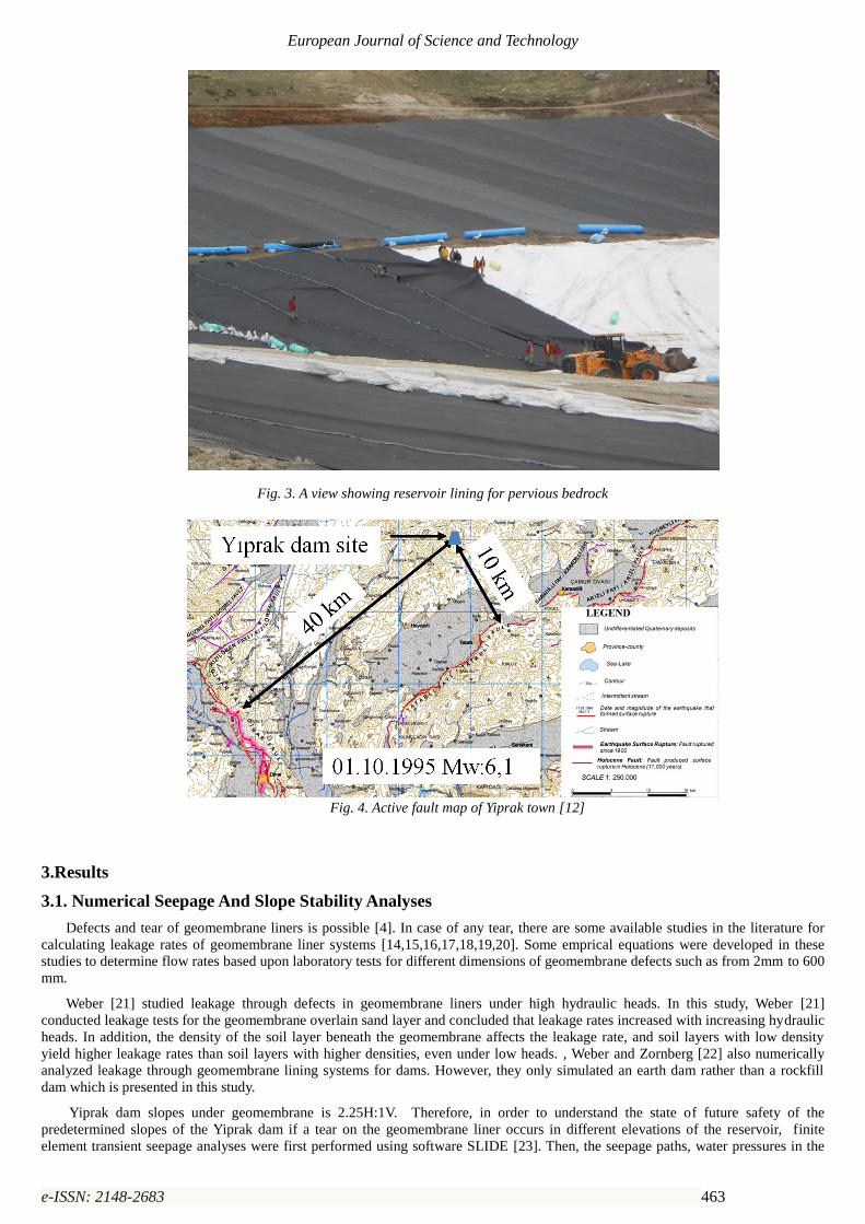
Two active faults close to the Yiprak dam site are available in the region. One is called Tatarlı fault almost 10 km far away the
location of the dam. The other is called Dinar fault almost 35 km far away the dam axis (Fig. 4)[12]. The maximum design
earthquake (MDE) was selected equal to the Maximum credible earthquake (MCE) which is defined as an upper bound of an expected
magnitude (Mw=6,1) for the site. An earthquake of such magnitude could produce 0.21g peak ground acceleration at the dam site
calculated by using the attenuation curves produced by Gülkan and Kalkan [13] for Tatarlı fault which is just 10 km far away the dam
site.
Page 4
European Journal of Science and Technology
e-ISSN: 2148-2683 463
Fig. 3. A view showing reservoir lining for pervious bedrock
Fig. 4. Active fault map of Yiprak town [12]
3.Results
3.1. Numerical Seepage And Slope Stability Analyses
Defects and tear of geomembrane liners is possible [4]. In case of any tear, there are some available studies in the literature for
calculating leakage rates of geomembrane liner systems [14,15,16,17,18,19,20]. Some emprical equations were developed in these
studies to determine flow rates based upon laboratory tests for different dimensions of geomembrane defects such as from 2mm to 600
mm.
Weber [21] studied leakage through defects in geomembrane liners under high hydraulic heads. In this study, Weber [21]
conducted leakage tests for the geomembrane overlain sand layer and concluded that leakage rates increased with increasing hydraulic
heads. In addition, the density of the soil layer beneath the geomembrane affects the leakage rate, and soil layers with low density
yield higher leakage rates than soil layers with higher densities, even under low heads. , Weber and Zornberg [22] also numerically
analyzed leakage through geomembrane lining systems for dams. However, they only simulated an earth dam rather than a rockfill
dam which is presented in this study.
Yiprak dam slopes under geomembrane is 2.25H:1V. Therefore, in order to understand the state of future safety of the
predetermined slopes of the Yiprak dam if a tear on the geomembrane liner occurs in different elevations of the reservoir, finite
element transient seepage analyses were first performed using software SLIDE [23]. Then, the seepage paths, water pressures in the
Page 5
European Journal of Science and Technology
e-ISSN: 2148-2683 464
embankment and amount of seepage at the downstream toe of the rockfill were calculated. Embankment water pressures due to the
rupture of the geomembrane were used in the stability calculations of the slopes of the rockfill dam.
In addition, for the case that the maximum credible earthquake hits the region, existing upstream and downstream slope safety of
the dam were also checked for partial (minimum water level) and full storage levels. In this case, bedrock acceleration, MCE of 0.21g
was also used as an average horizontal acceleration coefficient for sliding surfaces in limit equilibrium slope stability calculations.
The geometry of the section analyzed is seen in Fig. 3. Embankment and bedrock material properties as well as constitutive models
used in the analyses are given in Table 2. Yiprak rockfill strength parameters was determined using the relationships developed by
[24,25,26]. Since small scale laboratory tests do not always represent well field rockfill properties and conducting large scale rockfill
shear tests for each dam project is not practical, shear strength properties of rockfill embankments are usually determined depending
on past available data set obtained from different projects, site rockfill construction specifications (such as layer compaction
thickness, d50 particle size, density, porosity and roughness of the particles). For rockfill, cohesion is zero. However, drained internal
friction angle usually varies from 350 to 550 depending on the confining pressure, particle size (d50), particle breakage, gradation,
roughness and porosity of the particles [24,25,26].
Barton and Kjærnsli [25], also developed an Equation (Eqn 2 ) to calculate drained internal friction angle of rockfill.
Permeability value of geomembrane liner was taken 10−14 cm/s based on reported values in literature [4].
∅′ = 𝑅 𝑙𝑜𝑔 (𝑆
𝜎𝑛′ ) + ∅𝑏 (2)
where R : the porosity, 𝜎𝑛′ : vertical efective total rockfill stres , ∅𝑏: basic rockfill friction angle , S: equivalent strength.
Table 2. Yiprak embankment and bedrock material properties.
Slope stability analyses were performed using software SLIDE [23]. The factor of safety of the slopes were calculated by widely
used Bishop limit equilibrium method described in Eurocode 7 [27] by using Equation 3. Calculated safety factors of upstream and
downstream slopes along with transient seepage analyses for all three different scenarios are briefly given in Table 3. Case 1 in Table
3 represents full storage condition along with earthquake effect. Case 2 represents partial (minimum water level) storage with
earthquake acceleration. Case 3 is a seepage case due to a tear occurrence of geomembrane liner when reservoir is its maximum level.
Figures 5, 6 and 7 corresponds to the Cases 1 and 2. [28]
𝐹𝑆 =∑[(𝑐.𝑙+𝑊.𝑡𝑎𝑛∅){𝑐𝑜𝑠𝛼+
𝑠𝑖𝑛𝛼.𝑡𝑎𝑛∅
𝐹𝑆}]
∑ 𝑊.𝑠𝑖𝑛𝛼 (3)
where, W: Weight of each slice, l: Length of the failure surface of the slice, ∅: Internal friction angle of the material, c:
Cohesion of the material, α: Angle of the slice with horizontal and FS: Factor of safety.
Material property Geomembrane Sandy filter Rockfill Bedrock Sub-bedrock
c (kN/m2) - 0 0 0 0
∅’ (degree) - 38 40 45 52
(kN/m3) - 19 21 25 25
K (cm/s) 10-14 10-3 10-2 5x10⁻³ 10-4
Page 6
European Journal of Science and Technology
e-ISSN: 2148-2683 465
Table 3. Stability conditions
Cases Upstream slope safety (FS) Downstream slope safety (FS)
1 3.326 1.301
2 2.207 1.301
Time (Days) Downstream slope safety (FS) Discharge (m3/day)
3
200 1.827 0.001025
500 1.435 240.89
1000 1.388 240.28
2500 1.385 242.32
Fig. 5. Downstream slope safety factors of sliding surfaces for full and partial storage cases with 0.21g acceleration coefficient.
Fig. 6. Upstream slope safety factors of sliding surfaces for full storage case with 0.21g acceleration coefficient.
Page 7
European Journal of Science and Technology
e-ISSN: 2148-2683 466
Fig. 7. Upstream slope safety factors of sliding surfaces for partial storage case with 0.21g acceleration coefficient.
In case of leakage in the geoemembrane (Figure 8), numerical transient seepage analyses along with calculated stability safety
factors of the downstream slope of the dam are also presented in the following Figures, 9,10, 11 and 12.
As oppose to the downstream slope of the dam, upstream slope will not be a critical slope in terms of any sliding even if seepage
occurs due to a rupture on the geomembrane liner since high reservoir water pressure acting on the upstream geomembrane liner has
positive impact on the shear strength of the sliding surfaces. Therefore upstream slope safety was not taken into consideration in case
of leakages on the geomembrane defects.
As a result of transient numerical seepage analyses, it was observed that factor of safety value of the downstream slope
diminishes for each time period (time step) depending on the developed pressures in the pervious rockfill and bedrock. For instance,
in general, in the first step as the beginning of the leakage, safety factor of the downstream slope becomes higher. However, due to
development of seepage in the rockfill and pervious rock foundation, factor of safety value of the slope decreases and reaches its
minimum value at the end of the time step (steady state seepage condition). Numerical seepage analyses were performed using 2-D
Laplace seepage equation solved by finite element method (Eqn 4). In the modeling, 3 noded triangle elements were used. The
number of the elements was 1500. The number of time stages was 5 with the times, 50, 200, 500, 1000 and 2500 days. The maximum
number of the iteration was 100 and tolerance was 0.0001. The general governing equation is for transient seepage flow in a
heterogeneous and an isotropic soil [29].
𝜕
𝜕𝑥(𝐾𝐻
𝜕ℎ
𝜕𝑥) +
𝜕
𝜕𝑦(𝐾𝑉
𝜕ℎ
𝜕𝑦) + 𝑄′ =
𝜕𝜃
𝜕𝑡′ (4)
where, h: total head, KH and KV :Hydraulic conductivities in the horizontal and vertical dimensions, Q’: applied boundary flux, 𝜃:
volumetric water content, t’: time.
Since the risk of occurrence of a leakage due to a liner rupture and also a large earthquake at the same time is very low,
earthquake effect on the sliding surfaces in slope stability calculations was not taken into account in case of leakage. Seepage analyses
provided also amount and pressures of seepage at the downstream toe level of the dam. Numerical transient seepage analyses showed
that seepage amount and foundation seepage pressures at the downstream toe of the dam increase by time depending on the
development of the leakage from the geomembrane rupture and reach their maximum values at the end of the time step. It was also
observed that seeped water in the pervious bedrock caused high seepage pressures at the toe level of the dam. This foundation seepage
pressure was the largest one and reached 20 kPa value at the downstream toe of the dam wherein vertical rockfill pressure had also
almost same stress value. Therefore, in order to prevent any heave occurrence at the dam toe, it is recommended for this particular
dam to construct a downstream toe drain or a relief well.
Page 8
European Journal of Science and Technology
e-ISSN: 2148-2683 467
Fig. 8. Rupture location of the geomembrane liner
Fig. 9. Flow lines, pressure heads, seepage amount and safety factor of downstream slope in case of a geomembrane rupture when
the reservoir is in its maximum level (Starting leakage (time =200 days))
Fig. 10. Flow lines, pressure heads, seepage amount and safety factor of downstream slope in case of a geomembrane rupture when
the reservoir is in its maximum level (Starting leakage (time =500 days))
Page 9
European Journal of Science and Technology
e-ISSN: 2148-2683 468
Fig. 11. Flow lines, pressure heads, seepage amount and safety factor of downstream slope in case of a geomembrane rupture when
the reservoir is in its maximum level (Starting leakage (time =1000 days))
Fig. 12. Flow lines, pressure heads, seepage amount and safety factor of downstream slope in case of a geomembrane rupture when
the reservoir is in its maximum level (Starting leakage (time =2500 days - steady state condition))
4. Discussion
In this study, for safety of the Yiprak rockfill dam with geomembrane seepage barrier, findings are explained below:
Upstream and downstream slopes with 2.25H to 1V are sufficiently stable for full storage and partial storage conditions
even in case of a large earthquake causing 0.21g average horizontal acceleration on the sliding surfaces.
For the upstream slope, the lower sliding safety factors were obtained when the reservoir is at its minimum storage level
in case of earthquake with a seismic coefficient of 0.21g. However, sliding safety factors become the highest if the
reservoir is its highest level since the highest water pressures acting on the upstream slope face occur. Since then,
rockfill strength on the failure surfaces is increased due to the effect of reservoir water pressure.
Performing transient numerical seepage analyses is quite important to estimate the water pressures for different bedrock
or foundation soil conditions as well as to determine the effects on the water pressure and slope safety factor variations.
At the beginning of the seepage, it was observed that slope safety factors are usually higher since developed pore water
pressures in the rockfill are less. However, at the final stage which is the steady state condition, slope safety factors
become the lowest since then seepage pressures are the heighest.
Even in case of leakages, slopes of the dam will sufficiently be safe.
Page 10
European Journal of Science and Technology
e-ISSN: 2148-2683 469
In case of a geomembrane liner puncture, It is recommended for this particular dam case that constructing a downstream
toe drain or a relief well will provide a safety measure against any heave occurrence or instability of the rockfill toe
since the embankment and bedrock foundation are quite pervious causing high seepage pressures.
5. Conclusion
The slopes of Yiprak dam are safely designed. If a rupture occurs on the geomembrane liner when the storage is full, slopes of the
dam will still perform well and slopes will be safe against any failure. It is very important to perform transient numerical seepage
analyses beside slope safety analyses to understand the development of seepage paths, prediction of pore water pressures and amount
of seepage at the downstream part of the dam in case of any tear onthe geomembrane liner. It is also recommended that numerical
transient seepage analyses should be performed to assess slope safety of the dam for different embankment types and embankment
and foundation material properties.
References
[1] Koerner , R. M., & Wilkes, J. A. (2012). 2010 ICOLD Bulletin on Geomembrane Sealing Systems for Dams. Geosynthetics.
[2] ICOLD. (2010). Geomembrane Sealing Systems for Dams - Design Principles and Return of Experience.Bulletin 135. France.
[3] ICOLD. (2011). Small Dams-design, Surveillance and Rehabilitation. International Commission on Large Dams, Bulletin 143.
France.
[4] Bhowmik, R., Shahu, J., & Datta, M. (2017). Failure analysis of a geomembrane lined reservoir embankment. Geotextiles and
Geomembranes, vol. 46, p. 52-65.
[5] Poulain, D., Peyras, L., & Meriaux, P. (2011). Feedback and guidelines for geomembrane lining systems of mountain reservoirs in
France. Geotextiles and Geomembranes, Vol. 29, p. 415-424.
[6] Mendoza, C., Gisbert, A., Izquierdo, A., & Bovea, M. (2009). Safety factor nomograms for homogeneous earth dams less than ten
meters high. Engineering Geology, vol. 105, p. 231-238.
[7] Tolooiyana, A., Abustana, I., Selamata, M., & Ghaffari, S. (2009). A comprehensive method for analyzing the effect of geotextile
layers on embankment stability. Geotextiles and Geomembranes, Vol.27, p. 399-405.
[8] Briancon, L., H., G., & D., P. (2002). Slope stability of lining systems- experimental modelling of friction at geosynthetic
interface. Geotextiles and geomembranes, Vol. 20, P. 147-172.
[9] Earth, G. (2019). 3 3, 2019 tarihinde Google Earth: http://www. google.com.tr/int/tr/earth adresinden alındı
[10] Erlingsson, S., & Hauksson, D. R. (2009). Analysis of a geomembrane face rockfill dam during earthquake loading. Proceedings
of the 17th International Conference on Soil Mechanics and Geotechnical Engineering, p. 1678-1681.
[11] Jones, D. R., & Dixon, N. (2003). Stability of Landfill Lining Systems: Report No. 1. R&D Technical Report P1-385/TR1.
Research Contractor: Golder Associates (UK) Ltd. In conjunction with Loughborough University Consultants Ltd.
[12] MTA-Turkey. (2016). Dinar active fault map. http://www.mta.gov.tr/v2.0/default.php?id=yeni_diri_fay_haritalari:
http://www.mta.gov.tr/v2.0/default.php?id=yeni_diri_fay_haritalari adresinden alınmıştır
[13] Gülkan, P., & Kalkan, E. (2002). Attenuation modeling of recent earthquakes in Turkey. Journal of Seismology, Vol. 6, p. 397-
409.
[14] Giroud, J. a. (1989). Leakage through liners constructed with geomembranes – Parts I and II. Geotextiles and Geomembranes,
8(1-2), p. 27-67 and 71-111.
[15] Giroud, J. P. (1997). Equations for calculating the rate of liquid migration through composite liners due to geomembrane defects.
Geosynthetics International, Vol. 4(3-4), p. 335-348.
[16] Foose, G. J., Benson, C. H., & Edil, T. B. (2001). Predicting leakage through composite landfill liners. Journal of Geotechnical
and Geoenvironmental Engineering, ASCE, Vol. 127(6), p. 510-520.
[17] Touze-Foltz, N., & Giroud, J. P. (2005). Empirical equations for calculating the rate of liquid flow through composite liners due
to large circular defects in the geomembrane. Geosynthetics International, Vol.12 No.1, p. 205-207.
[18] Girard, H., Fischer, S., & Alonso, E. (1990). Problems of friction posed by the use of geomembranes on dam slopes-examples
and measurements. Geotext. Geomembranes, Vol. 9, p. 129-143.
[19] Wu, W., Wang, X., & Aschauer, F. (2008). Investigation on failure of a geosynthetic lined reservoir. Geotexit and Geomembranes,
Vol. 26, p.363-370.
[20] Moraci, N., Cardile, G., Gioffrè, D., Mandaglio, M. C., Calvarano, L. S., & Carbone, L. (2014). Soil geosynthetic interaction:
Design parameters from experimental and theoretical analysis. Transportation. Infrastructure. Geotechnology., p. 165-227.
[21] Weber, C. T. (2008). Leakage through defects in geomembrane liners under high hydraulic heads. Texas: The University of Texas
at Austin.
[22] Weber, C. T., & Zornberg, J. (2008). Numerical analysis of leakage through geomembrane lining systems for dams. The First Pan
American Geosynthetics Conference & Exhibition. Cancun, Mexico.
[23] SLIDE. (2010-2016). Comprehensive slope stability analysis software. Rocscience Inc., 39 University Ave Ste 780 Toronto,
Ontario M5G 1Y8.
[24] Leps, T. (1970). Review of the shearing strength of rockfill. J. of Soil Mech. and Found. Div., Vol. 96(SM4), p. 1159-1170.
[25] Barton, N., & Kjærnsli, B. (1981). Shear strength of rockfill. J. of the Geotech. Eng. Div., Vol. 107(GT7), p. 873-891.
[26] Marachi, N. D., Chan, C. K., & Seed, H. B. (1972). Evaluation of properties of rockfill materials. J. Soil Mech. Found. Div., Vol.
98(SM1), p. 95-114.
[27] Eurocode, 7. (2013, June 13-14). Geotechnical Design. Dublin.
Page 11
European Journal of Science and Technology
e-ISSN: 2148-2683 470
[28] Bishop, A. W. (1955). The Use of the slip circle in the stability analysis of slope. Geotechnique, Vol. 5, P. 7-17.
[29] Charbeneau, R. J. (2000). Groundwater .hydraulics and pollutant transport. New Jersey: Prentice Hall.