Electrical and Instrumentation Department Thapar Institute of Engineering and Technology
Patiala, Punjab (147004), India.
Surya Prakash
Electrical and Instrumentation Department Thapar Institute of Engineering and Technology
Patiala, Punjab (147004), India
Abstract
For the power system stability enhancement, designing and performance analysis of the Flexible AC Transmission System devices has been presented in this paper for an 11kv system. Devices like Thyristor Controlled Series Capacitor, Fixed Capacitor Thyristor Controlled Reactor and Static Synchronous Compensator are designed for the purpose of system stability and continuous power flow in the system. The idea of the paper is to compare the power profile of the system under different conditions and system parameters which is variable capacitor values (50µF - 1500µF). The power profile and characteristics of the uncompensated system with the system with compensating devices has been shown. Also, the fault analysis for the statcom compensated system analyzing the effect of fault on the system has been studied. The detailed analysis of results, based on performance and economics, device for the real and reactive power flow improvement, enhancing the system stability shows statcom compensated device to be better than the other compensating devices.
Keywords: Power Profile, Voltage Profile, Stability, Economics, FACTS, Uncompensated system, TCSC, FC-TCR, STATCOM.
INTRODUCTION
Due to the complication in the present power system, it is very much important to fulfill the consumer demand with the finest possible power quality and the power factor [1]. As the increasing price and environmental effects of the conventional fossil fuels now a day’s focus has shifted towards the renewable energy resources [2-4]. But due to the these renewable energy resources, increase in the network complexity, more system operation and control is required, which is another big challenge for the system [5-8], but with the introduction of various types of RES in the electricity network like wind and solar, FACTS technology proves to be helpful in many ways [9-10].
The major factor that must remain the same is the steady state stability of the system along with the power quality in the network [11-13]. By the use of highly modern and developed techniques, the system thus needs to be made more reliable and secure, resulting in better power quality. To serve such purpose in the modern world the use of Flexible AC
Transmission System (FACTS) devices needs to be enhanced such that the technology results in improved the quality of power, voltage stabilization, power factor improvement, and damping of harmonics [13-17]. Also with the rise in the consumer demand it has become necessary to construct new power stations and to have new transmission lines, but it also raises the power system operation and control issues along with the overall capital cost of such construction and maintenance cost [18]. The reduction in the system margin due to limitation in regulation increases the chances of voltage collapse and frequency drop of the system [19]. Some of the reasons for voltage collapse of the system include the overloading of the system, severe faults, sudden increase in the load and the rise in the reactive power demand and hence the inability of the system to inject enough reactive power results in the unstable system and system collapse [20]. Many a times due to the fault in the system, there is a mismatch of reactive power, also the variation of the load at the consumer end causes such imbalance in the system [21]. Hence, to recover from such condition it is necessary to supply the reactive power to the system as according to the necessity. To balance the power of the system mainly the reactive power, linking of FACTS devices with the line can be useful for the electrical system [22].
FACTS are the devices that are capable of providing such flexibility to the system reactive power demand. It is one of the most important reactive power sources. FACTS may be defined as a power electronic based semiconductor device which can supply or absorb reactive power in a system as per requirement. Thus, by the use of FACTS devices, the stress on the power system can be eliminated. In addition to above major factors discussed the FACTS devices like static synchronous compensator, thyristor controlled series capacitor along with fixed capacitor thyristor controlled reactor are also capable of improving the steady state condition i.e. the transient condition. Thus the other solution for the increasing power transmission without any loss in the form of power quality can be FACTS technology [23]. For the development of HVDC transmission system, the whole system has been transferred from conventional controllers to power electronics based controllers for providing better power flow and stability of the whole system. The major types of controllers available in the FACTS controllers are of 4 types which are series controller, shunt controllers, series-series controller and series-
Performance Evaluation of FACTS Controllers for Short
shunt controllers. The power flow of the line or the system by series controller is done by injection of line voltage in series. This injection of voltage is controlled directly by the controllers which are dependent upon the value of capacitor and reactors thus control of power can be done, whereas the shunt controllers are used for damping of oscillation [24].
By applying FACTS controllers into the system gives a number of advantages over an uncompensated system like giving better voltage stability, reducing the power losses, improving the power profile of the system, power system security, power quality improvement, increase in the capacity of the transmission line to carry more power along with voltage regulation of the system [25]. The use of FACTS devices for improvement in the power profile along with voltage, current for the enhancement of the system have been studied in [26]. For the control of dynamic nature of the voltage of the system STATCOM can be installed in both transmission and distribution [27]. By the use of STATCOM for improvement in the power quality, thus limiting the system to still use fixed speed generator which gives minimum cost and less maintenance [28]. For the system to be in a stable state and provide reactive power compensation along with the control of voltage and power flow the optimal location of the devices have been discussed in [29]. The quality of power depends upon the supplier. Due to drop in quality of the supply the system feels flickering in the system such that there is a need of the FACTS devices to balance this state such that to enhance the power quality and thus the stability [30-32].
Major Categories of modern FACTS controllers:
1. Series-Series controller: For achieving better performance in a controlled and coordinated manner, the combination of different FACTS devices is done. The advantage of such combination of the series devices is the utilization of the strengths of different devices upcoming their drawbacks for more stability. Example of series-series controller: IPFC
2. Series-Shunt controller: Similar to the series-series combination, various shunt connected devices can also be combined with the series devices in connection with the power system. Such combination can be used for a line where both the current and voltage needs to be injected or absorbed such that for increasing the stability of the system. Example of series-series controller: UPFC, IPFC etc.
3. Shunt controller: For the injection or absorption of current in the power system, shunt connected FACTS devices are used. Example of series-series controller: TCSC, TCPAR and SSSC,
4. Series controller: The main principle of using series connected FACTS device is injection or absorption of the voltage in series with the main transmission line for the better reactive power control. Example of series-series controller: STATCOM and SVC.
FACTS DEVICES
FIXED CAPACITOR THYRISTOR CONTROLLED REACTOR
SVC or the Static VAR compensators are the oldest in the FACTS controllers’ family used for the improvement of the overall system by the improvement of voltage regulation and power flow in the system. The other benefits of SVC include dynamic voltage problems can be solved along with reduction in system losses and also the control feature of the controller.
Significance of SVC controller
A. Increased performance rate in steady state.
B. Decrease in system losses.
C. System power flow control.
D. Transient voltage stability control.
In Figure 1. Fixed Capacitor Thyristor Controlled Reactor is shown with parallel connection of the variable capacitor with the TCR. Is, Ir and Ic are system current, reactor current and current flowing through capacitor of the device. The main objective of applying FCTCR into the system is to provide continuous power flow in terms of VAR to the system. This VAR can be either lagging or leading. By the control of the firing angle of thyristor, Ir i.e. the current flowing through the reactor can be easily controlled. To provide the leading VAR the capacitor values are varied such that the system stability and quality of power must also get improved and in case of giving lagging VAR to the system the thyristor controlled reactor is taken to be of much larger value than the capacitor value.
The authors in [33], discusses the power system with eight buses and in connection with FC-TCR. The designed and simulated system shows the reactive power control and its benefits to the power system. Also, in [34], shows the detailed simulation of FC‐ TSR‐ TCR system and its advantages to the connection with the power system.In [35], the detailed study of voltage stability and the non‐ sinusoidal quantities under the PQ criteria have been done. The work aims towards the harmonics and voltage stability in the power system in connection with the TCR. Thus, the harmonics generated via electronic devices and in SVC with TCR and the effects of harmonics on Small Signal Voltage Stability are examined for various operational conditions.
For the purpose of power oscillation damping, in [36] various auxiliary signals have been studied. These signals may be a deviation in active and reactive power to TCR‐ FC bus, frequency deviation, derivative of active power, reactive power etc. The simulation and design of TCR with GTO controlled series capacitor for the series compensation of transmission power system have been shown in [37]. For voltage stability, in [38], by using the combined FC-TCR, the issues related to variation in reactive power, frequency and the small signal voltage stability have been analyzed.
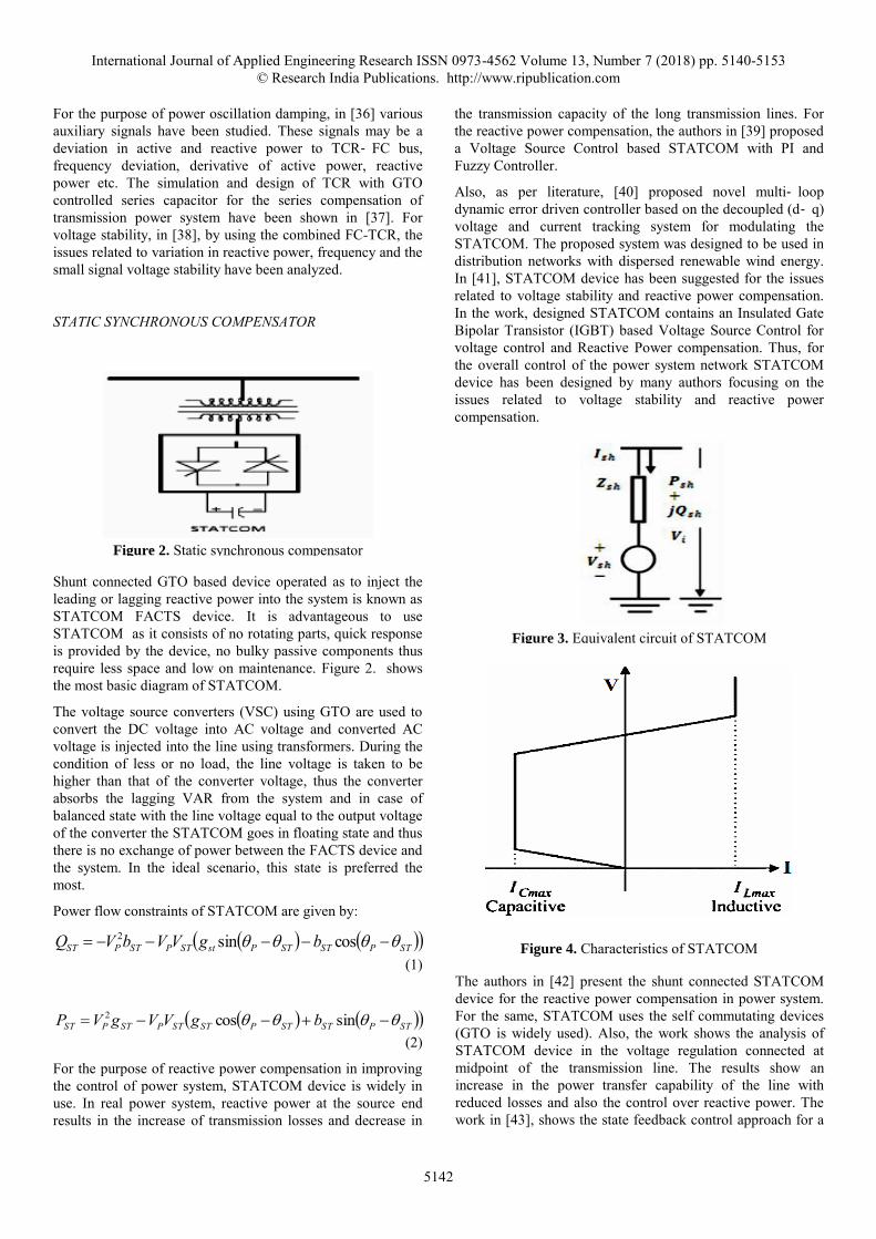
STATIC SYNCHRONOUS COMPENSATOR
Shunt connected GTO based device operated as to inject the leading or lagging reactive power into the system is known as STATCOM FACTS device. It is advantageous to use STATCOM as it consists of no rotating parts, quick response is provided by the device, no bulky passive components thus require less space and low on maintenance. Figure 2. shows the most basic diagram of STATCOM.
The voltage source converters (VSC) using GTO are used to convert the DC voltage into AC voltage and converted AC voltage is injected into the line using transformers. During the condition of less or no load, the line voltage is taken to be higher than that of the converter voltage, thus the converter absorbs the lagging VAR from the system and in case of balanced state with the line voltage equal to the output voltage of the converter the STATCOM goes in floating state and thus there is no exchange of power between the FACTS device and the system. In the ideal scenario, this state is preferred the most.
Power flow constraints of STATCOM are given by:
STPSTSTPstSTPSTPST bgVVbVQ cossin2
(1)
STPSTSTPSTSTPSTPST bgVVgVP sincos2
(2)
For the purpose of reactive power compensation in improving the control of power system, STATCOM device is widely in use. In real power system, reactive power at the source end results in the increase of transmission losses and decrease in
the transmission capacity of the long transmission lines. For the reactive power compensation, the authors in [39] proposed a Voltage Source Control based STATCOM with PI and Fuzzy Controller.
Also, as per literature, [40] proposed novel multi‐ loop dynamic error driven controller based on the decoupled (d‐ q) voltage and current tracking system for modulating the STATCOM. The proposed system was designed to be used in distribution networks with dispersed renewable wind energy. In [41], STATCOM device has been suggested for the issues related to voltage stability and reactive power compensation. In the work, designed STATCOM contains an Insulated Gate Bipolar Transistor (IGBT) based Voltage Source Control for voltage control and Reactive Power compensation. Thus, for the overall control of the power system network STATCOM device has been designed by many authors focusing on the issues related to voltage stability and reactive power compensation.
The authors in [42] present the shunt connected STATCOM device for the reactive power compensation in power system. For the same, STATCOM uses the self commutating devices (GTO is widely used). Also, the work shows the analysis of STATCOM device in the voltage regulation connected at midpoint of the transmission line. The results show an increase in the power transfer capability of the line with reduced losses and also the control over reactive power. The work in [43], shows the state feedback control approach for a
single infinite bus Machine connected with a STATCOM. Also, in [44], low rating STATCOM for the consumer end was proposed for better control over the electric power system. The proposed STATCOM is designed with cascading full‐ bridge Voltage source inverters with PCC (point of common coupling). Thus, allowing the compensation of required reactive current at the consumer load end and the midway harmonics present in the system. As per the authors in [45] voltage source converter based STATCOM has been purposed for the better voltage regulation in transmission and distribution systems. The ability of the STATCOM FACTS device of supplying dynamic VARs required at the time of system faults for voltage support has been considered. In work, by the purposed VSC based STATCOM device, effect of supplying or absorbing of the reactive power on the apparent impedance has been analyzed aiming towards the working of distance relays. In [46] various applications and advantages of the STATCOM FACTS device with SVC have been discussed. The focus of the work is on STATCOM device for the improved power quality of grid integrated with wind power. Various other features and advantages of using the STATCOM device in the improvement of power system have also been reviewed. In [47], FACTS devices in coordination with the power system for stable operation of the complete system along with the reduction in losses and increased power transfer capability has been studied and reviewed. The control over power flows in the existing power system is a major requirement for a stable system. The work in [48] with STATCOM connected in shunt with the transmission line for control of voltage and thus the power flow has been presented. According to another author in [49] nonlinear operation of STATCOM has been presented. The analysis of the work shows nonlinear controller with better performance than the linear controllers.
THYRISTOR CONTROLLED SERIES CAPACITOR
With the special feature that the thyristors with gate turn off capability not required TCSC is an important series compensator in the FACTS device family. It is positioned in series with the main transmission line as shown in Figure 5. The capacitor and a reactor are required for the control of the power. In series with the line, capacitor of variable value is fixed and the TCR is placed in parallel to the capacitor.
The economics of the system is improved by using TCSC as the insertion of capacitor results in elimination of the use of HV transformer. But the constraint of using TCSC in the system is the use of high value of capacitor as at low value the results may come out to be non-satisfactory.
For a constant value of capacitance,
t
C
CT
xx
jxx
1
(3)
For the optimal power system planning and control, modern FACTS technology has to be considered. The issue related to the control of reactive power flow has been resolved using modified PSO. The automatic adjustment of the TCSC FACTS device in coordination with voltages of the generating units is done using the proposed algorithm [50].
TCSC being used as the multi objective tool in power systems has its application in the voltage stability of the power system. By varying the reactive power of the system, the voltage of the connected system can be stabilized. In the literature, the effect of connecting TCSC with power system for the purpose of small signal voltage stability has been well discussed [51].
For identification of the best location for connecting the TCSC, line stability index has been considered as per [52], under accepted lines outage contingencies. For the purpose of voltage stability, the FACTS device is incorporated in the purposed Newton Raphson load flow algorithm. For the damping characteristic improvement, in [53] an output feedback variable structure controller has been proposed. The input to the proposed controller is the actual and the real power at the point of TCSC. These input signals are used to build the switching hyper plane for the proposed TCSC controller. The automatic control scheme for the working model has been developed in [54] – [55]. The analysis of the TCSC connected system for synchronous stability and voltage stability is done using the P‐ δ and P‐ V Curves which show improved results when compared with the literature. For determining the available power transfer capacity, TCSC have been used in [56]. The loading limits of the thermal units are considered as the constraints of the proposed work. Also, the maximum and minimum of the transfer capacity of the thermal unit are calculated using Power Transfer Distribution Factor. The challenges of increasing power transfer capacity in power system have been discussed in [57].
As per the literature, the issue of power system stability improvement with TCSC controller, modifying the design of the coordinates has been shown in [58]. It uses the PSO
technique, optimizing the parameters of FACTS devices constrained to nonlinear optimization problem. Similarly, the authors in [59], using the genetic algorithm analyzing the sensitivity and optimum setting of the TCSC device have proposed the new method. Thus, aiming towards the optimal location and setting of TCSC.
OBJECTIVE AND MOTIVATION
The foremost aim of this paper is to study the performance of various FACTS devices in the 11kv system with same system configuration. On the basis of performance, the comparison between uncompensated and compensated devices has been done. The other part of the paper shows the performance analysis of the system and the device under fault and after the clearance of the fault. The overall preference of the FACTS device is hence dependent on the performance characteristics along with the economy factor.The problem of economics due to mismatch of the device and the system configuration along with the preference that has to be given to the device on the basis of their performance analysis is the main motivation of this paper.
PERFORMANCE ANALYSIS OF SYSTEM WITH FACTS DEVICES
Uncompensated Power System
The below model created by using MATLAB Simulink software shows an uncompensated system with 11KV of source voltage and a constant load of 25MW and 50MVAR. The basic model, shown in Figure 7 consists of various measurements block available in the Simulink library with real and reactive power measurement block too. As from [4] the test system configuration with 11KV of source voltage and constant load of 25MW, 50MVAR includes source impedance of (0.01+j0.001) Ω, Line impedance of (5+j0.023) Ω. The various measurement blocks like current measurement block measures the instantaneous value of the source as well as load current of the system. In the similar manner the voltage measurement block gives the source and load voltage of the system.
The results of the current and voltage measurement block can be seen using the scope and the value of Is IL Vs VL is displayed through the display block. The PQ block or the real
and reactive power measurement block is used to measure the real and reactive power of the system on the load side. The model in the Figure 7. display each value that is required for the analysis of the uncompensated system. Below are the simulation results of the system showing obtained power flows, load voltage and the load current:
The above results show the load voltage to be 2.514KV along with the Real and reactive power flow without adding any compensating device. By the injection of reactive power in the system the system stability, which is considered to be an
important factor can be maintained. By the use of various compensating devices to provide system stability and thus better performance various devices have been presented in this paper. Based on the assessment of the system with various devices, the device with better performance will be decided. The system with the compensating devices is tested for various capacitor values ranging from 50 µF – 1500 µF.
Compensated Power System
Fixed Capacitor Thyristor Controlled Reactor compensated Model
For 11k line the compensated model for the Fixed Capacitor- TCR model is shown in Figure12.
The load and the impedance for the system is 25MW, 50MVAR and (0.01+j0.001) Ω. In Figure13. to Figure16., results for the system configuration of Figure12. have been discussed.
Table 1: Variation of power flow with change in capacitance
Sr. no. Capacitance
(µF)
Real power
(MW)
Reactive power
(MVAR)
1. 50 11.71 23.43
2. 100 12.05 24.11
3. 200 12.76 25.52
4. 500 15.06 30.11
5. 750 17.09 34.18
6. 1000 19.05 38.10
7. 1500 21.89 43.38
The table1 clearly shows the variation in the system power flows with the change in the capacitor value. At the maximum value of capacitor the real and the reactive power are maximum and decrease with the decrease in the capacitive value.
Static Synchronous Compensator compensated Model
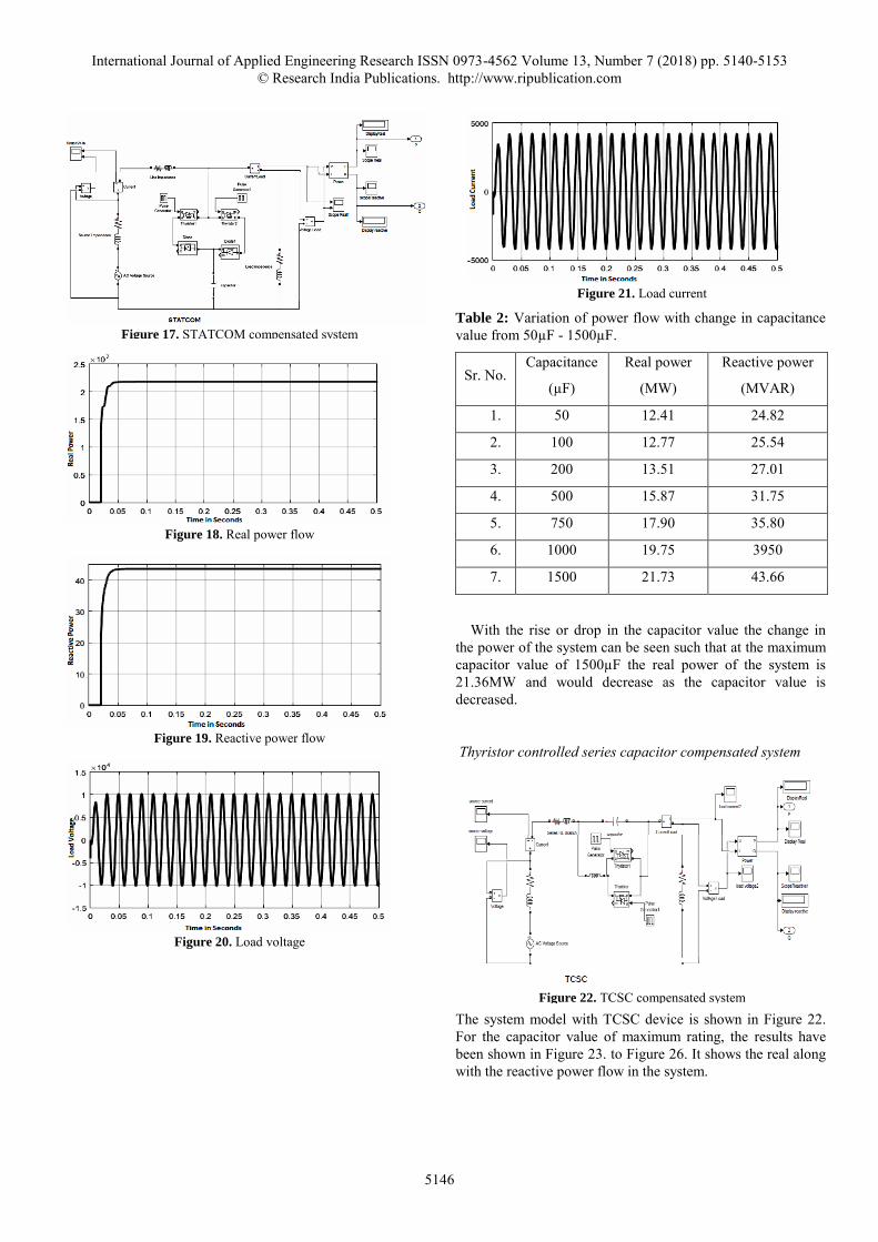
The STATCOM compensated system with the same configuration has been shown in Figure17. The capacitor placed in shunt with the line must be varied to get the change in the power flow level of the system. The simulation results for the STATCOM compensated device are given in Figure 18 to Figure 21 representing real power, load voltage and current and also the reactive power of the system. Whereas the variation in the flow of real and reactive power with respect to the change in capacitor value can be seen in Table 2.
Table 2: Variation of power flow with change in capacitance value from 50µF - 1500µF.
Sr. No. Capacitance
(µF)
Real power
(MW)
Reactive power
(MVAR)
1. 50 12.41 24.82
2. 100 12.77 25.54
3. 200 13.51 27.01
4. 500 15.87 31.75
5. 750 17.90 35.80
6. 1000 19.75 3950
7. 1500 21.73 43.66
With the rise or drop in the capacitor value the change in the power of the system can be seen such that at the maximum capacitor value of 1500µF the real power of the system is 21.36MW and would decrease as the capacitor value is decreased.
Thyristor controlled series capacitor compensated system
The system model with TCSC device is shown in Figure 22. For the capacitor value of maximum rating, the results have been shown in Figure 23. to Figure 26. It shows the real along with the reactive power flow in the system.
The Figure 25 and Figure 26 shows the voltage and the current at the load side such that the magnitude of the voltage must be in accordance to the sending end voltage of the stable system.
TCSC compensated system with a higher capacitor rating shows better performance and the improvement in the stability level. For various values of the capacitor the ranging from 50µF to 1500µF, table3 shows the simulated change in the power level of the system.
Table 3: Variation of power flow with change in capacitance
Sr. No. Capacitance
(µF)
Real power
(MW)
Reactive power (MVAR)
1. 50 0.63 1.17
2. 100 0.91 1.69
3. 200 1.57 3.14
4. 500 3.19 6.38
5. 750 8.23 16.47
6. 1000 12.86 25.71
7. 1500 16.65 33.29
Thus, it can be observed that by increasing the value of capacitor continuous compensation of real and reactive power can be done without any drop. Also the voltage profile improves up to a certain point, depending on capacitance value.
COMPARISON OF FACTS DEVICES
From the observation, it is seen that with the variation in the capacitance value significant improvement is present in all three systems. For the real power, STATCOM for the capacitor value of 500μF is preferred and at capacitor value of 1500μF, FC-TCR gives improved performance, whereas for reactive power STATCOM gives better performance than the other two devices. It must be noted that the rise in the value of capacitor gives consequent rise in the cost of the capacitor, thus for the system to be purely economical the cost constraint is an important factor for the designing of the system.
Table 4: Power Flow comparison of devices for various capacitor values
Device Real power Reactive power
Capacitor value
(µF)
50 500 1500 50 500 1500
FC-TCR 11.71 15.06 21.89 23.43 30.11 43.38
STATCOM 12.41 15.87 21.73 24.82 31.75 43.66
TCSC 0.63 3.19 16.65 1.17 6.38 33.29
Thus, from the Table 4 it can be concluded that the STATCOM device is much more suitable for the purpose of compensation than the other devices as comparatively the performance of the device is better along with the economic constraint STATCOM can be preferred with the capacitor value of 500µF or even 1000µF.
For the various devices discussed above in this paper, the overall results have been plotted in this section. Variation in the power profile with the change in capacitor value for FCTCR, STATCOM and TCSC are shown in Figure 27 to Figure 32.
Fixed Capacitor Thyristor Controlled Reactor type SVC compensation
For the FC-TCR compensated system model the real and reactive power flows for the capacitor value of 500µF, 1000 µF and 1500 µF have been shown in the above Figure 27 and Figure 28.
Static Synchronous Compensator Compensation
For the most preferred device of all, STATCOM compensated system shows the significant rise in the real and reactive power for the given system. The value of real power at the maximum value of 1500µF comes out be nearly 21.73MW, more than in comparison with the other devices.
Figure 29 and Figure 30 shows the change in the power flows with change in the value of shunt connected capacitor in the system. The STATCOM is preferred over the other devices because of its various advantages and better performance.
Thyristor controlled series capacitor Compensation
The graph shows the power flow of the power system for the changing value of the capacitor when a TCSC is connected to it. The rise in the value of capacitor results in the improvement in the system performance along with the system stability but relatively the cost of the capacitor and other components of the system is a constraint that is required to be achieved.
Figure 27. Variation of Real power flow with change in
capacitance (50-1500μF)
Figure 29. Variation in the real power flow with adjustment in
capacitance (50-1500μF)
Figure 28. Variation of Reactive power flow with change in capacitance (50-1500μF)
Figure 30. Variation of reactive power flow with change in
capacitance (50-1500μF)
Figure 31. Variation of real power flow with change in
The Figure 33 and Figure 34 shows the real and reactive power flows of all the various devices for same rating of capacitor and the system configuration. For high value of the capacitance the Fixed Capacitor-TCR system is considered to be better than the others, but is not proffered as it offers high capital investment in the system.
Whereas, if the overall performance for the various values of capacitance is considered than the STATCOM device has to be considered as it gives most suitable results at even lower values of the capacitance.
Case Study
In case of the occurrence of fault in the compensated system the system must respond to it in such a way that the system stability must be maintained and the compensation provided by the STATCOM device must remain constant after the clearance of the fault.
Figure 35 shows the faulty system with STATCOM connection. The use of the single phase breaker is assumed to be a kind of fault activated externally. This case study is to analyze the response of the system and the device in the fault condition. The results are simulated similarly for various values of capacitor, but for a specific value i.e.1500µF and are given by Figure 36 and Figure 37.
Figure 36. Real power flow
Figure 32. Variation of reactive power flow with change in
capacitance (50-1500μF)
Figure 33. Variation of real power flow between above FACTS
devices with change in capacitance (1500μF)
Figure 34. Variation of reactive power flow between above
The results above shows the real and reactive power flows before, in the presence and after the clearance of the fault. It is to be noted that the system stability must be regained. Thus, from the above analysis, it can be seen that after the fault have occurred there is a significant drop in the voltage, current and the power of the system, but after the clearance of the fault the real and reactive power that was required to be compensated remains the same and the system stability remains in a healthy state.
SUGGESTIONS FOR FUTURE DEVELOPMENTS
In this paper as the focus is on the three major devices in the FACTS family: STATCOM, TCSC and FCTCR, such that on the terms of their performance and the economic analysis the comparative study has been done. But this work can be carried out in the future for other devices like UPFC, IPFC or any other series connected device. In the modern world with the rise in technology a new series device GCSC (Gate Controlled Series Capacitor) has been introduced where the shunt capacitors are better for the power factor correction and reactive power support series capacitor used in GCSC can be useful for the control of voltage and the power loss reduction in the network [60]. Hence the gate controlled device GCSC can prove to be another option for the improvement in the power quality and power factor. Some of the advantages for the GCSC over the classical TCR are given below:
Table 5: Comparison of new and conventional devices
GCSC TCR
Switches are in parallel with the capacitor.
Switches are in series with the reactor.
The main supply is the current source.
The main supply is the voltage source.
The current of capacitor is controlled.
The voltage of the main reactor is controlled.
Voltage of the device controlled by blocking the angle of switches.
Current of the device controlled by the control of the firing angle.
All the switches are fired or blocked with zero voltage.
Blocking or firing of switches with zero current.
Hence, for the future study the analysis of such devices which have the ability to result in better, electrical network can be studied and the basis of the analysis may vary such that the aim of the research can be shifted towards the quality of power or the harmonics mitigation.
CONCLUSION
By the use of the MATLAB Simulink environment relative study of various FACTS devices: FC-TCR, STATCOM and TCSC associated with a short transmission line and its analysis along with thorough comparison have been done. Improvement in the voltage profile of the system, increase in the system stability and power flow improvement can be seen. From the observation table for FC-TCR and STATCOM compensated system, power flow get better proportionally with the variation or specifically rise in the capacitance value from 50µF - 1500µF. For the TCSC compensated system, high capacitance is required as at low values of capacitor TCSC is not preferred. The performance of the system under compensation has been analyzed such that, STATCOM gives optimum performance at the capacitor value of 500μF when the economic constraint is also included. FC-TCR type SVC compensates the system by the variation in the capacitor value of the range starting from very low to very high. The most preferred and highest value of power flow is achieved at the maximum capacitance value of 1500µF. Also TCSC, in the similar way gives better performance at the capacitor value of the order of 1500µF. But with the increase in the value of the capacitor will result in the rise in cost of equipment and thus the overall cost of the system. Thus the STATCOM device provides the best performance when connected to the system along with the economic constraint as compared to the other 2 devices. From the case study, where the fault state analysis gives the result in the favor of the STATCOM device as it maintains the stability of the system in the healthy state has been done. Also a glimpse of the future aspects of the power system quality and overall improvement devices like GCSC which is gate controlled series capacitor is given.
[1] CIGRE, “FACTS Overview”, IEEE Power Engineering Society, 95 TP 108, April 1995.
[2] A. M. El-Zonkoly, "Renewable energy sources for complete optimal power system black-start restoration," in IET Generation, Transmission & Distribution, 9(6), pp. 531-539, April 2015.
[3] M. H. Barmayoon, M. Fotuhi-Firuzabad, A. Rajabi-Ghahnavieh and M. Moeini-Aghtaie, "Energy storage in renewable-based residential energy hubs," in IET Generation, Transmission & Distribution, 10(13), pp. 3127-3134, June 2016.
[4] W. Sheng, K. y. Liu, Y. Liu, X. Ye and K. He, "Reactive power coordinated optimization method with renewable distributed generation based on improved harmony search," in IET Generation, Transmission & Distribution, 10(13), pp. 3152-3162, October 2016
[5] Y. Y. Zhang, R. Wang, T. Zhang, Y. Liu and B. Guo, "Model predictive control-based operation management for a residential micro grid with considering forecast uncertainties and demand response strategies," in IET Generation, Transmission & Distribution, 10(10), pp. 2367-2378, July 2016.
[6] F. M. Camilo, R. Castro, M. E. Almeida and V. F. Pires, "Self-consumption and storage as a way to facilitate the integration of renewable energy in low voltage distribution networks," in IET Generation,
Transmission & Distribution, Vol. 10, No. 7, pp. 1741-1748, May 2016.
[7] S. S. Sharma, S. Bhattacharjee and A. Bhattacharya, "Grey wolf optimization for optimal sizing of battery energy storage device to minimize operation cost of micro grid," in IET Generation, Transmission & Distribution, 10(3), pp. 625-637, February 2016.
[8] A. Fazeli, M. Sumner, M. C. Johnson and E. Christopher, "Real-time deterministic power flow control through dispatch of distributed energy resources," in IET Generation, Transmission & Distribution, vol. 9, no. 16, pp. 2724-2735, December 2015.
[9] K. Prashant, "Enhancement of Power Quality by an Application FACTS Devices," in International Journal of Power Electronics and Drive Systems, Vol. 6, No. 1, pp. 10-17, March 2015.
[10] M. Fadaee M., Radzi M.A.M., "Multi-objective optimization of a stand-alone hybrid renewable energy system by using evolutionary algorithms: a review, " in Renewable Sustainable Energy Reviews, 16(5), pp. 3364–3369, June 2012.
[11] F. Blaabjerg, Chen Z., Kjaer, S.B., ‘Power electronics as efficient interface in dispersed power generation systems’, in IEEE Transaction Power Electron., 19(5), pp. 1184-1194, October 2004.
[12] S. Elphick, V. Smith, V. Gosbell, S. Perera, P. Ciufo and G. Drury, "Characteristics of power quality disturbances in Australia: voltage dips at low-voltage sites," in IET Generation, Transmission & Distribution, 9(15), pp. 2382-2388, November 2015.
[13] K. Senthilnathan and I. Annapoorani, "Implementation of unified power quality conditioner (UPQC) based on current source converters for distribution grid and performance monitoring through LabVIEW Simulation Interface Toolkit server: a cyber physical model," in IET Generation, Transmission & Distribution, 10(11), pp. 2622-2630, August 2016.
[14] S. Ghosh and M. Hasan Ali, "Power quality enhancement by coordinated operation of thyristor switched capacitor and optimal reclosing of circuit breakers," in IET Generation, Transmission & Distribution, 9(12), pp. 1301-1307, August 2015.
[15] Q. N. Trinh and H. H. Lee, "Improvement of unified power quality conditioner performance with enhanced resonant control strategy," in IET Generation, Transmission & Distribution, 8(12), pp. 2114-2123, December 2014.
[16] Hingorani N.G., ‘Introducing custom power,’’ in IEEE Spectrum, 1995, Vol. 32, pp. 41-48.
[17] Sadaiappan S., Renuga P., Kavitha D., "Modeling and simulation of series compensator to mitigate power quality problems," in International Journal of
Engineering Science and Technology, 2(12), pp. pp. 7385-7394, December 2010.
[18] Hingorani G.N., Gyugyi L., ‘Understanding FACTS: concepts and technology of flexible AC transmission systems’ Wiley-IEEE Press, 1999.
[19] Khadem K.S., Basu M., Conlon F.M., "Power quality in grid connected renewable energy systems: role of custom power devices," in International Conference on Renewable Energies and Power Quality, Granada, 1(8), pp. 876-881, April 2010.
[20] K. R. Padiyar, "FACTS controllers in power transmission and distribution, "New Age Int. Publisher, 2007.
[21] A. Chakrabarti, S. Halder, "Power System Analysis Operation and Control". Prentice Hall of India Pvt. Limited, New Delhi, 2006.
[22] B.R. Gupta, Vandana Singhal, “Power System Operation and Control", S. Chand Publications, New Delhi, 2010.
[23] D. Murali, M. Rajaram, N. Reka, "Comparison of FACTS Devices for Power System Stability Enhancement," in International Journal of Computer Applications, 8(4), October 2010.
[24] M. Rani and A. Gupta, "Steady state voltage stability enhancement of power system using facts devices," in 2014 6th IEEE Power India International Conference, pp. 1-6, December 2014.
[25] R. Somalwar, M. Khemariya, "A Review of Enhancement of Transient Stability by FACTS Devices,"in International Journal of emerging Technologies in Sciences and Engineering, 5(3), March 2012.
[26] A. Kazemi, B. Badrezadeh, "Modeling and Simulation of SVC and TCSC to Study their Effects on Maximum Load ability point," in International Journal of Electrical Power & Energy Systems, 26(8), October 2004.
[27] M. P. Donsion, J. A. Guemes and J. M. Rodriguez, "Power Quality. Benefits of Utilizing Facts Devices in Electrical Power Systems," in 2007 7th International Symposium on Electromagnetic Compatibility and Electromagnetic Ecology, pp. 26-29, June 2007.
[28] R.M. Mathur, R. K. Varma, ‘‘Thyristor based FACTS Controller for electrical Transmission System’’, Wiley Interscience USA, 2002.
[29] OAK Ridge national laboratory, ‘Power electronics for Distributed Energy Systems and Transmission and Distribution Application’ (OAK Ridge National Laboratory) 2005, pp. 47.
[30] Chetan W. Jadhao, K. Vadirajacharya, "Optimal placing of FACTS devices to improve power system security," in International Journal of Engineering
Research & Technology, 4(5), pp. 1060-1063, May 2015.
[31] R. Collantas Bellide, T. Gomz, "Identification & Modeling of a Three Phase Arc Furnace for Voltage Distribution Simulation," in IEEE Transaction On Power Delivery, 12(4), pp. 1812-181, 1997.
[32] L. Tang, S. Kolluri, M.F. McGranaghan, "Voltage Flicker Prediction for Two Simultaneously Operated AC Arc Furnaces," in IEEE Transaction on Power Delivery, 12(2), pp. 985-991, 1997.
[33] T. Vijayakumar and A. Nirmalkumar, “Reactive power control in eight bus system using FC-TCR,” in Iranian Journal Of Electrical And Computer Engineering, 10(1), pp. 49–53, 2011.
[34] T. Vijayakumar, A. Nirmalkumar, and N. S. Sakthivelmurugan, “Implementation of FC-TCR using low cost 89c 2051 controller,” in Research Journal of Applied Sciences, Engineering and Technology, 1(2), pp. 40–43, 2009.
[35] M. Uzunoglu, “Harmonics and voltage stability analysis in power systems including thyristor-controlled reactor,” in Sadhana, 30(1), pp. 57–67, 2005.
[36] S. Kumar, N. Kumar, and V. Jain, “Comparison of various auxiliary signals for damping subsynchronous oscillations using TCR-FC,” Energy Procedia, 14, pp. 695–701, 2012.
[37] J. Agrawal, “Experimental Study Of Thyristor Controlled Reactor (TCR) and GTO Controlled Series Capacitor (GCSC),” in International Journal of Engineering Science and Technology, 3(6), pp. 4824–4832, 2011.
[38] V. Jain and N. Kumar “Implementation of Fuzzy Logic in TCR‐ FC Innovative Systems Design and Engineering” in Innovative Systems Design and Engineering, pp. 1-7, 1(4), 2011.
[39] S. Arockia Edwin Xavier, P. Venkatesh and M. Saravanan, “Development of PI and Fuzzy Controllers for STATCOM in dSPACE Environment” in European Journal of Scientific Research, Vol. 75 No. 2, pp. 216‐ 227, 2012.
[40] A. M. Sharaf, W. Wang and I. H. Altas, "Novel STATCOM Controller for Reactive Power Compensation in Distribution Networks with Dispersed Renewable Wind Energy," in 2007 Canadian Conference on Electrical and Computer Engineering, pp. 1582-1585, 2007.
[41] N. Goel, R. Patel, and S. Chacko, “Genetically Tuned STATCOM for Voltage Control and Reactive Power Compensation,” in International journal of Computer Theory and Engineering, 2(3), 2010.
[42] M. Janaki, R. Thirumalaivasan, and N. Prabhu, “Design of robust current controller using GA for three level 24-
pulse VSC based STATCOM,” in Journal of Power Electronics, 11(3), pp. 375–380, 2011.
[43] N. Magaji, A. U. Lawan, A. D. O. Dan-isa, and M. W. Mustafa, “Design A STATCOM supplementary Controller for Stability Studies using various state feedback algorithm,” in Recent Researches in Circuits and Systems Design, pp. 38–43, 2012.
[44] L. Jose, “Single phase statcom –its control algorthim,” pp. 1–4.
[45] R. K. Rao, G. Ravi, S. A. Gafoor, and S. S. T. Ram, “Fault Analysis of Double Line Transmission System with STATCOM Controller Using Neuro-Wavelet Based Technique,” 2(6), pp. 969–973, 2012.
[46] G. Elsady, Y. A Mobarak, and A. Youssef, “STATCOM for Improved Dynamic Performance of Wind Farms in Power Grid,” in 14th International Middle East Power Systems Conference, pp. 3–7, 2010.
[47] R. F. Kerendian, M. M. M. Tavakoli, M. Ataei, D. Apra, and S. Pazouki, “Controlling Harmonic of STATCOM,” in International Journal of Science and Advanced Technology, 2(4), pp. 102–106, 2012.
[48] M. Karthikeyan and P. Ajay-D-Vimalraj, "Optimal location of shunt FACTS devices for power flow control," in 2011 International Conference on Emerging Trends in Electrical and Computer Technology, Tamil Nadu, pp. 154-159, 2011.
[49] N. Farokhnia, R. Khoraminia, and G. B. Gharehpetian, “Optimization of PI Controller Gains in Nonlinear Controller of STATCOM Using PSO and GA,” in International Conference on Renewable Energies and Power Quality, 1(8), pp. 180–185, 2010.
[50] N. Mancer, B. Mahdad, K. Srairi, and M. Hamed, “Multi Objective For Optimal Reactive Power Flow Using Modified PSO Considering TCSC,” in International Journal of Energy Engineering, 2(4), pp. 165–170, 2012.
[51] G. Huang and T. Zhu, "TCSC as a transient voltage stabilizing controller," in 2001 IEEE Power Engineering Society Winter Meeting. Conference Proceedings, 2(C), pp. 628-633, 2001.
[52] M. F. Basheer, “Influence of TCSC FACTS Device on Steady State Voltage Stability,” in International Journal of Power System Operation and Energy Management, 1(4), pp. 46–56, 2012.
[53] T. Luor and Y. Hsu, “Design of an output feedback variable structure thyristor-controlled series compensator for improving power system stability,” in Electric Power Systems Research, Vol. 47, pp. 71–77, 1998.
[54] V. Yarlagadda, B. Ram, and K. Rao, “Automatic Control of Thyristor Controlled Series Capacitor (TCSC),” in International Journal Of Engineering Research And Applications, 2(3), pp. 444–449, 2012.
[55] S. Panda, S. C. Swain, a K. Baliarsingh, and C. Ardil, “Design for TCSC Employing RCGA,” in International Journal of Electrical and Computer Engineering, Vol. 5, No. 11, pp. 859–868, 2009.
[56] Ibraheem and N. Kumar Yadav, “Implementation of FACTS Device for Enhancement of ATC Using PTDF,” in International Journal of Computer and Electrical Engineering, 3(3), pp. 343–348, 2011.
[57] P. Singh, L. Mathew, and P. S. Chatterji, “MATLAB Based Simulation of TCSC FACTS Controller” in National Conference on Challenges and Opportunities in Information Technology, March 29, 2008.
[58] S. Kommamuri and P. Sureshbabu, “Optimal Location and Design of TCSC controller For Improvement of Stability,” in International Journal of Instrumentation, Control and Automation, 1(2), pp. 105–110, 2011.
[59] A. Samimi and P. Naderi, “A New Method for Optimal Placement of TCSC Based on Sensitivity Analysis for Congestion Management,” in Smart Grid and Renewable Energy, 3(1), pp. 10–16, 2012.
[60] Kiran I.K., Laxmi J., "Shunt versus Series compensation in the improvement of Power system performance,” in International Journal of Applied Engineering Research, 2(1), pp. 28-37, 2011.


![Contingency management of power system with Interline ...IPFC is placed on the line which has the highest probability ... optimal placement and tuning of UPFC. Moazzami et al. [9]](https://static.documents.pub/doc/80x56/5eb7eb86ff5429164c51dfbe/contingency-management-of-power-system-with-interline-ipfc-is-placed-on-the.jpg)