PERFORMANCE EVALUATION OF GRINDING AND LAPPING OPERATIONS
FOR GENERATING ASPHERIC SURFACES ON GLASS MOULDS USING
VERTICAL MACHINING CENTRE
PARAG SHASHIKANT VICHARE
A thesis submitted in fulfilment of the
requirements for the award of the degree of
Master of Engineering (Mechanical)
Faculty of Mechanical Engineering
Universiti Teknologi Malaysia
APRIL 2006
iv
ACKNOWLEDGEMENTS
It is with great joy and lightness of spirit that I offer my deepest, most heartfelt thanks to GOD for lighting up my heart with the torch of Knowledge; then to my parents and all the many people who have assisted and supported me in countless ways as I journeyed through the process of undertaking, creating, and, at long last, finally completing this thesis.
First, I would like to take this opportunity to thank my supervisor, Professor Dr. V. C. Venkatesh, for his exceptional guidance and encouragement through out my study. Besides that I would like to thank my co-supervisor Dr. Izman Sudin for his intelligent planning, invaluable guidance and support to complete the project activities. I would also like to thank Polycore Malaysia Sdn. Bhd., for supporting the research activities, giving me a chance to study industrial optical manufacturing processes, and supplying the research materials. I would like to extend my cordial thanks to Ministry of Science Technology & Environment, Malaysia, for awarding the IRPA grant (Vot 74065), to support my Master’s by research program and which has enabled the purchase of some of the necessary research equipment and materials. Special thanks are reserved to Miss. Patricia Lim from Mitutoyo Asia Pacific Pte. Ltd. (Singapore) for invaluable guidance in interpreting the quality of generated glass moulds. It is a pleasure to acknowledge Mr. Sazali Ngadiman, Mr. Maizan Sulaiman, and other staff of Production Laboratory; Mr. Jefri Samin, Mr. Ayob Abu, Mr. Khalid and other staff of Materials Science and Metrology Laboratories, Faculty of Mechanical Engineering for their effort in assisting me in the various workshop and laboratory tasks.
At last, the most appreciation and gratitude to my parents Mr. Shashikant Vichare and Mrs. Neeta Vichare for their continuous support and love through out my study at Universiti Teknologi Malaysia. Finally, thanks are also extended to express my sincere appreciation to those who have provided assistance at various occasions. Their views and tips were useful indeed.
v
ABSTRACT
The main purpose of the study is to investigate potentials of vertical
machining centre to produce aspheric glass moulds. The use of vertical CNC
machining centre is promoted in the study to make the process more flexible
compared to dedicated aspheric generators used in optical industry. Glass moulds
were rough ground and lapped using four diamond grinding cup wheels. Metal and
resin bonded wheels were used in rough grinding and lapping operation with grit size
of 151µm and 15µm respectively. Theoretical and experimental investigations of the
grinding parameters and material behaviour that influence partial ductile mode have
been discussed. Analysis encompasses the kinematics of the grinding process,
characterization of grinding wheel topography, mechanism of material removal and
conformity analysis between grinding wheel and glass mould. The grit depth of cut
analysis explains the influence of the geometry of the conformity between wheel and
glass mould, and which leads to some parametric relations in the grinding process.
Image analysis technique was effectively used to observe the grinding wheel
topography and ground surface. The experimental process results were compared
with the available industrial samples and zone generation method for determining
process performance. It was found that resin bonded wheel gave better surface finish
and form accuracy as compared to metal bonded wheel and rest of other two samples
in the rough grinding operation. Partial ductile machined area was observed in the
lapping operation. Lapping results of the industrial samples were quite promising and
closer to experimental samples results for both surface finish and form accuracy. It is
concluded that overall performance of the process is very encouraging for producing
glass moulds on the vertical CNC machining centre.
vi
ABSTRAK
Tujuan utama kajian adalah menyelidiki keupayaan Pusat Pemesinan Pugak
untuk menjana profail aspherik di atas acuan kaca. Rangsangan menggunakan mesin
ini dalam kajian adalah untuk menjadikan proses pembuatan acuan kaca lebih
mudahsuai berbanding dengan mesin khusus yang digunakan di dalam industri optik.
Acuan kaca dicanai kasar dan dipelas dengan menggunakan empat roda pencanai
intan yang mempunyai ikatan logam dan resin. Kedua-dua jenis ikatan digunakan
diperingkat pencanaian dan pemelasan dengan saiz bijian 151µm dan 15µm masing-
masing. Kajian secara teori dan ujikaji terhadap parameter pencanaian dan
pemelasan, dan kelakuan bahan yang mempengaruhi keadaan mod separa mulur juga
dibincangkan. Analisis merangkumi kinematik proses pencanaian, pencirian
permukaan roda pencanai, mekanisma pembuangan bahan dan analisis kesahan
sentuhan roda pencanai dengan permukaan acuan kaca juga diterangkan. Analisis
kedalaman pemotongan mengesahkan bahawa keberkesanan sentuhan antara
permukaan roda pencanai dan acuan mempunyai perhubungan parametrik dalam
proses pencanaian. Sementara teknik analisis imej telah digunakan secara berkesan
bagi melihat topografi roda pencanai dan permukaan canaian. Keputusan ujikaji telah
dibandingkan dengan sampel sediada dari industri dan kaedah penjanaan secara zon
untuk menentukan prestasi setiap proses. Didapati bahawa roda pencanai ikatan resin
menghasilkan kemasan permukaan dan ketepatan bentuk/profail yang lebih baik
berbanding dengan roda pencanai ikatan logam dan dari kedua-dua sampel industri
dan kaedah penjanaan secara zon semasa operasi mencanai kasar. Kawasan
pemesinan separa mulur dapat ditemui dalam sampel yang dipelas. Keputusan
mempelas bagi sampel dari industri didapati sangat menggalakan dan sangat hampir
dengan keputusan sampel yang diperolehi dari ujikaji dalam kedua-dua pengukuran
kekasaran permukaan dan juga ketepatan profail. Dapat disimpulkan bahawa prestasi
umum proses penjanaan dan pemelasan bagi menghasilkan acuan gelas dengan
menggunakan Pusat Pemesinan Pugak adalah sangat menggalakkan.
vii
TABLE OF CONTENTS
CHAPTER TITLE PAGE
DECLARATION THESIS ii
DEDICATION iii
ACKNOWLEDGMENT iv
ABSTRACT v
ABSTRAK vi
TABLE OF CONTENTS vii
LIST OF TABLES xi
LIST OF FIGURES xiii
LIST OF ABBREVIATIONS xxiii
LIST OF APPENDICES xvi
1 RESEARCH OVERVIEW 1
1.1 Introduction 1
1.2 Research Background 2
1.3 Problem Statement 4
1.4 Objective of Study 6
1.5 Significance of the Study 6
1.6 Scope of the Study 7
1.7 Overview of the Methodology 8
1.8 Organization of the Thesis 8
2 ASPHERIC LENSES AND GRINDING PROCESS 11
2.1 Introduction 11
viii
2.2 Lens Construction 12
2.3 Imaging Properties of Lens 13
2.3.1 Chromatic Aberration 14
2.3.2 Spherical Aberration 14
2.3.3 Off Axis Coma 16
2.4 Methods of Reducing Aberrations and Coma 17
2.5 The Performance of Spherical and Aspheric
Mirrors 18
2.6 Hard and Brittle Materials Used in Optical
Industry 19
2.6.1 Optical Glass 19
2.6.2 Silicon as Infrared Material 22
2.7 Use of Aspheric Profile for Ophthalmic
Lenses and Thermal Imaging Applications 23
2.8 Grinding Wheel Designation and Selection 26
2.8.1 Bond Materials 26
2.8.2 Abrasive Types 27
2.8.3 Grit Size 30
2.8.4 Grade 30
2.8.5 Structure 31
2.8.6 Concentration 33
2.9 Grinding Wheel Marking System,
Specifications and Selection 33
2.10 Common Grinding Wheels Used in Optical
Industry 35
2.11 Grinding Process 42
2.12 Material Removal Mechanisms in Brittle
Materials 46
2.13 Ductile Mode Machining of Hard and
Brittle Materials 50
2.13.1 Models for Ductile Mode Machining
Of Brittle Materials 52
2.13.2 Overview of Ductile Mode Machining
Using Ultraprecision Machines 57
ix
2.14 Surface Technology and Assessment of
Surface Texture and Integrity 59
3 ASPHERIC GENERATION 64
3.1 Introduction 64
3.2 Aspheric Surface Generation by Using
Conventional Machine Tools 67
3.3 Aspheric Surface Generation with
Ultrapricision Machines 76
4 EXPERIMENTAL METHODOLOGY 81
4.1 Introduction 81
4.2 Glass Blank Geometry, Material Properties 82
4.3 Design of Blank Holding Fixture 83
4.4 Modification of Rotary Table 85
4.5 Grinding Wheels 90
4.6 Tool Path Generation 91
4.6.1 Aspheric Glass Mould Geometry 91
4.6.2 Tool Path Definition 93
4.7 Experimental Procedure 96
4.8 Qualitative and Quantitative Analysis
Techniques 99
4.9 Detailed Experimental Plan 101
5 RESUTLS AND DISCUSSION 103
5.1 Introduction 103
5.2 Surface Analysis Results 103
5.2.1 Form Accuracy 103
5.2.1.1 Form Accuracy in Rough
Grinding and Lapping
Operation 106
5.2.1.2 Signed errors 108
5.2.2 Surface Roughness Analysis 110
5.3 Qualitative analysis 114
x
5.4 Grinding Wheel Topography for
Dynamic Grain Count 119
5.5 Wheel and Workpiece Conformity
while Cutting 126
5.6 Depth of Cut Analysis 131
5.7 Process Benchmarking with Industrial and
Zone Generation Method 136
5.7.1 Quantitative Parameters 138
5.7.1.1 Form Accuracy 138
5.7.1.2 Surface Roughness Parameters 140
5.7.2 Qualitative Analysis 145
6 CONCLUSIONS 147
6.1 Introduction
6.1.1 Form Accuracy 147
6.1.2 Surface Texture 148
6.1.3 Process Performance 149
6.1.4 Parametric Relations 150
6.1.5 Dynamic Grain Count Method 151
6.1.6 Rotary Table 151
6.2 Contribution 151
6.3 Recommendations 152
REFERENCES 153
Appendices A – J 161 - 184
xi
LIST OF TABLES
TABLE NO. TITLE PAGE
2.1 Physical properties and application of some optical
glasses 21
2.2 Some properties of abrasives materials compared to
hardened steel and glass 28
2.3 Equivalent international standard of grit sizes for
diamond and cubic boron nitride used by FEPA,
US, DIN and ISO standards compared to
WINTER Designations 31
2.4 Some of the general guide lines for using diamond
cup wheel for milling operation 38
2.5 Some of the general guide lines for using pellets for
lapping operation (Winter catalouge) 41
4.1 Some of the physical, chemical, thermal and
mechanical properties of BK7 Schott glass 83
4.2 Specification of old rotary table 86
4.3 Dimensions of the grinding cup wheel 89
xii
4.4 Cup grinding wheels used for rough grinding 90
4.5 Cup grinding wheels used for lapping 91
4.6 Detail steps for setting the workpiece on the
machine table 97
5.1 Percentage error in aspheric parameter with
deviation of 5µm in vertical sag 105
5.2 Various signed errors during rough grinding
with metal and resin bonded wheel 110
5.3 Theoretical grain count on 151µm and 15µm
grit size diamond grinding wheel 122
5.4 Grain density obtained by the stylus method and
imaging method 125
5.5 Contact area parameters for a) Rough grinding
operation (Rotary table rpm 250, Feed 5mm/min,
Depth of cut 10µm, wheel rpm 8000) and b)
Lapping operation (Rotary table rpm 250, Feed
5mm/min, Depth of cut 5µm, wheel rpm 8000) 129
5.6 Grit depth of cut in rough grinding and lapping
operation 136
5.7 Form error found in rough grinding operation
and lapping with experimental, industrial and zone
generation technique 139
xiii
LIST OF FIGURES
FIGURE NO. TITLE PAGE
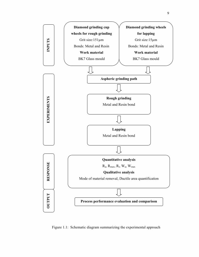
1.1 Schematic diagram summarizing the experimental
approach 9
2.1 Type of lenses a) Positive converging lens (convex)
b) Negative diverging lens (concave) (Anon, 2004) 13
2.2 Chromatic aberration and a plot of Focal length
vs. Wavelength 14
2.3 Longitudinal and Transverse spherical aberration 15
2.4 Off axis coma 16
2.5 Methods of reducing aberrations a) Adjusting
radius of curvature on both surfaces of the
lens b) Use of doublets made up of different
refractive index materials 17
2.6 Aspheric lens with one elliptical surface 18
2.7 Image formation by spherical mirror 18
2.8 Image formation by aspheric mirror 19
xiv
2.9 Diagram of various types of optical glass
produced by Schott 20
2.10 Electromagnetic spectrum of different
wavelengths of light 23
2.11 The working principle of thermographic camera 25
2.12 Some applications of thermography a) The middle
fuse clearly shows a loose connection which
through the ir camera is displayed as a hot spot
at 225 degrees F b) Infrared thermal profiling of an
automotive turbo charger c) Thermal image of
hot water filling a bathtub d) This aerial thermal
image was filmed from 3,000 feet. Note the white
warm underground hot water pipes that feed the
estate. Had there been a leak, it would be
immediately evident by a white plume 25
2.13 Grinding wheel structure 32
2.14 Schematic diagrams show (a) Ideal grain structure
with controlled grain spacing and projection height,
(b) Typical single-layer grinding wheel with random
grain spacing and projection height 32
2.15 Standard method of wheel marking order 34
2.16 Standard marking system for conventional bonded
abrasives wheel 34
2.17 Standard marking system for superabrasive
bonded wheel 35
xv
2.18 Aspheric lens generation procedure 36
2.19 Commonly used diamond grinding wheels in the
optical industry (a) Cup wheel for spheric, aspheric
and toric generation, (b and c) Cup wheel for toric
generation (d) Diamond cutting disks (e) Cup wheels
for surface milling (flats, prisms) (f) Electroplated
cup wheel for toric surfaces (g) Bevelling wheels
for profiling edges of the lens 37
2.20 Different types of pellets for lapping tool (a) Plain
pellet for flat surfces (b,c) Formed pellet for spheric,
aspheric surface generation (d) Pellet with centre hole 39
2.21 Different types of pellet holders (generating tools) for
(a) Edging or bevelling (b) Spheric concave lenses
(c) Spherical convex lenses (d) Grooving
(e) Flat optical windows 40
2.22 Line diagram shows (a) Basic scheme of surface
grinding operation similar to that of up milling
operation, (b) Cutting action of active grains that
are randomly distributed in the periphery of bonded
abrasive wheel 42
2.23 Three types of grain action in grinding (a) Micro-
cutting (b) Ploughing and (c) Rubbing 43
2.24 Parametric relations (a) Relationship between cutting
force and wheel depth of cut in the three phases of
grinding process (Lindberg, 1990), (b) Specific energy
decreases as metal removal rate is increased through
out the three stages in grinding operation 45
xvi
2.25 Schematic of surface grinding operation showing
individual undeformed chip and grinding parameters 45
2.26 Effect of indenter (a) Schematic illustration of point
indentation process showing developments of plastic
deformation, median cracks and lateral cracks leading
to chipping on hard and brittle materials (Lawn and
Wilshaw, 1975), (b) Different indenter geometry and
loading conditions provide different effect on ductile
and brittle materials 47
2.27 Model for elastic-plastic indention of brittle materials
showing dark region as hydrostatic core, shaded
region denotes plastic region and surrounding region
denotes elastic matrix 48
2.28 Effect of tool geometry (a) A sharp +ve rake
conventional cutting tool with the edge radius being
equal to depth of cut or even smaller, (b) A very
large -ve rake abrasive grain used in grinding,
(c) The 0o rake diamond tool working on an
ultraprecision machining at small depth of cut
behaves as a –ve rake tool, (d) Indentation sliding 49
2.29 Conventional machining processes versus
nanogrinding process 51
2.30 Scattergood’s model on ultraprecision machining
showing (a) 3-D view of diamond tool while
cutting material and (b) Cross sectional view of
the tool and workpiece 52
2.31 Critical stress field is a function of uncut chip
thickness; (a) Small depth of cut avoids the cleavage
xvii
to initiate at the defects and thus chip removal
process by plastic deformation, (b) Large depth
of cut results cleavage to initiate at the defects
and produce brittle fracture surface, (c) Schematic
diagram of cut surface 54
2.32 An original Konig’s model shows sharp and
flattened dull grain that cause brittle fracture due to
high infeeds and ductile cutting as a result from
frictional heat between lamellas 56
2.33 Konig’s model modified by Zhong and Venkatesh
(1995) shows uneven protrusions out of the bond
represent grain depth of cut. Abrasive grain on the
right side that protrudes slightly within critical
depth of cut region produces ductile streaks while on
the left side grain protrudes more than critical depth
of cut region produces fracture and deep crack 56
2.34 Surface roughness parameters 60
2.35 Surface roughness parameter Ra 61
2.36 Surface roughness parameter Rmax 61
2.37 Surface roughness parameter Rt 61
2.38 Surface waviness parameter Wa 62
2.39 Surface waviness parameter Wmax 62
3.1 Relative usages of the optical lenses with the
precision level 65
xviii
3.2 Aspheric generators a) Rank Taylor Hobson aspheric
generating machine illustrating chuck holding lens
to be generated and diamond tool holder b) Bell and
Howell aspheric generator, showing the work
spindle and the high speed diamond burr 68
3.3 Moore’s aspheric generator showing path trace for
convex and concave aspheric surfaces 69
3.4 Lens grinding by diamond grinding pin 70
3.5 Basic principle of grinding by zone 71
3.6 Grinding by zones generation method 72
3.7 Difference between a) Conventional method and
b) AEGM 73
3.8 Profile path trace in AEGM 73
3.9 Aspherical form control system and form control
flow structure 74
3.10 Bulged grinding tool mounted on robotic arm 75
3.11 Aspheric micro mould grinding (a) Grinding of
Micro aspheric insert (b) Close up view of micro
grinding wheel 76
3.12 A wide range of Toshiba models from 2 to 5 axes
ultraprecision turning and grinding machines 77
3.13 The principle of grinding 3D aspheric surface and
arrangement of the five axis control 79
xix
4.1 Glass blank geometry 82
4.2 Details of circular blank holding fixture (Section X-X) 84
4.3 Blank holding fixture showing glass blank fixed
with industrial wax 85
4.4 Schematic diagram of the rotary table equipped with
worm and worm wheel 86
4.5 Modified rotary table 87
4.6 Rotary motion transmission 89
4.7 PLC controller unit 89
4.8 Noritake’s diamond cup grinding wheel 90
4.9 Aspheric glass mould geometry 91
4.10 The sag difference between aspheric and its
corresponding profile 92
4.11 Tool path generation procedure 94
4.12 Different type of definitions required for generating
aspheric surface 95
4.13 Tool path verification process 96
4.14 Aspheric surface generation 97
4.15 Mitutoyo’s Formtracer CS5000 for quantitative
analysis of the glass moulds 100
xx
4.16 Surface imaging process 101
4.17 Detailed experimental plan 102
5.1 The sag difference between aspheric and its
corresponding profile 104
5.2 The influence of 5µm deviation from the nominal
value on percentage error through out the profile 106
5.3 Comparison of the parabolic parameter, P, during
Rough grinding and lapping operation using metal
and resin bonded wheel 107
5.4 GUI of Formpak 109
5.5 Comparison of various deviations between metal and
resin bonded wheel for rough milling operation 110
5.6 Different surface roughness parameters in rough
grinding and lapping operations with resin and
metal bonded wheel 113
5.7 Surface texture of the glass moulds ground with
a) Metal bonded b) Resin bonded grinding wheel of
grit size 151µm 114
5.8 Surface texture of the glass moulds lapped with
a) Metal bonded b) Resin bonded grinding wheel of
grit size 15µm 115
5.9 SEM image of the surface lapped with a) Metal
bonded wheel and b) Resin bonded wheel shows
more ductile streaks are evident on surface produced
xxi
with resin bonded wheel 115
5.10 SEM image of a) Rough ground and b) Lapped surface 116
5.11 Ductile area quantification with a) Metal bonded
wheel and b) Resin bonded wheel shows more
ductile streaks are evident on surface produced
with resin bonded wheel 117
5.12 Grinding wheel topography obtained from stylus
measurement method a) Resin bonded 15µm grain
size with magnified length of 250µm b) Resin
bonded 151µm grit size c) Metal bonded 15µm
grain size d) Metal bonded 151µm grit size 123
5.13 SEM image of metal bonded wheel for lapping
operation to estimate grain density (≈1100/mm2) 124
5.14 SEM image of metal bonded wheel for rough
grinding to estimate grain density (≈10/mm2) 124
5.15 SEM image of resin bonded wheel for lapping
operation to estimate grain density (≈1200/mm2) 124
5.16 SEM image of retal bonded wheel for rough
grinding to estimate grain density (≈12/mm2) 125
5.17 Conformity between grinding wheel and workpiece 127
5.18 Geometric model of grinding wheel conformity
with the glass mould 128
5.19 Circumferential section of grinding wheel coming
in contact with work giving contact a) Length and
xxii
b) Width 129
5.20 Different contact parameters in rough grinding
(left side) and lapping (right side) operation 131
5.21 Material removed by each grain in one revolution
of the grinding wheel 135
5.22 Form error of different aspheric generation techniques
In rough grinding and lapping operations 139
5.23 Roughness parameter Ra in different processes during
rough grinding and lapping operations 141
5.24 Roughness parameter Rmax of different techniques in
rough grinding and lapping operation 142
5.25 Roughness parameter Rt of different techniques in
rough grinding and lapping operation 143
5.26 Roughness parameter Wa of different process in
rough grinding and lapping operation 144
5.27 SEM images of the lapped surfaces with a) Metal
bonded wheel b) Resin bonded wheel c) Industrial
lapped sample 145
xxiii
LIST OF ABBREVIATIONS
AFM - Atomic force microscope
Al2O3 - Aluminium oxide or alumina
ANOVA - Analysis of variance
ap, ae, a - Wheel depth of cut or in-feed
b - Cutting width, wheel width of cut, width of platelet
CBN - Cubic boron nitride
CCD - Charge-couple-device, central composite design
CD - Compact disc
CNC - Computer numerical control
CVD - Chemical vapour deposition
dc - Critical depth of cut
DVD - Digital versatile or video disc
%E - % Error
E, E - Young’s modulus, mean percentage error
e…ei - Percentage error of martensite on the individual image
ELID - Electrolytic In-Process Dressing
f, f - feed
Fc, FH - Tangential cutting force
FEPA - Federation of European Producers of Abrasives
Ff - Feed cutting force
Fn, F - Normal cutting force
GIF - Graphic Interchange Format
H - Hardness of material
He-Ne - Helium-Neon
HK - Knoop hardness
xxiv
hmax - Grit depth of cut
IC - Integrated circuit
Kc, KIC - Fracture toughness
LCD - Liquid crystal display
LSI - Large scale integration
PV - Peak to valley
R - Tool nose radius
R1, R2 - Lens radius
Ra - Arithmetic mean roughness value
rc - Cutting ratio
Rmax - Maximum individual peak to valley height
Rt - Roughness parameter
SEM - Scanning electron microscope
SiC - Silicon carbide
SPDT - Single point diamond turning
t - Time
tc - Critical thickness of cut
u - Specific energy
Vc, Vs - Cutting speed
Vgw - Cutting speed of grinding wheel
Vft, Vwp - Table or work speed
Wa - Waviness height
Wmax - Waviness parameter
WC - Tungsten carbide
Wsm - Waviness spacing
x% - Percentage of carbon at eutectoid point
yc - Average depth of subsurface damage
yi - Percentage of ferrite or pearlite
Zeff - Damage transition line
xxv
Greek letters µm - Micrometer, micron
ρ - Density
α - Thermal expansion coefficient
φ - Shear angle
γ - Rake angle
κ - Approach cutting edge angle
µ - Coefficient of friction
λ - Wave length
θ - Angle of tilting
∆f - feed / grain
xxvi
LIST OF APPENDICES
APPENDIX TITLE PAGE
A List of publications 161
B Some of the general guide lines for using diamond
cup wheel for grinding operation 163
C Previous rotary table 164
D Parabolic parameter ‘P’ in rough grinding and lapping
operation with metal and resin bonded wheels 165
E Form accuracy in rough grinding and lapping operations 166
F Surface roughness parameters in grinding and lapping
operations 172
G SEM images of rough ground and lapped surface 173
H Ductile machined area quantification 174
I Process parameters comparison 182
J Surface roughness parameter with different aspheric
generation techniques 184
CHAPTER 1
RESEARCH OVERVIEW
1.1 Introduction
For an astonishingly large number of people in poor countries, uncorrected
vision prevents them from doing the things some of us take care for granted, like
reading street signs or comparing advertisements to decide which market has the best
price. According to World Health Organization, as many as billion peoples need
vision correction but will never get it. Eyeglasses are scarce in developing nations
because they cost too much for the average person, some time more costly than
average monthly income, causing just few peoples qualified to diagnose eye
problems and then provide the proper corrective lenses. In addition to this today, the
optical industry requires aspheric optics not only for the visible spectrum, but also
for high power and short wavelength radiation (eg X-rays, etc). At these
wavelengths, a great necessity exists for aspheric surfaces on brittle materials,
presenting the challenge of producing such complex optics as quickly as possible and
at the lowest possible cost. This research is mainly dedicated towards the efforts for
manufacturing the optical lenses with the use of general purpose vertical machining
centre to avoid the dependency on dedicated ultraprecision machining centres. The
present trend of the researchers and industrial practice was studied to identify the
requirements for flexible and less costly manufacturing of optical lenses. The lens
2
manufacturing could be the new horizon for small and medium scale industries if
they could manufacture optical lenses with their existing setup. The final outcome
of the research could be useful to convince such medium scale industries to step in
optical lens manufacturing.
1.2 Research Background
Options for machining brittle materials like glass or silicon have always
been scares. Cutting tools for the machining of glass are limited. Diamond is the
only cutting material which has been used effectively for machining glass. The use
of diamond for cutting glass can be found back in centuries as an example. For
instance, optical lenses are manufactured under different precision machining
levels and generally it can be sub divided into diamond turning and diamond
grinding.
However, advances in the precision machining of brittle materials have led to
the discovery of a "ductile regime" of operation in which material removal is by
plastic deformation. Fracture mechanics predicts that even in brittle solids, material
can be removed by the action of plastic flow, as is the case in metal, leaving crack
free surfaces when the removal process is performed at less than a critical depth of
cut (Puttick et al., 1989). It means that under certain controlled conditions, it is
possible to machine brittle materials like ceramics and glass using single or multi
point diamond tools so that material is removed by plastic flow, leaving a smooth
and crack-free surface. The diamond turning of germanium by Blackley and
Scattergood (1991), diamond turning of silicon by Yan et al (2002), and diamond
grinding of BK-7 glass by Bifano et al. (1991) using expensive ultra-precision
machine tools have demonstrated how ductile streaks can be generated on hard,
brittle materials when they are machined in a ductile mode. It has been reported that
almost 100% ductile mode machining is possible when machining hard materials
3
using a well defined geometry of single point single crystal diamond tools on a rigid
ultraprecision turning machine (Venkatesh et al., 1995). Instead of fully ductile
mode, partial ductile mode grinding is possible when grinding hard and brittle
materials on conventional Computer Numerical Control (CNC) machining centre
using diamond cup wheels. Previous studies indicated that getting partial ductile
streaks on the ground surface is a much better deal than a good surface finish as the
former from polishing experience shows that saturation has taken place with the
latter (Zhong and Venkatesh, 1995). Previous research work shows that in addition to
ductile mode grinding and conventional fracture mode grinding, the intermediate
mode of grinding, microcrack grinding, can also yield good results at a low cost.
Microcrack grinding can also be described as partial ductile grinding. The main idea
for using general purpose machine like Vertical Machining Centre (VMC) for
aspharising is to reduce the cost of the final product.
In the case of grinding, finishing post processes like polishing and lapping are
usually found to be more costly than other machining processes because of low their
per unit volume of material removal, and so its use tends to be looked upon as a
necessary evil. Partial ductile grinding is a more economical technology, where the
ground surface can be directly polished without the intervention of the lapping
process. The brittle materials can be ground in partial ductile mode on a CNC
machining center. Polishing time can also be reduced substantially as the amount of
ductile streaks can be increased in partial ductile grinding (Ong et al, 1994;
Venkatesh et al, 1995). With conventional grinding machines, less than 90% ductile
mode grinding is achievable and therefore the products require subsequent polishing
(Zhong and Venkatesh, 1995).
4
1.3 Problem Statement
Researchers and manufacturers have put in a lot of efforts achieving low
tolerances, better surface finish, and lower subsurface damage at reduced cost. In
order to reduce the total manufacturing time, it is preferable to obtain better
milled (rough ground) surfaces, even if it takes a little longer milling time, and
to reduce the polishing time and subsequently product cost. Various problems
reported by researchers and industry for producing aspheric lenses are as
follows:
a) Uneconomical ultraprecision machining
It has been reported that ultraprecision as well as conventional grinding has
been used to machine various profiles on hard and brittle materials. An
ultraprecise grinding machine, capable of producing nanometric relative
movements between the distributed cutting edges and work is required for
generating aspheric surfaces by grinding. Fully ductile mode grinding on these
materials is feasible when using high rigid ultraprecision machines, which
leads to no polishing but the process is found to be relatively too slow and too
costly for the products requiring less precision like ophthalmic lenses.
Conventional grinding has advantages over ultraprecision grinding with respect
to machining cost factor, able to machine at higher material removal rate but at
the marginal expense of form accuracy (Izman, 2004).
b) Need of low cost machining
Since grinding is the critical operation among the abrasive machining
processes (lapping and polishing) for removing material from hard, brittle
components, there is an obvious need to develop a low cost machining
5
technique that can minimize the subsurface damages of hard, brittle
materials during machining and at the same time generate abundant amount
of ductile streaks on the eventual machined workpieces.
c) Need of flexible machining and less setup time
The industrial procedures to manufacture aspheric lenses are employing very
simple but special purpose machines. These machines are mass production
machines capable of giving continuous output. The flexibility of the production
system is the main problem faced by the industry working with these machines.
These machines require very long setup time for small change in lens design.
Some time it is not at all possible for such machines to incorporate such design
changes in the lens geometry. In addition to this, the machine meant for
aspheric generation can not produce toroidal lenses if requirement arise.
d) Specialized manufacturing
The present trend of the general machine shops of mold manufacturers has
not been diverted towards glass moulds and lens manufacturing. The reason
behind this fact may be the highly classified technology for lens
manufacturing and lack of knowledge for machining the brittle materials like
glass on general industrial platform.
6
1.4 Objective of the Study
The objective of the research is as follows:
1. To propose a new method of generating aspheric surface on the glass mould
using conventional vertical machining centre.
2. To evaluate the performance of new method in terms of form accuracy and
surface finish.
3. To compare the new generation process with the industrial practice and zone
generation method in both, grinding and lapping operations.
1.5 Significance of the Study
The main emphasize in this project has been given on the general purpose
accessories which are easily available in the market at low cost. The lens making
industries are using highly specialized purpose machines like LOH aspheric
generators for making aspheric lenses. The grinding wheels used in these machines
are also specially designed for the typical geometry of the lens. Little variation in the
lens geometry takes considerable time to set these special purpose machines. In
addition to this, the machine meant for aspheric generation can not produce toroidal
lenses if requirement arise. Typical manufactured product that could be produced by
this method is the surface of the glass mould to manufacture plastic Fresnel lenses.
These lenses are having variety of applications; some require high degree of
accuracy such as lenses in the mobile camera whereas other could be liberal in
7
tolerance such as binocular lenses. The main idea of the research is to produce such
general purpose lens application by using the general purpose machine for
manufacturing.
1.6 Scope of the Study
The research was confined to the following limits:
1. The work material used was optical BK7 glass.
2. Grinding operation was carried out on a vertical machining centre.
3. Commercially available diamond cup grinding wheels with resin and metal
bond were used in the study for grinding and lapping operation. Grit sizes of
15µm and 151µm were used in the experiment for lapping and rough grinding
respectively.
4. Unigraphics NX2 was used to model the parabolic profile and to produce
aspheric grinding path for aspheric surface generation.
5. Scanning Electron Microscopy (S.E.M) and Optical Microscopy were used to
analyze the surface. Formtracer CH5000 along with Formpak profile analysis
software was used for surface roughness and form analysis. Image analysis
was done with KS300 and VideoTest V5 imaging software.
8
6. A special fixture was developed to hold the workpiece and to provide
additional rotation axis through modification of existing rotary table.
1.7 Overview of the Methodology
The overall methodology used for the experimentation to achieve the above
objectives is shown in Figure 1.1. The experiments planned involve the use of
151µm and 15µm grit size grinding wheels. The rough grinding and lapping
operations are planned sequentially to generate aspheric surface on the glass moulds.
The parameters for the grinding are planned in accordance with the industry and zone
generation method for evaluating the process performance. The results obtained are
compared with the industrial samples and zone generation method results. Detailed
qualitative and quantitative analysis was planned to examine surface texture of the
samples.
1.8 Organization of the Thesis
The new technique of aspheric surface generation is developed with use of
general vertical machining centre. The capability of vertical machining centre is
evaluated for optical lens manufacturing. This chapter begins with the background
of the problem that covers the issue leading to the problem statement. This is
followed by the problem statement, objective of the study, significance of the
study, scope of the study, overview of the methodology and ends with the
organization of this thesis. The second chapter gives broad view of the various
parameters of the optical grinding process, covering basic lens geometry with the
application of aspheric lenses, various material removal mechanisms in grinding,
9
Figure 1.1: Schematic diagram summarizing the experimental approach
Diamond grinding cup
wheels for rough grinding
Grit size:151µm
Bonds: Metal and Resin
Work material
BK7 Glass mould
Diamond grinding wheels
for lapping
Grit size:15µm
Bonds: Metal and Resin
Work material
BK7 Glass mould
Aspheric grinding path
Rough grinding
Metal and Resin bond
Lapping
Metal and Resin bond
Quantitative analysis
Ra, Rmax, Rt, Wa, Wmax
Qualitative analysis
Mode of material removal, Ductile area quantification
Process performance evaluation and comparison
INPU
TS
EX
PER
IME
NT
S R
ESP
ON
SE
OU
TPU
T
10
and type of grinding wheels used in optical industry. Third chapter narrowed to the
various aspheric surface generation processes. The aspheric generation processes
are divided in modification of conventional process and ultraprecision methods.
Fourth chapter is describing the pre-experimental work and methodology. Detail
plan of experiments is described in this chapter. Chapter five is the results of the
experiments. Thesis ends with conclusions drawn for this research.
REFERENCES
Andrew, C., Howes, T.D. and Pearce, T.R.A. (1985). Creep Feed Grinding. Industrial
Press. Inc. New York.
Anon. (1996). Schott Optical Glass Properties. Pocket Catalogue.
Anon. (2002). Tech Front: Defining Grinding Grains. Manufacturing Engineering. 6:24.
Anon. 2004 (online) available at http://www.wordiq.com/definition/Lens_(optics)
Aurich, J.C., Braun, O. and Wernecke, G. (2003). Development of a Superabrasive
Grinding Wheel with Defined Grain Structure using Kinematic Simulation.
Annals of the CIRP. 52(1): 275-280.
Bach, H. and Neuroth, N. (1995). The Properties of Optical Glass. Berlin Heidelberg:
Springer-Verlag.
Bejamin, R. J. (1979). Diamond Turning at a Large Optical Manufacturer. Optical
Engineering. 17(6): 574-577.
Berman, R. (1979). Thermal Properties, In: Field, J.E. (Ed.)., The Properties of
Diamond. London: Academic Press Inc. 1-22.
Bifano, T.G. and Fawcett, S.C. (1991). Specific Grinding Energy as an In-Process
Control Variable for Ductile-Regime Grinding. Precision Engineering. 13(4):
256-262.
Bifano, T.G., Dow, T.A. and Scattergood, R.O. (1991). Ductile-Regime Grinding: A
New Technology for Machining Brittle Materials. Trans. ASME. Journal of
Engineering for Industry.113: 184-189.
Bingham, R. G., Walker, D.D., Kim, D. H., Brooks, D., Freeman, R., and Riley, D.
(2000). A Novel Automated Process for Aspheric Surfaces. Proc. SPIE 4093:
445-450
Blackley, W.S. and Scattergood, R.O. (1991). Ductile-Regime Machining Model for
Diamond Turning of Brittle Materials. Precision Engineering. 13(2): 95-103.
Blake, P.N. and Scattergood, R.O. (1990). Ductile Regime Machining of Germanium
and Silicon. J. Am. Ceram. Soc. 73(4): 949-957.
154
Bowen, D.K. and Wormington, M. (1994). Measurement of Surface Roughnesses and
Topography at Nanometer Levels by Diffuse X-Ray Scattering. Annals of the
CIRP. 43(1):497-500.
Chapman, G. (2003). Enabling Technologies for Ultra-Precision Manufacturing &
Metrology. Technical talk presented on 18 January, 2003 at Faculty of
Mechanical Engineering, Universiti Teknologi Malaysia.
Chen,W. K., Kuriyagawa, T., Huang, H. and Yosihara, N. (2005). Machining Of Micro
Aspherical Mould Inserts Precision Engineering. 29(3): 315-323.
Clement, M.K.T. (1995). The Chemical Composition of Optical Glasses and its
Influence on the Optical Properties. In: Bach, H. and Neuroth, N. (Eds). The
Properties of Optical Glass. New York: Springer-Verlag.
Cook, N.H. (1966). Manufacturing Analysis. USA: Addison-Wesley Publishing Co. Inc..
Donaldson, R.D. (1979). Large Optics Diamond Turning Machine. Lawrence Livermore
National Laboratory Report UCRL-52812 (Vol.1).
Dunnington, B.W. (1978). Diamonds for Abrasive Machining, Lapping, Polishing and
Finishing. SME Technical Paper. MR78- 955:1-8.
Evans, C. (1989) Precision Engineering: An Evolutionary View. Cranfield Press,
Bedford England.
Fang, F.Z. and Chen, L.J. (2000). Ultra-Precision Cutting of ZKN7 Glass. Annals of the
CIRP.49(1): 17-20.
Fang, F.Z. and Venkatesh, V.C. (1998). Diamond Cutting of Silicon with Nanometric
Finish. Annals of the CIRP. 47(1): 45-49.
Fang, F.Z., Venkatesh, V.C. and Zhang, G.X. (2002). Diamond Turning of Soft
Semiconductors to Obtain Nanometric Mirror Surfaces. International Journal of
Advanced Manufacturing Technology. 19: 637-641.
Fiedler, K.H. (1995). Processing (Grinding and Polishing). In: Bach, H. and Neuroth, N.
(Eds). The Properties of Optical Glass. New York: Springer-Verlag
Groover, M.P. (1996). Fundamentals of Modern Manufacturing: Materials, Processes
and Systems. USA: Prentice-Hall International, Inc..
Hensz, R.R. (1969). Glass Grinding and Polishing. SME Technical paper. MR69-230: 1-
11.
155
Herbert, S. (1972). A Marriage of Success. Industrial Diamond Review: 375-378,
September 1972.
HMT. (1980). Production Technology. New Delhi: Tata McGraw Hill Publishing
Company Limited.
Holz, R. and Sauren, J. (1988). Grinding with Diamond and CBN. WINTER Diamond
and CBN Tools Catalogue. Ernst Winter & Sohn Diamantwerkzeuge GmbH &
Co.
Horne, D.F. (1983). Optical Production Technology. 2nd Edition. Bristol: Adam Hilger
Ltd.
Hung, N.P. and Y.Q. Fu. (2000). Effect of Crystalline Orientation in the Ductile-Regime
Machining of Silicon. International Journal of Advanced Manufacturing
Technology. 16: 871-876.
Inasaki, I. (1987). Grinding of Hard and Brittle Materials. Annals of the CIRP. 36(2):
463-471.
Inasaki, I., Tonshoff, H.K. and Howes, T.D. (1993). Abrasive Machining in the Future.
Annals of the CIRP. 42(2): 723-732.
Izman, S. (2004). Investigation into some aspects of partial ductile mode in wet and dry
grinding of optical glass, Universiti Teknologi Malaysia: PhD Thesis.
Izman, S., Venkatesh, V.C., Sharif, S., Mon, T.T. and Konneh, M. (2003). Assessment
of Partial Ductile Mode Grinding of Optical Glass. Dojyo Workshop on. High
Speed Machining of Hard/Super Hard Materials. Copthorne Orchid Hotel,
Singapore: 121-126.
Izumitani, T., (1979). Polishing, Lapping and Diamond Grinding of Optical Glasses.
Treatise on Material Science and Technology. Academic Press Inc., New York,
17: 116-149.
Kalpakjian, S. (1995). Manufacturing Engineering and Technology. 3rd Edition, New
York: Addision-Wesley Publishing Company.
Kapoor, A. (1993). A Study on Mechanism of Aspheric Grinding of Silicon. Tennessee
Technological University, USA: M.Sc. Thesis.
Kibbe, R.R., Neely, J.E., Meyer, R.O. and White, W.T. (1987). Machine Tool Practices.
3rd Edition. Singapore: John Wiley & Sons.
156
Kitajima, K., Cai, G.Q., Kumagai, N. and Tanaka, Y. (1992). Study on Mechanism of
Ceramics Grinding. Annals of the CIRP. 41(1): 367-371.
Komanduri, R. Lucca, D.A. and Tani, Y. (1997). Technological Advances in Fine
Abrasive Processes. Keynote Paper. Annals of the CIRP. 46(2): 545-596.
Konig, W. and Sinhoff, V. (1992). Ductile Grinding of Ultraprecise Aspherical Optical
Lenses. International Symposium of Optical Systems Design. Berlin.
Konneh, M. (2003). An Experimental Investigation on Partial-Ductile Mode Grinding of
Silicon. Universiti Teknologi Malaysia: Ph.D Thesis.
Koshy, P., Zhou, Y., Guo, C. and Chand, R. (2005). Novel kinematics for cylindrical
grinding of brittle materials. Annals of CIRP 2005.
Kuriyagawa, T., Zahmaty M. and Syoji, K. (1996). A new grinding method for aspheric
ceramic mirrors. Journal of Materials Processing Technology. 62: 387-392
Lawn, B.R. and Wilshaw, R. (1975). Indentation Fracture: Principles and Applications.
Journal of Material Science. 10: 1049-1081.
Lawn, B.R., and Evans, A.G. (1977). A Model for Crack Initiation in Elastic/Plastic
Indentation Fields. Journal of Material Science. 12: 2195-2199.
Lawn, B.R., Evans, A.G. and Marshall, D.B. (1980). Elastic-Plastic Indentation Damage
in Ceramics: The Median/Radial Crack System. Journal of American Ceramics
Society. 63: 574-581.
Lewis, T. G. (1962). Machining to millionths. The Tool and Manufacturing Engineer,
49(2)65-68.
Lim, H.S., Fathima, K., Kumar, A.S. and Rahman, M. (2002). A Fundamental Study on
the Mechanism of Electrolytic In-Process Dressing (ELID) Grinding.
International Journal of Machine Tools & Manufacture. 42: 935-943.
Lindberg, R.A. (1970). Processes and Materials of Manufacture. New Delhi: Prentice
Hall of India Pte. Ltd.
Lindberg, R.A. (1990). Processes and Materials of Manufacture. 4th Edition. New
Jersey: Prentice Hall, Inc..
Lubarsky S.V., Sobolev V.G., Shevtsov S.E. (1990). Optical Surface Fabrication on
Ultra Precision Machine. Proc. SPIE 1266:226-236.
157
Maldague, X. (2001). Theory and practice of Infrared Technology for Nondestructive
Testing, John Wiley & Sons Inc, N.Y.
Malkin, S. (1989). Grinding technology : Theory and Application of Machining with
Abrasives. England: Ellis Horwood Limited.
Marker, A.J. and Neuroth, N. (1995). Overview- Optical Glass: An Engineered Material.
In: . Bach, H. and Neuroth, N. (Eds). The Properties of Optical Glass. New York:
Springer-Verlag.
Mayer, J.E. and Fang, G.P. (1994). Effect of Grit Depth of Cut on Strength of Ground
Ceramics. Annals of the CIRP. 43(1): 309-312.
McKeown, P.A., Carlisle, K., Shore, P. and Read, R.F.J. (1990). Ultraprecision, High
Stiffness, CNC Grinding Machines for Ductile Mode Grinding of Brittle
Materials, Infrared Technology and Applications. SPIE .1320: 301-313.
Meyer Arendt, J. R.. (1972). Introduction to Classical and Modern Optics. Prentice Hall,
Inc. 103-104
Miyashita, M. (1989). Brittle/Ductile Machining. Fifth International Seminar on
Precision Engineering. Monterey, CA. USA.
Nakasuji, T., Kodera, S., Matsunaga, H., Ikawa, N. and Shimada, S. (1990). Diamond
Turning of Brittle Materials for Optical Components. Annals of the CIRP. 39(1):
89- 92.
Namba, Y. and Abe, M. (1993). Ultraprecision Grinding of Optical Glasses to Produce
Super-Smooth Surfaces. Annals of the CIRP. 42(1): 417-420.
Namba, T., Kobayashi, H., Suzuki, H. and Yamashita, K. (1999). Ultraprecision Surface
Grinding of Chemical Vapor Deposited Silicon Carbide for X-Ray Mirrors using
Resinoid-Bonded Diamond Wheels. Annals of the CIRP. 48(1): 277-280.
Namba, Y., Wada, R., Unno, K. and Tsuboi, A. (1989). Ultra-precision Surface Grinder
Having a Glass-Ceramic Spindle of Zero-Thermal Expansion. Annals of the
CIRP.38(1):331-334.
Namba, Y., Yamada, Y., Tsuboi, A., Unno, K., Nakao, H. (1992). Surface Structure of
Mn-Zn Ferrite Single Crystals Ground by an Ultraprecision Surface Grinder with
Various Diamond Wheels. Annals of the CIRP. 41(1): 347-351.
158
Nicholas D. J and Boon, J. E. (1981). The Generation Of High Precision Aspherical
Surfaces In Glass By CNC Machining J. Phys. D: Appl Phys. 14: 593-600
Ohmori, H., Kato, J., and Masaru, H. K. (1996) Ultraprecision Form Control of Aspheric
Mirror with ELID Grinding. Spring-8 Annul Report: 218-219
Ong, N.S. and Venkatesh, V.C. (1988). Semi-Ductile Grinding and Polishing of Pyrex
Glass. Journal of Material Processing Technology. 83: 261-266.
Pai, D.M., Ratterman, E. and Shaw, M.C. (1989). Grinding Swarf. Wear. 131: 329-339.
Pearce, C.A. (1972). Silicon Chemistry and Applications. London: The Chemical
Society.
Puttick, K. E., Rudman, M.R., Smith, K.J., Franks, A. and Lindsay, K. (1989). Single-
point Diamond Machining of Glasses. Proc. R. Soc. Lond. A426: 19-30.
Puttick, K.E. and Hosseini, M.M. (1980). Fracture by a Pointed Indenter on Near (111)
Silicon. J. Phys. D. App. Phys. 13: 875-880.
Rao, P.N. (2000).Manufacturing Technology: Metal Cutting & Machine Tools. Tata
New Delhi: McGraw-Hill Publishing Company Limited.
Reichenbach, G.S., Mayer, Jr. J.E., Kalpakcioglu, S. and Shaw, M.C. (1956). The Role
of Chip Thickness in Grinding. Trans. ASME. 18: 847-850.
Rusell R G (1993) Comparison Of Metal And Resinoid Bonded Grinding Wheels With
Various Grit Sizes In The Aspheric Surface Generation Of Silicon Lenses.
Tennessee Technological University, USA: M.Sc. Thesis.
Schinker, M.G. (1991). Subsurface Damage Mechanisms at High-Speed Ductile
Machining of Optical Glasses. Precision Engineering. 13(3): 208-218.
Shafrir (2004). Diamond Tool Wear - Observation by Scanning Electron Microscopy
(SEM). Practical Scanning Electron Microscopy and Advanced Topics. Opt
307/507
Shaw, M.C. (1969). Metal Cutting Principles. 3rd Edition. New Delhi: Oxford & IBH
Publishing Co.
Shaw, M.C. (1972). A New Theory of Grinding. Mech. and Chem. Eng. Trans.
Institution of Engrs. (Australia). MC8: 73-78.
Stephenson, D. A. and Agapiou, J.S. (1997). Metal Cutting Theory and Practice. New
York : Marcel Dekker, Inc.
159
Subramaniam and Ramanath. (1991). Principles of Abrasive Machining. Ceramics and
Glasses. Engineered Materials Handbook vol.4, ASM International, The
Materials Information Society:316.
Suzuki, H., and Murakami, S. (1995) An ultraprecision grinding machine for non-
axisymmetric aspheric mirrors Nanotechnology (6):152-157.
Tabor, D. (1970). The hardness of Solids. Proc. of the Institute of Physics, F. Physics in
Technology. 1: 145-179.
Tabor, D. (1986). Indentation Hardness and Its Measurement: Some Cautionary
Comments, in Micro-Indentation Techniques in Material Science and
Engineering. ASTM STP 889. Eds. P.J. Blau and B.R. Lawn: 129-159.
Tan, C.P. (1990). Aspheric Surface Grinding and Polishing of Thermal Imaging
Materials. Tennessee Technological University, Cookville, USA: M.Sc. Thesis.
Tonshoff, H.K, Egger, R., Longerich, W. and Preising, D. (1998). Superfinishing
Ceramics. Manufacturing Engineering: 52-60.
Ukam (2004) Industrial Superhard Tools Catalogue, 2004
Van Ligten, R.F. and Venkatesh, V.C. (1985). Diamond Grinding of Aspheric Surfaces
n CNC 4-Axis Machining Centre. Annals of the CIRP. 34(1): 295-298.
Venkatesh, V. C. and Zhong, Z. (1995). Semi-ductile Grinding and Polishing of
Ophthalmic Asperics and Spherics. Annals of CIRP. 44(1): 339 - 342.
Venkatesh, V.C., Chandrasekaran, H. (1987). Experimental Techniques in Metal
Cutting. New Delhi: Prentice-Hall of India Pte. Ltd.
Venkatesh, V.C., Fang, F. and Chee, W.K. (1997). On-Mirror Surfaces Obtained with
and without Polishing. Annals of the CIRP.46(1): 505-508.
Venkatesh, V.C., Inasaki, I., Toenshof, H.K., Nakagawa, T. and Marinescu, I.D. (1995).
Observations on Polishing and Ultra-Precision Machining of Semiconductor
Substrate Materials. Keynote Paper. Annals of the CIRP. 44(2): 611-618.
Volker, S., (1992). Ductile Grinding Of Ultraprecise Aspherical Optical Lenses.
International Symposium Of Optical System Design. Berlin, Germany.
Walker, D.D, Brooks, D., Freeman, R., King, A., McCavana, G., Morton, R., Riley, D.
and Simms, J. (2001) First Aspheric Form and Texture Results From a
160
Production Machine Embodying the Precession Process. Proc. SPIE Vol. 4451:
267-276, Optical Manufacturing and Testing IV; H. Philip Stahl; Ed., Dec 2001.
Walker, D.D., Beaucamp, A.T.H., Bingham, R. G., Brooks, D., Freeman, R., Kim, S.W.,
King, A., McCavana, G., Morton, R., Riley, D. and Simms, J. (2002). The
Precessions Process for Efficient Production of Aspheric Optics for Large
Telescopes and Their Instrumentation. Proc. SPIE Astronomical Telescopes and
Instrumentation Meeting, Hawaii. 4842: 73-84.
Walker, D.D., Beaucamp, A.T.H., Bingham, R. G., Brooks, D., Freeman, R., Kim, S.W.,
King, A., McCavana, G., Morton, R., Riley, D. and Simms, J. (2003).
Precessions Aspheric Polishing:- New Results from the Development Program.
Proc. SPIE 5180: 15-28, Optical Manufacturing and Testing V. H. Philip Stahl.
Ed. Dec 2003.
Walker, D.D., Brooks, D., Freeman, R., King, A., McCavana, G., Morton, Kim, S.W.
(2003). The ‘Precessions’ Tooling for Polishing and Figuring Flat, Spherical and
Aspheric Surfaces. 11(8). OPTICS EXPRESS 958.
Walker, D.D., Freeman, R., McCavana, G., Morton, R., Riley, D., Simms, J., Brooks, D.,
and King, A. (2001). The Zeeko/UCL Process for Polishing Large Lenses And
Prisms. proc. Large Lenses and Mirrors conference, UCL, March 2001, pub.
SPIE: 106-111.
Winter, (1996). Diamond Tools for Machining Precision Optical Glass, Spectacle
Lenses and Technical Glass Components. Ernst Winter & SOHN
Diamantwerkzeuge GmbH & Co.
Xiangdong, L. (2000) Ultraprecision Turning Technology. SIMTech technical report.
(PT/00/008/PM).
Xu, X., Yu, Y. and Huang, H. (2003). Mechanisms of Abrasive Wear in the Grinding of
Titanium (TC4) and Nickel (K417) Alloys. Wear. 255: 1421–1426.
Yan, J, Syoji, K., Kuriyagawaa, T. and Suzuki, H. (2002a). Ductile Regime Turning At
Large Tool Feed. Journal of Materials Processing Technology. 121: 363–372.
Zhong, Z. and Venkatesh, V.C. (1995). Semi-Ductile Grinding and Polishing of
Ophthalmic Aspherics and Spherics. Annals of the CIRP. 44(1): 339-342.
161
List of Publications and Awards
[1] Venkatesh, V.C., Izman, S., Vichare, P.S., Mon, T.T., Murugan, S.,(2005) The
Novel Bondless Wheel, Spherical Glass Chips And A New Method of Aspheric
Generation, Int. J. of Mat. Proc. Tech. Vol. 167 :184-190.
[2] Venkatesh, V.C., Izman, S., Vichare, P.S., (2005) Development of a novel
bondless diamond grinding wheel for machining IC chips for failure analysis and
for generation of aspheric surface, 55th CIRP General Assembly, Aug 2005,
Antalya, Turkey.
[3] P.S. Vichare, S. Izman, V.C. Venkatesh, C. Woo, S. Murugan. (2005) Novel and
flexible method of generating aspheric glass moulds, Manufacturing Systems
Development - Industry Expectations. Machine Engineering, Vol. 5(3-4):45-59.
[4] V.C. Venkatesh, S. Izman, P.S. Vichare, C. Woo, S. Murugan (2005) New method
of aspheric generation for manufacturing glass moulds on machining centres,
International Journal for Manufacturing Science & Technology. Vol 8 (2). 29-34.
[5] Venkatesh V.C., Izman S., Mon T.T., Vichare P.S (2005) Critical depth of cut in
vertical diamond grinding 24th All India Manufacturing Technology, Design and
Research Conference (AIMTDR), Bangalore, India. pp. 128-133.
[6] Vichare P.S., Venkatesh V.C., Izman S., Rahim E. A., Hassan O., (2006) Flexible
Process for Generating Aspheric Surface on the Glass moulds, ICMM2006, Kuala
Lumpur, Malaysia.
[7] Venkatesh, V.C., Vichare, P.S., Izman, S., (2006) Kinematics Of Material
Removal Process in Aspheric Surface Generation On Glass Moulds,
ICOMAST2006, Melaka, Malaysia.
APPENDIX A