IOSR Journal of Engineering (IOSRJEN) ISSN: 2250-3021 Volume 2, Issue 7(July 2012), PP 82-90 www.iosrjen.org www.iosrjen.org 82 | P a g e Performance Evaluation of Multi Carrier Based PWM Techniques for Single Phase Five Level H-Bridge Type FCMLI E.Sambath 1 , S.P. Natarajan 2 , C.R.Balamurugan 3 1 Department of EIE, Annamalai University, Chidambaram, Tamilnadu, India 2 Department of EIE, Annamalai University, Chidambaram, Tamilnadu, India 3 Department of EEE, Arunai Engineering College, Thiruvannamalai, Tamilnadu, India ABSTRACT : - The Flying Capacitor Multi Level Inverter (FCMLI) has a great advantage with respect to the availability of voltage redundancies. This work proposes a switching pattern for a modified inverter structure. It is used to improve the performance of chosen single phase five level H-bridge type FCMLI as compared to conventional FCMLI. The chosen multi level inverter is simulated for various multicarrier based Pulse Width Modulation(PWM) techniques for a resistive load. The PWM techniques include Phase Disposition (PD) PWM, Phase Opposition and Disposition (POD) PWM, Alternative Opposition and Disposition (APOD) PWM, Carrier Overlapping (CO) PWM, Phase Shift (PS) PWM and Variable Frequency (VF) PWM and the harmonics of the output voltages are observed for various modulation indices. The performance of chosen FCMLI is confirmed through MATLAB-SIMULINK based simulation. It is observed that sinusoidal reference with PODPWM provides output with relatively low distortion. Its also seen that COPWM strategy is found to perform better since it provides relatively higher fundamental RMS output voltage. Keywords: – CF, DF, FCMLI, FF, PSPWM, THD, VF I. INTRODUCTION Power switches with the suitable switching frequency at ratings above 5kV are rare; hence it is difficult to achieve inverter output voltage which is compatible to the medium voltage grid. One approach is to utilize the MLI structure. Multilevel inverter is an array of power semiconductor switches and voltage sources which is switched in a manner that an output voltage of stepped waveform is generated. Several multilevel topologies have evolved: most common are the Diode Clamped Multilevel Inverter (DCMLI), flying-capacitor multilevel inverter and Modular Structured Multilevel Inverter (MSMI). In addition there are emerging multilevel topologies such as the asymmetric hybrid multi level inverters and soft-switching multilevel inverters. Jeon et al [1] introduced a symmetric carrier technique of CRPWM for voltage balance method of flying capacitor multilevel inverter. Boora et al [2] proposed voltage sharing converter to supply single phase asymmetrical four level diode clamped inverter with high power factor loads. Panagis et al [3] have discussed comparison of state of the art multilevel inverters. Tolbert et al [4] have proposed elimination of harmonics in a multilevel converter with nonequal DC sources. Nami et al [5] have presented a hybrid cascade converter topology with series connected symmetrical and asymmetrical diode clamped H-bridge cells. Shanthi and Natarajan [6] have carried out comparative study on carrier overlapping PWM strategies for five level flying capacitor inverter. Porselvi and Muthu [7] have also compared cascaded H-bridge, neutral point clamped and flying capacitor multilevel inverters using multicarrier PWM. Haiwen et al [8] have discussed hybrid cascaded multilevel inverter with PWM control method. Ramani [9] presented switching pattern selection scheme based 11 level flying capacitor multilevel inverter fed induction motor. Shukla et al [10] analyzed flying capacitor multilevel inverter and its applications in series compensation of transmission lines. This literature survey reveals few papers only on various PWM techniques and FCMLI. Hence this work presents a new approach for controlling the harmonics of output voltage of chosen H-bridge type FCMLI fed resistive load employing sinusoidal reference. Simulations are performed using MATLAB-SIMULINK. II. MULTILEVEL INVERTER MLIs divide the main DC supply voltage into several DC sources which are used to synthesize an AC voltage from a stepped approximation of the desired sinusoidal waveform. The stepped approximation is also popularly known as the staircase model. The number of stages (cells or capacitors depending on the respective topology) helps decide the power capacity of the converter as a whole. Suitable connections either in series or shunt mode or both are done to achieve higher voltage and/or current ratings. One of the biggest advantages of using a MLI is that the transformer can be eliminated and this helps enhance efficiency and cost effectiveness. Additional features such as its battery management capability, redundant switching states in inverter operation, and scalability make the cascade inverter the MLI of choice.
Techniques for Single Phase Five Level H-Bridge Type FCMLI
E.Sambath1, S.P. Natarajan
2, C.R.Balamurugan
3
1Department of EIE, Annamalai University, Chidambaram, Tamilnadu, India 2Department of EIE, Annamalai University, Chidambaram, Tamilnadu, India
3Department of EEE, Arunai Engineering College, Thiruvannamalai, Tamilnadu, India
ABSTRACT : - The Flying Capacitor Multi Level Inverter (FCMLI) has a great advantage with respect to the availability of voltage redundancies. This work proposes a switching pattern for a modified inverter structure. It
is used to improve the performance of chosen single phase five level H-bridge type FCMLI as compared to
conventional FCMLI. The chosen multi level inverter is simulated for various multicarrier based Pulse Width
Modulation(PWM) techniques for a resistive load. The PWM techniques include Phase Disposition (PD) PWM, Phase Opposition and Disposition (POD) PWM, Alternative Opposition and Disposition (APOD) PWM, Carrier
Overlapping (CO) PWM, Phase Shift (PS) PWM and Variable Frequency (VF) PWM and the harmonics of the
output voltages are observed for various modulation indices. The performance of chosen FCMLI is confirmed
through MATLAB-SIMULINK based simulation. It is observed that sinusoidal reference with PODPWM
provides output with relatively low distortion. Its also seen that COPWM strategy is found to perform better
since it provides relatively higher fundamental RMS output voltage.
Keywords: – CF, DF, FCMLI, FF, PSPWM, THD, VF
I. INTRODUCTION
Power switches with the suitable switching frequency at ratings above 5kV are rare; hence it is difficult
to achieve inverter output voltage which is compatible to the medium voltage grid. One approach is to utilize the
MLI structure. Multilevel inverter is an array of power semiconductor switches and voltage sources which is
switched in a manner that an output voltage of stepped waveform is generated. Several multilevel topologies have evolved: most common are the Diode Clamped Multilevel Inverter (DCMLI), flying-capacitor multilevel
inverter and Modular Structured Multilevel Inverter (MSMI). In addition there are emerging multilevel
topologies such as the asymmetric hybrid multi level inverters and soft-switching multilevel inverters. Jeon et al
[1] introduced a symmetric carrier technique of CRPWM for voltage balance method of flying capacitor
multilevel inverter. Boora et al [2] proposed voltage sharing converter to supply single phase asymmetrical four
level diode clamped inverter with high power factor loads. Panagis et al [3] have discussed comparison of state
of the art multilevel inverters. Tolbert et al [4] have proposed elimination of harmonics in a multilevel converter
with nonequal DC sources. Nami et al [5] have presented a hybrid cascade converter topology with series
connected symmetrical and asymmetrical diode clamped H-bridge cells. Shanthi and Natarajan [6] have carried
out comparative study on carrier overlapping PWM strategies for five level flying capacitor inverter. Porselvi
and Muthu [7] have also compared cascaded H-bridge, neutral point clamped and flying capacitor multilevel inverters using multicarrier PWM. Haiwen et al [8] have discussed hybrid cascaded multilevel inverter with
PWM control method. Ramani [9] presented switching pattern selection scheme based 11 level flying capacitor
multilevel inverter fed induction motor. Shukla et al [10] analyzed flying capacitor multilevel inverter and its
applications in series compensation of transmission lines. This literature survey reveals few papers only on
various PWM techniques and FCMLI. Hence this work presents a new approach for controlling the harmonics
of output voltage of chosen H-bridge type FCMLI fed resistive load employing sinusoidal reference.
Simulations are performed using MATLAB-SIMULINK.
II. MULTILEVEL INVERTER MLIs divide the main DC supply voltage into several DC sources which are used to synthesize an AC
voltage from a stepped approximation of the desired sinusoidal waveform. The stepped approximation is also
popularly known as the staircase model. The number of stages (cells or capacitors depending on the respective
topology) helps decide the power capacity of the converter as a whole. Suitable connections either in series or
shunt mode or both are done to achieve higher voltage and/or current ratings. One of the biggest advantages of
using a MLI is that the transformer can be eliminated and this helps enhance efficiency and cost effectiveness.
Additional features such as its battery management capability, redundant switching states in inverter operation,
and scalability make the cascade inverter the MLI of choice.
Performance Evaluation of Multi Carrier Based PWM Techniques for Single Phase Five Level
H- Bridge Type FCMLI
www.iosrjen.org 83 | P a g e
II. (a) Conventional FCMLI
FCMLI is similar to the Neutral Point Clamped (NPC) topology. Also known as the capacitor-clamped MLI topology it allows more flexibility in waveform synthesis and helps balance voltage across the clamped
capacitors. A conventional single phase five level FCMLI topology is shown in Fig.1. One of the biggest
advantages of FCMLI over the NPC topology is that one capacitor replaces two diodes (clamping / anti-parallel
diodes) resulting in a natural simplification of topology and reduction in overall losses.
Fig. 1 Conventional single phase five level FCMLI
m-level flying capacitor multilevel inverter has ‘m’ levels of output voltage. All the capacitors are of
equal value; an m-level inverter will require a total of (m-1)×(m-2)/2 clamping capacitors per phase leg in
addition to (m-1) main dc bus capacitors. The DC bus consists of four capacitors acting as voltage divider. For a
DC bus voltage Vdc, the voltage across each capacitor is Vdc/4 and voltage stress on each device is limited to Vdc/4 through clamping capacitor. If the voltage of the main DC-link capacitor is Vdc, the voltage of the
innermost capacitor clamping the innermost two devices is Vdc/(m-1). The middle point of the four capacitors
‘n’ can be defined as the neutral point. The numbering order of switches is S1, S2, S3, S4, S1’, S2’, S3’ and S4’.
The switches are grouped into four pairs (S1,S1’), (S2,S2’), (S3,S3’) and (S4,S4’). Thus if S1 is ON, S1’ is
OFF and vice-versa. The output voltage Van has five states: Vdc/2, Vdc/4, 0, - Vdc/4 and - Vdc/2.
II. (b) Chosen H-bridge type FCMLI
All the clamping capacitors in FCMLI are equal values. The size of the voltage increases between two
consecutive legs of the clamping capacitors and hence the size of voltage steps in the output waveform and the
elimination of the lower order harmonics. In this paper, a five level symmetrical flying capacitor multilevel
inverter uses a modified switching technique in such a way that the number of clamping capacitors is minimized
and hence an expected decrease in the converter’s switching losses. This topology promises low harmonic
distortion and hence there would be no need of filters to provide switch combination redundancy for balancing different voltage levels, Table 1 shows that comparisons of power components used in conventional as well as
chosen FCMLI. Fig.2 shows a configuration of single phase five level H-bridge type FCMLI. Here also the
same output voltage states exist: Vdc/2, Vdc/4, 0, - Vdc/4 and - Vdc/2. To study the operation of the chosen H-
bridge type FCMLI, the PWM scheme has been simulated using MATLAB – SIMULINK / POWER SYSTEM
BLOCKSET / POWER GUI. The gating pulses for the inverter are generated for various values of modulation
index ma and for various PWM techniques. The simulation results for the different modulation indices with
multicarrier SPWM of chosen FCMLI is presented for ma ranging from 0.6-1.
Fig. 2 Chosen single phase H-bridge type five level FCMLI
Performance Evaluation of Multi Carrier Based PWM Techniques for Single Phase Five Level
H- Bridge Type FCMLI
www.iosrjen.org 84 | P a g e
Table-1 Comparison between conventional and chosen FCMLIs
III. INVERTER TOPOLOGY AND SWITCHING STATES Several modulation strategies have been developed for multilevel inverters. The most common used is
the multi carrier sub harmonic PWM technique. The principle of the multicarrier PWM is based on a
comparison of a sinusoidal reference waveform with triangular carrier waveforms. m-1 carriers are required to generate m levels. The carriers are in continuous bands around the reference zero. They have the same
amplitude Ac and the same frequency fc. The sine reference waveform has a frequency fr and Ar is the peak to
peak value of the reference waveform. At each instant, the result of the comparison is 1 if the triangular carrier
is greater than the reference signal and 0 otherwise. The output of the modulator is the sum of the different
comparisons which represents the voltage level. The strategy is therefore characterized by the two following
parameters called amplitude modulation index ma and frequency modulation index mf:
mf = 𝑓𝑐
𝑓𝑟
The amplitude modulation indices are for
(i) PDPWM, PODPWM, APODPWM and VFPWM: 2𝐴𝑟
𝑚−1 ∗𝐴𝑐
(ii) COPWM = 𝐴𝑟
(𝑚
4)∗ 𝐴𝑐
(iii) PSPWM = 𝐴𝑟
(𝐴𝑐2
)
This paper uses all well known multicarrier based multilevel PWM strategies such as PDPWM,
PODPWM, APODPWM, COPWM, PSPWM and VFPWM. Fig.3 shows the sample SIMULINK model
developed for PSPWM technique for chosen inverter and Fig.4 shows the sample source block.
Fig. 3 Sample SIMULINK model developed for chosen single phase inverter for PSPWM technique
Fig. 4 Sample source block in SIMULINK for triangular carrier.
Type of MLI
Conventional
FCMLI
Chosen
FCMLI
Main power devices 8 8
Main diodes 8 8
Clamping capacitor 6 2
DC bus capacitors 4 2
No. of leg 1 2
Performance Evaluation of Multi Carrier Based PWM Techniques for Single Phase Five Level
H- Bridge Type FCMLI
www.iosrjen.org 85 | P a g e
IV. TYPES OF CARRIER BASED SPWM TECHNIQUES
Sinusoidal PWM can be classified according to carrier and modulating signals. This work used the
intersection of a sine wave with a triangular wave to generate firing pulses. There are many alternative strategies
to implement this. They are as given below.
Phase Opposition Disposition (POD) PWM where the carriers above the zero reference are in phase but
shifted by 180° from those carriers below the zero reference.
Alternative Phase Opposition Disposition (APOD) PWM where each carrier band is shifted by 180° from the adjacent bands.
In Phase Disposition (PD) PWM all the carriers are in phase.
Phase Shift PWM (PSPWM) : all carrier signals have the same amplitude and frequency but they are phase
shifted by 90 degrees to each other.
Carrier Overlapping PWM (COPWM): all carriers with the same frequency and same peak to peak amplitude
are disposed such that the bands they occupy overlap each other.
Variable Frequency PWM (VFPWM): carriers have the variable frequency and same amplitude each other.
IV. (a) Phase Opposition Disposition (POD) PWM
The rules for phase opposition disposition method for a multilevel inverter are
1) 4 carrier waveforms are arranged as in Fig.5 in phase opposition disposition.
2) The converter is switched to + Vdc/2 when the sine wave is greater than both upper carriers. 3) The converter is switched to + Vdc/4 when the sine wave is greater than first upper carrier.
4) The converter is switched to zero when sine wave is lower than upper carrier but higher than the lower
carrier.
5) The converter is switched to – Vdc/4 when the sine wave is less than first lower carrier.
6) The converter is switched to - Vdc/2 when the sine wave is less than both lower carriers.
The above same rule is applicable to all PWM strategy i.e. PD,POD,APOD,CO,PS,VF
Fig. 5 Carrier arrangement for PODPWM strategy (ma=0.8 and mf=22)
IV. (b) Alternative Phase Opposition Disposition (APOD) PWM
This technique requires each of the (m-1) carrier waveforms for an m-level output to be phase
displaced from another by 180 degree alternatively as shown in Fig. 6.
Fig. 6 Carrier arrangement for APODPWM strategy (ma=0.8 and mf=22)
Performance Evaluation of Multi Carrier Based PWM Techniques for Single Phase Five Level
H- Bridge Type FCMLI
www.iosrjen.org 86 | P a g e
IV. (c) Phase Disposition (PD) PWM
This technique is similar to APOD except the carriers are in phase as shown in Fig.7.
Fig. 7 Carrier arrangement for PDPWM strategy (ma=0.8 and mf=22)
IV. (d) Phase Shift PWM (PSPWM)
Number of carriers all of which are appropriately phase shifted are shown in Fig.8.
Fig. 8 Carrier arrangement for PSPWM strategy (ma=0.8 and mf=22)
IV.(e) Carrier Overlapping PWM (COPWM)
For an m level inverter using carrier overlapping technique, m-1 carriers with the same frequency fc
and same peak-to- peak amplitude Ac are disposed such that the bands they occupy overlap each other (Fig.9). The overlapping vertical distance between each carrier is Ac/2. The reference waveform has amplitude of Ar and
frequency of fr and it is centered in the middle of the carrier signals. The reference wave is continuously
compared with each of the carrier signals. If the reference wave is more than a carrier signal, then the active
devices corresponding to that carrier are switched on. Otherwise, the devices switch off
Fig. 9 Carrier arrangement for COPWM strategy (ma=0.8 and mf=22)
IV. (f) Variable Frequency (VFPWM)
The number of switching’s for upper and lower devices of chosen MLI is much more than that of
intermediate switches in PWM using constant frequency carriers. In order to equalize the number of switching’s
for all the switches, variable frequency PWM strategy is used as illustrated in Fig.10 in which the carrier
frequency of the intermediate switches is properly increased to balance the number of switching’s for all the
switches.
Performance Evaluation of Multi Carrier Based PWM Techniques for Single Phase Five Level
H- Bridge Type FCMLI
www.iosrjen.org 87 | P a g e
Fig. 10 Carrier arrangement for VFPWM strategy (ma=0.8 and mf=22 for upper and lower switches, mf=44 for
intermediate switches)
V. SIMULATION RESULTS Simulation studies are performed by using MATLAB-SIMULINK to verify the proposed multi carrier
based PWM strategies for chosen single phase H- bridge type flying capacitor five level inverter for various
values of ma ranging from 0.6 – 1 and corresponding %THD values are measured using FFT block and they are
shown in Table 2. Table 3 shows the VRMS of fundamental of inverter output for the same modulation indices.
Figs.11-22 show the simulated output voltages of chosen FCMLI and the corresponding FFT plots with different
strategies but only for one sample value of ma=0.8 and mf=22. Fig.11 shows the five level output voltage
generated by PODPWM strategy and its FFT plot is shown in Fig.12. from Fig.12, it is observed that the
PODPWM strategy produces significant 15th and 17th harmonic energy. Fig.13 shows the five level output
voltage generated by APODPWM strategy and its FFT plot is shown in Fig.14. From Fig.14, it is observed that
the APODPWM strategy produces significant 17th and 19th harmonic energy. Fig.15 shows the five level output voltage generated by PDPWM strategy and its FFT plot is shown in Fig.16. From Fig.16, it is observed that the
PDPWM strategy produces significant 12th, 14th 18th and 20th harmonic energy. Fig.17 shows the five level
output voltage generated by PSPWM strategy and its FFT plot is shown in Fig.18. From Fig.18, it is observed
that the PSPWM strategy produces significant 11th, 17th and 19th harmonic energy. Fig.19 shows the five level
output voltage generated by COPWM strategy and its FFT plot is shown in Fig.20. From Fig.20, it is observed
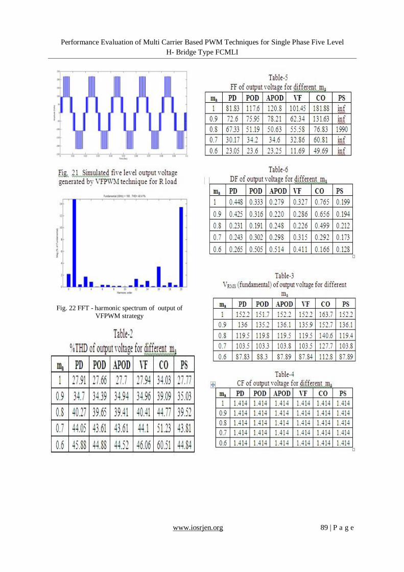
that the COPWM strategy produces significant 3rd and 20th harmonic energy. Fig.21 shows the five level output
voltage generated by VFPWM strategy and its FFT plot is shown in Fig.22. From Fig.22, it is observed that the
VFPWM strategy produces significant 18th and 20th harmonic energy.
The following parameter values are used for simulation: VDC=440V, fc=1100Hz and R (load) =100 ohms.
Fig. 12 FFT - harmonic spectrum of output of
PODPWM strategy
Performance Evaluation of Multi Carrier Based PWM Techniques for Single Phase Five Level
H- Bridge Type FCMLI
www.iosrjen.org 88 | P a g e
Fig. 13 Simulated five level output voltage
generated by APODPWM technique for R load
Fig. 14 FFT - harmonic spectrum of output of
APODPWM strategy
Fig. 15 Simulated five level output voltage
generated by PDPWM technique for R load
Fig. 16 FFT - harmonic spectrum of output of
PDPWM strategy
Fig. 17 Simulated five level output voltage
generated by PSPWM technique for R load
Fig. 18 FFT - harmonic spectrum of output of
PSPWM strategy
Fig. 19 Simulated five level output voltage
generated by COPWM technique for R load
Fig. 20 FFT - harmonic spectrum of output of
COPWM strategy
Performance Evaluation of Multi Carrier Based PWM Techniques for Single Phase Five Level
H- Bridge Type FCMLI
www.iosrjen.org 89 | P a g e
Fig. 22 FFT - harmonic spectrum of output of
VFPWM strategy
Performance Evaluation of Multi Carrier Based PWM Techniques for Single Phase Five Level
H- Bridge Type FCMLI
www.iosrjen.org 90 | P a g e
VI. CONCLUSION Single phase H-bridge type flying capacitor five level inverter employing different multi carrier single
reference modulation schemes has been investigated. It is found from Table 2 that PODPWM technique
provides output with relatively low distortion. COPWM technique is observed to perform better since it
provides relatively higher fundamental RMS output voltage (Table 3). Table 4 shows crest factor; Table 5
provides FF and Table 6 displays DF for all modulation indices. Appropriate PWM may be employed depending on the performance index required in a chosen application of MLI.
REFERENCES [1] Jae-hyun Jeon, Tae-Jin Kim, Dae-wook Kang, and Dong-seok Hyun, A Symmetric Carrier Technique of CRPWM for Voltage
Balance Method of Flying Capacitor Multi-level Inverter, IEEE Transactions on Industrial Electronics, Vol.52 , No. 3, June 2005, pp.
2759-2763.
[2] A. A. Boora, A. Nami, F. Zare, A. Ghosh and F. Blaabjerg, Voltage-Sharing Converter to Supply Single-Phase Asymmetrical Four-
Level Diode-Clamped Inverter With High Power Factor Loads, IEEE Transactions on Power Electronics, Vol. 25, No. 10, 2010, pp.
2507-2520.
[3] P. Panagis, F. Stergiopoulos, P. Marabeas and S. Manias, Comparison of State of the Art Multilevel Inverters, Procs IEEE Conference
on Power Electronics Specialists Conference 2008, pp. 4296-4301.
[4] L. M. Tolbert, J. N. Chiasson, Z. Du and K. J. McKenzie, Elimination of Harmonics in a Multilevel Converter with Nonequal DC
Sources, IEEE Transactions on Industry Applications, Vol. 41, No. 1, January/February 2005, pp. 75-81.
[5] A. Nami, F. Zare, A. Ghosh and F. Blaabjerg, A Hybrid Cascade Converter Topology With Series-Connected Symmetrical and
Asymmetrical Diode-Clamped H-Bridge Cells, IEEE Transactions on Power Electronics, Vol. 26, No.1, 2011, pp. 51-65.
[6] B.Shanthi and S.P.Natarajan, Comparative Study on Carrier Overlapping PWM Strategies for Five Level Flying Capacitor Inverter,
International Journal of Science and Techniques of Automatic control & Computer Engineering, IJ-STA, Vol.4, No.1, July 2010, pp.
1158-1173.
[7] T. Porselvi and R. Muthu, Comparison of Cascaded H-Bridge, Neutral Point Clamped and Flying Capacitor Multilevel Inverters Using
Multicarrier PWM, Proc. IEEE Conference (INDICON), 2011, pp. 1-4.
[8] L. Haiwen, L.M. Tolbert, S. Khomfoi, B.Ozpineci and D. Zhong , Hybrid Cascaded Multilevel Inverter with PWM Control Method,
Proc. Power Electronics Specialists Conference 2008, pp.1- 5.
[9] K. Ramani, Switching Pattern Selection Scheme Based 11 levels Flying Capacitor Multilevel Inverter fed Induction Motor, European
Journal of Scientific Research, Vol. 48,No. 1, 2010, pp. 51-62.
[10] A. Shukla, A. Ghosh and A. Josh, Flying Capacitor Multilevel Inverter and its Applications in Series Compensation of Transmission Lines, Proc. IEEE Power Engineering Society General Meeting, 2004, Vol.2, pp. 1453 -1458