Performance Evaluation of Wind Energy Conversion System using
Matrix Converter
Amit Kumar Sinha1, C.Hemalatha2, Mridul Pandey3, Dipayan Adhikary4
1 Research Scholar, Power Electronics 2 Assistant Professor, Department of Electrical and Electronics, Gnanamami College of Technology, Namakkal 3 Assistant Professor, Department of Electrical and Electronics, Gnanamami College of Technology, Namakkal
4 UG Scholar, Department of Electrical and Electronics, Gnanamami College of Technology, Namakkal
Abstract – For enhancing the power captured from the wind, the shaft speed need to be controlled. Power electronic converters are used to interface the induction generator with the grid and maximize the power captured from the wind. In this paper wind energy conversion system using the schemes based on back to back dual converter topology and the matrix converter topology are compared. Using the matrix converter, the terminal voltage and frequency of the induction generator can be controlled in such a way that the wind turbine is operating at its maximum power point for all wind velocities. The power factor at the interface with the grid is also controlled by the matrix converter to ensure purely active power injection into the grid for optimal utilization of the installed wind turbine capacity. Simulation results support the claims made on the advantages of the matrix converter scheme.
Key Words: Wind Energy Conversion System (WECS);
Double feed induction generator (DFIG); Matrix
converter (MC); Back to back converter; Maximum
power point tracking (MPPT).
1. INTRODUCTION Recent studies have found that the renewable integration impacts are non-zero and become more significant at higher size of penetrations. Integration of RESs into power system grids have impacts on optimum power flow, power quality, voltage and frequency control, system economics and load dispatch. The issues concerning the integration of renewable power generation in power systems are resolved using the power electronics [1]. Wind energy conversion system is largely using the doubly fed induction generators (DFIG) with back to back converters. The advantages of doubly fed induction generators (DFIGs) are also well known to us. DFIGs have major application for variable speed generation and are the most
important as well as popular generators for wind energy conversion system applications. In case of DFIG power converters are connected to the rotor side [2, 3]. Matrix converters (MCs) have many advantages, which are well documented in various research papers. The MC has become the preferred choice because of bidirectional power flow, sinusoidal input/output currents, and controllable input power factor [4]-[7]. On comparing the back-to-back converters with the MC, it is found that MC has some significant advantages over back to back converters. Due to the absence of electrolytic capacitors, the MC is potentially robust and reliable. The space occupied by an MC as compared to a conventional back-to- back converter is three times less [8]-[11]. Hence in WECS, the MC can be embedded. The matrix converter has the better performance in terms of maximum output current, especially in the low output frequency range in comparison to back to back converter. The reason of so low values of the output current for the back-to back converter is that, at low frequency, the output current is not equally shared among the six switches. On the contrary, the matrix converter is able to deliver high currents at low frequency because these currents are equally shared among the 18 switches.
In a grid-connected DFIG, back-to-back converters are used to connect the DFIG rotor to the utility. The rotor side converter controls the magnetizing and torque rotor currents. The grid side converter regulates the voltage in the dc bus of the back-to-back converters. The space vector modulation (SVM) is used to control the MC, hence regulating the rotor torque and magnetizing currents [12]-[15]. This paper proposes the replacement of back to back converter by and the matrix converter (MC) citing its advantages using simulated results in MATLAB. In the MC input side, a second-order LC power filter is used to improve the current waveform and reduce the input voltage distortion. Due to the excellent features like robustness, reduced size, and reliability, the MCs are best suited for wind energy conversion system applications.
In this paper various sections are being covered as follows. Section II will be discussing the back to back control systems. Section III will be discussing the MC with DFIG for WECS. In this section the vector control of DFIGs
International Research Journal of Engineering and Technology (IRJET) e-ISSN: 2395 -0056
is briefly reviewed. The dynamic performance of two control arrangements is assessed and the stability of the proposed control system is analyzed. In the Section IV simulation results are discussed and advantages of the proposed control system are appraised and presented in the Conclusion.
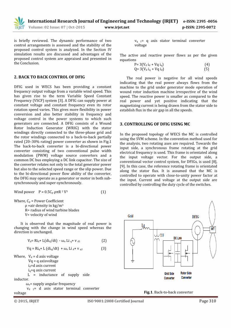
2. BACK TO BACK CONTROL OF DFIG DFIG used in WECS has been providing a constant frequency output voltage from a variable wind speed. This has given rise to the term Variable Speed Constant Frequency (VSCF) system [3]. A DFIG can supply power at constant voltage and constant frequency even its rotor rotation speed varies. This gives more flexibility in power conversion and also better stability in frequency and voltage control in the power systems to which such generators are connected. A DFIG consists of a Wound Rotor Induction Generator (WRIG) with the stator windings directly connected to the three-phase grid and the rotor windings connected to a back-to-back partially rated (20–30% rating) power converter as shown in Fig.1 The back-to-back converter is a bi-directional power converter consisting of two conventional pulse width modulation (PWM) voltage source converters and a common DC bus employing a DC link capacitor. The size of the converter relates not only to the total generator power but also to the selected speed range or the slip power. Due to the bi-directional power flow ability of the converter, the DFIG may operate as a generator or motor in both sub-synchronously and super-synchronously.
Wind power P = 0.5Cp ρπR 2 V3 (1) Where, Cp = Power Coefficient ρ =air density in kg/m3 R= radius of wind turbine blades V= velocity of wind
It is observed that the magnitude of real power is changing with the change in wind speed whereas the direction is unchanged.
Vd= Rid+ L(did/dt) - ωe Li q+ v d1 (2)
Vq = Riq+ L (diq/dt) + ωe Li d+ v q1 (3)
Where, Vd = d axis voltage Vq = q axisvoltage
id=d axis current iq=q axis current L = inductance of supply side inductor. ωe= supply angular frequency vd 1= d axis stator terminal converter voltage
vq 1= q axis stator terminal converter voltage
The active and reactive power flows as per the given equations P= 3(Vd id + Vq iq) (4) Q= 3(Vd iq + Vq id) (5) The real power is negative for all wind speeds indicating that the real power always flows from the machine to the grid under generator mode operation of wound rotor induction machine irrespective of the wind speed. The reactive power is smaller as compared to the real power and yet positive indicating that the magnetizing current is being drawn from the stator side to establish flux in the air gap in all the speeds.
3. CONTROLLING OF DFIG USING MC In the proposed topology of WECS the MC is controlled using the SVM scheme. In the convention method used for the analysis, two rotating axes are required. Towards the input side, a synchronous frame rotating at the grid electrical frequency is used. This frame is orientated along the input voltage vector. For the output side, a conventional vector control system, for DFIGs, is used [8], [9]. In this case, the reference rotating frame is orientated along the stator flux. It is assumed that the MC is controlled to operate with close-to-unity power factor at the input. Current and voltage at the output side are controlled by controlling the duty cycle of the switches.
Fig.1. Back-to-back converter
International Research Journal of Engineering and Technology (IRJET) e-ISSN: 2395 -0056
The relations between voltage and current are justified by following equations. VABC = S. Vabc (6) Iabc= ST. IABC (7) Where, VABC = Output Voltage Vabc = Input Voltage IABC = Output Current Iabc = Input Current S11 S12 S13 S= S21 S22 S23 S31 S32 S33 S11 – S33 is duty cycle of corresponding switches of matrix converter.
DFIG model of WECS using MC control topology used in this paper is shown in Fig.2. A second-order L–C filter is used at the input to filter out the supply side harmonics and ensures the sinusoidal input current hence improve the quality of the current. The grid is represented by a voltage source and a series impedance. The MC feeds the rotor; the stator is connected to the grid. However, to implement the vector control of DFIGs, the stator voltage is measured to obtain the stator flux. The MC input voltage is used in the SVM algorithm, additional voltage transducers or a stator voltage observer is required in the system of Fig. 2. The advantages are that no additional voltage transducers are required and the stability of the proposed WECS is improved. It draws sinusoidal input current and, depending on the modulation technique, it can be arranged so that unity displacement factor is seen at the supply side irrespective of the type of load.
Fig. 2. Matrix Converter topology
The proposed system has been simulated and no hardware experimentation is carried out on prototypes to fully verify the practicality of the proposed system. 4. SIMULATION STUDY
The proposed topology using back to back and matrix converters described above is simulated using MATLAB for the DFIG operation in a WECS for different wind velocities for the system to function in both sub-synchronous as well as super-synchronous speeds. The generator speed is adjusted such that maximum power can be harnessed at a given wind velocity.
Fig.3.Wind Energy Conversion System model using back to back converter.
4.1 Comparative Study of WECS using MC and back-to-back converter Wind energy conversion system models are developed using back to back converter and the matrix converter with DFIG in Fig.4 and Fig.5. DFIG is operated in generating mode for wide range of wind velocity and the power is flown from WECS to the grid in both topologies.
International Research Journal of Engineering and Technology (IRJET) e-ISSN: 2395 -0056
Fig.4.Wind Energy Conversion System model using matrix converter. 4.2 Results
As seen from the Fig.5, Fig.6 &Fig.7 the stator current is stabilizing in 0.2 seconds when matrix converter is employed with DFIG of WECS. While analyzing the Fig.12 & Fig.13 time taken by the system using back to back converter is more than 0.6 seconds. This shows that Using MC with DFIG in WECS the net performance of the system improves. It ensures the continuous flow of power from the machine to the grid. Satisfactory current and voltage profile is achieved as compared with the back to back converter. Various parameters output achieved using MC are given as follows Fig. 5. Stator Current a (pu) using Matrix Converter.
Fig.6.Stator Current b (pu) using Matrix Converter.
Fig.7.Stator Current c (pu) using Matrix Converter.
The results of simulation shows that the WECS is always generating the power hence connected with the grid. Power is flowing from WECS to the connected grid. Hence using the MC with DFIG in WECS improves the net performance of the system.
Fig. 8. Rotor Speed (m/s).
Fig.9. Electromagnetic torque (Nm) using Matrix Converter.
International Research Journal of Engineering and Technology (IRJET) e-ISSN: 2395 -0056
Fig.10. Rotor side voltage ( V_abc) using Matrix Converter. Fig. 11. Stator voltage (V_abc) (pu) using Matrix Converter Fig. 12. Stator Current_a (pu) using back to back converter.
Fig. 13. Stator voltage ( V_abc) (pu) using back to back
converter.
5. CONCLUSIONS
WECS using DFIG models are developed and simulated using back to back converter and the matrix converter in MATLAB. DFIG for both topologies using back to back converter and the matrix converter operated in generating mode for the wide range of the wind velocity. Stator current stability, stator voltage and machine torque for both cases have been compared. It is concluded that system takes three times less time to stabilize when matrix converter is used in comparison to back to back converter. Torque quality and voltage stability is better in matrix converter as compared to back to back fed DFIG. Hence, matrix converter is more suitable for application in the wind energy conversion system which is getting advanced day by day using advanced power electronics.
REFERENCES [1] S. Nishikata and F. Tatsuta, ―A new interconnecting
method for wind turbine/generators in a wind farm and basic performances of the integrated system, IEEE Trans. Ind. Electron., vol. 57, no. 2, pp. 468– 475, Feb. 2010.
[2] R. Pena, I.e. Clare, and G. M. Asher, "Doubly fed
induction generator using back-to-back PWM converters and its application to variable speed wind-energy generation ", lEE Proc. Electr. Power Appl., Vol. 143, No. 3, pp. 231-241, May 1996.
[3] T. Friedli and J. W. Kolar, ―Comprehensive
comparison of three-phase ac–ac matrix converter and voltage dc-link back-to-back converter systems,‖ in Proc. IPEC, Jun. 21–24, 2010, pp. 2789–2798.
[4] P. Wheeler, J. Rodriguez, J. Clare, L. Empringham, and
A. Weinstein, ―Matrix converters: A technology review,‖IEEE Trans. Ind. Electron., vol. 49, no. 2, pp. 276–288, Apr. 2002.
[5] L. Wei, T. A. Lipo, and H. Chan, ―Matrix converter
topologies with reduced number of switches,‖ in Proc. VPEC Power Electron. Sem., Apr. 14–18, 2002, pp. 57–63.
[6] S. Kim, S.-K. Sul, and T. A. Lipo, ―AC/AC power
conversion based on matrix converter topology with unidirectional switches IEEE Trans .Ind. Appl., vol. 36, no. 1, pp. 139–145, Jan./Feb. 2000.
International Research Journal of Engineering and Technology (IRJET) e-ISSN: 2395 -0056
[9] R. Vargas, U. Ammann, and J. Rodriguez, ―Predictive approach to increase efficiency and reduce switching losses on matrix converters, IEEE Trans. Power Electronics., vol. 24, no. 4, pp. 894–902, Apr. 2009.
[10] M. Nguyen, H. Lee, and T. Chun, ―Input power factor
compensation algorithms using a new direct-SVM method for matrix converter, IEEE Trans. Ind. Electron., vol. 58, no. 1, pp. 232–243, Jan. 2011.
[11] R. Cardenas, R. Pena, P. Wheeler, J. Clare, and G.
Asher, ―Control of the reactive power supplied by a WECS based on an induction generator fed by a matrix converter, IEEE Trans. Ind. Electron., vol. 56, no. 2, pp. 429–438, Feb. 2009.
[12] D. Casadei, G. Serra, A. Tani, and L. Zarri, ―Matrix
converter modulation strategies: A new general approach based on space-vector representation of the switch state, IEEE Trans. Ind. Electron., vol. 49, no. 2, pp. 370– 381, Apr. 2002.
[13] P. W. Wheeler, J. Clare, and L. Empringham,
―Enhancement of matrix converter output waveform quality using minimized commutation times, IEEE Trans. Ind. Electron., vol. 51, no. 1, pp. 240–244, Feb. 2004.
[14] H. Hojabri, H. Mokhtari, and L. Chang, ―A generalized
technique of modeling, analysis, and control of a matrix converter using SVD,IEEE Trans. Ind. Electron., vol. 58, no. 3, pp. 949–959, Mar. 2011.
[15] R. Cardenas, R. Pena, P. Wheeler, and J. Clare,
―Experimental validation of a space-vector-modulation algorithm for four-leg matrix converters, IEEE Trans. Ind. Electron., vol. 58, no. 4, pp. 1282–1293, Apr. 2011.
BIOGRAPHIES
Amit Kumar Sinha was born in India, in 1991. He received B.E(Electrical and Electronics) degree from Meenakshi University, India in 2012 and M.E (Power Electroics and Drives) from Anna University,India in 2014. His area of intrest includes Power electronics, Electrical Machines and Power Quality.
C. Hemalatha was born in India, in 1982. She received B.E(Electrical and Electronics) degree from Periyaar University, India in 2003 and M.E.( Applied Electronics) from Anna University, India in 2011. Her area of interest includes Control System and Power System.
Mridul Pandey was born in India, in 1989. He received B.E(Electrical and Electronics) degree from Anna University, Chennai,India in 2010 and M.Tech (Process Control And Instrumentation) from SASTRA University, India in 2012. His area of interest includes Control System and Electronic Device and Circuit.