selection of the optimum size of the accumulator as the only energy source for a plant for a definite time interval. Puddu and Paderi /10/ have investigated the discrepancies in the thermal behaviour of ideal and real gases to determine their effects on the processes of expansion and compression of an accumulator. The performance characteristics of a hydro-pneumatic type accumulator on the responses of the hydrostatic drive used in off-road vehicles are studied in this article. The efficiency of a hydrostatic drive system depends greatly on the load conditions, showing significantly low efficiency under partial load conditions, which arises when either the desired velocity or torque is much less than its maximum value. Accumulators are used in the hydraulic system to reduce pressure pulsations, emergency operation, energy storage, surge absorption, potential energy regeneration, dampening vibrations and several other applications /11/. Energy is stored in the hydraulic accumulator by the volume of the hydraulic fluid that compresses the gas under pressure. The rate at which the compression and expansion of the gas takes place affects the gas state – which is defined by volume, pressure and temperature /12/. The hydraulic accumulator is one of the hydraulic elements of the system that will be used to reduce pressure and speed pulsation inside it; thus, the selection and workflow modelling have a significant influence on the stability of the entire system. For proper selection of accumulators, the understanding of its dynamic phenomena is essential. This paper deals with the issue of understanding the dynamic phenomena in bladder- type accumulators by controlling its various performance parameters. The analysis has been done using two different sizes of accumulators. Using the mathematical model, MATLAB/Simulink ® environment and DSH ® software, simulation model of the physical system is made. By varying the capacity and precharge pressure of the hydraulic accumulator and load torque using the pump loading configuration on the hydro-motor, the performance behaviour of the accumulator is determined. The simulation results are verified wi th the experimental test data. Using the validated model, the parametric studies are also made to rationalize the system design. The studies made in this article may be useful for the proper selection of accumulators with respect to its physical attributes for use in hydrostatic drive system in typical mining equipment. 1.1 Principle of Operation of a Hydro-pneumatic Accumulator The hydro-pneumatic type accumulator consists of a synthetic polymer rubber bladder like chloroprene, nitrile, etc. inside a metal (steel) shell. The bladder is filled with compressed gas. A poppet valve located at the discharge port closes the port when accumulator is completely discharged that keeps the bladder from getting out into the system. The operation of a bladder type hydraulic accumulator is explained below. Figure 1 shows the schematic representation of the working of a hydraulic accumulator. Figure 1: Schematic representation of the working of a bladder type hydraulic accumulator. Referring to Figure 1, Ppr = Precharge pressure, P1 = Maximum working pressure, P2 = Minimum working pressure, V1 = Volume of the fluid chamber during Precharged condition, V2 = Volume of the fluid chamber after charging, V3 = Volume of the fluid chamber after discharging. The bladder of the accumulator and the accumulator shell, both have nearly the same volume when precharged with Nitrogen gas (Ppr) to a predetermined pressure. The pressurized fluid supplied by the pump cannot enter the accumulator shell until the system pressure exceeds the precharge pressure of the gas in the accumulator bladder. As the system pressure increases above the precharge pressure, the fluid enters the accumulator and compresses the bladder until gas and system pressure become stabilized at P1, which is typically the set pressure of main PRV (Pressure Relief Valve) of the hydraulic set-up or maximum working pressure of the hydraulic system. The Performance Investigation of a Hydro-pneumatic type Accumulator used in a Hydrostatic Drive System of Off-road Vehicles Ajit Kumar, K. Dasgupta, J. Das Department of Mining Machinery Engineering Indian Institute of Technology (Indian School of Mines) Dhanbad, Jharkhand, India E-Mail: [email protected], [email protected], [email protected]The performance characteristics of a hydro-pneumatic type accumulator on the responses of the hydrostatic drive system are studied in this article. The physical system considered for the analysis consists of fixed displacement pump, hydro-motor coupled with a loading unit and an accumulator. By varying the capacity and precharge pressure of the hydraulic accumulator and load torque on the hydro-motor, the performance behaviour of the accumulator is determined. In MATLAB/Simulink® environment, the simulation studies are made. By comparing the simulation results with the test data, the model is validated. The studies made in this article may be useful for the proper selection of accumulators in typical mining equipment. Keywords: Hydro-pneumatic type accumulator, MATLAB/Simulink ® environment, performance characteristics, hydrostatic drive. Target audience: Mobile Hydraulics, Mining and allied Industry, Design Process 1 Introduction Efficient performance and energy saving in construction and mining machinery has become a preeminent issue due to the increase in fuel price and increasing demand of production. Hydraulic systems are predominantly used in several industrial applications and are indispensable for mobile equipment used in mining operations. Commonly, in a typical working cycle of mining equipment the potential energy and the kinetic energy are dissipated in form of heat. So it is required to make maximum use of regenerative energy for further improvement of fuel consumption and also to ensure higher system control performance. One of the possible solutions is the incorporation of hydraulic accumulators in a hydraulic main. Some of the significant research works made in this area in recent past are discussed here. An energy regeneration system in hydraulic forklift trucks has been studied, concentrating on energy recovery in the main lift system with electric motor and batteries, and resulting in improved energy efficiency but shorter lifetime of components /1/. An energy recovery system with a hydraulic accumulator that could save and restore energy in a crane’s hydraulic system has also been studied, and it was found that the potential energy of the crane and load can be saved in the form of hydraulic energy and reutilized /2/. A speed control system of a variable voltage variable frequency hydraulic elevator with a pressure accumulator has been studied, and shown to have higher efficiency compared with a hydraulic elevator without a pressure accumulator /3/. An energy saving hydrostatic transmission (HST) system using accumulator has been investigated through modelling and simulation with regard to the testing of primary energy sources and augmenting the energy saving possibilities of the system /4/. The findings of the said analysis indicate that the low efficiency of conventional hydrostatic transmission systems under partial load conditions can be enhanced by using the accumulator. The energy efficiency dependency of the accumulator has been investigated and compared to ideal gas thermodynamic processes in term of its time constant, time of storage, frequency of load /5, 6/. In a sub-system, accumulator is used as a critical item of the energy regenerative modelling, which can be coupled to or decoupled from the HST system to enhance the system performance efficiency /7, 8/. Prodan et al. /9/ have presented a mathematical model for the 37 GROUP A - 3
Transcript
The 11th International Fluid Power Conference, 11. IFK, March 19-21, 2018, Aachen, Germany
selection of the optimum size of the accumulator as the only energy source for a plant for a definite time interval. Puddu and Paderi /10/ have investigated the discrepancies in the thermal behaviour of ideal and real gases to determine their effects on the processes of expansion and compression of an accumulator. The performance characteristics of a hydro-pneumatic type accumulator on the responses of the hydrostatic drive used in off-road vehicles are studied in this article. The efficiency of a hydrostatic drive system depends greatly on the load conditions, showing significantly low efficiency under partial load conditions, which arises when either the desired velocity or torque is much less than its maximum value. Accumulators are used in the hydraulic system to reduce pressure pulsations, emergency operation, energy storage, surge absorption, potential energy regeneration, dampening vibrations and several other applications /11/. Energy is stored in the hydraulic accumulator by the volume of the hydraulic fluid that compresses the gas under pressure. The rate at which the compression and expansion of the gas takes place affects the gas state – which is defined by volume, pressure and temperature /12/. The hydraulic accumulator is one of the hydraulic elements of the system that will be used to reduce pressure and speed pulsation inside it; thus, the selection and workflow modelling have a significant influence on the stability of the entire system. For proper selection of accumulators, the understanding of its dynamic phenomena is essential. This paper deals with the issue of understanding the dynamic phenomena in bladder- type accumulators by controlling its various performance parameters. The analysis has been done using two different sizes of accumulators. Using the mathematical model, MATLAB/Simulink® environment and DSH® software, simulation model of the physical system is made. By varying the capacity and precharge pressure of the hydraulic accumulator and load torque using the pump loading configuration on the hydro-motor, the performance behaviour of the accumulator is determined. The simulation results are verified with the experimental test data. Using the validated model, the parametric studies are also made to rationalize the system design. The studies made in this article may be useful for the proper selection of accumulators with respect to its physical attributes for use in hydrostatic drive system in typical mining equipment.
1.1 Principle of Operation of a Hydro-pneumatic Accumulator
The hydro-pneumatic type accumulator consists of a synthetic polymer rubber bladder like chloroprene, nitrile, etc. inside a metal (steel) shell. The bladder is filled with compressed gas. A poppet valve located at the discharge port closes the port when accumulator is completely discharged that keeps the bladder from getting out into the system. The operation of a bladder type hydraulic accumulator is explained below. Figure 1 shows the schematic representation of the working of a hydraulic accumulator.
Figure 1: Schematic representation of the working of a bladder type hydraulic accumulator.
Referring to Figure 1, Ppr = Precharge pressure, P1 = Maximum working pressure, P2 = Minimum working pressure, V1 = Volume of the fluid chamber during Precharged condition, V2 = Volume of the fluid chamber after charging, V3 = Volume of the fluid chamber after discharging.
The bladder of the accumulator and the accumulator shell, both have nearly the same volume when precharged with Nitrogen gas (Ppr) to a predetermined pressure. The pressurized fluid supplied by the pump cannot enter the accumulator shell until the system pressure exceeds the precharge pressure of the gas in the accumulator bladder. As the system pressure increases above the precharge pressure, the fluid enters the accumulator and compresses the bladder until gas and system pressure become stabilized at P1, which is typically the set pressure of main PRV (Pressure Relief Valve) of the hydraulic set-up or maximum working pressure of the hydraulic system. The
The 11th International Fluid Power Conference, 11. IFK, March 19-21, 2018, Aachen, Germany
Performance Investigation of a Hydro-pneumatic type Accumulator used in a Hydrostatic Drive System of Off-road Vehicles
Ajit Kumar, K. Dasgupta, J. Das
Department of Mining Machinery Engineering Indian Institute of Technology (Indian School of Mines) Dhanbad, Jharkhand, India
The performance characteristics of a hydro-pneumatic type accumulator on the responses of the hydrostatic drive system are studied in this article. The physical system considered for the analysis consists of fixed displacement pump, hydro-motor coupled with a loading unit and an accumulator. By varying the capacity and precharge pressure of the hydraulic accumulator and load torque on the hydro-motor, the performance behaviour of the accumulator is determined. In MATLAB/Simulink® environment, the simulation studies are made. By comparing the simulation results with the test data, the model is validated. The studies made in this article may be useful for the proper selection of accumulators in typical mining equipment.
Keywords: Hydro-pneumatic type accumulator, MATLAB/Simulink® environment, performance characteristics, hydrostatic drive. Target audience: Mobile Hydraulics, Mining and allied Industry, Design Process
1 Introduction
Efficient performance and energy saving in construction and mining machinery has become a preeminent issue due to the increase in fuel price and increasing demand of production. Hydraulic systems are predominantly used in several industrial applications and are indispensable for mobile equipment used in mining operations. Commonly, in a typical working cycle of mining equipment the potential energy and the kinetic energy are dissipated in form of heat. So it is required to make maximum use of regenerative energy for further improvement of fuel consumption and also to ensure higher system control performance. One of the possible solutions is the incorporation of hydraulic accumulators in a hydraulic main.
Some of the significant research works made in this area in recent past are discussed here. An energy regeneration system in hydraulic forklift trucks has been studied, concentrating on energy recovery in the main lift system with electric motor and batteries, and resulting in improved energy efficiency but shorter lifetime of components /1/. An energy recovery system with a hydraulic accumulator that could save and restore energy in a crane’s hydraulic system has also been studied, and it was found that the potential energy of the crane and load can be saved in the form of hydraulic energy and reutilized /2/. A speed control system of a variable voltage variable frequency hydraulic elevator with a pressure accumulator has been studied, and shown to have higher efficiency compared with a hydraulic elevator without a pressure accumulator /3/. An energy saving hydrostatic transmission (HST) system using accumulator has been investigated through modelling and simulation with regard to the testing of primary energy sources and augmenting the energy saving possibilities of the system /4/. The findings of the said analysis indicate that the low efficiency of conventional hydrostatic transmission systems under partial load conditions can be enhanced by using the accumulator. The energy efficiency dependency of the accumulator has been investigated and compared to ideal gas thermodynamic processes in term of its time constant, time of storage, frequency of load /5, 6/. In a sub-system, accumulator is used as a critical item of the energy regenerative modelling, which can be coupled to or decoupled from the HST system to enhance the system performance efficiency /7, 8/. Prodan et al. /9/ have presented a mathematical model for the
37
GR
OU
P A
- 3
The 11th International Fluid Power Conference, 11. IFK, March 19-21, 2018, Aachen, Germany
unloading the main pump i.e. by switching off the unloading PRV (9) simultaneously, the flow was supplied to the hydro-motor from the accumulator.
The experiments were performed in a well-ventilated lab. In order to keep the viscosity of the oil constant with reasonable accuracy, the test set-up is fitted with appropriate oil cooler to maintain the temperature at 55 ± 2° C. The pressures, flow rates and the speed of the hydro-motor were measured through respective sensors and recorded through data logger /13/. To examine the repeatability of the system, the experiments were conducted several times before collecting the test data. Table 1 list the major components and instruments used in the test set-up.
Table 1: List of the major components and instruments used in the physical system.
3 System Modelling
Referring to Figure 2, the model of the test set-up is discussed in this section considering the actual features of the critical components used in the physical system. While developing the model, following assumptions are made:
• The detail dynamics of the pump, hydro-motor and the valves are ignored,
• The gas compression of the accumulator bladder is determined on the basis of the thermodynamic behaviour of ideal gases,
• The charging and discharging processes of accumulator are assumed to be polytropic,
• Losses in the accumulator due to heat transfer are ignored,
• Fluid compressibility is not taken into account. The fluid considered has Newtonian characteristics.
3.1 Mathematical Model
In order to perform a dynamic simulation of the system, the mathematical model of the system is developed defining the behaviour of the critical components.
1. Fixed-Displacement Pump. The pump flow rate is given by
𝑞𝑞𝑃𝑃 = 𝐷𝐷𝑃𝑃 𝜔𝜔𝑃𝑃 − 𝑘𝑘𝑙𝑙𝑙𝑙𝑙𝑙𝑙𝑙 Δ𝑃𝑃𝑃𝑃 (1)
where 𝑘𝑘𝑙𝑙𝑙𝑙𝑙𝑙𝑙𝑙 = 𝐾𝐾𝐻𝐻𝐻𝐻𝜈𝜈 ρ (2)
Sl. No.
Items Specifications Make and Model
1. Hydraulic vane pump
Displacement: 19.8 cc/ rev Max. pressure: 150 bar
Yuken Kogyo Co. Ltd., Japan; PV2R119FRA1080
2. Hydraulic Accumulator
Bladder Type Capacity: 20 l and 10 l
Parker Hannifin Corporation, USA; BA05B5T01A1
3. Hydro-Motor Fixed Displacement Bent Axis Motor Displacement: 12 cc/ rev Max. pressure: 150 bar
The 11th International Fluid Power Conference, 11. IFK, March 19-21, 2018, Aachen, Germany
volume now stored in the accumulator becomes V2. After the poppet valve is opened, the pressurized fluid of volume V2 stored in the accumulator drives the hydro-motor. The system pressure reduces as the energy stored in the form of pressurized fluid is released to drive the hydro-motor; the accumulator bladder expands releasing the stored volume and the system pressure drops to P2 which is typically the minimum operating pressure of the system to drive the hydro-motor. At this typical minimum operating pressure of the system, the volume of the pressurized fluid stored in the accumulator is V3 which drives the hydro-motor at a constant pressure of P2. After the fluid stored in the accumulator gets exhausted, the hydro-motor speed gradually falls to zero.
2 Experimental Test Set-up
The schematic representation of the experimental test set-up is shown in Figure 2 and its pictorial view is depicted in Figure 3.
Figure 2: Schematic representation of the physical system incorporating hydro-pneumatic type accumulator.
(a) Front view (b) Rear View
Figure 3: Pictorial view of the experimental set-up showing front and rear view.
A 7.5 kW electric motor (1) drives a fixed displacement vane pump (2) that supplies pressurized fluid to the accumulators (3) of capacities 20 ltr and 10 ltr through check valve (4). The pump flow is also supplied to the bent axis hydro-motor (5) through solenoid operated proportional flow control valve (6). By adjusting the command signal (from 0 – 10 V dc) given to the flow control valve, the pump flow supplied to the hydro-motor is varied; thereby the speed of the hydro-motor is controlled. The motor in-turn drives a fixed displacement pump (7) in the loading circuit that supplies flow to the sump through a PRV (8). By regulating the set pressure of the PRV, the load torque on the hydro-motor shaft is controlled. Before the pump supply is made available to the hydro motor, both the accumulators were charged by opening their respective poppet valves and closing the proportional flow control valve. After they are fully charged, the poppet valves were switched off and the opening of the flow control valve was set at a maximum flow rate. Then by switching on the poppet valves and
39
GR
OU
P A
- 3
The 11th International Fluid Power Conference, 11. IFK, March 19-21, 2018, Aachen, Germany
Figure 4: Simulation graphics of the hydraulic test rig created using DSH software.
Figure 5: Simulation model of the hydraulic system.
4 Results and Discussions
The analysis is performed to investigate the performance behaviour of a hydro-pneumatic type accumulator used in hydrostatic drive of off-road vehicles on the responses of hydro-motor speed. Using the experimental set-up discussed in section 2, the experiments were performed. After the accumulators were fully charged at a particular precharge pressure, the cartridge valves were opened instantaneously to supply pressurized flow to the hydro-motor and the performance characteristics of accumulator were studied. Comparisons between simulation and experimental results are made for the dynamic performance of the accumulator discharge on the drive system at different load pressure using 10 litres and 20 litres capacity accumulators. The results are shown in Figures 6 and 7. The validation of the model is also made by comparing the simulation and experimental results for the accumulator discharge pressure at different resistive loads and capacities of the accumulator as shown in Figures 8 and 9.
The 11th International Fluid Power Conference, 11. IFK, March 19-21, 2018, Aachen, Germany
2. Accumulator. Hydro-pneumatic type accumulators of capacities 20 litres and 10 litres are used in the physical system for analysis. The rate of change of accumulator absolute pressure is given by /14/
�̇�𝑃𝑎𝑎 = 𝛽𝛽𝜌𝜌 [ 𝜌𝜌 𝑞𝑞𝑎𝑎𝑎𝑎𝑎𝑎 𝑉𝑉𝐹𝐹⁄
1+𝛽𝛽𝜌𝜌 𝜌𝜌 𝑉𝑉𝑎𝑎
𝛾𝛾 𝑃𝑃𝑎𝑎 𝑉𝑉𝐹𝐹
] (3)
The accumulator is considered to be working in an adiabatic process. The value of the polytropic index is determined and discussed in Appendix I. The oil flow rate discharged by the accumulator is expressed as;
𝑞𝑞𝑎𝑎𝑎𝑎𝑎𝑎 = 𝑑𝑑𝑉𝑉𝑎𝑎𝑑𝑑𝑑𝑑 = − 𝑉𝑉𝑎𝑎 𝑑𝑑𝑃𝑃𝑎𝑎
𝑑𝑑𝑑𝑑1.72 𝑃𝑃𝑎𝑎
(4)
3. Hydro-motor and Loading system. Fixed displacement bent axis hydro-motor is used in the proposed system. The describing equations of the hydro-motor considered for the analysis are expressed below.
The inlet flow to the hydro-motor is expressed as;
𝑞𝑞𝑀𝑀 = 𝐷𝐷𝑀𝑀 𝑑𝑑𝜃𝜃𝑀𝑀𝑑𝑑𝑑𝑑 + 𝐶𝐶𝑙𝑙𝑙𝑙 Δ𝑃𝑃𝐿𝐿 + 𝑉𝑉𝑀𝑀
𝛽𝛽 𝑑𝑑Δ𝑃𝑃𝐿𝐿𝑑𝑑𝑑𝑑 (5)
The torque load on the hydro-motor is given by;
𝑇𝑇𝑑𝑑ℎ = 𝐽𝐽𝑀𝑀 𝛼𝛼𝑀𝑀 + 𝐵𝐵𝑀𝑀 𝜔𝜔𝑀𝑀 + 𝑇𝑇𝐿𝐿 (6)
where load torque 𝑇𝑇𝐿𝐿 is given by;
𝑇𝑇𝐿𝐿 = 𝐷𝐷𝑃𝑃𝐿𝐿 Δ𝑃𝑃𝑃𝑃𝐿𝐿 (7)
The value of MB is determined by investigating the steady state characteristics of the hydro-motor as studied by
N. Kumar et al. /15/.
4. Control Valves. With the movement of the valve spool due to the pressure acting on it, the valve port starts opening at its cracking/set pressure and at the full open pressure, the movement of the valve spool is arrested. The model of the control valves considers for both the laminar and turbulent flow states by analysing the Reynolds number (Re) and correlating its value with the critical Reynolds number (Recr). The flow rate 𝑞𝑞𝐶𝐶𝑉𝑉 across the control valves is determined by the following equations.
The proposed physical system is modelled in MATLAB/Simulink® environment using sim-hydraulics blocks and DSH software. The model block consists of basic components like pump block connected with a variable angular velocity source, accumulator block, hydro-motor block and valve blocks. The output of sine wave is given to variable angular velocity source to introduce the pressure-surge in the system. A PRV is set across the main pump to relieve excess pressure of system. The upstream pressure comes in the form of pulsation which is sensed by pressure sensor. A flow sensor is also connected in system line to check flow ripple. Accumulator is installed between the pump and hydro-motor line to absorb pressure pulsation.
Referring to the physical system discussed in section 2, the DSH model and simulation model of the proposed system is shown in Figure 4 and Figure 5. The parametric values of the major components of the physical system are taken from the datasheet of the components specified in Table 1. The features pertinent to each component are explicitly detailed in the Sim-Hydraulics component library /16/.
41
GR
OU
P A
- 3
The 11th International Fluid Power Conference, 11. IFK, March 19-21, 2018, Aachen, Germany
of 10l and 2257 rpm in case of 20l accumulator whereas for load given by 80 bar set pressure of PRV of the loading circuit, it starts from 759 rpm in case of 10l and 1008 rpm for 20l accumulator. Referring to Figure 6, in case of smaller load, by the time the speed of the hydro-motor decreases from 1750 rpm to 1208 rpm at 5.22s, the energy stored in the accumulator is almost exhausted and thereafter its speed falls abruptly in 2.78s. In case of higher load, the maximum speed of the hydro-motor starts from a lower value of 759 rpm. After the speed decreases from 759 rpm to 300 rpm in 7.9s, considerable amount of energy remains in the accumulator. The remaining stored energy drives the hydro-motor from 7.9s to 42.7s almost at a speed of 185 rpm for the constant load applied on it by the 80 bar pressure in the loading circuit. In case of 20l accumulator for the same loading conditions and precharge pressure, as the larger amount of energy is stored in the accumulator compared to 10l capacity accumulator, the running time of the hydro-motor increases. The deviation observed between the experimental and the simulation results in Figures 5 and 6 at lower hydro-motor speed may be due to the characteristics of the PRV of the loading circuit at low flow range. However, the simulation and experimental responses are very similar in nature. The percentage variation between the simulation and the experimental results is within ± 3% to 5%. Due to the minor fluctuations of the actual speed compared to the simulation results and the measured noise of the speed sensors, the smooth curves of the experimental responses could not be obtained. The Coulomb friction/ Stiction effect could not be realized that would have been expected at lower speed. However, the close agreement between the predicted and the experimental responses of the system validates the model.
Figure 8: Variation of discharge pressure for 10 litres accumulator at different resistive loads.
Figure 9: Variation of discharge pressure for 20 litres accumulator at different resistive loads.
Characteristics of the variation of the discharge pressure of the accumulators are also studied for two different sizes of the accumulators at different loading pressures during the time accumulator decays and are shown in Figures 8 and 9. With the increase in the resistive load (50 bar to 80 bar set pressure) controlled through PRV of the loading circuit, the discharge pressure increases. The characteristics follow mostly the polytropic process of expansion of the gas in the accumulator during the discharge process (Appendix I).
The 11th International Fluid Power Conference, 11. IFK, March 19-21, 2018, Aachen, Germany
Figure 6: Comparison of the simulation and the experimental results of the hydro-motor speed for 10 litres accumulator.
Figure 7: Comparison of the simulation and the experimental results of the hydro-motor speed for 20 litres accumulator.
Figures 6 and 7 compare the experimental and the simulation results for the hydro-motor speeds. The time delay (td) shown in Figures 6 and 7 is the time required to open the cartridge valve. By comparing the simulation and experimental results for 10 l accumulator shown in Figure 6, it is found that the peak time, tp(exp) for the experimental result is 0.20s for 50 bar and 0.22s for 80 bar loading pressure which is higher than that of the simulation result (tp(sim)). This is due to the damping effects that are not considered in the model; like, seal friction of the hydro-motor. With the increase in the load resistance (50 bar to 80 bar set pressure) controlled through PRV of the loading circuit discussed in section 2, the steady state pressure of the physical system rises and the maximum speed of the hydro-motor falls from 1750 rpm to 759 rpm. For the identical load resistances, the hydro-motor speeds are also compared for 20 litres capacity of the accumulator and it is shown in Figure 7. With the opening of the cartridge valve, there is instantaneous flow supplied from the accumulator to the hydro-motor. Therefore, there is sudden rise in the speed of the hydro-motor. The overshoot of the hydro-motor speed depends on the effective bulk modulus of the fluid in the line connecting the accumulator and the hydro-motor as well as the load inertia on the motor shaft. Once the inertia is overcome, the hydro-motor speed decreases from its peak value following mostly the polytropic process of expansion of the gas in the accumulator. In case of 50 bar set pressure of PRV in the loading circuit, the discharge of the fluid from the accumulator drives the motor for the time up to 7.5s as shown in Figure 6. With the release of the fluid from the accumulator, its pressure reduces, the hydro-motor speed also decays till 5.22s and thereafter the speed falls to zero in 2.24s. Similar trend is observed for the load resistance given by 80 bar pressure of the loading circuit where the speed of the hydro-motor falls from its maximum value of 759 rpm to 185 rpm in 42.7s and thereafter the speed fall to zero in 2.54s.
The energy stored for a particular capacity of the accumulator was same for the same precharge pressure driving different loads. Therefore, in the event of the opening of the cartridge valve, the pressurized fluid of the accumulator drives the hydro-motor at a higher speed for the smaller load (50 bar set pressure of the loading circuit). It is shown in Figures 6 and 7 that the hydro-motor speed for smaller load starts from 1750 rpm in case
43
GR
OU
P A
- 3
The 11th International Fluid Power Conference, 11. IFK, March 19-21, 2018, Aachen, Germany
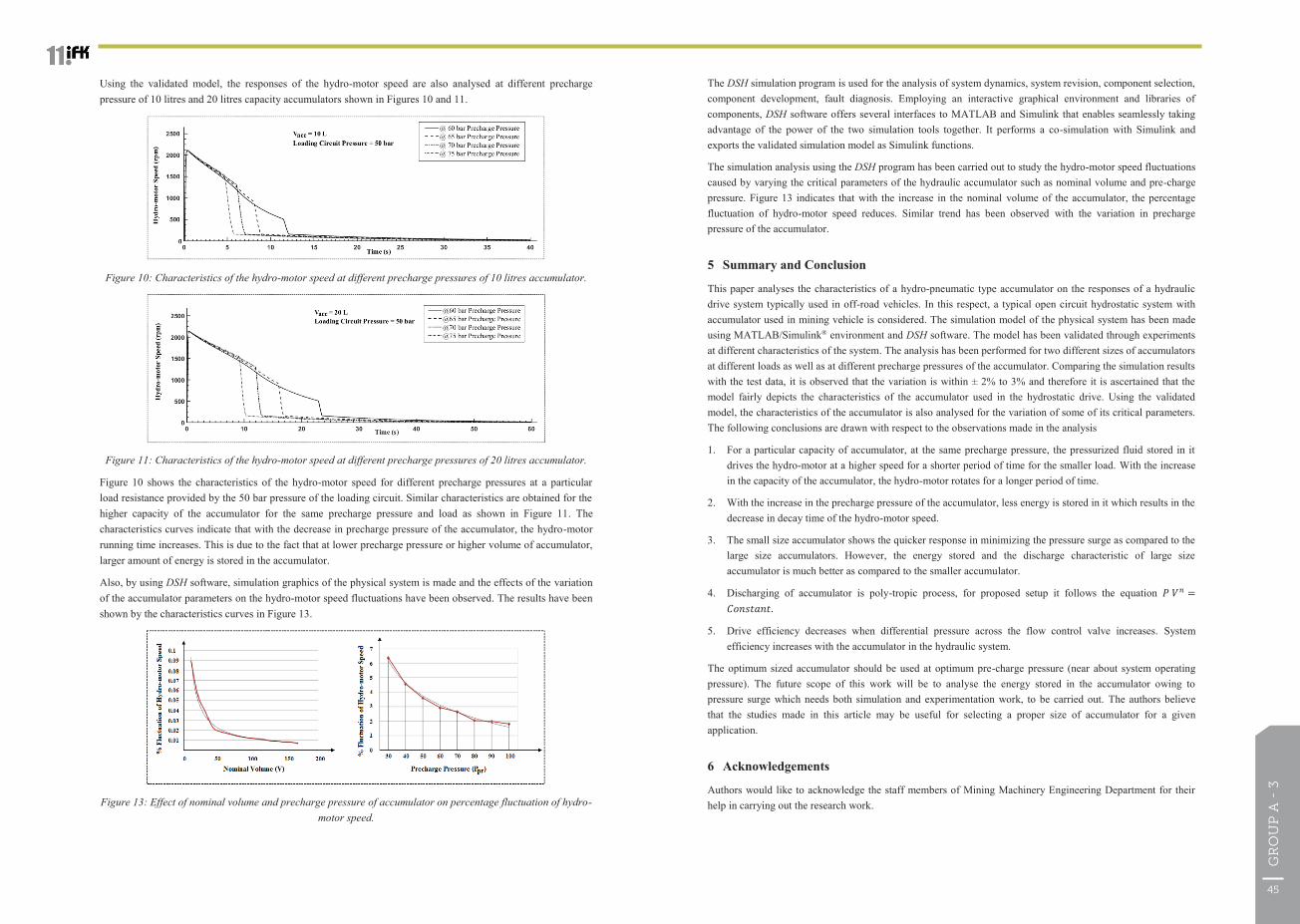
The DSH simulation program is used for the analysis of system dynamics, system revision, component selection, component development, fault diagnosis. Employing an interactive graphical environment and libraries of components, DSH software offers several interfaces to MATLAB and Simulink that enables seamlessly taking advantage of the power of the two simulation tools together. It performs a co-simulation with Simulink and exports the validated simulation model as Simulink functions.
The simulation analysis using the DSH program has been carried out to study the hydro-motor speed fluctuations caused by varying the critical parameters of the hydraulic accumulator such as nominal volume and pre-charge pressure. Figure 13 indicates that with the increase in the nominal volume of the accumulator, the percentage fluctuation of hydro-motor speed reduces. Similar trend has been observed with the variation in precharge pressure of the accumulator.
5 Summary and Conclusion
This paper analyses the characteristics of a hydro-pneumatic type accumulator on the responses of a hydraulic drive system typically used in off-road vehicles. In this respect, a typical open circuit hydrostatic system with accumulator used in mining vehicle is considered. The simulation model of the physical system has been made using MATLAB/Simulink® environment and DSH software. The model has been validated through experiments at different characteristics of the system. The analysis has been performed for two different sizes of accumulators at different loads as well as at different precharge pressures of the accumulator. Comparing the simulation results with the test data, it is observed that the variation is within ± 2% to 3% and therefore it is ascertained that the model fairly depicts the characteristics of the accumulator used in the hydrostatic drive. Using the validated model, the characteristics of the accumulator is also analysed for the variation of some of its critical parameters. The following conclusions are drawn with respect to the observations made in the analysis
1. For a particular capacity of accumulator, at the same precharge pressure, the pressurized fluid stored in it drives the hydro-motor at a higher speed for a shorter period of time for the smaller load. With the increase in the capacity of the accumulator, the hydro-motor rotates for a longer period of time.
2. With the increase in the precharge pressure of the accumulator, less energy is stored in it which results in the decrease in decay time of the hydro-motor speed.
3. The small size accumulator shows the quicker response in minimizing the pressure surge as compared to the large size accumulators. However, the energy stored and the discharge characteristic of large size accumulator is much better as compared to the smaller accumulator.
4. Discharging of accumulator is poly-tropic process, for proposed setup it follows the equation 𝑃𝑃 𝑉𝑉𝑛𝑛 =𝐶𝐶𝐶𝐶𝐶𝐶𝐶𝐶𝐶𝐶𝐶𝐶𝐶𝐶𝐶𝐶.
5. Drive efficiency decreases when differential pressure across the flow control valve increases. System efficiency increases with the accumulator in the hydraulic system.
The optimum sized accumulator should be used at optimum pre-charge pressure (near about system operating pressure). The future scope of this work will be to analyse the energy stored in the accumulator owing to pressure surge which needs both simulation and experimentation work, to be carried out. The authors believe that the studies made in this article may be useful for selecting a proper size of accumulator for a given application.
6 Acknowledgements
Authors would like to acknowledge the staff members of Mining Machinery Engineering Department for their help in carrying out the research work.
The 11th International Fluid Power Conference, 11. IFK, March 19-21, 2018, Aachen, Germany
Using the validated model, the responses of the hydro-motor speed are also analysed at different precharge pressure of 10 litres and 20 litres capacity accumulators shown in Figures 10 and 11.
Figure 10: Characteristics of the hydro-motor speed at different precharge pressures of 10 litres accumulator.
Figure 11: Characteristics of the hydro-motor speed at different precharge pressures of 20 litres accumulator.
Figure 10 shows the characteristics of the hydro-motor speed for different precharge pressures at a particular load resistance provided by the 50 bar pressure of the loading circuit. Similar characteristics are obtained for the higher capacity of the accumulator for the same precharge pressure and load as shown in Figure 11. The characteristics curves indicate that with the decrease in precharge pressure of the accumulator, the hydro-motor running time increases. This is due to the fact that at lower precharge pressure or higher volume of accumulator, larger amount of energy is stored in the accumulator.
Also, by using DSH software, simulation graphics of the physical system is made and the effects of the variation of the accumulator parameters on the hydro-motor speed fluctuations have been observed. The results have been shown by the characteristics curves in Figure 13.
Figure 13: Effect of nominal volume and precharge pressure of accumulator on percentage fluctuation of hydro-motor speed.
45
GR
OU
P A
- 3
The 11th International Fluid Power Conference, 11. IFK, March 19-21, 2018, Aachen, Germany
𝜃𝜃M Angular displacement of the hydro-motor [rad]
𝜌𝜌 Mass density of the fluid [kg/m2]
𝜈𝜈 Kinematic viscosity of the fluid [m2/s]
𝜔𝜔M Angular speed of the hydro-motor [rad/s]
𝜔𝜔P Angular speed of the pump [rad/s]
References
/1/ Andersen, T. O., Hansen, M. R., Pedersen, H. C., Regeneration of potential energy in hydraulic forklift trucks, In: The 6th International Conference on Fluid Power Transmission and Control, Hangzhou, pp. 380-384, 2005.
/2/ He, W., Zhang, S., Ge, S. S., Adaptive control of a flexible crane system with the boundary output constraint, In: IEEE Transactions on Industrial Electronics, Vol. 61, No. 8, pp. 4126-4133, 2014.
/3/ Bing, X., Jian, Y., Yang, H. Y., Comparison of energy-saving on the speed control of the VVVF hydraulic elevator with and without the pressure accumulator, In: Mechatronics, Vol. 15, No. 10, pp. 1159-1174, 2005
/4/ Ho, T. H., Ahn, K., K., Modelling and simulation of hydrostatic transmission system with energy regeneration using hydraulic accumulator, In: Journal of Mechanical Science and Technology, Vol. 24, No. 5, pp. 1163-1175, 2010.
/5/ Quan L., Kong X., Li B., et al., Mathematical model, simulation and testing study on damping characteristic controlled by proportional valve, In: Proceedings of the 7th International Conference on Fluid Power Transmission and Control, Hangzhou, China, 7-10 April 2009, pp. 100-105, 2009.
/6/ Chrostowski, H., Kędzia K., The analysis of pneumo - hydraulic accumulator efficiency, applied as element of hybrid driving system, Scientific papers of the University of Pardubice, Series B, The Jan Perner Transport faculty 10 (2004), 2004.
/7/ Rydberg, K., E., Hydraulic hybrids - the new generation of energy efficient drives, In: Proceedings of the 7th International Conference on Fluid Power Transmission and Control, Hangzhou, China, 7-10 April 2009, pp. 899-905, 2009.
/8/ Okoye, C., Jiang, J., Hu, Z., Application of hydraulic power unit and accumulator charging circuit for electricity generation, storage and distribution, In: Proceedings of the 6th International Conference on Fluid Power Transmission and Control, Hangzhou, China, 5-8 April 2005, pp. 224-227, 2005.
/9/ Prodan, D., Gheorghiu, H., Bucuresteanu, A., Mathematical modeling of hydraulic systems with pneumo-hydraulic accumulators, In: Proceedings of the 18th International DAAAM Symposium “Intelligent Manufacturing & Automation: Focus on Creativity, Responsibility and Ethics of Engineers”, Zadar, Croatia, 24–27 October 2007, pp. 613–614, 2007.
/10/ Puddu, P., Paderi, M., Hydro-pneumatic accumulators for vehicles kinetic energy storage: Influence of gas compressibility and thermal losses on storage capability, In: Energy Journal, Vol. 57, pp. 326-335, 2013.
/11/ Kumar, A., Dasgupta, K., Das, J., Analysis of decay characteristics of an accumulator in an open-circuit hydrostatic system with pump loading. In: Proc IMechE Part I: J Systems and Control Engineering, U.K. Sage, Vol. 231, No. 4, pp. 312-326, 2017.
/12/ Kumar, A., Das, J., Dasgupta, K., Barnwal, M., K., Effect of Hydraulic Accumulator on Pressure Surge of a Hydrostatic Transmission System, In: J. Inst. Eng. India Ser. C, Springer 2017, DOI 10.1007/s40032-017-0351-4.
The 11th International Fluid Power Conference, 11. IFK, March 19-21, 2018, Aachen, Germany
Nomenclature
Variable Description Unit
𝐴𝐴(Δ𝑃𝑃CV) Instantaneous orifice passage area control valves [m2]
𝐵𝐵M Viscous damping coefficient of load and hydro-motor [-]
𝐶𝐶D Flow discharge coefficient [-]
𝐶𝐶DLam Flow discharge coefficient corresponding to laminar flow [-]
𝐶𝐶lm Leakage coefficient of the hydro-motor [-]
𝐷𝐷M Volume displacement rate of the hydro-motor [cm3/rev]
𝐷𝐷Orifice Orifice diameter of control valves [m]
𝐷𝐷P Volume displacement rate of the pump [cm3/rev]
𝐷𝐷PL Volume displacement rate of the loading pump [cm3/rev]
𝐽𝐽M Total inertia of hydro-motor shaft [kg-m2]
𝑘𝑘HP Hagen-Poiseuille coefficient [-]
𝑘𝑘leak Leakage coefficient [-]
𝑃𝑃a Fluid pressure in the accumulator [bar]
Δ𝑃𝑃CV Pressure difference across the ports of the control valves [bar]
Δ𝑃𝑃L Load-induced pressure drop across the hydro-motor [bar]
Δ𝑃𝑃P Pressure difference across the ports of the hydraulic pump [bar]
Δ𝑃𝑃PL Pressure difference across the ports of the loading pump [bar]
𝑞𝑞acc Flow through the accumulator [m3/sec]
𝑞𝑞CV Flow rate through pressure relief valve [m3/sec]
𝑞𝑞M Actual outlet flow rate of the hydro-motor [m3/sec]
𝑞𝑞P Actual outlet flow rate of the pump [m3/sec]
𝑅𝑅𝑅𝑅 Reynolds number [-]
𝑅𝑅𝑅𝑅cr Critical Reynolds number [-]
𝑇𝑇L Load torque provided by the loading unit [N-m]
𝑇𝑇th Theoretical torque input to the hydro-motor [N-m]
𝑉𝑉a Volume of nitrogen gas in the accumulator bladder [m3]
𝑉𝑉F Volume of the hydraulic fluid in the accumulator [m3]
𝑉𝑉M Volume of the fluid at the hydro-motor plenum [m3]
⍺M Angular acceleration of the hydro-motor [rad/s2]
𝛽𝛽 Apparent bulk modulus of the fluid [bar]
𝛾𝛾 Specific heat ratio of gas used in the accumulator bladder [-]
47
GR
OU
P A
- 3
The 11th International Fluid Power Conference, 11. IFK, March 19-21, 2018, Aachen, Germany
of the accumulator, pump is in unloaded condition. Hence, two boundary conditions exists at initial and final state of discharging of the accumulator.
2416.6 rpm = 40.3 rev/s = 1
900 rpm= 15 rev/s = 2
Therefore, Total revolution = 3362 cc/ (DM) = 3362 cc /12 cc/rev = 280.2 rev
So, from equation (10)
1
- 1211
dsttt
= 280.2 rev
1
15 - 3.40 11
dsttt
= 280.2 rev (11)
Also;
dsttt 1211 (12)
dsttt 15 3.40 11 (13)
Substituting the value of 1t from equation (13) in equation (11) and taking the value of n as 1.4 considering the
discharging of accumulator as an adiabatic process, the value of dst is calculated as
dst = 11.49 s ≈ 11.50 s
From the experimental investigation, it has been found that the time required during the discharge of 20 litres capacity accumulator; when pump is in unloaded condition is 11.4 s and during charging; when pump is in
loaded condition is 55.8 s. Substituting the value of dst in equation (13), the actual path of discharging of
accumulator is obtained as;
γ = 1.72
The 11th International Fluid Power Conference, 11. IFK, March 19-21, 2018, Aachen, Germany
/13/ Hydac Electronic GMBH, Operating Manual: Part No. 669855, Portable Data Recorder HMG 3010, Edition 2012-06-28-V04 R01.
/14/ Yamada, H., Shiozaki, S., Matsuyama, H., et al., Energy Saving System for Hydraulic Excavator (Simulation of Power Assistant System with Accumulator). In: Proeedings of the 6th JFPS International Symposium on Fluid Power, Tsukuba, 7-10 November 2005, pp. 646-651, 2005.
/15/ N. Kumar et al., Dynamic analysis of a closed-circuit hydrostatic summation drive using bent axis motors, In: Proc IMechE Part I: J Systems and Control Engineering, U.K. Sage, Vol 229, Issue 8, pp. 761-777, 2015.
/16/ The Mathworks. SimHydraulicsR 1. Reference; The Mathworks Inc.: Natick, MA, USA, 2012.
Appendix I
Estimation of polytropic exponent for the accumulator modulation.
Variation of accumulator pressure with volume is shown in Figure 13 (a). The displacement (𝐷𝐷M) of the hydro-motor is constant; therefore it may be assumed that the rotation (rpm) of the hydro-motor is similar to the discharge characteristic of the accumulator as shown be in Figure 13 (b).
Figure 13: (a) Discharge characteristics of accumulator (b) Rotational characteristics of a hydraulic motor
Where
t1 = starting time of the discharging of the accumulator (s).
t2 = t1+tds = Finishing time of the discharging of the accumulator.
tds = Time taken in discharging of the accumulator.
ω1 = Starting speed of the hydro-motor (rps).
ω2 = Final speed of the motor when accumulator is completely discharged.
Now, Ø = Total revolution of the hyro-motor = Shaded area under the curve shown in Figure 13 (b).
The shaded area can be calculated as:
1
- 1211
dsttt
(10)
Where Equation (10) is the work done in adiabatic process
From the experimental analysis, it is observed that when system pressure is 100 bar, maximum oil flowing through the motor is 29 lpm at 2416.6 rpm and minimum flow of oil is 10.8 lpm at 900 rpm. During discharging


![INVESTING IN A BETTER TOMORROW - coima.com4].pdf · • Simona Pozzoli • Federica Pratellesi • Marco Puddu ... 48 53 La sostenibilità nella filiera immobiliare I criteri ESG](https://static.documents.pub/doc/80x56/5c67217c09d3f22d638b5ab8/investing-in-a-better-tomorrow-coima-4pdf-simona-pozzoli-federica.jpg)


